

Page 1

GETTING STARTED GUIDE
Cisco Aironet 3500 Series Lightweight Access Point
1 About this Guide
2 Safety Instructions
3 Unpacking
4 Overview
5 Configuring the Access Point
6 Mounting the Access Point
7 Securing the Access Point
8 Deploying the Access Point on the Wireless Network
9 Troubleshooting
10 Declarations of Conformity and Regulatory Information
11 Configuring DHCP Option 43 and DHCP Option 60
12 Access Point Specifications
Page 2

1 About this Guide
This Guide prov ide s instru cti ons o n how to insta ll an d conf igu re you r Cisc o Airo net 35 00 S eries
Access Point. This guide also provides mounting instructions and limited troubleshooting procedures.
2 Safety Instructions
Translated versions of the following safety warnings are provided in the translated safety warnings
document that is shipped with yo ur ac cess point. The tra nslated warni ngs ar e al so i n the Translated
Safety Warnings for Cisco Aironet Access Points, which is available on your documentation C D and
cisco.com.
Warning
Warning
Warning
Warning
IMPORTANT SAFETY INSTRUCTIONS
This warning symbol means danger . You are in a situation that could cause bodily injury.
Before you work on any equipment, be aware of the hazards involved with electrical
circuitry and be familiar with standard practices for preventing accidents. Use the
statement number provided at the end of each warning to locate its translation in the
translated safety warnings that accompanied this device.
SAVE THESE INSTRUCTIONS
Read the installation instructions before you connect the system to its power source.
Statement 1004
This product must be connected to a Power-over-Ethernet (PoE) IEEE 802.3af compliant
power source or an IEC60950 compliant limited power source.
Installation of the equipment must comply with local and national electrical codes.
Statement 1074
Statement 1071
Statement 353
2
Page 3

Warning
Warning
Warning
Caution Do not use the supplied plastic wall anchors to mount the access point on a ceiling
Caution This product and all int erconnec ted equi pment must be ins talled in doors with in the same
This product relies on the building’s installation for short-circuit (overcurrent)
protection. Ensure that the protective device is rated not greater than:
20A.
Statement 1005
Do not operate your wireless network device near unshielded blasting caps or in an
explosive environment unless the device has been modified to be especially qualified for
such use.
In order to comply with FCC radio frequency (RF) exposure limits, antennas should be
located at a minimum of 7.9 inches (20 cm) or more from the body of all persons.
Statement 332
because they will not support the weight of the access point. The fasteners used must be
capable of maintaining a minimum pullout force of 20 lbs (9 kg) and must use all 4
indented holes on the low-profile mounting bracket.
building, including the associated LAN connections as defined by Environment A of the
IEEE 802.af Standard.
Statement 245B
Note The access point is su itable for use in enviro nmen tal air sp ace in a ccorda nce with sectio n
300.22.C of the National Electrical Code and sections 2-128, 12-010(3), and 12-100 of the
Canadian E lec tr ic al C o de, P a rt 1, C 22 . 1. You should not i ns ta ll th e p owe r su p pl y o r po w e r
injector in air handling spaces.
Note Use only with listed ITE equipment.
3
Page 4

3 Unpacking
Follow these steps:
Step 1 Unpack and remove the access point and the accessory kit from the shipping box.
Step 2 Return any packing material to the shipping container and save it for future use.
Step 3 Ve ri fy that you ha ve r ecei ved t he i tem s sho w n in Figure 1. If any item is missing or damaged,
contact your Cisco representative or reseller for instructions.
4
Page 5
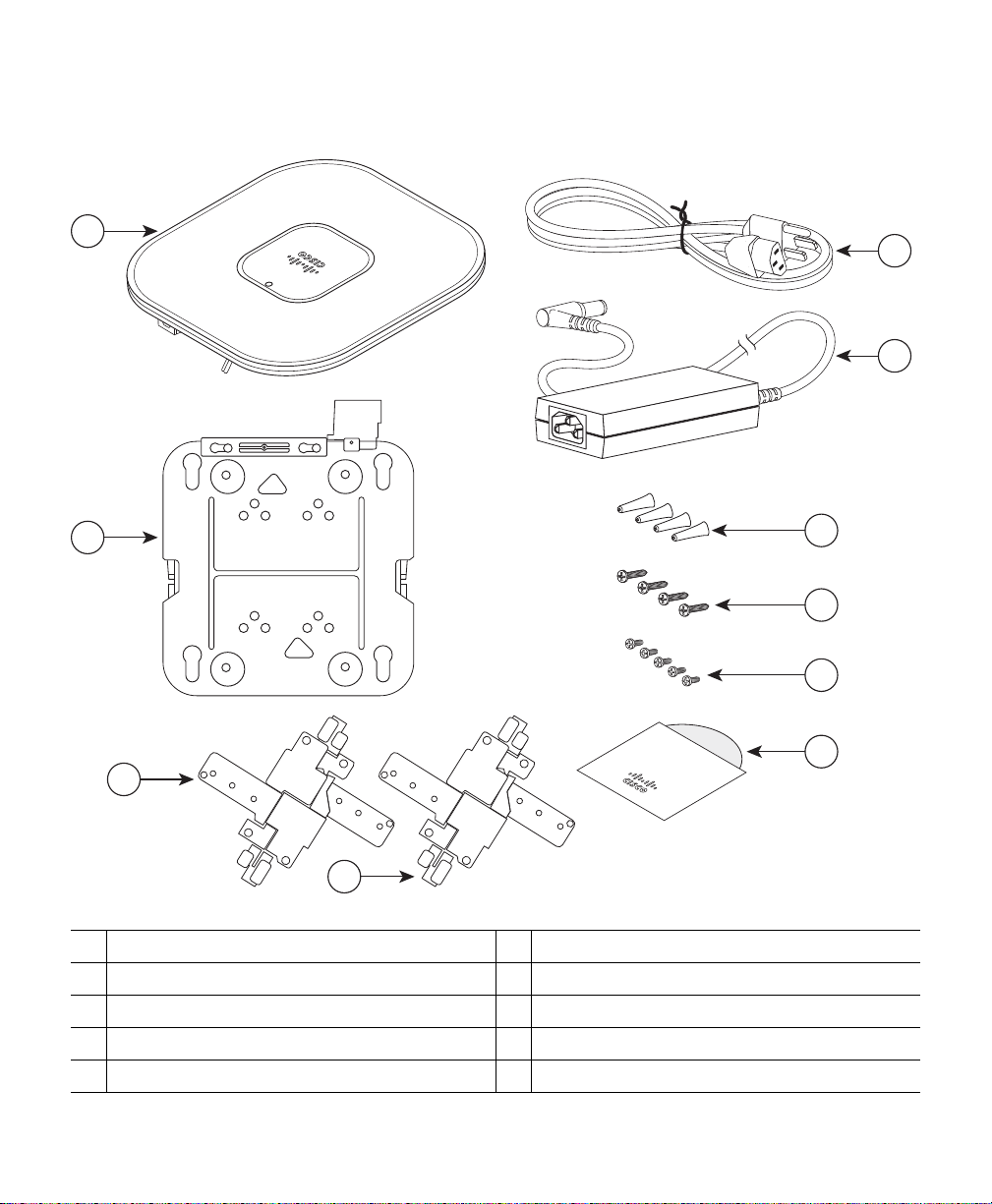
Figure 1 Shipping Box Contents
272374
Documentation
CD-ROM
3
4
2
1
7
8
5
6
9
10
Standard ceiling adjustable T-rail clip
1
Recessed ceiling adjustable T-rail clip
2
Low-profile mount ing bra cke t
3
3500 series access point
4
AC power cord
5
DC power supply
6
#8 plastic wall anchors
7
#8 X 1-in. (2.54 cm) Phillips head fasteners
8
6-32 x 1/4 in. (0.6 3 cm) flat he ad screw s
9
10
Documentation CD-ROM
5
Page 6
272377
2 3 4
1 5
6 6
4 Overview
The following illustrations show the access point connections and features.
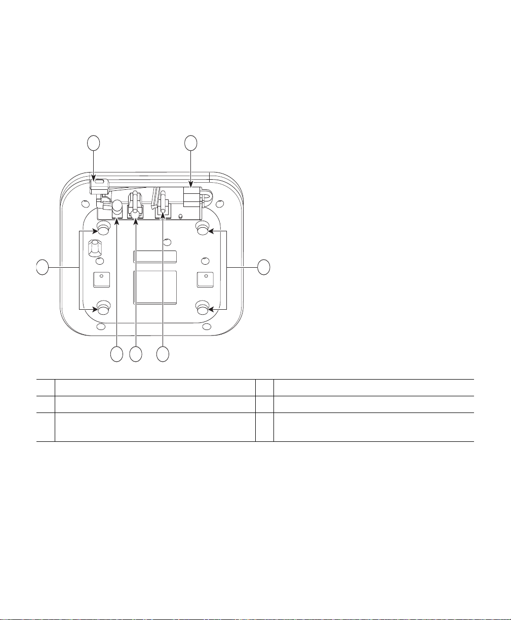
Figure 2 Access Point Ports and Connections
Kensington lock slot
1
Power co nn ec ti on
2
Ethernet port
3
6
Console por t
4
Security padlock and hasp
5
Low-profile mounting bracket pins (feet for
6
desk or table-top mount)
Page 7

5 Configuring the Access Point
This section describes how to connect the access point to a wireless LAN controller. Because the
configuration process takes place on the controller, see the Cisco Wireless LAN Controller
Configuration Guide for additional information. This guide is available on cisco.com.
The Controller Discovery Process
The 3500 series acc ess po int use s the I ETF stan dard Contro l and Pr ovisi oning of Wireless Acce ss
Points Protocol (CA PWAP) to communicate between the contr oller and oth er wireless a ccess points o n
the network. CA PWAP is a standard, intero perab le pr otoco l whic h enab les an acce ss con troll er to
manage a collection of wireless termination points. The discovery process using CAPWAP is identical
to the Lightweight Access Point Protocol (LWAPP) used with previous Cisco Aironet access points.
LWAPP- ena b led acce ss po in ts a re compa ti bl e with CA PWAP and conversion to a CAPWAP controller
is seamless. De ploy ment s can c ombi ne CAPWAP and LWAPP software on the contro lle rs.
The functionality provided by the controller does not change except for customers who have Layer 2
deployments , whic h CAP WAP does not support.
In a CAPW AP environment, a wireless access point discovers a controller by using CAPWAP discovery
mechanisms and then sends it a CAPWAP join request. The controller sends the access point a
CAPWAP join response allo win g the ac c e ss po i nt t o jo in th e c on tro ll e r. When the acces s po in t j o in s
the controller, the controller manages its configuration, firmware, control transactions, and data
transactions.
Note For additional infor mati on a bout the dis cov ery proce ss and CAP WAP, see the Cisco Wireless
LAN Controller Software Configuration Guide. This document is available on cisco.com.
Note CAPWAP support is provided in controller software release 5.2 or later. Your controller must
be running rele ase 5. 2 or later.
Note You cannot edit or query any access point using the controller CLI if the name of the access
point conta i n s a sp ac e .
Note Make sure that the controller is set to the current time. If the controller is set to a time that
has already occurr ed, the acces s point mig ht not join the c ontro ller becau se its cer tificate may
not be valid for that time.
7
Page 8

Access points mus t be discover ed by a control ler before they can become an a ctive part o f the network.
The 3500 series access point supports these controller discovery processes:
• Layer 3 CAPWAP discovery—Can occur on different subnets than the access point and uses IP
addresses and UDP packets rather than MAC addresses used by Layer 2 discovery.
• Over-the-air provisioning (OTAP)—This f eatu r e is su pp or t ed by Ci sc o 44 00 ser ies cont r ol le rs . I f
this feature is enabled on the controller, all joined access points transmit wireless CAPWAP
neighbor messages, and new access points receive the controller IP address from these messages.
This feature is dis abl ed by de fault and sho uld r emain disa bled when all acces s poin ts ar e inst alled.
Additional information about OTAP is available on cisco.com at the following link:
http://www.ciscosystems.com/en/US/p roducts/ps 6366/p roducts_te ch_note0918 6a008093d 74a.shtml
• Locally stored controller IP address discovery—If the access point was previously joined to a
controller, the IP addresses of the primary, secondary, and tertiary controllers are stored in the
access point’s non-volatile memory. This process of storing controller IP addresses on an access
point for later deployment is called priming the access point. For more information about priming,
see the
• DHCP server disc ov er y —Thi s fea tur e uses DHCP op tio n 43 to pro vide contr ol le r IP addr ess es to
the access points. Cisco switches support a DHCP server option that is typically used for this
capability. For more information a bou t DH CP op tio n 4 3, see the
and DHCP Option 60” section on page 43.
• DNS discovery—The access point can discover controllers through your domain name server
(DNS). For the access point to do so, you must configure your DNS to return controller IP
addresses in response to CISCO-LWAPP-CONTROLLER.localdomain, where localdomain is the
access point domain name. Co nfig uring the C ISCO-LWAPP-CONTROLLER provides backwards
compatibility in an existing customer deployment. When an access point receives an IP address
and DNS information from a DHCP server, it contacts the DNS to resolve
CISCO-LWAPP-CONTROLLER.localdomain. When the DNS sends a list of contr oller IP
addresses, the access point sends discovery requests to the controllers.
“Performing a Pre- In stalla tion Conf igu rati on” sec tion on page 9.
“Configuring DHCP Option 43
Preparing the Access Point
Before you mount an d dep loy your ac cess p oint, we reco mmen d tha t you p erf orm a site s urvey (or use
the site planning tool) to determine the best location to install your access point.
You should have the following information about your wireless network available:
• Access point locations.
• Access poin t m ou n tin g o pti on s: be lo w a s us pe nd e d ce ili ng, on a fl at h or iz o nta l s ur fa ce , or on a
desktop.
8
Page 9

Note You can mount the access point above a suspended ceiling but you must purchase
additional mounting hardware: See
additional information.
• Access point pow er opt ion s: powe r supp lie d by a DC po wer sup ply, PoE from a network devic e,
or a PoE power injector/hub (usually located in a wiring closet).
Note Access points mounted in a building’s environmental airspace must be powered using PoE
to comply with safety regulations.
Cisco recommends that you make a site map showing access point locations so that you can record the
device MAC addresses from each location and return them to the person who is planning or managing
your wireless network.
“Mounting the Access Point” section on page 13 for
Installation Summary
Installing the access point involves these operations:
• Performing a pre-installation configuration (optional)
• Mounting the access point
• Grounding the access point
• Deploying the access point on the wireless network
Performing a Pre-Installation Configuration
The following procedures ensure that your access point installation and initial operation go as
expected. A pre-installation configuration is also known as priming the access point. This procedure
is optional .
Note Performing a pre-installation configuration is an optional procedure. If your network
controller is properly configured, you can install your access point in its final location and
connect it to the network from there. See the
Network” section on page 24 for details.
“Deploying the Access Point on the Wireless
9
Page 10
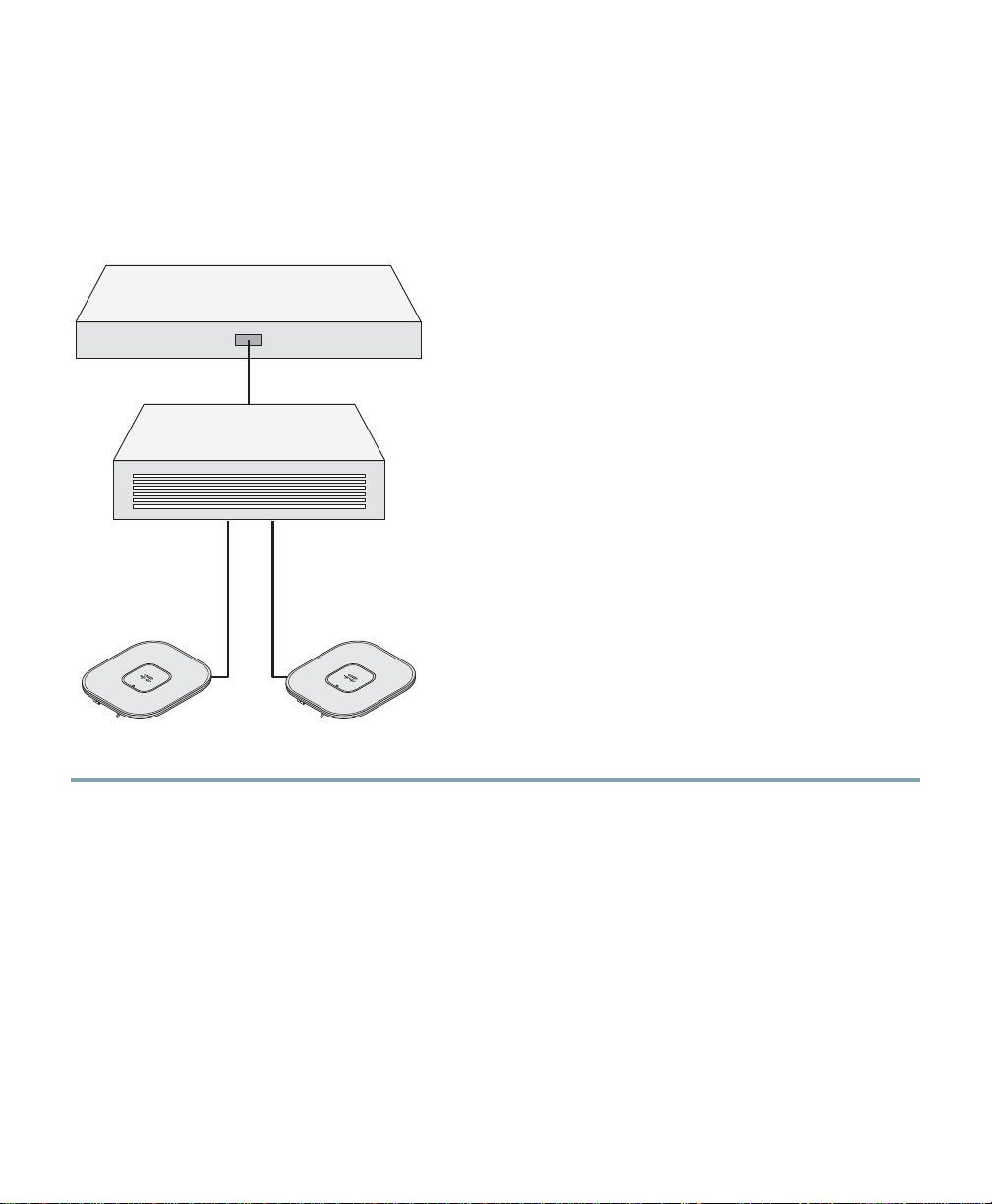
Controller
Layer 3
devices
Cisco Aironet
access points
272488
Pre-Installation Configuration Setup
Figure 3 shows the pre-installation configuration setup.
Figure 3 Pre-Installation Config ur a ti on Set up
Follow these steps t o perfo rm th e pre- ins talla tion conf igur atio n.
Step 1 Make sure that the Cisco wireless LAN controller DS port is connected to the network. Use
the CLI, web-browser interface, or Cisco WCS procedures as described in the appropriate
Cisco wireles s LA N c ont ro lle r guide.
a. Make sure that access points have Layer 3 connectivity to the Cisco wireless LAN controller
Management and AP-Manager Interface.
b. Configure the switch to which your access point is to attach. See the Cisco Unified Wireless
Network WLAN Controller Guide: Cisco 440x Series WLAN Controllers for additional
information.
c. Set the Cisco wireless LAN controller as the master so that new access points always join with
it.
d. Make sure DHCP is enabled on the network. The access point must receive its IP address
through DHCP.
10
Page 11

e. CAPWAP UDP ports must not be blocked in the network.
f. The access point must be able to find the IP address of the controller. This can be
accomplished using DHCP, DNS, or IP subnet broadcast. This guide describes the DHCP
method to convey the controller IP address. For other methods, refer to the product
documentation. See also the
information.
Step 2 Apply power to the access point:
a. The access point is 802.3af (15.4 W) compliant and can be powered by any of the following
802.3af compliant devices:
–
2106 control ler
–
WS-C3550, WS-C3560, and WS-C3750 switches
–
C1880 switch
–
2600, 2610, 2611, 2621, 2650, and 2651 multiservice platforms
–
2610XM, 2611X M, 26 21 XM, 265 0X M , 2 65 1XM, and 2691 mu lti serv ic e p la tfo rms
–
2811, 2821, and 2851 integrated services routers
–
3620, 3631-telco, 3640, and 3660 multiservice platforms
–
3725 and 3745 multiservice access routers
–
3825 and 3845 integrated services routers
The access point can also be powered by any of the following optional external power
sources:
–
Any 802.3af com plia nt po wer in jec tor
“Using DHCP Option 43” section on page 26 for more
Note The 3500 series acc es s po in t req ui re s a Gigi b it E the rn et link to pre v e nt th e Et he rn et
port from becoming a bottleneck for traffic because wireless traffic speeds exceed
transmit speeds of a 10/100 Ethernet port.
–
1250 series access point power injector (AIR-PWRINJ4)
–
1100/1200 series access point DC power supply (AIR-PWR-SPLY)
b. As the access point attempts to connect to the controller , the LEDs cycle through a green, red,
and amber sequence, which can take up to 5 minutes.
Note If the access point remains in this mode for more than five minutes, the access point is
unable to find the Master Cisco wireless LAN controller. Check the connection between
the access point and t he Cisc o wirele ss LAN co ntr oller an d be su re that th ey are on t he
same subnet.
11
Page 12

c. If the access point shuts down, check the power source.
d. After the access point finds the Cisco wireless LAN controller, it attempts to download the
new operating system code if the access point code version differs from the Cisco wireless
LAN controller code version. While this is happening, the Status LED blinks dark blue.
e. If the operating system download is successful, the access point reboots.
Step 3 Configure the access point if required. Use the controller CLI, controller GUI, or Cisco WCS
to customize the access-point-specific 802.11n network settings.
Step 4 If the pre-installation configuration is successful, the Status LED is green indicating normal
operation. Disconnect the access point and mount it at the location at which you intend to
deploy it on the wireless network.
Step 5 If your access point does not indicate normal operation, turn it off and repeat the
pre-install a ti on c o nf i gur a tio n.
Note When you are installing a Layer 3 access point on a different subnet than the Cisco
wireless LAN controller, be sure that a DHCP server is reachable from the subnet on
which you will be installing the access point, and that the subnet has a route back to
the Cisco wireless LAN con troll er. Al so be sur e that the route back to t he Cisc o
wireless LAN contr oller has destina tion UDP ports 5246 and 5247 open for CAPWAP
communications. Ensure that the route back to the primary, secondary, and tertiary
wireless LAN co ntr oller a llo ws IP pa cke t frag ment s. Fi nall y, be sure that if address
translation is used, that the access point and the Cisco wireless LAN controller have
a static 1-to-1 NAT to an outside address. (Port Address Translation is not
supported.)
12
Page 13

6 Mounting the Access Point
This section des crib es ho w to mou nt the acces s poi nt usin g its su ppl ied mo unti ng har dwa re. Use the
provided low-profi le mounting br acket (See
surface or below a standard or recessed suspended ceiling. The low-profile mounting bracket is not
necessary when mounting the access point on a table or desk top.
Note The integrated antenna design of the 3500 series access point is designed for horizontal
surfaces, (table top and ceiling installations). When mounted to such surfaces, the integrated
antennas produce the best antenna radiation pattern. For advanced features such as voice,
location, and rogue access point detection, ceiling mounting is strongly recommended.
However, for smaller areas such as conference rooms, kiosks, transportation, and hot-spot
usage where the customer is concerned primarily with data coverage and not advanced
features, this uni t may be w all mounte d using the supplie d plastic w all anch ors and #8 screw s.
Caution Do not use the plastic wall anchors to mount the access point on a ceiling because they
will not support the weight of the access point. The fasteners used must be capable of
maintaining a minimum pullout force of 20 lbs (9 kg) and must use all 4 indented holes
on the low-profile mounting bracket.
Figure 4) to mount the access point on any flat horizontal
13
Page 14
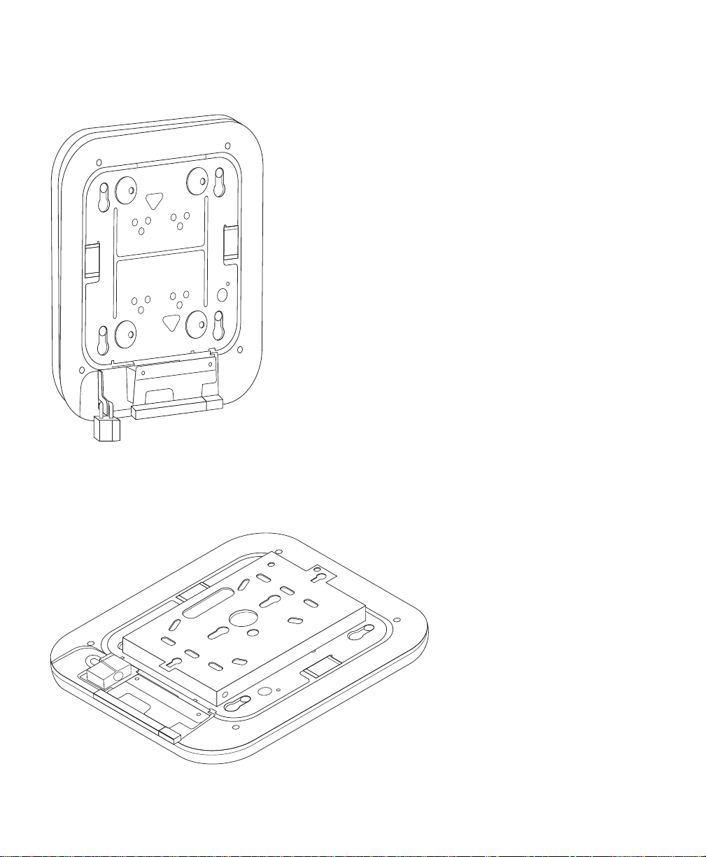
Figure 4 Low Profile Mounting Bracket Installed on the 3500 Series Access Point
272380
Y o u can a lso mo unt the acce ss p oint abo ve a sus pend ed ceil ing or to a ju nction box u sing th e option al
adapter bracket.
Figure 5 shows the optional adapter bra cket installe d on the 3500 seri es access point.
Figure 5 Optional Adapter Bracket Installed on the 3500 Series Access Point
272384
14
Page 15

Note The optional adapter brac ket can also be used to mount the access poi nt on suspended ceil ing
installations using existing mounting hardware for the 1100, 1130, 1200, or 1240 series
access points.
See the Cisco Aironet 3500 Series Access Point Alternate and Upgrade Mounting Instructions for
procedures for mounti ng an 3500 s eries acce ss point on 110 0, 1130, 1200, or 1240 series acce ss point
ceiling mounting hardware. This document ships with the optional adapter plate and is availa ble on
cisco.com.
Mounting Hardware
The access point ships with the following mounting hardware (See Figure 1):
• One low-profile mounting bracket
• One standard ceiling adjustable T-rail clip
• One recessed ceiling adjustable T-rail clip
• Four #8 Phillips head fasteners
• Four #8 wall anchors
• Four 6-32 x 1/4 in. flat head sc rews
The following mounting hardware is available as an orderable option:
• Adapter plate for the following mounting scenarios:
–
Above a suspended ceiling
–
To a junction box
–
To existing 1100, 1130, 1200, or 1240 series mounting hardware
Mounting the Access Point on a Horizontal Surface
Use the provided low-profile mounting bracket to mount the access point to flat, horizontal surfaces
such as a ceiling. If you are mounting the access point to a junction box, you should use the optional
adapter plate.
15
Page 16

Note The access point’s integrated antennas perform best when the access point is mounted on
horizontal surfaces such as a table top or ceiling. For advanced features such as voice,
location, and rogue access point detection, ceiling mounting is strongly recommended.
However, for smaller areas such as confe rence rooms, kiosks , transportation en vironments, or
hot-spot usage where data coverage is the primary concern, the unit may be wall mounted
using the supplied plastic wall anchors and #8 screws.
The following procedure describes the steps required to mount the access point on a ceiling constructed
of 3/4-in (19.05-mm) or thicker plywood using the #8 fasteners provided. Procedures for other
materials may differ and you may need to p rovide add itional appr opriate fasten ers.
Follow these steps to mount the access point on a plywood ceiling.
Step 1 Use the low-profile mounting brack et as a template to m ark the locatio ns of the four indente d
mounting holes. See callout 3 in
Caution Be sure to mark all four locations. To ensure a safe and secure installation, make sure you
are using adequate fasteners and mount the acces s point using no le ss than four fasten ers.
Figure 6.
Step 2 Remove four #8 Phillips head screws from the mounting kit plastic bag. Discard the four
plastic anchors.
16
Page 17

Figure 6 Low-Profile Mounting Bracket Details
272376
2 3 3 2
2 3 3 24
1
Grounding post
1
Access point mounting keyholes
2
Indented mounting holes
3
Cable access cover
4
Step 3 Use a #29 drill (0.136 0-in. [3.4772 mm]) bit to drill a pilot hole at th e mounting hole locatio ns
you marked.
Note The pilot hole size varies accor ding to the mate rial and t hickn ess yo u are fast ening.
Cisco recommends that you test the material to determine the ideal hole size for your
mounting application.
Step 4 (Optional) Drill or cut a cable access hole near and below the location of the low-profile
mounting plate cable access cover large enough for the Ethernet cable, building ground wire,
and power cables.
Step 5 If you performed Step 4, pull the cables through the access hole until you have about 1 ft
(30.4 cm) of cable protruding from the hole.
Step 6 Attach the building gr ou nd wi re to th e l ow- pro f ile mo un ting br acke t g round in g po st. See th e
“Grounding t he Acc ess Po int ” sec tion on page 21 for general grounding instructions.
Step 7 Position the low- prof ile mo unt ing pl ate mo unt ing ho les (wit h inden ts do wn) ov er the pil ot
holes.
17
Page 18

272375
5
4
1
2
3
Step 8 Insert a #8 Phillips head fastener into each mounting hole and tighten.
Step 9 Align the access point feet with the l arge part of the key hole mounting slots on the low-profi le
mounting plate. When positioned correctly, the cable access cover will fit inside the access
point connect or bay.
Step 10 Gently slide the access point onto the low-profile mounting bracket keyhole slots until it clicks
into place.
Step 11 Install the E thern et and powe r cabl es.
Mounting the Access Point Below a Suspended Ceiling
Follow these steps to mount the access point below a standard or recessed suspended ceiling. See
Figure 7.
Figure 7 Suspended Ceiling Mounting Details
Access point mounting keyhole
1
Adjustable T-rail clip
2
Grounding point
3
18
Access point cable access cover
4
5
Ceiling T-rail
Page 19

121758
3
3
1
1
2
2
2
2
CEILING
GRID
WIDTH
38 24 15
ABC
1-1/2 15/16 9/16
MM
INCH
CEILING
GRID
WIDTH
38 24 15
ABC
1-1/2 15/16 9/16
MM
INCH
Follow these steps to mount the access point below a suspended ceiling.
Step 1 Decide wher e you want t o moun t the acces s po int on your suspe nde d cei ling .
Step 2 Select the appropriate adjustable T-rail clip for your suspended ceiling (standard or recessed)
and open the clip completely. See
Figure 8.
Figure 8 Adjustable T-Rail Clip
1 T-rail locking screws 3 T-rail width detents (A, B, or C)
2 Mou nting pla te screw holes
Step 3 Place the T-rail clip over the T-rail and close it to the appropriate detent (A, B, or C).
Step 4 Use a screwdriver to tighten the two T-rail locking screws to prevent the T-rail clip from
sliding along the T-rail.
Step 5 Observe the T-rail width detent letter (A, B, or C) that corresponds to the T-rail width.
Step 6 Align the co rres pond ing ho les (A, B, or C) on the low- prof ile mo unt ing pl ate o ver the T-rail
mounting plat e hol es.
19
Page 20

272429
MODE
CONSOLE ETHERNET
48VDC
Product contains cryptographic features and is subject to
US and local laws governing import, export, transfer, and use.
Step 7 Hold the low-profile mounting bracket and insert a 6-32 x 1/4 in. flat head screw into each
of the four corresponding holes (A, B, or C) and tighten.
Step 8 If needed, drill or cut a cable access hole in the ceiling tile large enough for the Ethernet and
power cables. Pull the cables through the access hole until you have about 1 foot of cable
protruding fr om the hole.
Step 9 (Optional )—Gro und t he acc ess point to a su itab le buil din g grou nd. See th e “Gro undi ng th e
Access Point” section on page 21 for general grounding instructions.
Step 10 Install the Ethernet and power cables. Be sure to route the power cable through the strain
relief as s ho wn in
Figure 9.
Figure 9 Routing the Power Cable
Step 11 Align the access point fe et over the keyhol e mounting slots on the low-pr ofile mounti ng plate.
If you created a hole for the c ables, make s ure th e access poin t is posi tioned so that the cab les
reach their respect ive port s.
Step 12 Gently slide the access point onto the low-profile mounting bracket until it clicks into place.
20
Page 21

Grounding the Access Point
Grounding is not usually required for indoor installations because the 3500 series access point is
classified as a low voltage device and does not contain an internal power supply or external antennas.
However , Ciso recommends that you check your local and national electrical codes to see if grounding
is a requirement. If gr ounding is requir ed in your area or you w ish to groun d your acc ess point, follow
these steps.
Step 1 Find a suitable building grounding point as close to the access point as possible.
Step 2 Connect a us er-supplied gr ound wire t o the bu ildi ng gr ound ing po int . The wi re sho uld be a
minimum of #14AWG assuming a circuit length of 25 ft (30.5 cm). Consult your local
electrical codes for additional information.
Step 3 Route the ground wire to the access point.
Step 4 Use a Phillips scre w driver t o remove ground ing post screw on the low-p rofil e mount ing
bracket.
Step 5 Attach the wire to a suitable grounding O-ring lug.
Step 6 Crimp or sol der t he wir e to the lu g.
Step 7 Insert the grounding post screw into the O-ring lug and reinstall it on the low-profile
mounting plat e as sho wn in
Figure 10.
Figure 10 Installing the O-Ring Lug to the Grounding Post
272428
Step 8 Use a Phillips screw driver to tighten the grounding post screw.
21
Page 22

7 Securing the Access Point
There are two ways to secur e yo ur acc ess point:
• Attach it to an immovable object with a security cable.
• Lock it to the mounting plate with a padlock.
Using a Security Cable
You can secure the access point by installing a standard security cable (such as the Kensington Notebook
MicroSaver, model number 64068) into the access point security cable slot as shown in
Figure 11 Security Cable Details
Figure 11.
272379
The security ca ble c an be us ed w ith an y of the mount in g meth ods de scrib ed in this guide .
Follow these steps to install the security cable.
Step 1 Loop the security cable around a nearby immovable object.
Step 2 Insert the key into the security cable lock.
Step 3 Insert the security cable latch into the security cable slot on the access point.
22
Page 23

272382
Note Rotate the key right or left to secure the security cable lock to the access point.
Step 4 Remove th e key.
Securing the Access Point to the Mounting Plate
Use the security hasp on the low-profile adapter cable access cover and a padlock (that you provide)
to secure your ac cess po int to the mounting plate . Compatib le pad locks ar e Master Lo ck mode ls 120T
or 121T. The cable access cov er on the l ow-profil e mounting plate cov ers the c able bay area ( including
the power port, Ethernet port, console port, and the mode button) to prevent the installation or
removal of the cables or the activation of the mode button.
Follow these instructions to install the padlock:
Step 1 With the access poin t insta lled on the lo w-pr ofile mounting bracke t, inse rt a padl ock int o the
security hasp.
Note If your access point is mounted to a hard surfaced ceiling, the clearance between the
low-profile mou nti ng bra cke t a n d t he cei li ng is s mal l. Work slowly us ing bo th ha nd s
to position and secure the lock into the mounting bracket hasp.
Step 2 Rotate the lock clockwise and align the bail with the lock body.
Step 3 Grasp the lock and push it into the bail to lock the lock. See Figure 12.
Figure 12 Inserting the Padlock into the Security Hasp
23
Page 24

272383
Step 4 Rotate the padlock into the padlock area. See Figure 13.
Figure 13 Rotating the Padlock into the Padlock Area
8 Deploying the Access Point on the Wireless Network
After you have mounted the access point, follow these steps to deploy it on the wireless network.
Step 1 Connect and power up the access point.
Step 2 Observe the access point LED.
a. When you power up the access point, it begins a power-up sequence that you can verify by
observing the access point LED. If the power-up sequence is successful, the discovery and join
process begins. During this process, the LED blinks sequentially through its available colors
(red, amber, and green). When the access point has joined a controller, the LED is green if no
clients are associated or blue if one or more clients are associated.
b. If the LED is not on, the access point is most likely not receiving power.
24
Page 25

c. If the LED blinks sequentially for more than 5 minutes, the access point is unable to find its
primary, secondary, and tertiary Cisco wireless LAN controller. Check the connection
between the access point and the Cisco wireless LAN controller, and be sure the access point
and the Cisco wireless LAN controller are either on the same subnet or that the access point
has a route back to its primary, seconda ry, and tertiary Cisco wireless LAN controller. Also,
if the access point is not on the same subnet as the Cisco wireless LAN controller, be sure that
there is a properly configured DHCP server on the same subnet as the access point. See the
“Configuring DHCP Option 43 and DHCP Option 60” section on page 43 for additional
information.
Step 3 Reconfigure the Cisco wireless LAN controller so that it is not the Master.
Note A Master Cisco wire less LA N cont roll er sho uld be us ed on ly for co nfigur ing acc ess
points and not in a wor king netwo rk.
9 Troubleshooting
If you foll ow t he in stru c ti o ns i n pr ev io us se c tio ns o f t h is g ui de , yo u sh ou l d hav e no t r ou bl e ge tt in g
your access point installed and running. If you do experience difficulty, before contacting Cisco, look
for a solution to your problem in this guide or the trou bleshooting chapter of the hardware in stallation
guide for the access point you are using. These, and other documents, are available on Cisco.com.
Follow these steps to access and download these documents:
Step 1 Open your web browser and go to http://www.cisco.com.
Step 2 Click Products & Services. A pop-up window appears.
Step 3 Click Wireless. The Wireless Introduction page appears.
Step 4 Scroll down to the Product Portfolio section.
Step 5 Under Access Points, click Cisco Aironet 3500 Series. The Cisco Aironet 3500 Series
Introduction page appears.
Step 6 Scroll down to the Support window and click Install and Upgrade. The Cisco Airo ne t 35 00
Series Install and Upgrade p age ap pear s.
Step 7 Click In s tal l an d Up gra d e Gu ide s. The Cis co Ai r one t 35 00 Se rie s I ns ta ll and Upgrade Guides
page appears .
Step 8 Select the section that best suits your troubleshooting needs.
25
Page 26

Guidelines for Using Cisco Aironet Lightweight Access Points
Keep these guidelines in mind when you use an 3500 series lightweight access point:
• The access poi n t c an o nl y c o mmun ic at e wi t h C is co co nt rol le rs , su ch as the 2106 se ri es wireless
LAN controllers or 4400 series controllers.
• The access point does not s upport Wirele ss Domain Servic es (WDS) and cannot comm unicate with
WDS devices. However, the controller provides functionality equivalent to WDS when the access
point joins to it .
• CAPWAP does not support Layer 2. The access point must get an IP address and discover the
controller using Layer 3, DHCP, DNS, or IP subnet broadcast.
• The access point console port is enabled for monitoring and debug purposes (all configuration
commands are disabled when the access point is connected to a controller).
Using DHCP Option 43
Y ou can use DHCP Opti on 43 to provi de a list o f controlle r IP addr esses to the access poi nts, enabl ing
them to find and join a controller. For additional infor mation, refer to the
43 and DHCP Option 60” section on page 43.
“Configuring D HCP Option
Checking the Access Point LED
Figure 14 shows the location of the access point Status LED.
Figure 14 Access Point LED Location
1
272378
Status LED
1
26
Page 27

Table 1 shows the access point Status LED indications f or vari ous co ndi tions .
Table 1 LED Status Indications
Message
Type
Boot loader status
sequence
Association status Green Normal operating condition, but no wireless
Operating status Blinking blue Software upgrade in progress
Boot loader warnings Blinking blue Configuration recovery in progress (MODE
Status
LED
Blinking green DRAM memory te st in p ro g ress
Blue Normal operating condition, at least one wireless
Cycling through green,
red, and a m be r
Rapidly cycling
through blue , gree n,
red, and w h it e
Blinking red Ethernet link not operational
Red Ethernet failure or image recovery (MODE
Blinking green Image recovery in progress (MODE button
Message
Meaning
DRAM memory test OK
Board initi aliz atio n i n progr es s
Initializing FLASH file system
FLASH memory test OK
Initializing Ethernet
Ethernet OK
Starting Cisco IOS
Initialization successful
client associated
client assoc i at io n
Discovery/join process in progress
Access point location command invoked
button pushed for 2 to 3 seconds)
button pushed for 20 to 30 seconds)
released)
27
Page 28

Table 1 LED Status Indications (continued)
Message
Type
Boot loader errors Red DRAM memory test failure
Cisco IOS errors Red Software failure; try disconnecting and
Status
LED
Blinking red and blue FLASH file system failure
Blinking red and off Environment variable failure
Cycling th ro ugh bl ue ,
green, red, and off
Message
Meaning
Bad MAC addre ss
Ethernet failure during image recovery
Boot environment failure
No Cisco image fi le
Boot failure
reconnecting u ni t p ow er
General warning; insufficient inline power
Troubleshooting the Access Point Join Process
Access point s can f ail to join a con troll er fo r man y rea sons : a RAD IUS autho riz atio n is pe ndin g;
self-signed cert ificates are not enabled on the controller; the access point’s and controller’s regulatory
domains don’t match, and so on.
Controller software enables you to configure the access points to send all CAPWAP-related errors to
a syslog server. You do not nee d to enabl e any debug comma nds on the c ontro ller becau se a ll of th e
CAPWAP error messages can be viewed from the syslog server itself.
The state of the access point is not maintained on the controller until it receives a CAPWAP join
request from the access point. Therefore, it can be difficult to determine why the CAPWAP discovery
request from a certain access point was rejected. In order to troubleshoot such joining problems
without enabling CA PWAP debug commands on the c ontro ller, the controlle r col lec ts inform atio n for
all access points that send a discovery message to it and maintains information for any access points
that have successfully joined it.
The controll er collects al l jo in - re l at ed i n formation for e ac h a cc es s po in t t h at send s a C A PWAP
discovery request to the controller. Collection begins with the first discovery message received from
the access point and ends with the last configuration payload sent from the controller to the access
point.
28
Page 29

You can view join-related information for the following numbers of access points:
• Up to 300 access poin ts for 44 00 seri es co ntrol lers, the Cisc o WiSM, and th e Catal yst 37 50G
Integrated Wireless LAN Controller Switch
• Up to three times the maximum number of access points supported by the platform for the 2100
series controllers and the Controller Network Module within the Cisco 28/37/38xx Series
Integrated Services Routers
When the contro ller is main taining join-rel ated informati on for the max imum number o f access poin ts,
it does not collect in format ion fo r any more acc ess poi nts.
An access point sends all syslog messages to IP address 255.255.255.255 by default when any of the
following conditions are met:
• An access point running software release 5.2 or later has been newly deployed.
• An existing access point running software release 5.2 or later has been reset after clearing the
configuration.
If any of these conditions are met and the access point has not yet joined a controller, you can also
configure a DHCP server to return a syslog server IP address to the access point using option 7 on the
server. The access p oin t th en s tart s sen di ng all sys lo g m e ssage s to th is I P ad dr es s.
When the access point joins a controller for the first time, the controller sends the global syslog server
IP address (the default is 255.255.255.255) to the access point. After that, the access point sends all
syslog messages to this IP address until it is overridden by one of the following scenarios:
• The access point is still connected to the same controller, and the global syslog server IP address
configuration on the controller has been changed using the config ap syslog host global
syslog_server_IP_address command. In this case, the controller sends the new global syslog server
IP address to the access point.
• The access point is still connected to the same controller, and a specific syslog server IP address
has been configured for the access point on the controller using the config ap syslog host specific
Cisco_AP syslog_se rver_ IP_addr ess command. In this case, the controller sends the new specific
syslog server IP address to the access point.
• The access point is di sco nnecte d fr om the con tr ol ler a nd joins a not he r c ontr oller. In this case, the
new controller sends its global syslog server IP address to the access point.
• Whenever a new syslog se rver IP addres s overr ide s the exist ing syslog serve r IP addr es s, the ol d
address is erased from persistent storage, and the new address is stored in its place. The access
point also start s s endi n g al l sy sl og me ss age s to the n ew I P addr es s pr ovi de d t h e acc es s poin t ca n
reach the syslog server IP ad d ress.
You can configure the syslog server for access points and view the access point join information only
from the controller CLI.
A detailed explanation of the join process is on cisco.com at the following URL:
http://www.cisco.com/en/US/products/ps6366/products_tech_note09186a00808f8599.shtml
29
Page 30

Tested To Comply
With FCC Standards
FOR HOME OR OFFICE USE
10 Declarations of Conformity and Regulatory Information
This section provides declarations of conformity and regulatory information for the Cisco Aironet
3500 Series Acce ss Poi nt.
Manufacturers Fede ral Co mmuni ca tion Commiss io n Decl ara tion of Conformity Statement
Models Certification Numbers
AIR-SAP3501E-A-K9
AIR-SAP3501I-A-K9
AIR-CAP3501E-A-K9
AIR-CAP3501I-A-K9
AIR-AP1261N-A-K9
AIR-LAP1261N-A-K9
AIR-SAP3502I-A-K9
AIR-SAP3502E-A-K9
AIR-CAP3502I-A-K9
AIR-CAP3502E-A-K9
AIR-AP1262N-A-K9
AIR-LAP1262N-A-K9
LDK102072
LDK102073
Manufactur e r:
Cisco Systems, Inc.
170 West Tasman Dri ve
San Jose, CA 95134-1706
USA
This device c om pl ie s wi t h Par t 1 5 ru le s. Op eration is s ub j ect t o th e f o llowing two co nd it i o ns:
1. This device may not cause harmful interference, and
30
Page 31

2. This device must acce pt any interferenc e received, incl uding interfer ence that may cause undesired
operation.
This device operates in the 5150-5250MHz and 5470-5725MHz bands and is therefore restricted to
indoor operation only per FCC guidance.
This equipment has been tested and found to comply with the limits of a Class B digital device,
pursuant to Part 15 of t he FCC R ule s. The se lim its are desi gned to pro vide reas onab le pr otec tio n
against harmful interference when the equ ipment is opera ted i n a re siden tial en vironment. T his
equipment generates, uses, and radiates radio frequency energy, and if not installed and used in
accordance with the instructions, may cause harmful interference. However , there is no guarantee that
interference will not occur. If this equipment does cause interference to radio or television reception,
which can be det ermi ned by turnin g the equi pmen t off and on, the user is enco urag ed to c orre ct the
interference by one of the following measures:
• Reorient or relocate the receiving antenna.
• Increase separation between the equipment and receiver.
• Connect the equipment to an outlet on a circuit different from which the receiver is connected.
• Consult the dealer or an experienced radio/TV technician.
Caution The Part 15 rad io device operat es on a non-inter ference basis w ith other dev ices operating
at this frequency when using the integrated antennas. Any changes or modification to the
product not expressly approved by Cisco could void the user’s authority to operate this
device.
Caution Within the 5.15 to 5.25 GHz an d 5.4 7-5 .725 GHz ban ds , this devi ce is restr ict ed to
indoor operations to reduce any potential for harmful interference to co-channel Mobile
Satellite System (MSS) operations.
31
Page 32

VCCI Statement for Japan
Warning
This is a Class B product based on the standard of the Voluntary Control
Council for Interference from Information T echnology Equipme nt (VCCI). If this
is used near a radio or television receiver in a domestic environment, it may
cause radio interference. Install and use the equipment according to the
instruction manual.
Guidelines for Operating Cisco Aironet Access Points in Japan
This section prov ide s gu ide li nes for a voi di ng in ter fer en ce wh en o pera tin g Cisco Ai ro ne t ac cess po ints
in Japan. T he s e guidelines are provided in b ot h J ap a ne se and E n gl ish .
32
Page 33

Japanese Translation
03-6434-6500
43768
English Translation
This equipment operates in the same frequency bandwidth as industrial, scientific, and medical devices
such as microwave ovens and mobile object identification (RF-ID) systems (licensed premises radio
stations and unlicensed specified low-power radio stations) used in factory production lines.
1. Before using this equi pmen t, mak e sure that no prem ises ra dio st ation s or specif ied low-po we r
radio stations of RF-ID are used in the vicinity.
2. If this equipment causes RF interference to a premises radio station of RF-ID, promptly change
the frequency or stop using the device; contact the number below and ask for recommendations
on avoiding radi o int erfe rence , such as set ting partit ion s.
3. If this equipment causes RF interference to a specified low-power radio station of RF-ID, contact
the number below.
Contact Number: 03-6434-6500
33
Page 34

Statement 371—Power Cable and AC Adapter
English Translation
When installing the product, please use the provided or designated connection cables/power cables/AC
adaptors. Using any other cables/adaptors could cause a malfunction or a fire. Electrical Appliance and
Material Safety Law prohibits the use of UL-certified cables (that have the “UL” shown on the code)
for any other electrical devices than products designated by CISCO. The use of cables that are certified
by Electrical Appliance and Material Safety Law (that have “PSE” shown on the code) is not limited
to CISCO-designated products.
Industry Canada
Canadian Compliance Statement
AIR-SAP3501E-A-K9
AIR-SAP3501I-A-K9
AIR-CAP3501E-A-K9
AIR-CAP3501I-A-K9
AIR-AP1261N-A-K9
AIR-LAP1261N-A-K9
AIR-SAP3502E-B-K9
AIR-SAP3502I-B-K9
AIR-CAP3502E-B-K9
AIR-CAP3502I-B-K9
AIR-AP1262N-B-K9
AIR-LAP1262N-B-K9
This Class B Digital apparatus meets all the requirements of the Canadian Interference-Causing
Equipment Regulations.
34
2461B-102072
2461B-102073
Page 35

Cet appareil numerique de la classe B respecte les exigences du Reglement sur le material broilleur du
Canada.
This device c om pl ie s wi t h Cla ss B Lim it s o f In du st ry C anada. Opera tio n is s ub je c t t o t he f ol l owi ng
two conditio ns:
1. This device may not cause harmful interference, and
2. This device must acce pt any interferenc e received, incl uding interfer ence that may cause undesired
operation.
Cisco Aironet Access Points are certified to the requirements of RSS-210. The use of this device in a
system operating either partially or completely outdoors may require the user to obtain a license for
the system according to the Canadian regulations. For further information, contact your local Industry
Canada offi ce.
This device has been designed to operate with antennas having a maximum gain of 6 dBi. Antennas
having a gain greater than 6 dBi are strictly prohibited for use with this device. The required antenna
impedance i s 50 o h ms.
T o redu ce potential rad io interference to oth er users, the anten na type and its gain sh ould be so chosen
that the equivalent isotropically radiated power (EIRP) is not more than that permitted for successful
communicati on .
European Community, Switzerland, Norway, Iceland, and Liechtenstein
Models:
AIR-SAP3501E-E-K9
AIR-SAP3502E-E-K9
AIR-CAP3501E-E-K9
AIR-CAP3502E-E-K9
AIR-SAP3501I-E-K9
AIR-SAP3502I-E-K9
AIR-CAP3501I-E-K9
AIR-CAP3502I-E-K9
AIR-AP126 1 N- E- K 9
AIR-LAP1261N-E-K 9
35
Page 36

Declaration of Conformity with Regard to the R&TTE Directive 1999/5/EC
36
Page 37

The following standards were applied:
• Radio—EN 300.328-1, EN 300.328-2, EN 301.893
• EMC—EN 301.489-1, EN 301.489-17
• Safety—EN 60950-1
37
Page 38

Note This equipment is intended to be used in all EU and EFTA countries. Outdoor use may be
restricted to certain frequencies and/or may require a license for operation. For more details,
contact Cisco Corporate Compliance.
The following CE mark is affixed to the access point with a 2.4-GHz radio and a 54-Mb/s, 5-GHz
radio:
Declaration of Conformity for RF Exposure
United States
This system has been evaluated for RF exposure for Humans in reference to ANSI C 95.1 (American
National Standards Institute) limits. The evaluation was based on ANSI C 95.1 and FCC OET Bulletin
65C rev 01.01. The minimum separation distance from the antenna to general bystander is 7.9 inches
(20cm) to maintain compliance.
Canada
This system has been evaluated for RF exposure for Humans in reference to ANSI C 95.1 (American
National Standards Institute) limits. The evaluation was based on RSS-102 Rev 2. The minimum
separation distance from the antenna to general bystander is 7.9 inches (20cm) to maintain
compliance.
European Union
This system has been evaluated for RF exposure for Humans in reference to the ICNIRP (International
Commission on No n- Ioni zin g Radi atio n Pr otec tion) limi ts. The eval ua tio n was ba sed on the EN
50385 Product Standard to Demonstrate Compliance of Radio Base stations and Fixed Terminals for
Wireless Telecommunications Systems wi t h b a sic re st r ict ions o r re fer e nc e l evel s re late d to H um an
Exposure to Radi o Fre que ncy Ele ctr omag neti c Field s fro m 300 M Hz to 40 GHz. The mini mum
separation distance from the antenna to general bystander is 20cm (7.9 inches).
38
Page 39

Australia
This system has been evaluated for RF exposure for Humans as referenced in the Australian Radiation
Protection sta n dar d a n d has b e en e val uated to the IC NI R P (I nt er na tio nal Commissi on o n
Non-Ionizing Radiation Protection) limits. The minimum separation distance from the antenna to
general bystander is 20cm (7.9 inches).
Administrative Rules for Cisco Aironet Access Points in Taiwan
This section prov ides admi nistr ativ e rule s for ope ra ting Ci sco Ai ronet acce ss poi nts in Taiwan. The
rules for all access points are provided in both Chinese and English.
Chinese Translation
39
Page 40

English Translation
Administrat ive Ru les for Low -pow er Ra dio-F req uenc y Dev ices
Article 12
For those low-power radio-frequency devices that have already received a type-approval, com panies,
business units or users should not change its frequencies, increase its power or change its original
features and functions.
Article 14
The operation of the low-p ower radi o-fr eque ncy devi ces is subj ect t o the co ndit io ns tha t no har mful
interference is caus ed to av iation safety and a uthorize d radi o stat ion; a nd if i nterferen ce is caused , the
user must stop operating the device immediately and can't re-operate it until the harmful interference
is clear.
The authorize d ra dio st ati on mean s a rad io -co mm un icat ion se rv ic e op e rati ng i n ac co rd an ce wi th the
Communication Act.
The operation of the low-power radio-frequency devices is subject to the interference caused by the
operation of an authorized radio station, by another intentional or unintentional radiator, by
industrial, sc ien tifi c and me dica l (ISM ) eq uipm ent, or by an in cid enta l radi ato r.
Chinese Translation
40
Page 41

English Translation
Low-power Radio-frequency Devices Technical Specifications
4.7 Unlicensed National Information Infrastructure
4.7.5 Within the 5.25- 5.3 5 GHz b and , U-NI I dev ices will be restri ct ed to in door opera tio ns to
reduce any potential for harmful interference to co-channel MSS operations.
4.7.6 The U-NII devices shall accept any i nter ference fro m legal com municatio ns an d sh all not
interfere the legal communications. If interference is caused, the user must stop operating
the device immediately and can't re-operate it until the harmful interference is clear.
4.7.7 Manufacturers of U-NII devices are responsible for ensuring frequency stability such that
an emission is maintained within the band of operation under all conditions of normal
operation as specified in the user manual.
Operation of Cisco Aironet Access Points in Brazil
This section contains special information for operation of Cisco Aironet access points in Brazil.
Access Point Models
AIR-SAP350 1E- A -K9
AIR-SAP350 1I- A -K9
AIR-CAP3501E-A-K9
AIR-CAP3501I-A-K9
AIR-SAP350 2E- T-K9
AIR-SAP350 2I- T-K9
AIR-CAP3502E-T-K9
AIR-CAP3502I-T-K9
41
Page 42

Regulatory Information
Figure 15 contains Brazil regulatory infor mation for th e acce ss point mode ls ide ntified in the pre vious
section.
Figure 15 Brazil Regulatory Information
Portuguese Translation
Este equipamento ope ra e m cará te r secundário, isto é, nã o tem di re ito a pr ot eção con t r a in ter fer ênc ia
prejudicial, mesmo de estações do mesmo tipo, e não pode causar interferência a sistemas operando
em caráter primário.
English Translation
This equipment operates on a secondary basis and consequently must accept harmful interference,
including interference from stations of the same kind. This equipment may not cause harmful
interference to syst ems ope rating on a primary basi s.
Declaration of Conformity Statements
All the Declaration of Conformity statements related to this product can be found at the following
location:
42
http://www.ciscofax.com
Page 43

11 Configuring DHCP Option 43 and DHCP Option 60
This section conta ins a DHCP Op tion 43 confi guration examp le on a Wi ndows 2003 En terprise DHCP
server for use with Cisco Aironet lightweight access p oints. For other DHCP server implementations,
consult product documentation for configuring DHCP Option 43. In Option 43, you should use the
IP address of the controller management interface.
Note DHCP Option 43 is limited to one access point type per DHCP pool. You must configure a
separate DHCP pool for each access p oint t ype.
The 3500 series access point uses the type-length-value (TLV) format for DHCP Option 43. DHCP
servers must be programmed to return the option based on the access point’s DHCP Vendor Class
Identifier (VCI) string (DHCP Option 60). The VCI string for the 3500 series access point is:
Cisco AP c3 50 0
The format of the TLV block is listed below:
• Type: 0xf1 (decimal 241)
• Length: Number of controller IP addresses * 4
• Value: List of WL C ma nage me nt i nte rfac e s
To configure DHCP Option 43 i n the em be dded Cisco I OS DH CP server, follow these ste ps:
Step 1 Enter configuration mode at the Cisco IOS CLI.
Step 2 Create the DHCP pool, including the necessary parameters such as default router and name
server. A DHCP scope example is as follows:
ip dhcp pool <pool name>
network <IP Network> <Netmask>
default-router <Default router>
dns-server <DNS Server>
Where:
<pool name> is the name of the DHCP pool, such as AP3500
<IP Network> is the network IP address where the controller resides, such as
10.0.15.1
<Netmask> is the subnet mask, such as 255.255.255.0
<Default router> is the IP address of the default router, such as 10.0.0.1
<DNS Server> is the IP address of the DNS server, such as 10.0.10.2
43
Page 44

Step 3 Add the option 60 line using the following syntax:
option 60 ascii “
VCI string
”
For the
VCI string
, “Cisco AP c3500”. The quotation marks must be included.
Step 4 Add the option 43 line using the following syntax:
option 43 hex <
hex string
>
The hex string is assembled by concatenating the TLV values shown below:
Type + Length + Value
Type is always f1(hex). Length is the number of contro ll er man ageme nt IP add re ss es time s 4
in hex. Value is the IP address of the controller listed sequentially in hex.
For example, suppose that there are two controllers with management interface IP addresses,
10.126.126.2 and 10.127.127.2. The type is f1(hex). The length is 2 * 4 = 8 = 08 (hex) . The IP
addresses translate to 0a7e7e02 and 0a7f7f02. Assembling the string then yields
f1080a7e7e020a7f7f02. The resulting Cisco IOS command added to the DHCP scope is option 43 hex
f1080a7e7e020a7f7f02.
44
Page 45

12 Access Point Specifications
Table 2 lists the technical specifications for the 3500 series access point.
Table 2 Access Point Specifications
Category Specification
Dimensions (LxWxD) 8.68 x 8.68 x 1.84 in. (22.04 x 22.04 x 4.67 cm)
Weight 1.9 lbs (0.86 kg)
Operating temperature 32 to 104 degrees F (0 to –40 degrees C)
Storage temperature –22 to 185 degrees F (–30 to 85 degrees C)
Humidity 10% to 90% (noncondensing)
Antenna Integrated
Compliance
Safety UL 6095 0-1
EMI and Susceptibility FCC Part 15.107 and 15.109 Class B
Radio FCC Part 15.247, 15.407
Maximum power and
channel settings
The 3500 series ac cess point co mpli es w it h UL 2 043 fo r pro duct s inst al led
in a building’s environmental air handling spaces, such as above suspended
ceilings.
CAN/CSA C22.2 No. 60950-1
IEC 60950-1 with all national deviations
EN 60950-1
UL 2043
ICES-003 Class B (Canada)
EN 301.489
EN 55022 Class B, 2000 version
EN 55024
AS/NZS 3548 Class B
VCCI Class B
Canada RSS-210
Japan Telec 33, 66, T71
EN 330.328, EN 301.893
FCC Bulletin OET-65C
Industry Ca n ada RSS-102
Maximum power and the chan nel s allowe d i n yo ur re gula tory d omain ,
refer to Channels and Maximum Power Settings for Cisco Aironet
Lightweight Access Points. This document is available on cisco.com.
45
Page 46

47
46
Page 47

Page 48

Americas Headquarters
Cisco Systems, Inc.
170 West Tasman Drive
San Jose, CA 95134-1706
USA
www.cisco.com
Tel: 408 526 -4 000
800 553-NETS (6387)
Fax: 408 527-0883
Cisco has more than 200 offices worldwide. Addresses, phone numbers, and fax numbers are listed on the
CCDE, CCENT, Cisco Eos, Cisco Lumin, Cisco Nexus, Cisco StadiumVision, Cisco TelePresence, Cisco WebEx, the Cisco logo, DCE,
and Welcome to the Human Network are trademarks; Changing the Way We Work, Live, Play, and Learn and Cisco Store are service
marks; and Access Registrar, Aironet, Asyn cOS, Bringing the Meeti ng To You, Cataly st, CCDA, CCDP, C CIE, CCIP, CCNA, CCNP,
CCSP, CCVP, Cisco, the Cisco Certified Internetwork Expert logo, Cisco IOS, Cisco Press, Cisco Systems, Cisco Systems Capital, the
Cisco Systems logo, Cisco Unity, Collaboration Wit hout Limitation, EtherFast, EtherSwitch, Event Center, Fast Step, Fol low Me
Browsing, FormShare, GigaDriv e, HomeLin k, Internet Qu otient, I OS, iPhone, iQuick Study , IronPort, the IronPo rt logo, LightS tream,
Linksys, MediaTone, MeetingPlace, MeetingPlace Chime Sound, MGX, Networkers, Networking Academy, Network Registrar,
PCNow, PIX, PowerPanels, ProConnect, ScriptShare, SenderBase, SMARTnet, Spectrum Expert, StackWise, The Fastest Way to
Increase Your Internet Quotient, TransPat h, WebEx, and the WebEx logo are registered trademarks of Cisco Systems, I nc. and/or its
affiliates in the United States and certain other countries.
All other trademarks mentioned in this document or website are the property of their respective owners. The use of the word partner does
not imply a partnership relationship bet ween Cisco and any othe r company. (080 9R)
© 2009 Cisco Systems, Inc. All rights reserved.
Printed in the USA on recycled paper containing 10% postconsumer waste.
Cisco Website at www.cisco.com/go/offices.
Asia Pacific Headquarters
Cisco Systems (USA) Pte. Ltd.
168 Robinson Road
#28-01 Capital Tower
Singapore 068912
www.cisco.com
Tel: +65 6317 7777
Fax: +65 6317 7799
Europe Headquarters
Cisco Systems International BV
Haarlerbergpark
Haarlerbergweg 13-19
1101 CH Amsterdam
The Netherlands
www-europe.cisco.com
Tel: 31 0 800 020 0791
Fax: 31 0 20 357 1100
 Loading...