

Page 1

THIRD FCC DRAFT (CISCO CONFIDENTIAL)
DGETTING STARTED GUIDE
Cisco Aironet 1430 Series Wireless Bridge
1 About this Guide
2 S
afety Instructions
3 Unpac
4 Overview
5 Co
6 Mounting
7 T
8 Declarat
9 Bridge Specifica
king
nfiguring the Bridge for the First Time
the Bridge
roubleshooting
ions of Conformity and Regulatory Information
tions
Page 2

THIRD FCC DRAFT (CISCO CONFIDENTIAL)
Revised October 2008 P/N 78-18922-01
1 About this Guide
This Guide provides instructions on how to install and configure your Cisco Aironet 1430 Series
Wireless Bridge (hereafter called the bridge). This guide also provides bridge alignment instructions
and limited troubleshooting procedures.
The Cisco Aironet 1430 Series Wireless bridge is
Series Wireless Bridge. The 1430 series is a 802.11a wireless bridge supporting point-to-point and
point-to-multipoint applications operating in the 4.9-, 5.6-, and 5.8-GHz spectrum. The bridge
delivers long-range, high capacity, and is easy to deploy. The bridge supports 40 MHz channelization
in the 5.6- and 5.8-GHz bands to deliver data rates at or above 130 Mbps. The bridge also supports
external and integrated antenna configurations for various deployment scenarios for enterprise and
commercial customer applications.
The bridge is deployed as an autonomous point-to-point bri
in a simple autonomous environment. Cisco’s wireless controller software (WCS) management
provides centralized management and monitoring services for the bridge.
an updated replacement for the Cisco Aironet 1400
dge, providing intelligent network services
2 Safety Instructions
Translated versions of the following safety warnings are provided in the translated safety warnings
document that is shipped with your bridge. The translated warnings are also in the Translated Safety
Warnings for Cisco Aironet 1430 Series Wireless Bridges, which is available on your documentation
CD and cisco.com.
Warning
Warning
2
This warning symbol means danger. You are in a situation that could cause bodily injury.
Before you work on any equipment, be aware of the hazards involved with electrical
circuitry and be familiar with standard practices for preventing accidents. (To see
translations of the warnings that appear in this publication, refer to the appendix
“Translated Safety Warnings.”)
Statement 1071
Only trained and qualified personnel should be allowed to install, replace, or service
this equipment.
Statement 1030
Page 3

THIRD FCC DRAFT (CISCO CONFIDENTIAL)
Warning
Warning
Warning
Warning
Do not locate the antenna near overhead power lines or other electric light or power
circuits, or where it can come into contact with such circuits. When installing the
antenna, take extreme care not to come into contact with such circuits, because they
may cause serious injury or death. For proper installation and grounding of the antenna,
please refer to national and local codes (for example, U.S.:NFPA 70, National Electrical
Code, Article 810, Canada: Canadian Electrical Code, Section 54).
Statement 1052
This product relies on the building’s installation for short-circuit (overcurrent)
protection. Ensure that the protective device is rated not greater than:
120 VAC, 15A U.S. (240 VAC, 10A International)
Statement 1005
This equipment must be grounded. Never defeat the ground conductor or operate the
equipment in the absence of a suitably installed ground conductor. Contact the
appropriate electrical inspection authority or an electrician if you are uncertain that
suitable grounding is available.
Statement 366
Read the installation instructions before connecting the system to the power source.
Statement 1004
Warning
Warning
Do not work on the system or connect or disconnect cables during periods of lightning
activity.
Statement 1001
Do not operate your wireless network device near unshielded blasting
caps or in an
explosive environment unless the device has been modified to be especially qualified for
such use.
Statement 245B
3
Page 4

THIRD FCC DRAFT (CISCO CONFIDENTIAL)
Warning
Warning
In order to comply with radio frequency (RF) exposure limits, the antennas for this
product should be positioned no less than 6.56 ft (2 m) from your body or nearby persons.
Statement 332
This unit is intended for installation in restricted access areas. A restricted access area
can be accessed only through the use of a special tool, lock and key, or other means of
security and is controlled by the authority responsible for the location.
Statement 37
3 Unpacking
Figure 1 shows the typical contents of the shipping container. The contents of your shipping container
may be different depending on what you ordered. Follow these ste
Step 1 Unpack and remove the bridge and the accessory kit from the shipping box.
Step 2 Re
Step 3 V
turn any packing material to the shipping container and save it for future use.
erify that you have received the items shown in Figure 1. If any item is missing or damaged,
contact your Cisco representative or
reseller for instructions.
ps to unpack the shipping container.
4
Page 5

THIRD FCC DRAFT (CISCO CONFIDENTIAL)
Figure 1 Shipping Box Contents
1430 series wireless bridge
1
2 5
3 6
4
Documentation CD
5
Page 6

THIRD FCC DRAFT (CISCO CONFIDENTIAL)
4 Overview
The following illustrations show the bridge connections and features.
Figure 2 Bridge Connections and Features
1 4
2 5
3 6
6
Page 7

THIRD FCC DRAFT (CISCO CONFIDENTIAL)
5 Configuring the Bridge for the First Time
This chapter describes how to configure basic settings on your bridge for the first time. The contents
of this chapter are similar to the instructions in the quick start guide that shipped with your bridge.
You can configure all the settings described in this chapter using the command-line interface (CLI), but
it might be simplest to browse to the bridge’s web-browser interface to complete the initial
configuration and then use the CLI to enter additional settings for a more detailed configuration.
This chapter contains these sections:
• Before You Start, page 7
• Obtaining and Assigning an IP Address, page 8
• Connecting to the Bridge Locally, page 9
• Assigning Basic Settings, page 10
• What To Do Next, page 14
• Assigning an IP Address Using the CLI, page 15
• Using a Telnet Session to Access the CLI, page 15
Before You Start
Before you install the bridge, make sure you are using a computer connected to the same network as
the bridge, and obtain the following information:
• From your network system
–
A system name
–
The case-sensitive wireless service set identifier (SSID) for your radio network
–
If not connected to a DHCP server, a unique IP address for your bridge (such as
172.17.255.115)
–
If the bridge is not on the same subnet as your PC, a default gateway address and subnet mask
–
A Simple Network Management Protocol (SNMP) community name and the SNMP file
attribute (if SNMP is in use)
administrator:
Resetting the Bridge to Default Settings
If you need to start over during the initial setup process, follow these steps to reset the bridge to factory
default settings using the power injector’s Mode button:
Step 1 Disconnect the power jack from the power injector.
7
Page 8

THIRD FCC DRAFT (CISCO CONFIDENTIAL)
Step 2 Press and hold the power injector’s MODE button while you reconnect the power jack.
Step 3 Hold the MOD
wait until the bridge boots up (Status LED turns green). All bridge settings return to factory
defaults.
You can also use the web-browser interface to reset the bridge to defaults. Follow these steps to return
to default settings using the web-browser interface:
Step 1 Open your Internet browser. You must use Microsoft Internet Explorer (version 5.x or later)
or Netscape Navigator (version 4.x).
Step 2 Enter the bridg
Password window appears.
Step 3 Enter your username in the User Name
Step 4 Enter the bridg
Cisco. The Summary Status page appears.
Step 5 Click Sy
Step 6 Click Sy
Step 7 Click Default.
stem Software and the System Software screen appears.
stem Configuration and the System Configuration screen appears.
E button until the Status LED turns amber (approximately 1 to 3 seconds) and
e’s IP address in the browser address line and press Enter. An Enter Network
field. The default username is Cisco.
e password in the Password field and press Enter. The default password is
Note If the bridge is configured with a static IP address, the IP address is not changed.
Obtaining and Assigning an IP Address
To browse to the bridge’s Express Setup page, you must either obtain or assign the bridge’s IP address
using one of the following methods:
• Use defa
the “Connecting to the Bridge Locally” section on page 9.
• Use a
DHCP-assigned IP address using one of the following methods:
–
8
ult address 10.0.0.1 when you connect to the bridge locally. For detailed instructions, see
DHCP server (if available) to automatically assign an IP address. You can find the
Provide your organization’s network administrator with your bridge’s Media Access Control
(MAC) address. Your network administrator will query the DHCP server using the MAC
address to identify the IP address. The bridge’s MAC address is on label attached to the
bottom of the bridge.
Page 9

THIRD FCC DRAFT (CISCO CONFIDENTIAL)
Connecting to the Bridge Locally
If you need to configure the bridge locally (without connecting the bridge’s power injector to a wired
LAN), you can connect a PC to the power injector’s Ethernet port using a Category 5 Ethernet cable.
You can use a local connection to the Ethernet port much as you would use a serial port connection.
Note You do not need a special crossover cable to connect your PC to the bridge’s power injector;
you can use either a straight-through cable or a crossover cable.
If the bridge is configured with defaul
an IP address, it defaults to IP address 10.0.0.1 and becomes a mini-DHCP server. In that capacity, the
bridge provides up to twenty IP addresses between 10.0.0.11 and 10.0.0.30 to an Ethernet-capable PC
connected to the power injector’s Ethernet port.
The mini-DHCP server feature is disabled automatically
bridge.
Caution When a bridge with default settings is connected on a wired LAN and does not receive an
IP address from a DHCP server, the bridge provides an IP address to any DHCP requests
it receives.
Follow these steps to connect to the bridge locally:
Step 1 Make sure that the PC you intend to use is configured to obtain an IP address automatically,
or manually assign it an IP address from 10.0.0.31 to 10.0.0.40. Connect your PC to the
power injector using a Category 5 Ethernet cable. You can use either a crossover cable or a
straight-through cable.
Note When you connect your PC to the bridge’s power injector or reconnect your PC to the wired
LAN, you might need to release and renew the IP address on the PC. On most PCs, you can
perform a release and renew by rebooting your PC or by entering ipconfig /release and
ipconfig /renew commands in a command prompt window. Consult your PC operating
instructions for detailed instructions.
t values and not connected to a DHCP server or cannot obtain
when you assign a static IP address to the
Step 2 Power
Step 3 Follo
and need to start over, follow the steps in the “Resetting the Bridge to Defa
section on page 7.
up the power injector.
w the steps in the “Assigning Basic Settings” section on page 10. If you make a mistake
ult Settings”
9
Page 10
THIRD FCC DRAFT (CISCO CONFIDENTIAL)
Step 4 After configuring the bridge, remove the Ethernet cable from your PC and connect the power
injector to your wired LAN.
Assigning Basic Settings
After you determine or assign the bridge’s IP address, you can browse to the bridge’s Express Setup
page and perform an initial configuration. Follow these steps:
Step 1 Open your Internet browser. You must use Microsoft Internet Explorer (version 5.x or later)
or Netscape Navigator (version 4.x).
Step 2 Enter the bridg
Password screen appears.
Step 3 Press Ta
Step 4 Enter the case-sensitive password Cisco and p
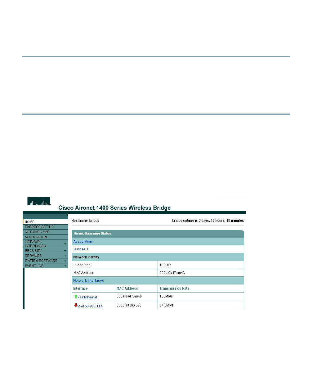
Figure 3 shows the Summary Status page.
Figure 3Summary Status Page
e’s IP address in the browser address line and press Enter. An Enter Network
b to bypass the Username field and advance to the Password field.
ress Enter. The Summary Status page appears.
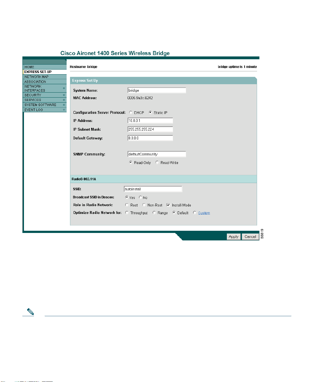
Step 5 Click Express Setup. The Express Setup screen appears. Figure 4 shows the Express Setup
page.
10
Page 11
THIRD FCC DRAFT (CISCO CONFIDENTIAL)
Figure 4 Express Setup Page
Step 6 Enter the configuration settings you obtained from your system administrator. The
configurable settings include:
• System Nam
e—The system name, while not an essential setting, helps identify the bridge
on your network. The system name appears in the titles of the management system pages.
• Config
uration Server Protocol—Click on the button that matches the network’s method
of IP address assignment.
• DHCP—
IP addresses are automatically assigned by your network’s DHCP server.
Note • When DHCP is enabled, the IP Address, Subnet Mask, and Default Gateway fields
indicate Negotiated by DHCP
• Static
IP—The bridge uses a static IP address that you enter in the IP address field.
11
Page 12

THIRD FCC DRAFT (CISCO CONFIDENTIAL)
• IP Address—Use this setting to assign or change the bridge’s IP address. If DHCP is
enabled for your network, leave this field blank.
Note If the bridge’s IP address changes while you are configuring the bridge using the web-browser
interface or a Telnet session over the wired LAN, you lose your connection to the bridge. If
you lose your connection, reconnect to the bridge using its new IP address. Follow the steps
in the “Resetting the Bridge to Default Settings” section on page 7 if you need to start over.
• IP Subn
et Mask—Enter the IP subnet mask provided by your network administrator so
the IP address can be recognized on the LAN. If DHCP is enabled, leave this field blank.
• Default Gateway—
Enter the default gateway IP address provided by your network
administrator. If DHCP is enabled, leave this field blank.
• SNMP Community—
If your network is using SNMP, enter the SNMP Community name
provided by your network administrator and select the attributes of the SNMP data (also
provided by your network administrator).
ad-Only—indicates the bridge allows only SNMP read accesses. Using this option, an
• Re
SNMP user cannot change bridge configuration settings.
• Read-W
rite—indicates the bridge allows SNMP read and write accesses. This setting
allows an SNMP user to change the bridge configuration.
• Rad
io Service Set ID (SSID)—Enter the case-sensitive SSID (32 alphanumeric characters
maximum) provided by your network administrator. The SSID is a unique identifier that
remote bridges use to associate with your bridge.
• Broa
dcast SSID in Beacon—Use this setting to allow devices that do not specify an SSID
to associate with the bridge.
–
Yes—This is the default setting; it allows a remote bridge that does not specify an
SSID to associate with the bridge.
–
No—Remote bridges must specify an SSID to associate with the bridge. With No
selected, the SSID used by the remote bridge must match exactly the bridge’s SSID.
• Role i
n Radio Network—Click on the check box and button that describes the role of the
bridge on your network.
• Insta
ll Mode—Activates the bridge install and alignment mode. Specifies that the bridge
automatically determines the network role. If the bridge is able to associate to another
root bridge within 60 seconds, the bridge assumes a non-root bridge role. If the bridge is
unable to associate with another root bridge within 60 seconds, the bridge assumes a root
bridge role.
You can also pre-configure the bridge into root or non
-root modes and avoid the 60
seconds automatic detection phase.
12
Page 13

THIRD FCC DRAFT (CISCO CONFIDENTIAL)
• Root—Specifies that the bridge connects directly to the main Ethernet LAN network and
accepts associations from other bridges.
• Non-root—Specifies
associate with the root bridge using the wireless interface.
Note When initially powered up, the bridge is configured in Install mode with automatic detection
activated.
that the bridge connects to a remote LAN network and must
• Optimize Radio Networ
the bridge radio or customized settings for the bridge radio.
–
Throughput—Maximizes the data volume handled by the bridge but might reduce its
range.
–
Range—Maximizes the bridge’s range but might reduce throughput.
–
Default—The bridge retains default radio settings that are designed to provide good
range and throughput for most bridges.
–
Custom—The bridge uses settings you enter on the Network Interfaces:
Radio-802.11a Settings page. Clicking Custom takes you to the Network Interfaces:
Radio-802.11a Settings page.
–
Click Apply to save your settings. If you changed the IP address, you lose your
connection to the bridge. Browse to the new IP address to reconnect to the bridge.
Note You can restore the bridge to its factory defaults by unplugging the power injector’s power
jack and plugging it back in while holding down the Mode button for a few seconds, or until
the Status LED turns amber.
k for—Use this setting to select either preconfigured settings for
Default Settings on the Express Setup Page
Table 1 lists the default settings for the settings on the Express Setup page.
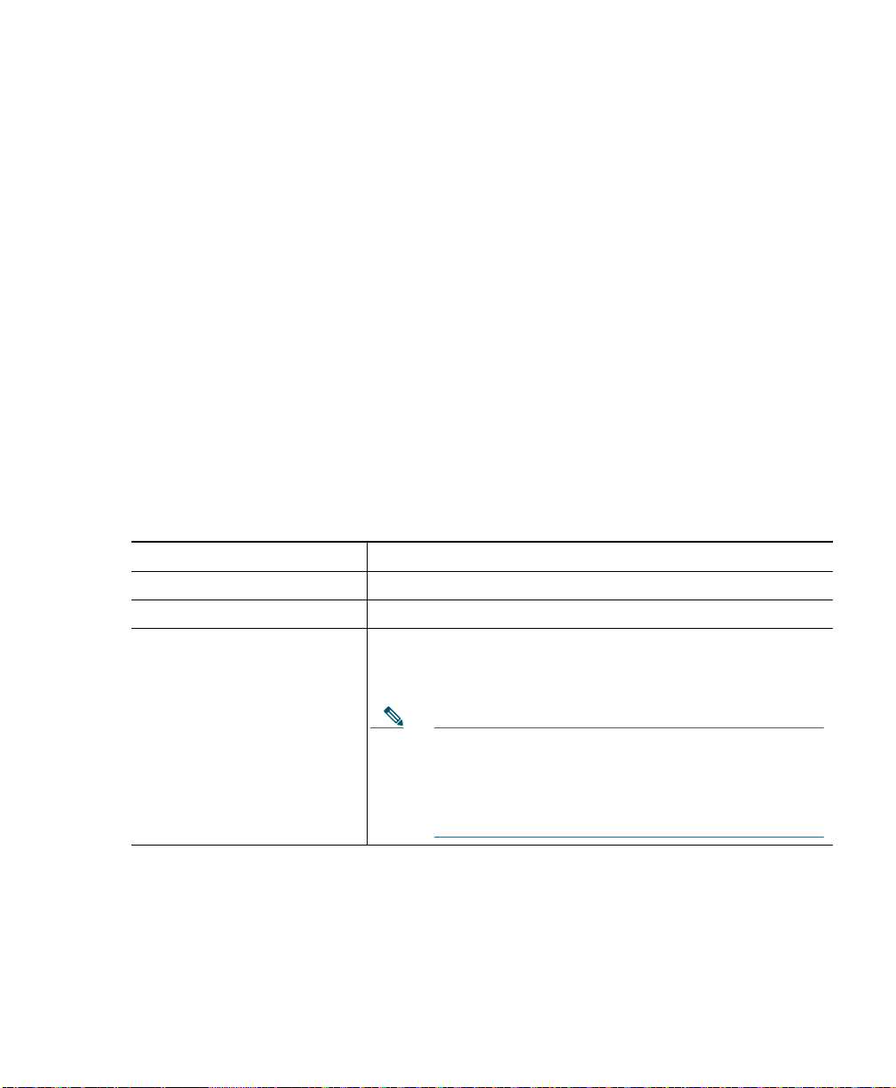
Ta b l e 1 Default Settings on the Express Setup Page
Setting Default
System Name Bridge
Configuration Server Protocol DHCP
13
Page 14

THIRD FCC DRAFT (CISCO CONFIDENTIAL)
Table 1 Default Settings on the Express Setup Page (continued)
Setting Default
IP Address Assigned by DHCP (default setting); if DHCP is disabled, the
defau
lt setting is 10.0.0.1
IP Subnet Mask Assigned by DHCP (default setting); if DHCP is disabled, the
lt setting is 255.255.255.224
defau
Default Gateway Assigned by DHCP (default setting); if DHCP is disabled, the
default s
SNMP defaultCommunity
Read Only
SSID autoinstall
Broadcast SSID in Beacon Yes
Role in Radio Network Install
Optimize Radio Network for Throughput
1. During Install Mode, the SSID is autoinstall.
etting is 0.0.0.0
1
What To Do Next
After your bridge has basic settings, you need to complete your bridge’s configuration. You might need
to adjust the output power level and other network and security settings.
Output Power Level
Your bridge’s output power level might require adjustment under the following conditions:
• When bridges are
to avoid overloading the bridge’s receivers.
To configure your bridge’s output power level, refer to
Aironet Access Points and Bridges.
14
installed less than 328 ft (100 m) apart, you should reduce their output power
the Power Levels and Channels for Cisco
Page 15
THIRD FCC DRAFT (CISCO CONFIDENTIAL)
Protecting Your Wireless LAN
To prevent unauthorized access to your network, you must configure security settings. Because the
bridge is a radio device, the bridge communicates beyond the physical boundaries of your building.
Refer to the Cisco Aironet 1400 Series Wireless Bridge Software Configuration Guide to configure
security features to protect your network from intruders:
• Uniq
• WEP an
• Dyna
ue SSIDs that are not broadcast in the bridge beacon
d additional WEP features, such as TKIP and broadcast key rotation
mic WEP and EAP authentication
Assigning an IP Address Using the CLI
When you connect the bridge to the wired LAN, the bridge links to the network using a bridge virtual
interface (BVI) that it creates automatically. Instead of tracking separate IP addresses for the bridge’s
Ethernet and radio ports, the network uses the BVI.
When you assign an IP address to the bridge using the CLI, you mus
Beginning in privileged EXEC mode, follow these steps to assign an IP address to the bridge’s BVI:
t assign the address to the BVI.
Command Purpose
Step 1
Step 2
Step 3
configure terminal Enter global configuration mode.
interface bvi1 Enter interface configuration mode for the BVI.
ip address address
mask
Assign an IP address and address mask to the BVI. This step
automatically saves the running configuration to the startup
configuration.
Note You lose your connection to the bridge when you
assign a new IP address to the BVI. If you need to
continue configuring the bridge, use the new IP
address to open another Telnet session to the
bridge.
Using a Telnet Session to Access the CLI
Follow these steps to access the CLI using a Telnet session. These steps are for a PC running Microsoft
Windows with a Telnet terminal application. Check your PC operating instructions for detailed
instructions for your operating system.
15
Page 16

THIRD FCC DRAFT (CISCO CONFIDENTIAL)
Step 1 Select Start > Programs > Accessories > Telnet.
If Telnet is not listed in your Accessories menu,
field, and press Enter.
Step 2 When the T
Note In Windows 2000, the Telnet window does not contain drop-down menus. To start
elnet window appears, click Connect and select Remote System.
the Telnet session in Windows 2000, type open followed by the bridge’s IP address.
select Start > Run, type Tel n et in the entry
Step 3 In
the Host Name field, type the bridge’s IP address and click Connect.
6 Mounting the Bridge
This section describes in fundamental terms how to mount the bridge using its supplied mounting
hardware. Detailed mounting instructions are contained in the Cisco Aironet 1430 Wireless Bridge
Mounting Instructions, which shipped with your bridge. This document is also available on cisco.com.
Typically, the bridge is installed on a rooftop, mast, tower
installations requires a different approach. This document provides a mounting overview. For detailed
mounting instructions, refer to the Cisco Aironet 1400 Series Wireless Bridge Mounting Instructions
that shipped with your bridge.
Personnel installing the bridge must understand wireless bridg
adjustment, and grounding methods. The integrated antenna configuration can be installed by an
experienced IT professional.
Mounting Hardware
The bridge is shipped with the following mounting hardware:
• Multi-function mount (cons
• Fastener
hardware (consisting of nuts, bolts, washers, and U-bolts)
isting of two bridge brackets and one mast bracket)
, wall, or a suitable flat surface. Each of these
ing techniques, antenna alignment and
Multi-function Mount
The multi-function mount provides a method for mounting the bridge on a mast, tower, or an optional
roof-mast mount. The multi-function mount permits easy azimuth and elevation adjustments for
antenna alignment purposes. The basic mounting procedure is shown below:
1. Mount the
16
two bridge brackets to the bridge with the support pins facing the sides of the bridge.
Page 17

THIRD FCC DRAFT (CISCO CONFIDENTIAL)
2. Mount the mast bracket to the tower or mast using the supplied U-bolts.
3. Suspend the bridge on
4. Secure the bridge
tighten).
5. Connect the dual-coax cable to the power injector dua
bridge.
Note You should securely tighten the cable connectors (15 to 20 inch-pounds) using a small wrench.
the mast bracket using the bridge bracket support pins.
brackets to the mast bracket using the supplied nuts, bolts, and washers (hand
l-coax ports (F-type connectors) on the
6. Conn
7. Alig
ect the ground wire to the bridge.
n the bridge and tighten the nuts and bolts.
Bridge Brackets
The two bridge brackets mount on the back side of the bridge housing. Each bracket mounts on two
screw posts on opposite ends of the unit. The support pin on the bridge bracket must be facing the side
of the unit. These support pins are used to suspend the bridge in the notches on the mast mounting
bracket until you secure the mounting bolts.
The bridge brackets must be positioned to obtain
remote antenna. The bridge housing contains an antenna polarization mark consisting of an arrow on
the side of the housing. When the bridge is positioned so that the arrow is pointing up, the bridge
antenna is vertically polarized. For horizontal polarization, the arrow should be pointing from left to
right. All bridges must use the same antenna polarization for best operation.
the correct antenna polarization that matches the
Mast Bracket
The mast bracket attaches to a mast or tower support and is used to secure the bridge.The procedure
for attaching the mounting bracket to the support depends on the pipe diameter, as shown in Tab le 2.
Ta b l e 2 Mast Bracket Attachment Methods
Mast Type Mast Diameter Mast Attachment Method
Roof mount,
small mast, or
tower
Large mast 2.5 to 4.5 in.
1.5 to 2.5 in.
(30.5 to 63.5 mm)
(63.5 to115 mm)
Attach the pipe inside the mounting bracket, between
the bracket and bridge.
Attach the pipe outside the mounting b
from the bridge.
racket, away
17
Page 18

THIRD FCC DRAFT (CISCO CONFIDENTIAL)
Note The U-bolts supplied with the bridge support mast diameters up to 1.75 in. (44.5 mm). For
larger masts, you must supply the U-bolts to attach the bridge.
Bridge LEDs
When you power up the bridge for the first time, it starts in a special installation mode. The LEDs
indicate the startup status, operating mode, association status, and received signal strength. This
information simplifies the process of activating the link and positioning the antenna from the bridge
mounting location.
The LEDs are mounted on the back of the ho
Figure 5 LED and Connector Locations
using near the connectors (see Figure 5).
1 Status LED—bridge software status 3 Radio LED—status of 802.11a radio
2 Uplink LED—Ethernet status 4 Install LED—
18
Page 19

THIRD FCC DRAFT (CISCO CONFIDENTIAL)
When the bridge is initially powered-up, installation mode is activated and the bridge attempts to
associate to a root bridge for 60 seconds. If it is unable to associate with a root bridge, it automatically
assumes the root bridge role. The Install LED provides bridge association status during installation
mode as shown in Table 3.
Ta b l e 3 Install LED Association Status
Install LED State Bridge State
Off Self test Startup.
Blinking amber Non-root, searching Not associated (non-root mode). The
bridge
bridge for 60 seconds
Amber Non-root, associated Associated (non-root mode).
Blinking green Root, searching Not associated (root mode). The bridge
attempts to asso
bridge indefinitely.
Green Root, associated Associated (root mode).
1. Preconfigured bridges search indefinitely.
attempts to associate with a root
1
.
ciate with a non-root
Use the Install LED to determine when the br
verify its mode of operation. After association, the other three LEDs indicate signal strength (see
Table 4).
The startup and association sequence depends on the bridge con
following types:
• Defa
• Preco
ult—The bridge attempts to associate with a root bridge for 60 seconds. If it does not
associate with a root bridge, it then attempts to associate with a non-root bridge.
nfigured—The bridge attempts to associate with a remote bridge in the configured mode,
either root or non-root. Because there are no timeouts, it is easier to align the antenna.
idge successfully associates with a remote bridge and to
figuration, which can be one of the
Aligning the Antenna Using LED Indications
You can align the integrated antenna using LEDs after the bridge successfully associates with a remote
bridge. In the installation mode before association to another bridge, the Install LED blinks amber. If
the bridge associates to a root bridge, the Install LED turns continuous amber. If the bridge does not
associate to a root bridge in the first 60 seconds, the Install LED blinks green to indicate beacons are
being transmitted and the bridge is waiting for another non-root bridge to associate. After association,
the Install LED turns into continuous green and the Ethernet, status, and radio LEDs then display
signal strength as shown in Ta b l e 4).
19
Page 20

THIRD FCC DRAFT (CISCO CONFIDENTIAL)
Note For the signal level (dBm), a smaller number represents a stronger signal because the signal
level is given as a negative value.
Ta b l e 4 LED Installation Mode Signal Strength Display
Signal Level (dBm) Uplink LED Status LED Radio LED
>–42 On On On
–45 to –42 Fast blink
–48 to –45 Slow blink
1
2
–51 to –48 Very slow blink
On On
On On
3
On On
–54 to –51 Off On On
–57 to –54 Off Fast blink
–60 to –57 Off Slow blink
1
2
–63 to –60 Off Very s l o w bl ink
On
On
3
On
–66 to –63 Off Off On
–69 to –66 Off Off Fast blink
–72 to –69 Off Off Slow blink
–75 to –72 Off Off Very slow blink
1
2
3
< –75 Off Off Off
1. Fast blink rate is 1 blink/sec.
2. Slow blink rate is 2 blinks/sec.
3. Very slow blink rate is 4 blinks/sec
When using LEDs to maximize the signal, adjust the antenna
until as many LEDs as possible are turned
on and the rest are blinking as fast as possible.
Aligning the Antenna Using the RSSI Voltage
The RSSI port produces a DC voltage that is proportional to the received signal level. The RSSI voltage
is available whenever a signal is present, regardless of the bridge mode (installation or normal),
association status, or pre configuration role setting. In Install mode, the RSSI voltage provides an
20
Page 21

THIRD FCC DRAFT (CISCO CONFIDENTIAL)
instantaneous reading as you move the antenna. In Normal mode, the RSSI reading has a delay, so you
must stop moving the antenna and wait before taking your reading. The RSSI port is a female BNC
connector on the bridge housing (see Figure 5).
The RSSI voltage increases linearly with signal level as shown in Table 5.
Note A larger RSSI voltage reading indicates a stronger signal.
Ta b l e 5 RSSI Voltage Levels
Nominal Signal Level (dBm) RSSI Reading (volts)
–20 or greater 2.70
–30 2.31
–40 1.93
–50 1.54
–60 1.16
–70 0.77
–80 0.39
–90 or less 0.00
The voltage varies from 0 to 2.7 volts for signals between –90 and –20 dBm, respectively. The accuracy
over temp
convenient voltmeter connected to the RSSI port using a cable with a male BNC connector.
erature and component variations is ± 4 dB. To obtain RSSI readings, you can use any
Grounding the Bridge
The bridge must be grounded before you connect power. Your grounding installation must comply
with national and local electrical codes. Follow these steps to ground the bridge to a suitable building
ground.
Step 1 Find a suitable building grounding point as close to the bridge as possible.
Step 2 Conn
Step 3 Route
ect a user-supplied ground wire to the building grounding point. The wire should be a
minimum of #14AWG assuming a circuit length of 25 ft (30.5 cm). Consult your local
electrical codes for additional information.
the ground wire to the bridge.
21
Page 22

THIRD FCC DRAFT (CISCO CONFIDENTIAL)
Step 4 Use a Phillips screw driver to remove grounding post screw on the low-profile mounting
bracket.
Step 5 Attach
Step 6 Crimp or solder the wire to
Step 7 I
mounting plate as shown in Figure 6.
Figure 6
the wire to a suitable grounding O-ring lug.
the lug.
nsert the grounding post screw into the O-ring lug and reinstall it on the low-profile
Step 8 Use a Phillips screw driver to tighten the grounding post screw.
7 Troubleshooting
If you follow the instructions in previous sections of this guide, you should have no trouble getting
your bridge installed and running. If you do experience difficulty, before contacting Cisco, look for a
solution to your problem in this guide or the troubleshooting chapter of the hardware installation
guide for the bridge you are using. These, and other documents, are available on Cisco.com. Follow
these steps to access and download these documents:
Step 1 Open your web browser and go to http://www.cisco.com.
22
Page 23

THIRD FCC DRAFT (CISCO CONFIDENTIAL)
Step 2 Click Products & Services. A pop-up window appears.
Step 3 Click Wi
Step 4 Scroll
Step 5 Under Outdoor W
Introduction page appears.
Step 6 Scroll
Series Install and Upgrade page appears.
Step 7 Click In
page appears.
Step 8 Sel
reless. The Wireless Introduction page appears.
down to the Product Portfolio section.
ireless, click Cisco Aironet 1430 Series. The Cisco Aironet 1430 Series
down to the Support window and click Install and Upgrade. The Cisco Aironet 1430
stall and Upgrade Guides. The Cisco Aironet 1430 Series Install and Upgrade Guides
ect the section that best suits your troubleshooting needs.
Checking the Bridge LEDs
If your bridge is not associating with the remote bridge, check the four LEDs on the back panel. You
can use them to quickly assess the unit’s status. For information on using the LEDs during the
installation and alignment of the bridge antenna, refer to the “Bridge LEDs” section on page 3.
Figure 7 shows the bridge LEDs.
23
Page 24

THIRD FCC DRAFT (CISCO CONFIDENTIAL)
Figure 7 Bridge LEDs
1 Ethernet LED 3 Radio LED
2 Status LED 4 Install LED
Bridge Normal Mode LED Indications
During bridge operation the LEDs provide status information as shown in Table 6.
24
Page 25

THIRD FCC DRAFT (CISCO CONFIDENTIAL)
Ta b l e 6 Bridge Normal Mode LED Indications
Ethernet
LED
Off — — Ethernet link is down or disabled.
Green — — Ethernet link is operational.
Blinking
n
gree
Blinking
r
ambe
amber — — Firmware error—disco
— Blinking
— Green — Root mode—associated to at least one
— Blinking
— Amber — Loading firmware.
Red Amber Red Loading Firmware error—disconne
— — Off Normal operation.
— — Blinking
Status
LED
— — Transmitting and receiving Ethernet packets.
— — Transmitting and receiving Ethernet errors.
gre
en
r
ambe
Radio
Meaning
LED
nnect and reconnect the power
injector power jack. If the problem continues, contact
technical support for assistance.
— Root mode—no remote bridges are associated.
Non-root mode—not associated to the root bridge.
If all bridges are powered up, this could be caused by
i
ncorrect SSID and security settings or improper antenna
alignment. You should check the SSID and security settings
of all bridges and verify antenna alignment.
If the problem continues, contact technical support for
as
sistance.
Non-root mode—associated to the root bridge.
This is normal operation.
— General warning—disconnect and reconnect the power
injector power jack. If the problem continues, contact
technical support for assistance.
ct and reconnect the
power injector power. If the problem continues, contact
technical support for assistance.
Transmitting and receiving radio packets—normal
green
peration.
o
remote bridge.
25
Page 26

THIRD FCC DRAFT (CISCO CONFIDENTIAL)
Table 6 Bridge Normal Mode LED Indications (continued)
Ethernet
LED
— — Blinking
— — Amber Radio firmware error—disconnect and reconnect power
The bridge uses a blinking code to identify various error conditions. The code sequence uses a
two-digit diagnostic code that starts with a long pause to delimit the code, followed by the LED
flashing red to count out the first digit, then a short pause, followed by the LED flashing red to count
out the second digit (see Table 7).
Ta b l e 7 Bridge LED Blinking Error Codes
Status
LED
Radio
LED
amber
Meaning
Maximum retries or buffer full
interface—disconnect and reconnect the power injector
power jack. If the problem continues, contact technical
support for assistance.
i
njector power.If the problem continues, contact technical
support for assistance.
occurred on the radio
Blinking Codes
First
LED
Ethernet 2 1 Ethernet cable problem—verify that the cable is properly
Radio 1 2 Radio not detected—contact technical support for
Digit
1 3 Radio not ready—contact technical support for ass
1 4 Radio did not start—contact technical support for
1 5 Radio failure—contact technical support for assistance.
1 6 Radio did not flash its firmware—contact technical support
Second
Digit
Description
connected and not defective. This error might also indicate
a problem with the Ethernet link. If the cable is connected
properly and not defective, contact technical support for
assistance.
as
sistance.
istance.
sistance.
as
sistance.
for as
26
Page 27

THIRD FCC DRAFT (CISCO CONFIDENTIAL)
Power Injector LEDs
The power injector contains three LEDs to provide status information on the wired Ethernet link, the
bridge Ethernet link, and the bridge status. When the power injector is powered up, it sends a constant
discovery tone on the dual-coax cables to the bridge. When the bridge is connected to the dual-coax
cables, it returns the discovery tone to the power injector. When the power injector detects the returned
discovery tone, it applies +48 VDC to the dual-coax cables to the bridge.
When power is applied to the bridge, the bridge activates the bootloa
operations. The bridge begins to load the IOS image when the Post operations are successfully
completed. Upon successfully loading the IOS image, the bridge initializes and tests the radio.
The power injector LEDs are shown in Figure 8.
Figure 8 Power Injector LEDs
der and begins the POST
1 Power jack (+48 VDC) 5 Ethernet port (RJ–45 connector)
2 Power LED 6 Ethernet Activity LED
3 Power injector dual-coax ports (F-Type connectors) 7 Injector Status LED
4 Mode button 8 Uplink Activity LED
The power injector LED indications are shown in Table 8.
27
Page 28

THIRD FCC DRAFT (CISCO CONFIDENTIAL)
Ta b l e 8 Power Injector LED Indications
Uplink Activity Injector Status Ethernet Activity Description
— — Off Wired LAN Ethernet link is not active.
— — Green Wired LAN Ethernet link is operational.
— — Blinking Green Transmitting and receiving packets over the
LAN Ethernet link.
wired
— — Amber Power injector internal memory
error—disconnect and reconnect the power
injector pow
contact technical support for assistance.
Off — — Link between power injector and bridge is not
acti
ve. This might be caused by improper
connections or a defective cable or connector.
Verify that the dual-coax cables are connected
correctly to the power injector, grounding
block, and bridge. If the cables are connected
correctly, contact technical support for
assistance.
Green — — Link between power injector and bridge is
opera
Blinking Green — — Transmitting and receiving Ethernet packets
betw
een the power injector and the bridge.
Amber — — Power injector internal memory
error—disconnect and reconnect the power
injector pow
contact technical support for assistance.
— Green — Bridge successfully passed Power On Self Test
(POST)
— Blinking Green — Bridge power is active and the bridge is loading
IOS image
er plug. If the problem continues,
tional.
er plug. If the problem continues,
and loaded the IOS image.
or POST operation has started.
28
Page 29

THIRD FCC DRAFT (CISCO CONFIDENTIAL)
Table 8 Power Injector LED Indications (continued)
Uplink Activity Injector Status Ethernet Activity Description
— Blinking Amber —– Bridge has not been detected and bridge power
is not active.
connections or a defective cable or connector.
Verify that the dual-coax cables are connected
correctly to the power injector, grounding
block, and bridge. If the cables are connected
correctly, contact technical support for
assistance.
Amber Amber Amber Power injector internal memory
error—disconnect and reconnect the power
injector pow
contact technical support for assistance.
Off Amber Off Bridge is resetting the configuration to
defa
ults; mode button has been depressed
more than 2 seconds but less than 20 seconds.
— Red — Image recovery mode, downloading new
image; mode button pressed more tha
seconds.
Red Red Red Power injector internal memory
error—disconnect and reconnect the power
injector pow
contact technical support for assistance.
This might be caused by bad
er plug. If the problem continues,
n 20
er plug. If the problem continues,
Checking Power
You can verify the availability of power to the bridge by checking the power injector LEDs (see
Figure 8):
• Power LED
–
Green color indicates 48 VDC is available to the power injector (see Figure 8).
–
Off indicates 48 VDC is not available to the power injector—verify that the power module is
connected to the power injector and to an AC receptacle and that AC power is available.
• Upli
nk Activity LED
–
Green or blinking green color indicates the bridge is operating.
29
Page 30

THIRD FCC DRAFT (CISCO CONFIDENTIAL)
–
Off indicates that the power injector-to-bridge link is not active—verify that the dual-coax
cable connections are properly connected to the power injector, the grounding block, and the
bridge. If the dual-coax cable is connected properly and the cable is not defective, contact
technical support for assistance.
–
Amber color indicates that an internal power injector problem—disconnect and reconnect the
power injector power plug. If the problem continues, contact technical support for assistance
contact technical support for assistance.
• Status LED
–
Green or blinking green color indicates that the bridge is operating.
–
Blinking amber color indicates that the bridge has not been detected by the power injector and
that power is not being supplied to the bridge—verify that the dual-coax cable connectors are
properly connected to the power injector, the grounding block, and the bridge. If the
dual-coax cable is connected properly and not defective, contact technical support for
assistance.
Checking Basic Configuration Settings
Mismatched basic settings are the most common causes of lost wireless connectivity. If the bridge does
not associate with a remote bridge, check the following areas.
SSID
To associate, all bridges must use the same SSID. The bridge installation mode SSID is autoinstall and
the normal mode default SSID is tsunami. You should verify that the SSID value shown on the Express
Setup page is the same for all bridges. You should also verify that the bridges are configured for the
proper network role; only one bridge can be configured as the root bridge.
Security Settings
Remote bridges attempting to authenticate to your bridge must support the same security options
configured in the bridge, such as WEP, EAP or LEAP, MAC address authentication, Message Integrity
Check (MIC), WEP key hashing, and 802.1X protocol versions.
If a non-root bridge is unable to authenticate to your root bridge, verify that the security settings are the
same as your bridge settings.
Antenna Alignment
If your non-root bridges are unable to associate to your root bridge, you should verify the basic
configuration settings on all bridges before attempting to verify bridge antenna alignment (refer to
“Configuring the Bridge for the First Time” section on page 1). If your basic configuration settings are
30
Page 31

THIRD FCC DRAFT (CISCO CONFIDENTIAL)
correct, you can verify antenna alignment by using the RSSI port. The RSSI port can be used even when
the bridges are not associated. For additional information, refer to the “Aligning the Antenna Using
the RSSI Voltage” section on page 6.
Note To meet regulatory restrictions, the external antenna bridge configuration and the external
antenna must be professionally installed.
For detailed alignment instructions, refer to the Ci
Instructions that shipped with your bridge.
sco Aironet 1400 Series Wireless Bridge Mounting
Resetting to the Default Configuration
If you forget the password that allows you to configure the bridge, you may need to completely reset
the configuration. You can use the MODE button on the power injector or the web-browser interface.
Note The following steps reset all configuration settings to factory defaults, including passwords,
WEP keys, the IP address, and the SSID.
Using the MODE Button
Follow these steps to delete the current configuration and return all bridge settings to factory defaults
using the MODE button:
Step 1 Disconnect the power jack on the power injector.
Step 2 Press
Step 3 Hold the MOD
Step 4 After the bridg
and hold the MODE button while you reconnect power to the power injector.
E button until the Status LED turns amber (approximately 3 seconds).
e reboots, you must reconfigure the bridge by using the Web browser interface,
the Telnet interface, or IOS commands.
Note The bridge is configured with the factory default values including the IP address (set
to receive an IP address using DHCP). To obtain the bridge’s new IP address, refer to
the “Using the IP Setup Utility” section on page 9.
31
Page 32

THIRD FCC DRAFT (CISCO CONFIDENTIAL)
Using the Web Browser Interface
Follow the steps below to delete the current configuration and return all bridge settings to the factory
defaults using the web browser interface.
Step 1 Open your Internet browser. You must use Microsoft Internet Explorer (version 5.x or later)
or Netscape Navigator (version 4.x).
Step 2 Enter the bridg
Password screen appears.
Step 3 Enter your username in the User Name
Step 4 Enter the bridg
appears.
Step 5 Click Sy
Step 6 Click Sy
Step 7 Click Default.
Note If the bridge is configured with a static IP address, the IP address does not change.
e’s IP address in the browser address line and press Enter. An Enter Network
field.
e password in the Password field and press Enter. The Summary Status page
stem Software and the System Software screen appears.
stem Configuration and the System Configuration screen appears.
Step 8 After the bridg
the Telnet interface, or IOS commands.
e reboots, you must reconfigure the bridge by using the Web browser interface,
Reloading the Bridge Image
If your bridge has a firmware failure, you must reload the complete bridge image file using the Web
browser interface or by pressing and holding the MODE button for around 30 seconds. You can use
the browser interface if the bridge firmware is still fully operational and you want to upgrade the
firmware image. However, you can use the MODE button when the bridge has a corrupt firmware
image.
Using the MODE button
You can use the MODE button on the bridge to reload the bridge image file from an active Trivial File
Transfer Protocol (TFTP) server on a PC connected directly to the power injector Ethernet port.
32
Page 33

THIRD FCC DRAFT (CISCO CONFIDENTIAL)
Note If your bridge experiences a firmware failure or a corrupt firmware image, indicated by three
red LEDs, you must reload the image from a directly connected PC with a TFTP server.
Note This process resets all configuration settings to factory defaults, including passwords, WEP
keys, the bridge IP address, and SSIDs.
Follow the steps below to reload the bridge image file:
Step 1 The PC you intend to use must be configured with a static IP address in the range of 10.0.0.2
to 10.0.0.30.
Step 2 Mak
Step 3 Conn
Step 4 Discon
Step 5 Press
Step 6 Hold the MOD
Step 7 W
Step 8 After the b
e sure the PC contains the bridge image file (c1410-k9w7-tar.122-13.JA.tar) in the TFTP
server folder and the TFTP server is activated. For additional information, refer to the
“Obtaining the Bridge Image File” and “Obtaining the TFTP Server Software” sections.
ect the PC to the bridge using a Category 5 Ethernet cable.
nect the power jack from the power injector.
and hold the MODE button while you reconnect power to the power injector.
E button until the status LED turns red (approximately 20 to 30 seconds).
ait until the bridge reboots as indicated by all LEDs turning green followed by the Status
LED blinking green.
ridge reboots, you must reconfigure the bridge by using the Web interface, the
Telnet interface, or IOS commands.
Note The bridge is configured with the factory default values including the IP address (set to receive
an IP address using DHCP). To obtain the bridge’s new IP address, refer to the “Using the IP
Setup Utility” section on page 9.
Web Browser Interface
You can also use the Web browser interface to reload the bridge image file. The Web browser interface
supports loading the image file using HTTP or TFTP interfaces.
Note Your bridge configuration is not changed when using the browser to reload the image file.
33
Page 34

THIRD FCC DRAFT (CISCO CONFIDENTIAL)
Browser HTTP Interface
The HTTP interface enables you to browse to the bridge image file on your PC and download the
image to the bridge. Follow the instructions below to use the HTTP interface:
Step 1 Open your Internet browser. You must use Microsoft Internet Explorer (version 5.x or later)
or Netscape Navigator (version 4.x).
Step 2 Enter the bridg
Password screen appears.
Step 3 Enter your username in the User Name
Step 4 Enter the bridg
appears.
Step 5 Click the System So
appears.
Step 6 Click Br
Step 7 Click Upl
For additional information, click the Help i
e’s IP address in the browser address line and press Enter. An Enter Network
field.
e password in the Password field and press Enter. The Summary Status page
ftware tab and then click Software Upgrade. The HTTP Upgrade screen
owse to locate the image file on your PC.
oad.
con on the Software Upgrade screen.
Browser TFTP Interface
The TFTP interface enables you to use a TFTP server on a network device to load the bridge image file.
Follow the instructions below to use a TFTP server:
Step 1 Open your Internet browser. You must use Microsoft Internet Explorer (version 5.x or later)
or Netscape Navigator (version 4.x).
Step 2 Enter the bridg
Password screen appears.
Step 3 Enter your username in the User Name
Step 4 Enter the bridg
appears.
Step 5 Click Sy
Step 6 Click TF
Step 7 Enter the IP addr
34
e’s IP address in the browser address line and press Enter. An Enter Network
field.
e password in the Password field and press Enter. The Summary Status page
stem Software and then click Software Upgrade. The HTTP Upgrade screen appears.
TP Upgrade.
ess for the TFTP server in the TFTP Server field.
Page 35

THIRD FCC DRAFT (CISCO CONFIDENTIAL)
Step 8 Enter the filename for the bridge image file (c1410-k9w7-tar.122-13.JA.tar) in the Upload
New System Image Tar File field. If the file is located in a subdirectory of the TFTP server root
directory, include the relative path of the TFTP server root directory with the filename. If the
file is in the TFTP root directory, enter only the filename.
Step 9 Click Upl
For additional information click the Help icon on
oad.
the Software Upgrade screen.
Obtaining the Bridge Image File
You can obtain the bridge image file from the Cisco.com software center by following these steps:
Step 1 Use your web browser to go to the Cisco Software Center at the following URL:
http://www.cisco.com/public/sw-center/sw-wireless.shtml
Step 2 Sel
Step 3 For the
Step 4 Sel
Step 5 Sel
Step 6 Sel
Step 7 On t
Step 8 Re
Step 9 Sel
Step 10 Sav
ect Option #1: Aironet Wireless Software Selector.
Product Type, select Wireless Bridge and click Submit.
ect 1430 Series for the model number and click Submit.
ect Current Release (Recommended) and click Submit.
ect c1410-k9w7-tar.122-13.JA.tar, which is the bridge image file.
he Encryption Authorization Form, enter the requested information, read the encryption
information, and check the boxes that apply. Click Submit.
ad and accept the terms and conditions of the Software License Agreement.
ect the bridge image file again to download it.
e the file to a directory on your hard drive and then exit the Internet browser.
Obtaining the TFTP Server Software
You can download TFTP server software from several web sites. Cisco recommends the shareware
TFTP utility available at this URL:
http://tftpd32.jounin.net
Follow the instructions on the website for installing and using the utility.
35
Page 36

THIRD FCC DRAFT (CISCO CONFIDENTIAL)
8 Declarations of Conformity and Regulatory Information
This section provides declarations of conformity and regulatory information for the Cisco Aironet
1430 Series Wireless Bridge.
Manufacturers Federal Communication Commission Declaration of Conformity Statement
Tested To Comply
With FCC Standards
FOR HOME OR OFFICE USE
Models Certification Numbers
AIR-BR1430Axx-A-K9 series (AIR-RM1520-58-A-K9) LDK102068
AIR-BR1430Pxx-A-K9 series (AIR-RM1520-49-A-K9) LDK102067
AIR-BR1430Uxx-A-K9 series (AIR-RM1520-56-A-K9) LDK102071
Manufacturer:
Cisco Systems, Inc.
170 West Tasman Drive
San Jose, CA 95134-1706
USA
This device complies with Part 15 rules. Operation is subject to the following two conditions:
8. T
his device may not cause harmful interference, and
9. Thi
This equipment has been tested and found to comply with the limits of a Class B digital device,
pursu
against harmful interference when the equipment is operated in a residential environment. This
equipment generates, uses, and radiates radio frequency energy, and if not installed and used in
36
s device must accept any interference received, including interference that may cause undesired
operation.
ant to Part 15 of the FCC Rules. These limits are designed to provide reasonable protection
Page 37

THIRD FCC DRAFT (CISCO CONFIDENTIAL)
accordance with the instructions, may cause harmful interference. However, there is no guarantee that
interference will not occur. If this equipment does cause interference to radio or television reception,
which can be determined by turning the equipment off and on, the user is encouraged to correct the
interference by one of the following measures:
• Reori
• In
• Connect the equipm
• Consult the dea
Caution The Part 15 radio device operates on a non-interference basis with other devices operating
Caution Within the 5.15 to 5.25 GHz band (5 GHz radio channels 34 to 48) the UNII devices are
ent or relocate the receiving antenna.
crease separation between the equipment and receiver.
ent to an outlet on a circuit different from which the receiver is connected.
ler or an experienced radio/TV technician.
at this frequency when using the integrated antennas. Any changes or modification to the
product not expressly approved by Cisco could void the user’s authority to operate this
device.
restricted to indoor operations to reduce any potential for harmful interference to
co-channel Mobile Satellite System (MSS) operations.
Industry Canada
Canadian Compliance Statement
AIR-BR1430Axx-A-K9 series (AIR-RM1520-58-A-K9) 2461B-102068
AIR-BR1430Pxx-A-K9 series (AIR-RM1520-49-A-K9) 2461B-102067
AIR-BR1430Uxx-A-K9 series (AIR-RM1520-56-A-K9) 2461B-102071
This Class B Digital apparatus meets all the requirements of the Canadian Interference-Causing
Equipment Regulations.
Cet appareil numerique de la classe B respecte les exi
Canada.
gences du Reglement sur le material broilleur du
37
Page 38

THIRD FCC DRAFT (CISCO CONFIDENTIAL)
This device complies with Class B Limits of Industry Canada. Operation is subject to the following
two conditions:
1. T
his device may not cause harmful interference, and
2. Thi
Cisco Aironet Access Points are certified to the requiremen
system operating either partially or completely outdoors may require the user to obtain a license for
the system according to the Canadian regulations. For further information, contact your local Industry
Canada office.
s device must accept any interference received, including interference that may cause undesired
operation.
ts of RSS-210. The use of this device in a
European Community, Switzerland, Norway, Iceland, and Liechtenstein
Models:
AIR-BR1430Uxx-E-K9 series
38
Page 39

THIRD FCC DRAFT (CISCO CONFIDENTIAL)
Declaration of Conformity with Regard to the R&TTE Directive 1999/5/EC
39
Page 40

THIRD FCC DRAFT (CISCO CONFIDENTIAL)
The following standards were applied:
• Rad
• EMC—
• Safety
40
io—EN 301.893
EN 301.489-1, EN 301.489-17
—EN 60950-1
Page 41

THIRD FCC DRAFT (CISCO CONFIDENTIAL)
Note This equipment is intended to be used in all EU and EFTA countries. Outdoor use may be
restricted to certain frequencies and/or may require a license for operation. For more details,
contact Cisco Corporate Compliance.
The following CE mark is affixed to the bridge with a 2.4-GHz radio and a 54-Mb/s, 5-GHz radio:
Declaration of Conformity for RF Exposure
United States
This system has been evaluated for RF exposure for Humans in reference to ANSI C 95.1 (American
National Standards Institute) limits. The evaluation was based on ANSI C 95.1 and FCC OET Bulletin
65C rev 01.01. The minimum separation distance from the antenna to maintain compliance for a
general bystander is as follows:
• AIR-BR1430Axx Series: 78.6 inches (
• AIR-BR1430Pxx Seri
• AIR-BR1430Uxx S
es: 19.7 inches (50cm)
eries: 7.9 inches (20cm)
200cm)
Canada
This system has been evaluated for RF exposure for Humans in reference to ANSI C 95.1 (American
National Standards Institute) limits. The evaluation was based on RSS-102 Rev 2. The minimum
separation distance from the antenna to to maintain compliance for a general bystander is as follows:
• AIR-BR1430Axx Series: 78.6 inches (
• AIR-BR1430Pxx Seri
• AIR-BR1430Uxx S
es: 19.7 inches (50cm)
eries: 7.9 inches (20cm)
200cm)
European Union
This system has been evaluated for RF exposure for Humans in reference to the ICNIRP (International
Commission on Non-Ionizing Radiation Protection) limits. The evaluation was based on the EN
50385 Product Standard to Demonstrate Compliance of Radio Base stations and Fixed Terminals for
41
Page 42

THIRD FCC DRAFT (CISCO CONFIDENTIAL)
Wireless Telecommunications Systems with basic restrictions or reference levels related to Human
Exposure to Radio Frequency Electromagnetic Fields from 300 MHz to 40 GHz. The minimum
separation distance from the antenna to maintain compliance for a general bystander is as follows:
Australia
This system has been evaluated for RF exposure for Humans as referenced in the Australian Radiation
Protection standard and has been evaluated to the ICNIRP (International Commission on
Non-Ionizing Radiation Protection) limits. The minimum separation distance from the antenna to a
general bystander is as follows:
• AIR-BR1430Axx Series: 78.6 inches (
• AIR-BR1430Uxx S
eries: 7.9 inches (20cm)
200cm)
Declaration of Conformity Statements
All the Declaration of Conformity statements related to this product can be found at the following
location: http://www.ciscofax.com
9 Bridge Specifications
Table 9 lists the technical specifications for the 1430 series bridge.
Ta b l e 9 1430 Series Bridge Specifications
Category Specification
Dimensions (LxWxD)
Wei g h t
Operating temperature
Storage temperature
Humidity
Antenna
Compliance
42
The 1430 series bridge complies with UL 2043 for products installed in a
building’s environmental air handling spaces, such as above suspended
ceilings.
Page 43

THIRD FCC DRAFT (CISCO CONFIDENTIAL)
Table 9 1430 Series Bridge Specifications (continued)
Category Specification
Safety UL 60950-1
CAN/CSA C22.2 No. 60950-1
IEC 60950-1 with all national deviations
EN 60950-1
UL 2043
EMI and Susceptibility FCC Part 15.107 and 15.109 Class B
ICES-003 Class B Canada
EN 55022 Class B
EN 55024
AS/NZS 3548 Class B
Radio FCC Part 15.247, 15.407
Industry Canada RSS-102
EN 301.893 (Europe)
AS 4268.2 (Australia)
FCC Bulletin OET-65C
Maximum power and
channel settings
Maximum power and the channels allowed in your regulatory domain,
refer
to Channels and Maximum Power Settings for Cisco Aironet
Autonomous Access Points and Bridges. This document is available on
cisco.com.
43
Page 44

THIRD FCC DRAFT (CISCO CONFIDENTIAL)
44
Page 45

THIRD FCC DRAFT (CISCO CONFIDENTIAL)
45
Page 46

THIRD FCC DRAFT (CISCO CONFIDENTIAL)
46
Page 47

THIRD FCC DRAFT (CISCO CONFIDENTIAL)
47
Page 48

THIRD FCC DRAFT (CISCO CONFIDENTIAL)
Americas Headquarters
Cisco Systems, Inc.
170 West Tasman Drive
San Jose, CA 95134-1706
USA
www.cisco.com
Tel: 408 526-4000
800 553-NETS (6387)
Fax: 408 527-0883
Cisco has more than 200 offices worldwide. Addresses, phone numbers, and fax numbers are listed on the
CCDE, CCENT, Cisco Eos, Cisco Lumin, Cisco Nexus, Cisco StadiumVision, Cisco TelePresence, Cisco WebEx, the Cisco logo, DCE,
and Welcome to the Human Network are trademarks; Changing the Way We Work, Live, Play, and Learn and Cisco Store are service
marks; and Access Registrar, Aironet, AsyncOS, Bringing the Meeting To You, Catalyst, CCDA, CCDP, CCIE, CCIP, CCNA, CCNP,
CCSP, CCVP, Cisco, the Cisco Certified Internetwork Expert logo, Cisco IOS, Cisco Press, Cisco Systems, Cisco Systems Capital, the
Cisco Systems logo, Cisco Unity, Collaboration Without Limitation, EtherFast, EtherSwitch, Event Center, Fast Step, Follow Me
Browsing, FormShare, GigaDrive, HomeLink, Internet Quotient, IOS, iPhone, iQuick Study, IronPort, the IronPort logo, LightStream,
Linksys, MediaTone, MeetingPlace, MeetingPlace Chime Sound, MGX, Networkers, Networking Academy, Network Registrar,
PCNow, PIX, PowerPanels, ProConnect, ScriptShare, SenderBase, SMARTnet, Spectrum Expert, StackWise, The Fastest Way to
Increase Your Internet Quotient, TransPath, WebEx, and the WebEx logo are registered trademarks of Cisco Systems, Inc. and/or its
affiliates in the United States and certain other countries.
All other trademarks mentioned in this document or website are the property of their respective owners. The use of the word partner does
not imply a partnership relationship between Cisco and any other company. (0809R)
© 2008 Cisco Systems, Inc. All rights reserved.
Printed in the USA on recycled paper containing 10% postconsumer waste.
Cisco Website at www.cisco.com/go/offices.
Asia Pacific Headquarters
Cisco Systems (USA) Pte. Ltd.
168 Robinson Road
#28-01 Capital Tower
Singapore 068912
www.cisco.com
Tel: +65 6317 7777
Fax: +65 6317 7799
Europe Headquarters
Cisco Systems International BV
Haarlerbergpark
Haarlerbergweg 13-19
1101 CH Amsterdam
The Netherlands
www-europe.cisco.com
Tel: 31 0 800 020 0791
Fax: 31 0 20 357 1100
 Loading...