

Page 1

Cisco Aironet 1240AG Series Access Point
Hardware Installation Guide
April 2007
Americas Headquarters
Cisco Systems, Inc.
170 West Tasman Drive
San Jose, CA 95134-1706
USA
http://www.cisco.com
Tel: 408 526-4000
800 553-NETS (6387)
Fax: 408 527-0883
Text Part Number: OL-8371-05
Page 2

THE SPECIFICATIONS AND INFORMATION REGARDING THE PRODUCTS IN THIS MANUAL ARE SUBJECT TO CHANGE WITHOUT NOTICE. ALL
STATEMENTS, INFORMATION, AND RECOMMENDATIONS IN THIS MANUAL ARE BELIEVED TO BE ACCURATE BUT ARE PRESENTED WITHOUT
WARRANTY OF ANY KIND, EXPRESS OR IMPLIED. USERS MUST TAKE FULL RESPON SIBILITY FOR THEIR APPLICA TION OF ANY PRODUCT S.
THE SOFTWARE LICENSE AND LIMITED WARRANTY FOR THE ACCOMPANYING PRODUCT ARE SET FORTH IN THE INFORM ATION PACKET THAT
SHIPPED WITH THE PRODUCT AND ARE INCORPORATED HEREIN BY THIS REFERENCE. IF YOU ARE UNABLE TO LOCATE THE SOFT WARE LICENSE
OR LIMITED WARRANTY, CONTACT YOUR CISCO REPRESENTATIVE FOR A COPY.
The following information is for FCC compliance of Class A devices: This equipment has been tested and found to comply with the limits for a Class A digital device, pursuant
to part 15 of the FCC rules. These limits are designed to provide reasonable protection against harmful interference when the equipment is operated in a commercial
environment. This equipment generates, uses, and can radiate radio-frequency energy and, if not installed and used in accordance with the instruction manual, may cause
harmful interference to radio communications. Operation of this equipment in a residential area is likely to cause harmful interference, in which case users will be required
to correct the interference at their own expense.
The following information is for FCC compliance of Class B devices: The equipment described in this manual generates and may radiate radio-frequency energy. If it is not
installed in accordance with Cisco’s installation instructions, it may cause interference with radio and television reception. This equipment has been tested and found to
comply with the limits for a Class B digital device in accordance with the specifications in part 15 of the FCC rules. These specifications are designed to provide reasonable
protection against such interference in a residential installation. However, there is no guarantee that interference will not occur in a particular installation.
Modifying the equipment without Cisc o’s writ ten author ization m ay resul t in the equi pment no lo nger comp lyi ng with FCC requi rements for Class A or Class B digital
devices. In that event, your right to use the equ ipment may be limit ed by FCC regul ations , and you may be required to correct a ny interference to radio or television
communications at your own expense.
You can determine whether your equipment is causing interference by turning it off. If the interference stops, it was probab ly caused by the Cisco equipment or one of its
peripheral devices. If the equipment causes interference to radio or television reception, try to correct the interference by using one or more of the following meas ures:
• Turn the television or radio antenna unt il the int erference st ops.
• Move the equipment to one side or the other of the tel evisio n or radi o.
• Move the equipment farther away from the televi sion or radio.
• Plug the equipment into an outlet that is on a di fferent cir cuit from the televi sion o r radio. (That is, make certain th e equipment and the te levision or radio are on circuit s
controlled by different circuit breaker s o r fu ses.)
Modifications to this product no t author ized by Ci sco Syst ems, Inc. coul d voi d the FCC appro val and negate your authorit y to op erate the pr odu ct.
The Cisco implementation of TCP head er compressi on is an adap tation of a program developed by the Universi ty of Ca lifornia, Berk eley (UCB) as part of UCB ’s public
domain version of the UNIX operatin g system. All rights reserved . Copyri ght © 1981 , Rege nts of the Uni versity of Califor nia.
NOTWITHSTANDING ANY OTHER WARRANTY HEREIN, ALL DOCUMENT FILES AN D SOFTWARE OF THESE SUPP LIERS ARE PROVIDED “AS IS” WITH
ALL FAULTS. CISCO AND THE ABOVE-NAMED SUPPLIERS DISCLAI M ALL WARRANTIE S, EXPRESSED OR IMPLIED, INCLUDING, WITHOUT
LIMITATION, THOSE OF MERCHANTABILITY, FITNESS FOR A PARTICULAR PURPOSE AND NO NINFRINGEME NT OR ARISING FROM A COURS E OF
DEALING, USAGE, OR TRADE PRACTICE.
IN NO EVENT SHALL CISCO OR ITS SUPPLIERS BE LIABLE FOR ANY INDIRECT, SPECIAL, CONSEQUENTIAL, OR INCIDENTAL DAMAGES, INCLUDING,
WITHOUT LIMITATION, LOST PROFITS OR LOSS OR DAMAGE TO DATA ARISING OUT OF THE USE OR INABILITY TO USE THIS MANUAL, EVEN IF CISCO
OR ITS SUPPLIERS HAVE BEEN ADVISED OF THE POSSIBILITY OF SUCH DAMAGES .
CCVP, the Cisco Logo, and the Cisco Square Bridge logo are trademarks of Cisco Systems, Inc.; Changing the Way We Work, Live, Play, and Learn is a service mark of Cisco Systems,
Inc.; and Access Registrar, Aironet, BPX, Catalyst, CCDA, CCDP, CCIE, CCIP, CCNA, CCNP, CCSP, Cisco, the Cisco Certified Internetwork Expert logo, Cisco IOS, Cisco
Press, Cisco Systems, Cisco Systems Capital, the Cisco Systems logo, Cisco Unity, Enterprise/Solver, EtherChannel, EtherFast, EtherSwitch, Fast Step, Follow Me Browsing,
FormShare, GigaDrive, GigaStack, HomeLink, Internet Quotient, IOS, iPhone, IP/TV, iQ Expertise, the iQ logo, iQ Net Readiness Scorecard, iQuick Study, LightStream,
Linksys, MeetingPlace, MGX, Networking Academy, Network Registrar, Pack e t, PIX, ProConnect, RateMUX, ScriptShare, SlideCast, SMARTnet, StackWise, The Fastest Way
to Increase Your Internet Quotient, and TransPath are registered trademarks of Cisco Systems, Inc. and/or its affiliates in the United States and certain other countries.
All other trademarks mentioned in this document or Website are the property of their respective owners. The use of the word partner does not imply a partnership relationship
between Cisco and any other company. (0612R)
Any Internet Protocol (IP) addresses used in this document are not intended to be actual addresses. Any examples, command display output, and figures included in the
document are shown for illustrative pur poses onl y. Any use of act ual IP addr ess es in ill ustr ativ e conte nt is uninte ntio nal and coincident al.
Cisco Aironet 1240AG Series Access Point Hardware Installation Guide
© 2007 Cisco Systems, Inc. All rights rese rved.
Page 3

CONTENTS
Preface ix
Audience ix
Purpose ix
Organization ix
Conventions x
Related Publications xii
Locating the Product Serial Number xiii
Obtaining Documentation, Obtaining Support, and Security Guidelines xiv
CHAPTER
1 Overview 1-1
Product Terminology 1-1
Autonomous Access Points 1-1
Lightweight Access Points 1-2
Guidelines for Using Cisco Aironet Lightweight Access Points 1-2
Hardware Features 1-3
Network Examples with Autonomous Access Points 1-8
Root Access Point on a Wired LAN 1-9
Repeater Unit that Extends Wireless Range 1-10
Central Unit in an All-Wireless Network 1-11
Bridge Network with Wireless Clients 1-11
Point-to-Point Bridge Configuration 1-12
Workgroup Bridge Network 1-12
Single or Dual-Radio Operation 1-5
Antennas Supported 1-5
Ethernet Port 1-5
Console Port 1-5
LEDs 1-6
Power Sources 1-6
UL 2043 Certification 1-7
Anti-Theft Features 1-7
OL-8371-05
Network Example with Lightweight Access Points 1-13
Cisco Aironet 1240AG Series Access Point Hardware Installation Guide
iii
Page 4

Contents
CHAPTER
2 Installing the Access Point 2-1
Safety Information 2-2
FCC Safety Compliance Statement 2-2
General Safety Guidelines 2-2
Warnings 2-2
Unpacking the Access Point 2-3
Package Contents 2-3
Basic Installation Guidelines 2-4
Controller Discovery Process for Lightweight Access Points 2-4
Deploying the Access Points on the Wireless Network 2-5
Access Point Layout and Connectors 2-6
Mounting Overview 2-7
Mounting on a Horizontal or Vertical Surface 2-9
Mounting Below a Suspended Ceiling 2-10
Mounting Above a Suspended Ceiling 2-11
Mounting Access Point on a Desktop or Shelf 2-14
Cable Security Bracket 2-14
Removing the Cable Security Bracket 2-15
CHAPTER
Attaching the Access Point to the Mounting Plate 2-16
Securing the Access Point 2-17
Using a Security Cable 2-17
Securing the Access Point to the Mounting Plate 2-18
Connecting the Ethernet and Power Cables 2-20
Connecting to an Ethernet Network with an Inline Power Source 2-21
Connecting to an Ethernet Network with Local Power 2-22
Powering Up the Access Point 2-22
3 Troubleshooting 1240AG Series Autonomous Access Points 3-1
Checking the Lightweight Access Point LEDs 3-2
Checking Basic Settings 3-3
Default IP Address Behavior 3-4
Enabling the Radio Interfaces 3-4
SSID 3-4
WEP Keys 3-4
Security Settings 3-5
Low Power Condition 3-5
Intelligent Power Management 3-6
iv
Cisco Aironet 1240AG Series Access Point Hardware Installation Guide
OL-8371-05
Page 5

Inline Power Status Messages 3-7
Configuring Power Using the CLI 3-9
Issuing the Cisco IOS Command Using the CLI 3-10
Configuring the Access Point System Power Settings Using a Browser 3-11
Running the Carrier Busy Test 3-13
Running the Ping Test 3-14
Resetting to the Default Configuration 3-14
Using the MODE Button 3-15
Using the Web Browser Interface 3-15
Reloading the Access Point Image 3-16
Using the MODE Button 3-16
Web Browser Interface 3-17
Browser HTTP Interface 3-17
Browser TFTP Interface 3-18
Contents
CHAPTER
Obtaining the Access Point Image File 3-19
Connecting to the Access Point Locally 3-20
Obtaining the TFTP Server Software 3-20
4 Troubleshooting 1240AG Series Lightweight Access Points 4-1
Guidelines for Using Cisco Aironet Lightweight Access Points 4-2
Using DHCP Option 43 4-2
Checking the Lightweight Access Point LEDs 4-3
Low Power Condition for Lightweight Access Points 4-5
Intelligent Power Management 4-5
Configuring Power Using Controller CLI Commands 4-6
Manually Configuring Controller Information Using the Access Point CLI 4-7
Configuring Controller Information 4-8
Clearing Manually Entered Controller Information 4-8
Manually Resetting the Access Point to Defaults 4-8
Returning the Lightweight Access Point to Autonomous Mode 4-9
Using a Controller to Return the Access Point to Autonomous Mode 4-9
Using the MODE Button to Return the Access Point to Autonomous Mode 4-9
MODE Button Setting 4-10
OL-8371-05
Obtaining the Autonomous Access Point Image File 4-10
Connecting to the Access Point Locally 4-11
Obtaining the TFTP Server Software 4-12
Cisco Aironet 1240AG Series Access Point Hardware Installation Guide
v
Page 6

Contents
APPENDIX
APPENDIX
A Translated Safety Warnings A-1
B Declarations of Conformity and Regulatory Information B-1
Manufacturers Federal Communication Commission Declaration of Conformity Statement B-2
VCCI Statement for Japan B-3
Department of Communications—Canada B-4
Canadian Compliance Statement B-4
European Community, Switzerland, Norway, Iceland, and Liechtenstein B-4
Declaration of Conformity with Regard to the 1999/5/EC (R&TTE Directive) B-5
Declaration of Conformity for RF Exposure B-7
Guidelines for Operating Cisco Aironet Access Points in Japan B-8
Japanese Translation B-8
English Translation B-8
Administrative Rules for Cisco Aironet Access Points in Taiwan B-9
Access Points with IEEE 802.11a Radios B-9
Chinese Translation B-9
English Translation B-9
All Access Points B-10
Chinese Translation B-10
English Translation B-10
APPENDIX
APPENDIX
APPENDIX
APPENDIX
APPENDIX
Declaration of Conformity Statements B-11
Declaration of Conformity Statements for European Union Countries B-11
C Access Point Specifications C-1
D Channels and Maximum Power Levels D-1
E Console Cable Pinouts E-1
Overview E-2
Console Port Signals and Pinouts E-2
F Priming Lightweight Access Points Prior to Deployment F-1
G Configuring DHCP Option 43 for Lightweight Access Points G-1
Overview G-2
Configuring Option 43 for 1000 Series Access Points G-3
Configuring Option 43 for 1100, 1130, 1200, 1240, and 1300 Series Lightweight Access Points G-4
vi
Cisco Aironet 1240AG Series Access Point Hardware Installation Guide
OL-8371-05
Page 7

G
LOSSARY
I
NDEX
Contents
OL-8371-05
Cisco Aironet 1240AG Series Access Point Hardware Installation Guide
vii
Page 8

Contents
viii
Cisco Aironet 1240AG Series Access Point Hardware Installation Guide
OL-8371-05
Page 9

Audience
Preface
This guide is for the networking professional who installs and manages the Cisco Aironet 1240AG Series
Access Point. The 1 240AG series ac cess poi nt is available in auton omo us an d ligh twei ght
configurations.
To use this guide with autonomous access points, you should have experience working with Cisco IOS
software and be familiar with the concepts and terminology of wireless local area networks.
To use this guide wit h light weigh t a cce ss po ints, you sh ould have experienc e worki ng with a Ci sco
Wireless LAN Controller and be familiar w ith the con cepts an d termin ology of wire less local ar ea
networks.
Purpose
This guide provides the infor mation you need to insta ll your au tonomou s or ligh tweight ac cess poin t.
For detailed information about Cisco IOS commands used with autonomous access points, refer to the
Cisco IOS Command Reference for Cisco Aironet Access Points and Bridges for this release. For
information about the standard Cisco IOS Release 12.3 commands, refer to the Cisco IOS documentation
set available from the Cisco.com home page at Technical Support & Documentation. On the Technic al
Support & Documentation home page, click Cisco IOS Software > Cisco IOS Software Releases 12.3
Mainline.
For information about Cisco Wireless LAN Controllers, refer to the Cisco documentation sets available
from the Cisco.com h ome pa ge at Technical Support & Documentation. On the Technical Su ppo rt &
Documentation hom e page, cli ck Wireless and the documentation is listed under the “Wireless LAN
Controllers” section.
Organization
This guide is organized into these chapters:
Chapter 1, “Overview,” lists the software and hardware features of the access point and describes the
access point’s role in your networ k.
Chapter 2, “Installing the Access Point,” describes how to mount the access point on a desktop, wall, or
ceiling, how to con ne ct Et her net , seri al, an d power cables, and provi des an in st alla tio n sum ma ry, safety
warnings, and general gui deline s.
OL-8371-05
Cisco Aironet 1240AG Series Access Point Hardware Installation Guide
ix
Page 10

Conventions
Preface
Chapter 3, “Troubleshooting 124 0AG Series Autonomous Acce ss Points,” provides trouble shootin g
procedures for basic probl ems with the aut onomous ac cess point.
Chapter 4, “Troubleshooting 1240AG Series Light weight Acce ss Points,” provides troub lesh ooting
procedures for basic pr oblems with the lightwe ight acce ss point.
Appendix A, “Translated Safety Warnings,” provides translations of the safety warnings that appear in
this publication.
Appendix B, “D ecl ara tio ns of Conf or mity and Regula tory I nfo rm ation, ” provides declarations of
conformity and regulatory information for the access point.
Appendix C, “Access Point Specifications,” lists technical specifications for the access point.
Appendix D, “Channels and Maximum Power Levels,” lists the autonomous access point radio channels
and the maximum power levels supported by the world’s regulatory domains.
Appendix E, “Conso le Cable Pinout s,” identifies the pinouts for the serial console cable that connects
to the access point’s serial console port.
Appendix F, “Priming Lightweight Access Points Prior to Dep loyment,” desc ribe s th e pro cedu re to
prime access points with controller information.
Appendix G, “Configuring DHCP Option 43 for Lightweight Access Points,” describes the procedure to
configure DHCP Option 43 for lig htwei ght acce ss points.
Conventions
This publication use s the se conventions to co nvey instructions a nd info rma tion:
Command descriptions use th ese conventions:
Interactive examples use these conventions:
Notes, cautions, and timesavers use these conventions and symbols:
Tip Means the following will help you solve a problem. The tips information might not be troubleshooting
or even an action, but cou ld b e useful info rma tion.
• Commands and keywords are in boldfac e text.
• Arguments for which you supply values are in it alic.
• Square brackets ([ ]) mean optional elements.
• Braces ({ }) group required choices, and vertical bars ( | ) separate the alternative elements.
• Braces and vertical bars within square brackets ([{ | }]) mean a required choice within an optional
element.
• Terminal sessions and system displays are in screen font.
• Information you ent er i s in boldface screen font.
• Nonprinting charac ters, such as passwords or tab s, are i n angle bra ckets (< >) .
Note Means reader take note. Notes contain helpful suggestions or references to materials not contained in
this manual.
Cisco Aironet 1240AG Series Access Point Hardware Installation Guide
x
OL-8371-05
Page 11

Preface
Conventions
Caution Means reader be careful. In this situation, you might do something that could result equipment damage
or loss of data.
Warning
Waarschuwing
Varoitus
Attention
Warnung
This warning symbol means danger. You are in a situation that could cause bodily injury. Before you
work on any equipment, be aware of the hazards involved with electrical circuitry and be familiar
with standard practices for preventing accidents. (To see translations of the warnings that appear
in this publication, refer to the appendix “Translated Safety Warnings.”)
Dit waarschuwingssymbool betekent gevaar. U verkeert in een situatie die lichamelijk letsel kan
veroorzaken. Voordat u aan enige apparatuur gaat werken, dient u zich bewust te zijn van de bij
elektrische schakelingen betrokken risico’s en dient u op de hoogte te zijn van standaard
maatregelen om ongelukken te voorkomen. (Voor vertalingen van de waarschuwingen die in deze
publicatie verschijnen, kunt u het aanhangsel “Translated Safety Warnings” (Vertalingen van
veiligheidsvoorschriften) raadplegen.)
Tämä varoitusmerkki merkitsee vaaraa. Olet tilanteessa, joka voi johtaa ruumiinvammaan. Ennen
kuin työskentelet minkään laitteiston parissa, ota selvää sähkökytkentöihin liittyvistä vaaroista ja
tavanomaisista onnettomuuksien ehkäisykeinoista. (Tässä julkaisussa esiintyvien varoitusten
käännökset löydät liitteestä "Translated Safety Warnings" (käännetyt turvallisuutta koskevat
varoitukset).)
Ce symbole d’avertissement indique un danger. Vous vous trouvez dans une situation pouvant
entraîner des blessures. Avant d’accéder à cet équipement, soyez conscient des dangers posés par
les circuits électriques et familiarisez-vous avec les procédures courantes de prévention des
accidents. Pour obtenir les traductions des mises en garde figurant dans cette publication, veuillez
consulter l’annexe intitulée « Translated Safety Warnings » (Traduction des avis de sécurité).
Dieses Warnsymbol bedeutet Gefahr. Sie befinden sich in einer Situation, die zu einer
Körperverletzung führen könnte. Bevor Sie mit der Arbeit an irgendeinem Gerät beginnen, seien Sie
sich der mit elektrischen Stromkreisen verbundenen Gefahren und der Standardpraktiken zur
Vermeidung von Unfällen bewußt. (Übersetzungen der in dieser Veröffentlichung enthaltenen
Warnhinweise finden Sie im Anhang mit dem Titel “Translated Safety Warnings” (Übersetzung der
Warnhinweise).)
Avvertenza
OL-8371-05
Advarsel
Questo simbolo di avvertenza indica un pericolo. Si è in una situazione che può causare infortuni.
Prima di lavorare su qualsiasi apparecchiatura, occorre conoscere i pericoli relativi ai circuiti
elettrici ed essere al corrente delle pratiche standard per la prevenzione di incidenti. La traduzione
delle avvertenze riportate in questa pubblicazione si trova nell’appendice, “Translated Safety
Warnings” (Traduzione delle avvertenze di sicurezza).
Dette varselsymbolet betyr fare. Du befinner deg i en situasjon som kan føre til personskade. Før du
utfører arbeid på utstyr, må du være oppmerksom på de faremomentene som elektriske kretser
innebærer, samt gjøre deg kjent med vanlig praksis når det gjelder å unngå ulykker. (Hvis du vil se
oversettelser av de advarslene som finnes i denne publikasjonen, kan du se i vedlegget "Translated
Safety Warnings" [Oversatte sikkerhetsadvarsler].)
Cisco Aironet 1240AG Series Access Point Hardware Installation Guide
xi
Page 12

Related Publications
Preface
Aviso
¡Advertencia!
Varning!
Este símbolo de aviso indica perigo. Encontra-se numa situação que lhe poderá causar danos
fisicos. Antes de começar a trabalhar com qualquer equipamento, familiarize-se com os perigos
relacionados com circuitos eléctricos, e com quaisquer práticas comuns que possam prevenir
possíveis acidentes. (Para ver as traduções dos avisos que constam desta publicação, consulte o
apêndice “Translated Safety Warnings” - “Traduções dos Avisos de Segurança”).
Este símbolo de aviso significa peligro. Existe riesgo para su integridad física. Antes de manipular
cualquier equipo, considerar los riesgos que entraña la corriente eléctrica y familiarizarse con los
procedimientos estándar de prevención de accidentes. (Para ver traducciones de las advertencias
que aparecen en esta publicación, consultar el apéndice titulado “Translated Safety Warnings.”)
Denna varningssymbol signalerar fara. Du befinner dig i en situation som kan leda till personskada.
Innan du utför arbete på någon utrustning måste du vara medveten om farorna med elkretsar och
känna till vanligt förfarande för att förebygga skador. (Se förklaringar av de varningar som
förekommer i denna publikation i appendix "Translated Safety Warnings" [Översatta
säkerhetsvarningar].)
Related Publications
These documents provide informa tion abo ut the auto nomous acc ess point :
• Release Notes for Cisco Aironet Access Points
• Cisco IOS Command Reference for Cisco Aironet Access Points and Bridges
• Cisco IOS Software Configuration Guide for Cisco Aironet Access Points
These documents pr ovide inf orm a tion a bo ut t he ligh twe ight ac cess po int and th e c ontr oll er:
• Release Notes for Cisco Wireless LAN Controllers and Lightweight Access Points
• Cisco IOS Software Configuration Guide for Cisco Aironet Access Points
Click this link to browse to the Cisco Wireless documentation home pa ge:
http://www.cisco.com/en/US/products/hw/wireless/tsd_produ cts_supp ort_cat egory_home.html
T o bro wse to the 1240AG series access point documentation, click Cisco Aironet 1240AG Series listed
under “Wireless LAN Access.”
T o browse to the Cisco W ireless LAN Controller docu mentation, click Cisco 4400 Series Wireless LAN
Controllers or Cisco 2000 Series Wireless LAN Controllers listed under “W ir eless LAN Controller s.”
xii
Cisco Aironet 1240AG Series Access Point Hardware Installation Guide
OL-8371-05
Page 13
Preface
CAUTION
Hot
Surfaces
Locating the Product Serial Number
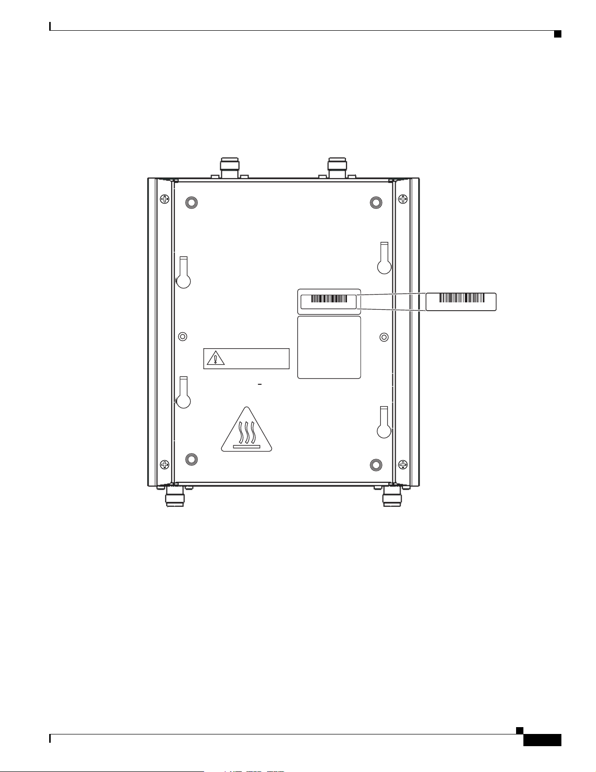
The access point serial number is on the bottom of the housing (refer to Figure 1).
Figure 1 Location of Serial Number Label
Locating the Product Serial Number
SN: NNNNNNNN
135531, 781-00426-01 A0
The access point serial number label contains the following information:
• Model number, such as AIR -AP1 242AG-A-k9 or AI R-LAP 1242AG-A-k9
• Serial number, such as VDF0636XXX X (11 alpha numeric digi ts)
• MAC address, such as 00abc65094f3 (12 hexadecimal digits)
SN: NNNNNNNN
OL-8371-05
• Location of manufactu re, such as Made in Singapore
You need your product serial number when re questing sup port from the Cisco Technical Assistance
Center.
Cisco Aironet 1240AG Series Access Point Hardware Installation Guide
xiii
Page 14

Obtaining Documentation, Obtaining Support, and Security Guidelines
Obtaining Documentation, Obtaining Support, and Security
Guidelines
For information on obtaining docume ntatio n, obtai ning suppor t, providing doc umen tation fe edback ,
security guidelines, and also recommended aliases and general Cisco documents, see the monthly
What’s New in Cisco Product Documentation, w hic h al so l ist s al l new and revised Ci sco technical
documentation , at:
http://www.cisco.com/en/US/docs/general/whatsnew/whatsnew.html
Preface
xiv
Cisco Aironet 1240AG Series Access Point Hardware Installation Guide
OL-8371-05
Page 15

Overview
The Cisco Aironet 1240AG Series Access Point is available in autonomous and lig htwei ght
configurations. The au to nomous a ccess po i nts c an su ppo rt stan dal one ne twork c onfigura tio ns wi th all
configuration settings m ainta ined wit hin the ac cess points. T he li ghtw eight ac cess points ope rat e i n
conjunction with a Cisco wireless LAN contr ol ler with all configuration information maintained within
the controller.
Product Terminology
The following terms re fer to th e a ut onomou s and li ghtw eig ht p rod uc ts:
• The term access point de scribes bo th auton omous an d lightwe ight produc ts.
• The term autonomous ac cess point desc ribes only the autono mous product.
• The term lightweight access point describs only the light weigh t pr oduct .
• The term access point de scribes a produ ct opera ting as an acce ss point.
• The term bridge descr ibe s a p rod uct oper at ing as a b ridge .
CHA PTER
1
Autonomous Access Points
Cisco Aironet 1240AG Series A cce ss Poin t ( AIR-A P1242AG or AI R-AP12 42G ) pr ovides a sec ure,
affordable, and easy-to-use wireless LAN solution that combines mobility and flexibility with the
enterprise-class feat ures require d by networking prof essiona ls. With a management system based on
Cisco IOS software, the 1240 AG series is a Wi-Fi certified, wi rele ss LA N t ransc eiver.
The autonomous 12 42AG access point contains two integrated rad ios: a 2.4-GHz radio (IEEE 802.11g)
and a 5-GHz r adio (IEE E 80 1.11a ). T he aut on omo us 1242 G acce ss p oint con tai ns a si ngle int egrate d
radio: a 2.4-GHz radio (I EEE 802.1 1g).
The access point serves as the c onnect ion point be tween wireless and wired net works or as the center
point of a stand-alone wirele ss network. In large install ations, w ireless users wit hin radio ra nge of an
access point can roam throughout a facility while maintaining seamless, uninterrupted access to the
network.
You can configure and monitor the access point using the command-line interface (CLI), the
browser-based management system, or Simple Networ k Manageme nt Protocol (SN MP).
OL-8371-05
Cisco Aironet 1240AG Series Access Point Hardware Installation Guide
1-1
Page 16

Guidelines for Using Cisco Aironet Lightweight Access Points
Lightweight Access Points
The Cisco Aironet 1240AG Series Access Point (AIR -LAP124 2AG or AIR-LAP1242G) comb ines
mobility and flexib ility w ith the ent erp ri se-c lass fe atur es requ i red by n etwor king pr ofessi on als. These
lightweight access points are part of the Cisco Integrated Wireless Network Solution and require no
manual configur ation before they are mounted. The lightwe ight access point is automatically confi gured
by a Cisco wireless LAN controller (hereafter called a controller) using the Lightweight Acc ess Point
Protocol (LWAPP).
The lightweigh t 12 42AG access p oint con tai ns t wo in tegrate d rad ios: a 2 .4- GHz ra dio (IE EE 802. 11g)
and a 5-GHz r adio ( IEEE 80 1.11a ). The li ghtw ei ght 1 242 G a cce ss po int con tai ns a si ngle int egrated
radio: a 2.4-GHz radio (I EEE 802.1 1g). Us ing a cont roller, you can configure the ra dio setti ngs.
In the Cisco Centralized Wireless LAN architecture, access points operate in the lightweight mode (as
opposed to autonomous mode). The lightweight access points associate to a controller. The controller
manages the co nfigurati on, firm ware, a nd c ontr ol t ran sac ti ons suc h as 802.1x a uthe nt ic ation. I n
addition, all wireless tra ffic is tunneled through t he control ler.
LWAPP is an Internet Engineer ing Task Force (IETF) draft protocol th at de fines the c ontr ol me ssag ing
for setup and path authentication and run-time operations. L WAPP also defines the tunneling mechanism
for data tr affic.
Chapter 1 Overview
In an LWAPP environment, a lightweight access point discovers a controller by using LWAPP discovery
mechanisms and then sends i t a n LWAPP join request. The controller se nds the l ightw eig ht a cce ss poi nt
an L WAPP join response allowing the ac cess point to join the con troller . When th e access point is join ed,
the access point downloads its software if the versions on the access point and controller do not match.
After an access point joins a controller, you can reass ign it to any contro ller on your ne twork.
LWAPP secures the control communication between the lightweight access point and controller by
means of a secure key distribution, utilizing X.509 certificates on both the access point and controller.
This chapter provides information on the following topics:
• Guidelines for Usi ng Ci sco Air onet L ight we ight A cc ess Point s, pa ge 1-2
• Hardware Features , pa ge 1-3
• Network Examples with Autonomous Access Points, page 1-8
Guidelines for Using Cisco Aironet Lightweight Access Points
Yo u should keep these guide line s in mind when you use a light weig ht access poi nt:
• Lightweight access points c an onl y comm unic ate w ith Cisco 20 06 serie s wir eless LA N co ntrol le rs
or 4400 series controllers. C isco 4100 ser ies, Airespa ce 4012 ser ies, and Aire space 4024 series
controllers are not suppor ted becau se they lack the mem ory requi red to suppo rt access point s
running Cisco IO S so ftwa re.
• Lightweight acc ess po int s do n ot su ppo rt Wireless Dom ain Servi ces (W DS) and c annot
communicate with WDS devices. However, the controller provides functionality equivalent to WDS
when the access point associates to it.
• Lightweight access po ints suppor t e ight BSSID s per rad io a nd a tot al of e ight w ireless LA Ns p er
access point. When a lightweight access point associates to a controller, only wireless LANs with
IDs 1 through 8 are pushed to the access poi nt.
• Lightweight access points do not support Layer 2 LWAPP. They must get an IP address and discover
the controller usin g DH CP, DNS, or IP subnet broadcast.
1-2
Cisco Aironet 1240AG Series Access Point Hardware Installation Guide
OL-8371-05
Page 17
Chapter 1 Overview
• The lightweigh t acc ess p oi nt c on sole po rt i s en ab led fo r mo nit ori ng an d de bug purp ose s ( all
configuration commands are disabled when the access point is associated to a controller).
Hardware Features
Key hardware features of the access point incl ude:
• Dual-radio operation (see page 1-5)
• Ethernet port (see page 1-5)
• Console port (see pa ge 1-5)
• LEDs, (see page 1-6)
• Multiple power source s ( see page 1-6)
• UL 2043 certificatio n ( see pa ge 1-7)
• Anti-theft features (see page 1-7)
Refer to Appendix C, “Access Point Specifications,” for a list of access point specifications.
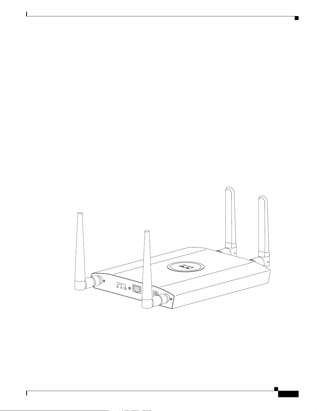
Figure 1-1 shows the access point with antennas.
Hardware Features
Figure 1-1 Access Point with Antennas
STATUS
ETHERNET
RADIO
MODE
CONSOLE
ETHERNET
48VDC
2.4 GHz RIGHT / PRIMARY
2.4 GHz LEFT
135434
OL-8371-05
Cisco Aironet 1240AG Series Access Point Hardware Installation Guide
1-3
Page 18
Hardware Features
Chapter 1 Overview
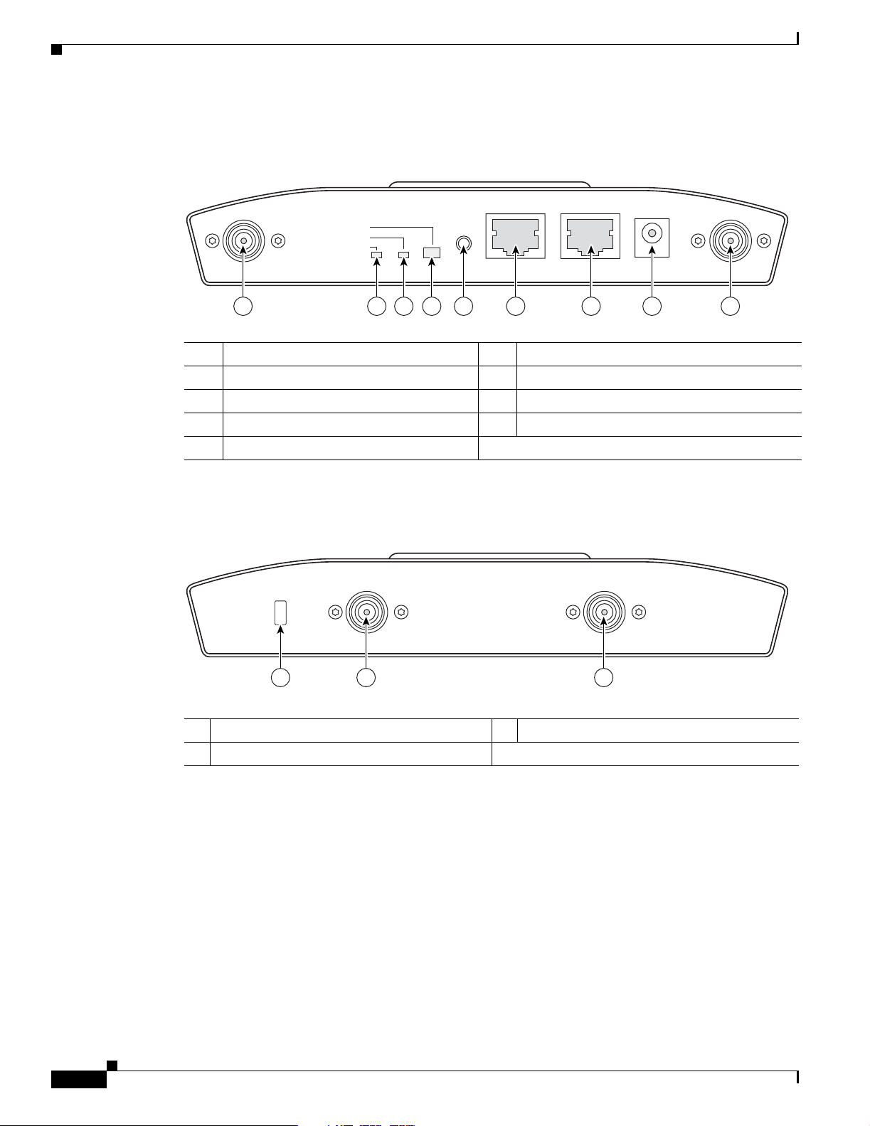
Figure 1-2 illustrates the 2.4-GHz connector end of the access point.
Figure 1-2 Access Point 2.4 GHz Connector End
2.4 GHz LEFT
STATUS
RADIO
ETHERNET
CONSOLE
MODE
ETHERNET
48VDC
2.4 GHz RIGHT/PRIMARY
6 7 8 91 5432
1 2.4-GHz antenna connector (left) 6 Console port (RJ-45)
2 Ethern et LED 7 Ethernet port (RJ-45)
3 Radio LED 8 48-VDC power port
4 Status LED 9 2.4-GHz antenna connector (right/primary)
5 Mode button
Figure 1-3 illustrates the 5-GHz connector end of the access point.
Figure 1-3 Access Point 5-GHz Connector End
5 GHz ANTENNA w/RP-TNC
135435
LEFT
1
RIGHT / PRIMARY
23
1 5-GHz antenna connector (left) 3 Security key slot
2 5-GHz antenna connector (right/primary)
135436
1-4
Cisco Aironet 1240AG Series Access Point Hardware Installation Guide
OL-8371-05
Page 19

Chapter 1 Overview
Single or Dual-Radio Operation
The 1242AG access poin t sup por ts si mul tane ou s r adio o pera tio n us ing a 2.4-G Hz 80 2.1 1g ra dio an d a
5-GHz 802.11a radio. The 1242G access point supports a single 2.4-GHz 802.11g radio. Each radio uses
dual-diversity integrated antennas.
The 5-GHz rad io i ncor por ate s a n U nli cense d Nati onal I nform at ion I nfrast r uctu re ( UNI I) radi o
transceiver operating in the UNII 5-G Hz freq uency bands. Th e 802.1 1g radio is called Radio0 and the
802.11a radio is called Ra dio1 .
Antennas Supported
Table 1-1 l ist s th e s uppo rte d ac cess point ant ennas.
Table 1-1 Supported Antennas
Hardware Features
Ethernet Port
Gain
2.4-GHz Antennas
Diversity ceiling omnidirectional 2 Articulated omnidirectional 3.5
Articulated dipole 2.2 Diversity omnidirectional 4.5
Ceiling omnidirectio nal 5.2 Omnidirectional 6
Wall patch directional 6 Diversity patch directional 7
Mast mount omni dire ctio na l 5.2 Patch directional 9.5
Diversity pillar omnidirectiona l 5.2
Diversity patch directional 6.5
Patch directional 9
Yagi directional 10
The auto-sensing Ethernet port (see Figure 1-2) accepts an RJ-45 connector, linking the access point to
your 10BASE-T or 100BASE-T Ethernet LAN. The access point can receive power through the Ethernet
cable from a power injector, switch, or power patch pane l. Th e Eth ern et MAC address is print ed on th e
label on the back of the access point (refer to the “Locating the Produc t Se ria l Num ber” sec tion o n
page xiii).
(dBi) 5-GHz Antennas
Gain
(dBi)
Console Port
Note After completin g y our c onfigura tio n cha ng es, y ou mu st re move the seri al cabl e f rom th e acc ess po in t.
OL-8371-05
The serial console po rt can be us ed to moni tor the ac cess poin t power-up sequence s using a ter minal
emulator program. The port is located on the end of the unit (see Figure 1-2). Use an RJ-45 to DB-9 serial
cable to connec t yo ur c omput er’s COM port to t he ac cess po int ’s serial console port . (Ref e r to
Appendix E, “Conso le Cable Pinout s,” fo r a descriptio n of the console por t pinouts.) Assign the
following port settings to a terminal emulator to open the management system pages: 9600 baud, 8 data
bits, No parity, 1 stop bit, a nd no fl ow cont rol.
Cisco Aironet 1240AG Series Access Point Hardware Installation Guide
1-5
Page 20

Hardware Features
LEDs
Power Sources
Chapter 1 Overview
The access point has three LEDs to indicat e Ethernet acti vity, radio activity , and statu s indications (refe r
to the “Checking the Ligh tweight Access Point LEDs” se ction on page 3-2 or the “Checking the
Lightweight Access Point LEDs” section on page 4-3 for additional information). Figure 1-2 shows the
location of the LEDs.
• The Status LED provid es gene ra l op er ating st atu s a nd err or indic ati on s.
• The Ethernet LED sign als Ethern et tra ffic on the wired Ethern et LAN and pr ovides Ethe rnet error
indications.
• The Radio LED signals that wireless packets are being transmitted or received over the radio
interface and provides radio e rror indi cations.
The access point can receive power from an external power module or from inline power using the
Ethernet cable. The access point supports the IEEE 802.3af inline power standard and Cisco CDP Power
Negotiation. Using inline power, you do not need to run a power cord to th e access point because power
is supplied over the Ethernet cable.
Warning
Caution Be careful when handling the access po int; the botto m plate might be ho t.
This product must be connected to a Power over Ethernet (PoE) IEEE 802.3af compliant power source
or an IEC60950 compliant limited power source.
Statement 353
The access poin t sup por ts t he f ol lowing power source s:
• Power module
• Inline power:
–
Cisco Aironet Power Injector (AIR-PWRINJ3 or AIR-PWRINJ-FIB)
–
An inline power capable swi tch, s uch a s th e Cisc o C ataly st 35 50 PWR X L, 3 560- 48PS,
3570-48PS, 4500 with 802.3A F PoE module, or the 650 0 with 802.3A F PoE module
–
Other inline power swi tc hes sup port ing th e IE EE 8 02.3a f inlin e power stan da rd
Note Some switches and patch pan els m ight not provide eno ugh power to ope rate t he a cce ss point w it h bot h
2.4-GHz and 5-GHz radios. At power-up, if the access point is unable to determine that the power source
can supply sufficient power, the access point automatically deactivates both radios to prevent an
over-current condition. The access poi nt also activates a Status LED low power error indicat ion and
creates an error log entry (refer to the “Checking the Lightweight Access Point LEDs” sec tion on
page 3-2 and the “Checking Basic Settings” section on page 3-3).
1-6
Cisco Aironet 1240AG Series Access Point Hardware Installation Guide
OL-8371-05
Page 21
Chapter 1 Overview
UL 2043 Certification
The access point has ad equate fire resistance and low smoke-produci ng charac teri stics suitab le for
operation in a building's environmental air space, such as above suspended ceilings, in accordance with
Section 300-22(c) of the NEC, and with Sec tions 2- 128, 12-0 10(3) and 12- 100 of the Canadian
Electrical Code, Part 1, C 22. 1.
Caution Only the fiber-optic power injector (AIR-PWRINJ-FIB) has been tested to UL 2043 fo r operat ion in a
building’s environmental air space; the AIR- PWRINJ 3 power inj ect or a nd the p ower modu le ar e not
tested to UL 2043 and should not be placed in a building’s environmental air space, such as above
suspended ceilings.
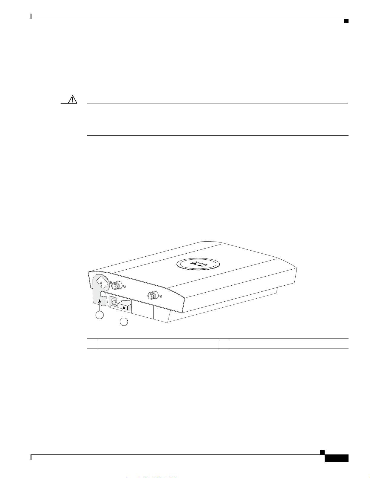
Anti-Theft Features
There are three methods of securing the access point:
• Security cable keyhole—You can use the security cable slot (see Figure 1-3) to secure the access
• Security hasp—When you mount the access point on a wall or ceiling using the mounting plate and
Hardware Features
point using a standard securi ty cable , like those use d on laptop computers (r efer to the “Using a
Security Cable” section on page 2-17).
the security hasp, you can lock the access point to the plate with a padlock (see Figure 1-4).
Compatible padlocks ar e Master Loc k models 12 0T and 121 T or equivalent.
Figure 1-4 Access Point with Security Hasp and Padlock
2.4 GHz LEFT
2.4 GHz RIGHT / PRIMARY
1
2
1 Security hasp 2 Security padlock
135442
OL-8371-05
Cisco Aironet 1240AG Series Access Point Hardware Installation Guide
1-7
Page 22
Network Examples with Autonomous Access Points
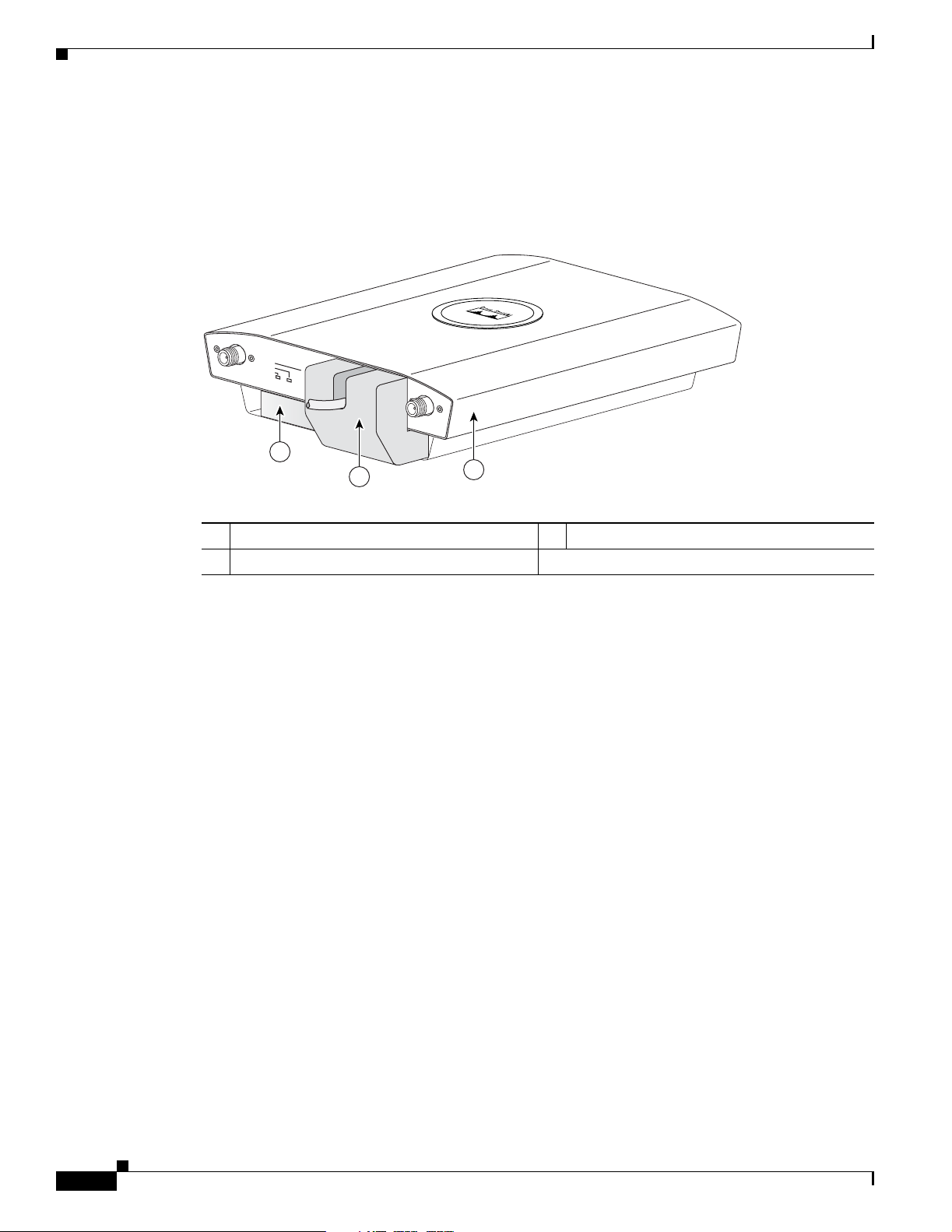
• Cable security bracket—The cable security bracket (see Figure 1-5) attaches to the mounting plate
and covers the consol e port , Et hern et por t, p ower p ort, and t he m ode button to prevent the
installation or removal of the cables or the act i vation of the mode butto n. The cable secur ity bra cket
is user removable pr ior to at tac hin g the m oun tin g p lat e t o a c eil ing or wall .
Figure 1-5 Access Point with Mounting Plate and Cable Security Bracket
Chapter 1 Overview
STATUS
2.4 GHz LEFT
RADIO
ETHERNET
ETHERNET
48VDC
2.4 GHz RIGHT / PRIMARY
1
2
3
1 Mounting plate 3 Access point
2 Cable security bracket
Network Examples with Autonomous Access Points
This section describes the autono mous a ccess p oint’s role in three common wireless network
configurations. The au tonomous a ccess point ’s default configuration is as a root unit co nnec ted to a
wired LAN or as the central unit in an all-wireless network.
The autonomous 1240AG series access point supports th ese opera ting wir eless modes:
• Root access point—Connected to a wired LAN and supports wireless clients.
• Repeater access point—Not connected to a wired LAN, associates to a root access point, and
supports wireless clients
• Workgroup bridge—Not connected to a wired LAN, associates to a root access point or bridge, and
supports wired network devices.
135496
1-8
• Root bridge—Conne cted t o a w ired LA N a nd sup por ts no n-r oo t br idge s and wi reless cli ent s.
• Non-root bridge — Not co nne cte d t o a wir ed LAN, a ssoci ates to a r oot bri dg e, su ppo rts w ire les s
clients, and supports wired clients.
Cisco Aironet 1240AG Series Access Point Hardware Installation Guide
OL-8371-05
Page 23
Chapter 1 Overview
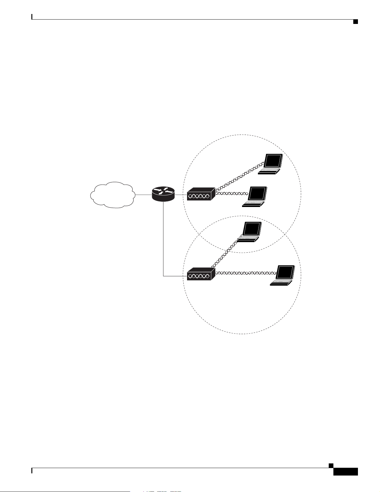
Root Access Point on a Wired LAN
An autonomous access point connected directly to a wired LAN provides a connection point for wireless
users. If more th an o ne auto nomo us acce ss point i s conn ected to th e LAN, user s can r oam fro m one a rea
of a facility to another without losing their connect ion to the netw ork. As users mov e out of range of one
access point, they automatically connect to the network (associate) through another access point. The
roaming process is seamless and transparent to the user. Figure 1-6 shows access points acting as root
units on a wired LAN.
Figure 1-6 Access Points as Root Units on a Wired LAN
Network Examples with Autonomous Access Points
Access point
Access point
135445
OL-8371-05
Cisco Aironet 1240AG Series Access Point Hardware Installation Guide
1-9
Page 24
Network Examples with Autonomous Access Points
Repeater Unit that Extends Wireless Range
An autonomous access po int can be co nfigured as a stand- alone re peater to extend the ran ge of your
infrastructure o r to ove rcome an obstac le that bloc ks radio com munication. The repeater fo rwards tr aff ic
between wireless users and th e wir ed LAN by sending packets to either anoth er re peater or to an access
point connected to the wired LAN. The data is sent through the route that provides the best performance
for the client. Figu re 1- 7 shows an autonomous access point acting as a repeater. Consult the Cisco IOS
Software Configuration Guide for Cisco Aironet Access Points for instructions on set ting up an ac cess
point as a repeater.
Note Non-Cisco client devices might have difficulty comm unic ating wi th r epea ter ac cess points.
Figure 1-7 Access Point as Repeater
Chapter 1 Overview
Access point Repeater
135444
1-10
Cisco Aironet 1240AG Series Access Point Hardware Installation Guide
OL-8371-05
Page 25
Chapter 1 Overview
1
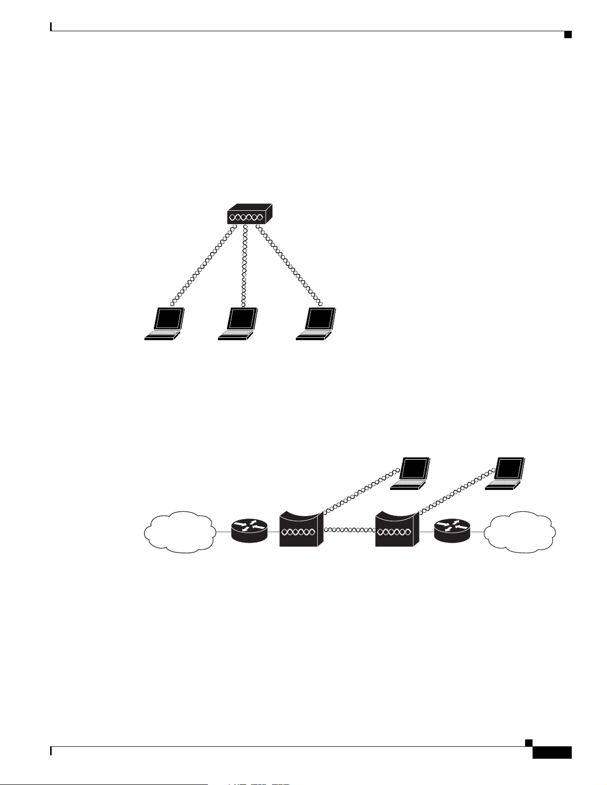
Central Unit in an All-Wireless Network
In an all-wireless network, an autonomous access point acts as a stand-alone root unit. The autonomous
access point is not attached to a wired LAN; it functions as a hub linking all stations together . The acce ss
point serves as the focal point for comm unication s, incr easing the commu nicat ion range of w ireless
users. Figure 1-8 shows an autonomous access point in an all-wireless network.
Figure 1-8 Access Point as Central Unit in All-Wireless Network
Access point
Network Examples with Autonomous Access Points
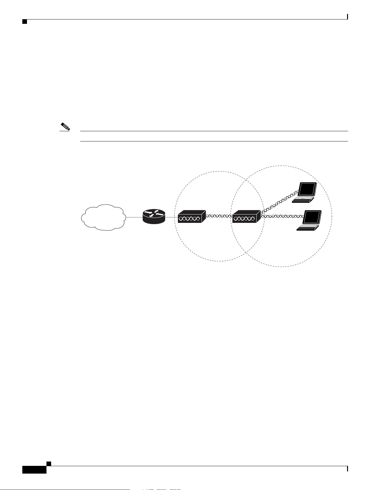
Bridge Network with Wireless Clients
The access po int sup por ts root b ridg e and non- ro ot b ridge role s u sed to int erco nne ct a re m ote LAN to
the main LAN (see Figure 1-9). The bridge units can also support wireless clients.
Figure 1-9 Root Bridge and Non-root Bridge with Clients
Root bridge Non-root bridge
35443
135446
OL-8371-05
Cisco Aironet 1240AG Series Access Point Hardware Installation Guide
1-11
Page 26
Network Examples with Autonomous Access Points
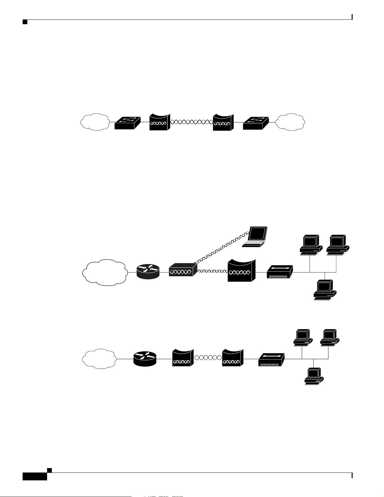
Point-to-Point Bridge Configuration
In a point-to-point bri dge configur ation , two bri dges int erco nnec t two L AN net works u sing a wi reless
communication l ink (see Figu re 1-10). The bridge connect ed to the mai n LAN ne twork is classified as
a root bridge and the othe r bridge is cl assified as a non -root bri dge.
Figure 1-10 Point-to-Point Bridge Configuration
Chapter 1 Overview
Workgroup Bridge Network
The access point su ppo rts a work grou p br idge r ole to i nte rconn ec t re mot e Et hern et workst at ions to t he
main LAN. The workgroup br idge can commun icate w ith an access poi nt (see Figure 1-11) or with a
bridge (see Figu re 1 -12 ).
Figure 1-11 Workgroup Bridge Communicating with an Access Point
Root bridge Non-root bridge
Access point
Workgroup bridge
117029
135448
1-12
Figure 1-12 Workgroup Bridge Communicating with a Bridge
Bridge Workgroup
Cisco Aironet 1240AG Series Access Point Hardware Installation Guide
bridge
135499
OL-8371-05
Page 27
Chapter 1 Overview
1
Network Example with Lightweight Access Points
Network Example with Lightweight Access Points
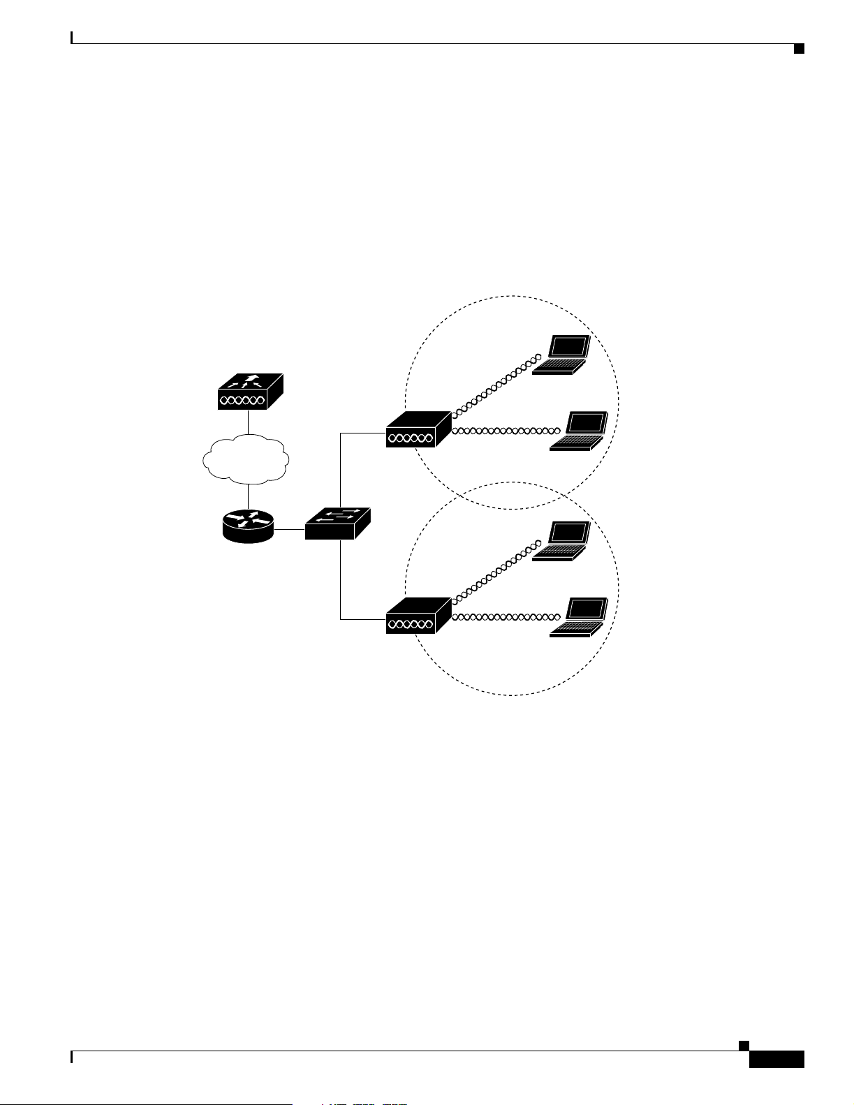
The lightweight access points support Layer 3 network operation. Lightweight access points and
controllers in L aye r 3 c on figuratio ns use I P a ddr esses an d UD P p acket s, w hic h ca n be ro ut ed t hr ough
large networks. Layer 3 o pera tio n is sca la ble an d re co mm ended by Ci sco.
This section illustrates a typical wireless network configuration containing lig htweight access points and
a Cisco Wireless LAN Controlle r (se e Fi gure 1-13).
Figure 1-13 Typical Lightweight Access Point Network Configuration Example
LWAPP
LWAPP
58085
OL-8371-05
Cisco Aironet 1240AG Series Access Point Hardware Installation Guide
1-13
Page 28

Network Example with Lightweight Access Points
Chapter 1 Overview
1-14
Cisco Aironet 1240AG Series Access Point Hardware Installation Guide
OL-8371-05
Page 29

CHA PTER
2
Installing the Access Point
This chapter describes the installation of the access point and includes these sections:
• Safety Informat ion, p age 2-2
• Warnings, page 2-2
• Unpacking the Access Po int, page 2-3
• Basic Installation Guidelines, page 2-4
• Controller Discovery Process for Lightweight Access Points , page 2- 4
• Mounting Overview, page 2-7
• Mounting on a Horizontal or Vertical Surface, page 2-9
• Mounting Below a Suspended Ceiling, page 2 -10
• Mounting Above a Suspended Ceiling, page 2-11
• Mounting Access Poi nt o n a Deskt op or Shel f, pa ge 2-14
• Cable Security B ra cket, page 2-14
• Attaching the Access Point to the Mounting Plate, page 2-16
• Securing the Access Point, page 2-17
• Connecting the Ethernet and Power Cables, page 2-20
• Powering Up the Access Point, page 2-22
OL-8371-05
Cisco Aironet 1240AG Series Access Point Hardware Installation Guide
2-1
Page 30

Safety Information
Safety Information
Follow the guidelines in this section to ensure proper operation and safe use of the access point.
FCC Safety Compliance Statement
The FCC with its action in ET Do cket 96-8 has adop ted a safe ty standar d for human exposur e to radio
frequency (RF) electromagnetic energy emitted by FCC certified equipment. When used with approved
Cisco Aironet antennas, Ci sco Airo net product s meet th e uncont rolled environmental limits fou nd in
OET-65 and ANSI C95.1, 1991 . Proper installat ion of this ra dio acc ording to the instruc tions fou nd in
this manual will result in user exposure that is substantially below the FCC recommended limits.
General Safety Guidelines
Do not hold any c om ponent co ntain in g a radi o so th at th e an ten na is ver y c lose t o or t ou chin g a ny
exposed parts of the body, especially the face or eyes, while transmitting.
Chapter 2 Installing the Access Point
Warnings
Warning
Warning
Warning
Warning
Translated versions of the following safety warnings are provided in Appendix A, “Translated Safe ty
Warnings.”
This warning symbol means danger. You are in a situation that could cause bodily injury. Before you
work on any equipment, be aware of the hazards involved with electrical circuitry and be familiar
with standard practices for preventing accidents. Use the statement number provided at the end of
each warning to locate its translation in the translated safety warnings that accompanied this device.
Statement 1071
SAVE THESE INSTRUCTIONS
Read the installation instructions before you connect the system to its power source.
This product must be connected to a power-over-ethernet (PoE) IEEE 802.3af compliant power source or an
IEC60950 compliant limited power source.
This product relies on the building’s installation for short-circuit (overcurrent) protection. Ensure that
the protective device is rated not greater than: 20A
Statement 353
Statement 1005
Statement 1004
2-2
Warning
Cisco Aironet 1240AG Series Access Point Hardware Installation Guide
Do not operate your wireless network device near unshielded blasting caps or in an explosive
environment unless the device has been modified to be especially qualified for such use.
Statement 245B
OL-8371-05
Page 31

Chapter 2 Installing the Access Point
Unpacking the Access Point
Warning
In order to comply with FCC radio frequency (RF) exposure limits, antennas should be located at a
minimum of 7.9 inches (20 cm) or more from the body of all persons.
Unpacking the Access Point
Follow these steps to unpack the access point:
Step 1 Open the shipping container and carefully remove the contents.
Step 2 Return all pack i ng ma ter ials to the sh ipping c onta iner a nd save it.
Step 3 Ensure that all items listed in the “Package Contents” section are included in the shipment. Check each
item for damage. If any item is damage d or missin g, notif y your autho rized Cisc o sales repre sentat ive.
Package Contents
Each access point pack age co ntain s the foll owing items:
• Cisco Aironet 1240AG Series A ccess Po int or C isco Airon et 1 240 AG Series Ligh twei ght Access
Point
• Cisco Aironet 1240AG Series Power Mo dule ( universal power modul e)– opti onal
• Mounting hardware kit
Statement 332
–
One mounting plate with cable security bracket
–
Two suspended ceiling T-rail clips, spacers (accommodates standard and recessed T-rails), and
nuts.
–
One security hasp
–
Two 6 x 32 x 1/2 in. pan head Phillips machine screws
–
Four 8 x 18 x 3/4 in. pan head Phillips sheet metal screws
–
Four #8 plastic wall anch ors
–
One 10 x 24 nu t (f or gr oun d s tud on mou nt ing brac ket)
–
Four rubber foot p ads
–
Two cable tie wraps
• Product quick start gui de
• Product translated safety warnings document
• Cisco product registration an d Cisco docum entati on feedbac k card s
OL-8371-05
Cisco Aironet 1240AG Series Access Point Hardware Installation Guide
2-3
Page 32

Basic Installation Guidelines
Basic Installation Guidelines
Because the ac cess po int i s a ra dio d evice, i t is susce pti ble to i nter fere nce tha t c an red uc e t hro ughput
and range. Follow these basic guidelines to ensure the best possible performance:
• Ensure that a site survey has been performed to determine the optimum placement of access points.
• For lightweight access po ints , chec k the lat est rel ease note s to ensure th at you r co ntro ller sof t ware
version supports the access points to be installed. You can find the controller release notes by
selecting your contr oller un der Wireless LAN Controllers at this URL:
http://www.cisco.com/en/US/products/hw/wireless/tsd_produ cts_supp ort_cat egory_home.html
• Ensure that access points are not mounted closer than 20 cm (7.9 in) from
• Do not mount the access point within 3 feet of metal obs tructions.
• Install the access point away from microwave ovens. Microwave ovens operate on the same
frequency as the access point and can cause signal interference.
• Do not mount the ac cess point out side o f buildings.
• Do not mount the a cce ss poi nts on building peri meter wall s un less outside coverage i s desi red.
Chapter 2 Installing the Access Point
the body of all persons
.
Controller Discovery Process for Lightweight Access Points
The lightweight access point supports these controller discovery processes:
• DHCP server discovery—Uses DHCP Option 43 to provide controller IP addresses to the access
points. Cisco switches support a DHCP server option. For additional information, refer to the
“Configuring DHCP Option 43 fo r Lightwe ight Acces s Points” sec tion on page G-1.
• DNS server discovery—The access poi nt uses the name CISCO-LWAPP-CONTROLLER.<local
domain> to discover the cont roll er IP addr ess es from a DN S ser ver. Where <local domain> is the
access point doma in n am e.
• Locally stored contr oller IP add resses—If the ac cess point was pre viousl y associated to a controller ,
the IP addresses of the primary, secondary, and tertiary controllers are stored in the access point
non-volatile memory. The process of storing controller IP addresses in access points for later
deployment is cal led pri ming the a cce ss poi nt. For a ddit iona l in for ma tion, re fer t o th e “P r iming
Lightweight Access Points Prior to Deployment” sec tion on page F-1.
Yo u can also ma nuall y configure co ntrolle r informa tion usin g CLI comm ands on new
(out-of-the-bo x) access points that are not connected to a cont roller . For ad ditional inform ation refer
to the “Manually Configuring Con troll er I nfo rmat ion Usi ng the A cce ss Po int CL I” s ectio n on
page 4-7.
Cisco recommends that you configure a DHC P server with Option 43 to provide t he contr oller IP
addresses to your access points. Cisco switches provide a DHCP server option that is typically used for
this purpose.
2-4
Cisco Aironet 1240AG Series Access Point Hardware Installation Guide
OL-8371-05
Page 33

Chapter 2 Installing the Access Point
Deploying the Access Points on the Wireless Network
Deploying the Access Points on the Wireless Network
Prior to beginning t he a ct ual acc ess po int de ployme nt, p erfor m thes e tasks :
• Ensure that a site survey has been preformed.
• Ensure that your network i nfrastr ucture devices are opera tional an d prope rly configured.
• For lightweight access points, perform these tasks:
–
Ensure that your cont rollers ar e connec ted to swit ch trunk ports.
–
Ensure that your switch is co nfigured wit h untagge d access por ts for co nnectin g your acce ss
points.
–
Ensure that a DHCP server with Option 43 configured is reac hable by your acc ess points .
To deploy your access points, follow these steps:
Step 1 Obtain the access point location map created during your building site survey.
Step 2 Review the access point locations and identify the specific mounting methods required for each access
point location.
Step 3 For each access point perform these steps:
a. For lightweight access points, record the access point MAC address on the access point location
map. When you hav e completed the acce ss point deployment, r eturn the access point MA C addre sses
and the access po int loc ation s o n t h e ac c ess po in t loc ati on map s or f loor pla ns to y our net work
planner or manage r. The network op er ator s ca n use t he M AC address a nd l ocati on inf orm ati on to
create maps for precise wireless system management.
b. At tach your acce ss point to the mounting pla te (see the “Attaching the Access Point to the Mounting
Plate” section on page 2 -16).
c. Mount the access point at the in dicat ed d estina ti on usi ng the sp ec ified mo unti ng me tho d. For
specific mounting instructions, see these sections:
–
Horizontal or vertical surface, such as a ceiling or wall (see the “Mounting on a Horizontal or
Vertical Surface” section on page 2-9).
–
Below a suspended ceiling (see the “Mounting Below a Suspended Ceiling” sect ion on
page 2-10).
–
Above a suspended ceiling (see the “Mounting Above a Suspended Ceiling” section on
page 2-11).
–
On a desktop or shelf (see the “Mounting Access Point on a Desktop or Shelf” section on
page 2-14.
d. Optionally secure the access point using a padlock or security cable (see the “Securing the Access
Point” section on page 2-17).
e. Connect the access point cables (Ethernet, optional power, optional antennas). For instructions see
the “Connecting the Ethe rnet and Power Cab les” sec tion o n page 2-20.
OL-8371-05
f. On power up, verify that the access point is associated to a controller and operating normally. For
additional information, refer to the “Checking the Lightweight Access Point LEDs” se ction on
page 3-2 or the “Checking t he L ightw eig ht Ac ce ss Poi nt L EDs” sec tion on page 4-3.
Cisco Aironet 1240AG Series Access Point Hardware Installation Guide
2-5
Page 34

Deploying the Access Points on the Wireless Network
Step 4 For lightweight access points, after your access points are deployed, ensure that your controller is not
configured as a master controller. A master controller should only be used for configuring access points
and not in a wo rking net work.
Access Point Layout and Connectors
Figure 2-1 illustrates the 2.4-GHz connector end of the access point.
Figure 2-1 Access Point 2.4-GHz Connector End
Chapter 2 Installing the Access Point
2.4 GHz LEFT
STATUS
RADIO
ETHERNET
CONSOLE
MODE
ETHERNET
48VDC
2.4 GHz RIGHT/PRIMARY
6 7 8 91 5432
1 2.4-GHz antenna connector (left) 6 Console port (RJ-45)
2 Ethern et LED 7 Ethernet port (RJ-45)
3 Radio LED 8 48-VDC power port
4 Status LED 9 2.4-GHz antenna connector (right/primary)
5 MODE button
Figure 2-2 illustrates the 5-GHz connector end of the access point.
Figure 2-2 Access Point 5-GHz Connector End
135435
2-6
5 GHz ANTENNA w/RP-TNC
LEFT
1
1 5-GHz antenna connector (left) 3 Security key slot )
2 5-GHz antenna connector (right/primary
Cisco Aironet 1240AG Series Access Point Hardware Installation Guide
RIGHT / PRIMARY
135436
23
OL-8371-05
Page 35

Chapter 2 Installing the Access Point
Mounting Overview
Yo u can mou nt the acc ess point on any of the fo llowing surface s:
• Horizontal or vertical flat surfaces, such as walls or ceilings
• Suspended ceilings (above and below)
Caution The access point, the antennas, and the power source (power injector or power module) are not designed
for outdoor use and mu st be loca ted in a n ind oor environment.
The access point ships with a detachable mounting plate and the necessary mounting hardware. Because
it is detachable, you can use the mounting plate as a template to mark the positions of the mounting holes
for your installation. You then install the mounting plate and attach the access point when you are ready.
Refer to Figure 2-3 to locate the various mounting holes for the method you intend to use.
Figure 2-3 Mounting Plate
Mounting Overview
OL-8371-05
1 Key hole clips 4 Ceiling or wall mounting holes
2 Cable access openings 5 Ground connection
3 Locking detent 6 Cable tie point
Caution Only the fiber-op tic power injector (AIR-PWRINJ-FIB) has been tested to UL 2043 for operation in a
buil di ng’s env iro nm ent al air spa ce ; n o ot he r p ow er inj ect or s o r po wer modules have been tested to UL 2043
and they sh ould not be plac ed in a building’s en vi ronme ntal air s pac e, su ch as abo v e susp ended ceilin gs.
Cisco Aironet 1240AG Series Access Point Hardware Installation Guide
2-7
Page 36

Mounting Overview
Note The access point pro vides adequa te f ir e res istan ce and lo w smok e- produ cing ch aracte rist ics s uitable fo r
Note When mounting the access point in a building’s environmental air space, you must use Ethernet cable
Chapter 2 Installing the Access Point
operation in a building's environmental air space (such as above suspended ceilings) in accordance with
Section 300-22(C) of the National Electrical Code (NEC).
suitable for operation in environmental air space in accordance with Section 300-22(C) of the National
Electrical Code (NEC).
A mounting hardware kit is provided that contains the hardware and fasteners necessary to mount the
access point. Refer to the Table 2-1 to identify the materials you need to mount your access point, then
go to the section containi ng the spec ific mounting proc edur e.
Table 2-1 Material Needed to Mount Access Point
Mounting Method Materials Required In Kit
Horizontal or vertical surface Four #8 x 1 in. (25.4 mm) screws
Four wall anchors
3/16 in. (4.7 mm) or 3/32 in. (2.3 mm) dr ill bit
Drill
Standard screwdriver
Suspended ceiling Two T-rail clips with studs
Two plastic spacers
Two 1/4–20 Keps nuts with built-in washers
Standard screwdriver, wrench, or pliers
Yes
Yes
No
No
No
Yes
Yes
Yes
No
2-8
Cisco Aironet 1240AG Series Access Point Hardware Installation Guide
OL-8371-05
Page 37

Chapter 2 Installing the Access Point
Mounting on a Horizontal or Vertical Surface
Mounting on a Horizontal or Vertical Surface
Follow these steps to mount the access point on a horizontal or vertical surface.
Step 1 Use the mounting plate as a template to mark the locations of the four mounting holes.
Note When mounting on a vertical surface, position the cable security bracket on the bottom.
Step 2 Drill one of the following sized holes at the locations you marked:
• 3/16 in. (4.7 m m) if you are u sing wall anc ho rs
• 1/8 in. (6.3 mm) if you are no t using wall anchor s
Step 3 Install the anchors into the wall if you are using them. Otherwise, go to Step 4.
Step 4 Secure the mounting plate to the surface using the #8 fasteners.
Note On a vertical surface, mount the plate with the security hasp slot on the top.
Step 5 Attach the access poin t to the mo unting pla te.
Note For a more secure installation you should attach the mounting plate to a stud or major structural
member and use the appropriate fasteners.
OL-8371-05
Cisco Aironet 1240AG Series Access Point Hardware Installation Guide
2-9
Page 38

Mounting Below a Suspended Ceiling
Mounting Below a Suspended Ceiling
Note To comply with NEC c ode , a #1 0-24 gro und ing lu g is pr ovided o n the mo unti ng pla te.
Yo u should review Figure 2-4 be fore beginning the mounting pro cess.
Figure 2-4 T-Rail Mounting Parts
Chapter 2 Installing the Access Point
2-10
1 Suspended ceiling T-rail 4 mounting plate
2 T-rail clips 5 Keps nut (contains an attached lock washer)
Plastic spacer (used with recessed ceiling
3
tiles)
Cisco Aironet 1240AG Series Access Point Hardware Installation Guide
OL-8371-05
Page 39

Chapter 2 Installing the Access Point
Follow these steps to mount your access point on a suspende d ceilin g:
Step 1 Decide where you wan t to mo unt th e acc ess po in t.
Step 2 Attach two T-rail clips to the suspended ceiling T-rail.
Step 3 Use the mounting plate to adjust the distance between the T-rail clips so that they align with the holes in
the mounting plate.
Step 4 Use a standard screwdriver to tighten the T-rail clip studs in place on the suspended ceiling T-rail. Do
not overtighten.
Step 5 If using recessed ceiling tiles, install a plastic spacer on each T-rail clip stud. The spacer’s legs should
contact the suspended ceiling T-rail.
Step 6 Attach the mounting plate to the T-rail clip studs and start a Keps nut on each stud.
Step 7 Use a wrench or plier s to tighte n the Keps nuts. Do no t overtighten.
Step 8 To attach the access point to the mounting plate, see the “Attaching the Access Point to the Mounting
Plate” section on page 2 -16.
Step 9 If you need additional security, refer to the “Securing the Access Point” section on page 2-17 for
additional information.
Mounting Above a Suspended Ceiling
Step 10 Verify the access point is operating (see the “Powering Up the Access Point” section on page 2-22).
Mounting Above a Suspended Ceiling
The access point mounting plate is designed to be integrated into the T-bar grid above the tiles of a
suspended ceiling. Using a T-bar box hanger and bracket mounting clip (not supplied) such as the
Erico 512A and BHC, you orient the access point antenna just above the top surface of a standard ceiling
tile. You may need to modify a thicker tile to allow room for the antenna.
OL-8371-05
Cisco Aironet 1240AG Series Access Point Hardware Installation Guide
2-11
Page 40

Mounting Above a Suspended Ceiling
It may be helpful to refer to Figure 2- 5 befor e proceedi ng.
Figure 2-5 Above Suspended Ceiling Parts
3
2
1
Chapter 2 Installing the Access Point
4
5
ARY
Hz RIGHT / PRIM
2.4 G
C
D
V
8
4
T
E
N
R
E
H
T
E
E
L
O
S
N
O
C
Hz LEFT
E
D
2.4 G
O
M
ETHERNET
IO
RAD
TATUS
S
3
2
1
135583
1
Suspended ceiling T-rail
2
T-rail clip
3
Height adjustment screw
4
T-bar box hanger
5
Bracket mounting clip
Caution Only the fiber-optic power injector (AIR-PWRINJ-FIB) has been tested to UL 2043 for operation in a
buil din g’ s en vir onm enta l air spac e; n o ot her p ow er in jec tors or po wer modules have been tested to UL 2043
and they sh ould not be plac ed in a building’s en vi ronme ntal air s pac e, su ch as abo v e susp ended ceilin gs.
2-12
Cisco Aironet 1240AG Series Access Point Hardware Installation Guide
OL-8371-05
Page 41

Chapter 2 Installing the Access Point
The bracket moun tin g c l ip r e quire s th e use o f two m oun tin g c li p h ol es on t he mo u ntin g plat e ( see
Figure 2-6).
Figure 2-6 Mounting Plate Holes
Mounting Above a Suspended Ceiling
1 Bracket mounting clip holes
Follow these steps to mount the access point above a suspended ceiling.
Step 1 Insert the bracket mounting clip’s tab into the large hole on the access point mounting plate.
Step 2 Place the clip over the T -bar box hanger and secure it to the access point mounting plate (see Figure 2-7)
with the 1/4-20 fas tene r (su ppl ie d wi th the T-bar hanger).
Figure 2-7 Access Point Mounting Plate
OL-8371-05
135498
Note The illustration shows the access point mounting plate mounted perpendicular to the T-bar box
hanger. You can also mount the brac ket parall el to the T-bar box hanger.
Cisco Aironet 1240AG Series Access Point Hardware Installation Guide
2-13
Page 42

Mounting Access Point on a Desktop or Shelf
Step 3 Determine the location in the ceiling where you will mount the access point and remove an adjacent
ceiling tile.
Step 4 Orient the access po int 2 -GHz and 5-GH z ante nnas so that the y ar e po inting do wn when m ounted on th e
T-bar Box hanger.
Step 5 Adjust the height of th e T-bar box hanger to provide antenna clear ance ab ove the ceiling tile usi ng the
height adjusting scr ews (refer to Figure 2-5).
Step 6 Attach the T-rail clips on each end of the T-bar box hanger to the ceiling grid T-rails. Make sure the clips
are securely attached to the T-rails.
Step 7 Connect a drop wir e to a building struc tural elem ent and th rough the hole provided in the bracket
mounting clip. This additional support is required in order to comply with the U.S. National Electrical
Safety Code.
Step 8 To attach the access point to the mounting plate, see the “Attaching the Access Point to the Mounting
Plate” section on page 2 -16.
Step 9 If you need additional security, see the “Securing the Access Point” section on page 2-17 for additional
information.
Step 10 Verify the access point is operating before replacing the ceiling tile (see the “Powering Up the Access
Point” section on page 2-22).
Chapter 2 Installing the Access Point
Mounting Access Point on a Desktop or Shelf
When placing the access point on a desktop of shelf, the use of the mounting plate is optional. The
mounting plate can be u sed to shie ld t he u s er f rom th e hot bott om surfac e of th e a cce ss point wh en
movement of the access point may be necessary. The access point is shipped with four rubber pads that
you can place on the bottom of the access point or the mounting plate to help prevent sliding or
scratching the surfa ce o f your d eskto p or she lf. For i nfo rmat ion on conn ec ti ng t he a cce ss p oint c a bles,
see the “Connecting the Ethernet and Power Cables” section on page 2-20.
Cable Security Bracket
The access point mounting plate has an attached cable security bracket that covers the console port,
Ethernet port, pow er port, an d the mode b utto n to pre v en t the installa tion or remo val of the cables or the
activat ion of the mode b utton. If d esired, the cable secur ity brack et can be remov ed prior t o attachin g the
mounting plate to a ce ilin g o r wall.
2-14
Cisco Aironet 1240AG Series Access Point Hardware Installation Guide
OL-8371-05
Page 43

Chapter 2 Installing the Access Point
Figure 2-8 Access Point with Mounting Plate and Cable Security Bracket
Cable Security Bracket
STATUS
2.4 GHz LEFT
RADIO
ETHERNET
ETHERNET
48VDC
2.4 GHz RIGHT / PRIMARY
1
2
1 Mounting plate 3 Access point
2 Cable security bracket
Removing the Cable Security Bracket
The cable securi ty br acket (s ee Figure 2-9) is designed to help prevent someone from using the Mode
button to reset the access point to default values or from using the serial console cable to access the
access point’s CLI interface or from removing the Ethernet cable. If this security protection is not
considered necessary, you can remove the cable security bracket.
Figure 2-9 Cable Security Bracket Screws
135496
3
OL-8371-05
1 Cable security bracket 3 Mounting plate
2 Cable security bracket screws
Cisco Aironet 1240AG Series Access Point Hardware Installation Guide
2-15
Page 44

Chapter 2 Installing the Access Point
Attaching the Access Point to the Mounting Plate
To remove the cable security bracket from the mounting plate, follow these instructions:
Step 1 Position the mounting plate with the cable security bracket pointing down (see Figure 2-9).
Step 2 Remove the two screws that attach the bracket to the mounting plate using a phillips screw driver.
Attaching the Access Point to the Mounting Plate
Follow these steps to attach the access point to the mounting plate:
Step 1 If your mounting plate has the cable security bracket, follow these steps:
a. Connect the Ethernet cable to the access point Ethernet port (see the “Connecting the Et h ern et a nd
Power Cables” section on page 2-20).
b. If not using on-line power, connect the power module ’s power cable to the ac cess point 48- VDC
connector.
c. Carefully feed the Ethernet and power cables through the cable notch on the cable security bracket
and slide the cables to the r ight o r le ft to sec ure th e cable s (see the “ Cable Secur ity Br acket” sec tion
on page 2-14).
Note If your access point is connected to Ethernet in-line power, do not connect the local power
module to the access point. Using two power sources on the access point might cause the ac cess
point to shut down to protec t int erna l co mp one nts a nd m ight c au se th e sw itch to shut d own the
port to which the a cce ss point is conn ect ed. If your ac cess po int shu t s down, you m ust r emove
all power and reconnect only a single power source.
Step 2 Line up the four keyhole clips on the mounting plate with the large ends of the keyhole-shaped holes on
the access point.
Note The keyhole clips on each side of the mounting plate are offset and can only be positioned in one
direction onto the access point.
Step 3 Insert the mounting plate clips into the keyhole shaped holes on the access point.
Step 4 Slide the access point towards the cable security bracket end of the mounting bracket while exerting
slight pressure to force the acc ess point an d mounti ng plate toge ther. You will hear a slight click when
the locking detents contact the access point and locks it into place.
Step 5 Attach and adjust the antenna(s) or antenna cables to the access point antenna connectors.
2-16
Note The 5-GHz antennas and antenna cables have a blue dot or blue label. Connect only antennas or
antenna cables with blue dots or labels to the access point’s 5-GHz antenna connectors.
Cisco Aironet 1240AG Series Access Point Hardware Installation Guide
OL-8371-05
Page 45

Chapter 2 Installing the Access Point
Step 6 If your mount ing pla te does not have the c able secu ri ty b racke t, f ollow these ste ps:
a. Co nn ec t a CAT 5 Ethernet cable to the acces s po i n t E th ern et port (see the “Connecting the Ethernet
and Power Cables” secti on on pa ge 2-20).
b. If using local power, insert the power module’s power cable into the access point’s 48-VDC power
port.
Note If your access point is connected to in-lin e power , do not connect the po wer module to the access
point. Using two power sources on the access point might cause the ac cess point to shut down
to protect internal components and might cause the switch to shut down the port to which the
access point is con ne cted. If your a ccess p oint s huts down, you must re move all p ower and
reconnect only a si ngl e power sour c e.
Securing the Access Point
Securing the Access Point
There are two ways to secure yo ur access po int:
• Using a security cable
• Securing the access point to the mounting plate
Using a Security Cable
You can secure the access point by installing a standard security cable (such as the Kensington Notebook
MicroSaver, model number 64068) into the access point security cable slot (see Figure 2-2). The security
cable can be used with any of the mounting methods described in this guide.
Follow these steps to install the security cable.
Step 1 Loop the security ca ble arou nd a nearby imm ovable object.
Step 2 Insert the key into the security cable lock.
Step 3 Insert the security cable latch into the security key slot on the access point.
Step 4 Rotate the key right or left to secure the security cable lock to the access point.
Step 5 Remove the key from security cable lock.
OL-8371-05
Cisco Aironet 1240AG Series Access Point Hardware Installation Guide
2-17
Page 46

Securing the Access Point
Securing the Access Point to the Mounting Plate
The security hasp enables you to use a padlock to secure the access point to the mounting plate. Known
compatible padl ocks a re M a ster Lock m ode ls 1 20T o r 121 T.
To install the security hasp, follow these steps:
Step 1 Insert the security hasp’s key pin (see Figure 2-10) into the key slot on the access poin t (s ee Figure 2-2)
and rotate counterc lockwis e towards the mounti ng plate.
Figure 2-10 Security Hasp
2.4 GHz LEFT
1
2.4 GHz RIGHT / PRIMARY
Chapter 2 Installing the Access Point
135491
Step 2
2
3
4
5
6
1 Key pi n 4 Padlock
2 Security hasp 5 5-GHz access point end
3 Mounting plate security slot 6 Mounting plate
Push the security hasp’s padlock flange through the mounting plate’s security slot.
2-18
Cisco Aironet 1240AG Series Access Point Hardware Installation Guide
OL-8371-05
Page 47

Chapter 2 Installing the Access Point
Step 3 Place your padlock (user supplied) th rough the padl ock hole in the security hasp’s padlock flange
(see Figure 2-11).
Figure 2-11 Security Hasp and Padlock
1
1 Security hasp 2 Pad l oc k
Securing the Access Point
135442
2.4 GHz LEFT
2.4 GHz RIGHT / PRIMARY
2
Step 4
Push the padlock i nto th e re cess ed op en ing betw een the a cce ss poi nt an d th e mo unti ng pl at e.
Note When attaching the mounting plate to a vertical surface, place the security cable bracket end of the
mounting plate on the bot tom.
OL-8371-05
Cisco Aironet 1240AG Series Access Point Hardware Installation Guide
2-19
Page 48

Connecting the Ethernet and Power Cables
Connecting the Ethernet and Power Cables
The access point receives power through the Ethernet cable or an external power module. Figure 2-12
shows the power options for the access point.
Figure 2-12 Access Point Power Options
Option 1 Option 2
Switch with
inline power
S
Y
S
T
1
RPS
2
3
4
S
TA
T
5
UT
IL
DUP
LX
6
SP
E
ED
7
8
10Base-T / 100Base-TX
9
MODE
10 11
12
13
14
15
16
17
18
Catalyst 2950
19
S
ERIE
20
S
21
22
100Base-FX
23
24
23
24
Chapter 2 Installing the Access Point
Switch without
inline power
SYST
1
RP
S
2
3
4
STAT
5
UTI
L
D
UP
LX
6
S
PEED
7
8
10Base-T / 100Base-TX
9
MO
DE
10
11
12
13
14
15
16
17
18
Catalyst 2950
19
SERIES
20
21
22
100Base-FX
23
24
23
24
Power injector
TO
AP/
B
NETWORK
T
O
RI
DGE
Power
cord
Universal
power supply
Warning
Access Point
This product must be connected to a Power over Ethernet (PoE) IEEE 802.3af compliant power source
or an IEC60950 compliant limited power source.
Statement 353
Option 3
Caution This product and all int erc onn ecte d eq uip ment m ust be i nsta lled i ndoors w ith in th e s am e buildi ng,
including the associated LAN connections (as defined by Environment A of the IEEE 802.3af standard).
The access po int power op tio ns:
• Option 1—Switches with sufficient inline power:
135476
2-20
–
An inline power capable swi tch, s uch a s th e Cisc o C ataly st 35 50 PWR X L, 3 560- 48PS,
3750-48PS, 4500 with 802.3A F PoE module, or the 650 0 with 802.3A F PoE module
–
Other inline power swi tc hes sup port ing th e IE EE 8 02.3a f inlin e power stan da rd
• Option 2—Switches without sufficient inline power can use the power injector:
–
Cisco Aironet Power Injector (AIR-PWRINJ3 or AIR-PWRINJ-FIB)
• Option 3—Local power using th e power module
Cisco Aironet 1240AG Series Access Point Hardware Installation Guide
OL-8371-05
Page 49

Chapter 2 Installing the Access Point
Connecting the Ethernet and Power Cables
Note Some older switches and patc h panels migh t not provide enou gh power to operate th e acces s point. At
power-up, if the access point is unable to determine that the power source can supply sufficient power,
the access point automatically deactivates both radios to prevent an over-current condition. The access
point Status LED t urn s am ber a nd an er ror log e ntry is c r eat ed (refe r to th e “ Ch eckin g th e L ightw ei ght
Access Point LEDs” section on page 3-2 or the “Checking the Lightweight Access Point LEDs” section
on page 4-3).
Connecting to an Ethernet Network with an Inline Power Source
Caution Be careful when handling the access po int; the botto m plate might be ho t.
Note If your access point is connected to in-line power, do not connect th e power module to the access point.
Using two power sources on the access point might cause the access point to shut down to protect internal
components and might cause the switch to shut down the port to which the access po int is connected. If
your access point shuts down, you must remove all power and reconnect onl y a single power source.
Follow these steps to connect the access point to the Ethernet LAN when you have an inline power
source:
Step 1 Connect a Category 5 Etherne t cable t o the RJ-45 Ethe rnet connec tor label ed Ethernet on the access
point (see Figure 2-13).
Figure 2-13 Ethernet and Power Ports
2.4 GHz LEFT
STATUS
RADIO
ETHERNET
CONSOLE
MODE
ETHERNET
48VDC
2.4 GHz RIGHT/PRIMARY
1 2
1 Ethernet port 2 48 VDC power port
Step 2
Connect the other end of t he Ether net cable to one of the following:
• A switch with inline power (see the “Connecting the Ethernet and Power Cables” section on
page 2-20).
135494
OL-8371-05
• The end of a Cisco Airo net power injec tor l abe led To A P/Bridge. Connect the other end labe led To
Network to your 10/100 Ethern et LAN.
Cisco Aironet 1240AG Series Access Point Hardware Installation Guide
2-21
Page 50

Powering Up the Access Point
Connecting to an Ethernet Network with Local Power
Caution Be careful when handling the access po int; the botto m plate might be ho t.
Note If your access point is connected to in-line power, do not connect th e power module to the access point.
Using two power sources on the access point might cause the access point to shut down to protect internal
components and might cause the switch to shut down the port to which the access po int is connected. If
your access point shuts down, you must remove all power and reconnect onl y a single power source.
Follow these steps to connect the access point to an Ethernet LAN when you are using a local power
source:
Step 1 Connect a Category 5 Etherne t cable t o the RJ-45 Ethe rnet connec tor label ed Ethernet on the access
point (see Figure 2-13).
Step 2 Connect the power module output connector to the access point’s 48-VDC power port (see Figure 2-13).
Chapter 2 Installing the Access Point
Step 3 Plug the other end of the Et hernet cab le into an un powered Ethernet port on your LA N network.
Step 4 Plug the other end of the power module in to an approved 100- to 240- VAC outlet.
For information on securing your access point, see the “Securing the Access Point” section on page 2-17.
Powering Up the Access Point
When power is applied to t he a cce ss poin t, i t begins a rou tin e p ower-up sequen ce t hat you can m onit or
by observing the three LEDs on the end of the access point. After you obser ve all three LED s turnin g
green to indicate the starting of the operati ng system , the Status L ED blinks gre en signi fying tha t the
access point is o pe ratio nal. Af ter a su cc es sful power-up sequenc e, th e Status LE D t ur ns light g reen to
signify that there are no client devices associated, or it turns blue to signify that there are client devices
associated. Refer to the “Checking the Lightweight Access Point LE Ds” secti on on page 3 -2 or the
“Checking the Ligh tweight A ccess Poin t LEDs” sect ion on pag e 4-3 for LE D de sc ripti on s.
Caution Be careful when handling the access po int; the botto m plate might be ho t.
Note If your access point is connected to in-line power, do not connect th e power module to the access point.
Using two power sources on the access point might cause the access point to shut down to protect internal
components and might cause the switch to shut down the port to which the access po int is connected. If
your access point shuts down, you must remove all power and reconnect onl y a single power source.
2-22
Cisco Aironet 1240AG Series Access Point Hardware Installation Guide
OL-8371-05
Page 51

CHA PTER
3
Troubleshooting 1240AG Series Autonomous
Access Points
This chapter provid es trou blesh oot ing pr oced ure s for b asic p roble ms wi th the 124 0AG series
autonomous access point (A IR-AP1242 AG or AIR-AP1242G). For the most up-to-date, de tailed
troubleshooting i nform a tion , re fe r t o th e Cisco Technical Suppor t a nd D oc ument at ion webs ite at the
following URL:
http://www.cisco.com/en/US/products/hw/wireless/tsd_produ cts_supp ort_cat egory_home.html
Sections in this chapter include:
• Checking the Lightw eig ht Ac ce ss Poi nt L EDs, page 3-2
• Checking Basic Settings, pag e 3- 3
• Low Power Condition, page 3-5
• Running the Carrier Busy Test, page 3-13
• Running the Ping Test, page 3-14
• Resetting to the Default Configura tion, pag e 3-1 4
OL-8371-05
• Reloading the Access Point Ima ge, page 3-16
• Obtaining the Access Point Image File, page 3-19
• Obtaining the TFT P Server Software , pa ge 3-20
Cisco Aironet 1240AG Series Access Point Hardware Installation Guide
3-1
Page 52

Chapter 3 Troubleshooting 1240AG Series Autonomous Access Points
Checking the Lightweight Access Point LEDs
Checking the Lightweight Access Point LEDs
If your access point is not working properly, check the Status, Ethernet, and Radio LEDs on the 2.4 GHz
end of the unit. You can use the LED indications to quickly assess the unit’s status. Figure 3-1 shows the
access point LEDs (for additional information refer to the Event Log using the access point browser
interface).
Figure 3-1 Access Point LEDs
2.4 GHz LEFT
STATUS
RADIO
ETHERNET
CONSOLE
MODE
321
ETHERNET
48VDC
2.4 GHz RIGHT/PRIMARY
1 Ethernet LED 3 Status LED
2 Radio LED
The LED signals are li sted i nTable 3-1.
Table 3-1 LED Signals
Message type Ethernet LED Radio LED Status LED Meaning
Boot loader status Green Green Green DRAM memory test ok.
Off Blinking green Blue-green Initialize Flash file system.
Off Green Pink Flash memory test ok.
Green O ff Dark blue Ethernet test ok.
Green Green Green Starting Cisco IOS.
Association status — — Light green Normal operating condition, but no wireless client
devices are associated with the unit.
— — Blue Norma l operat ing cond ition, at least one w ireless
client device i s ass oci a ted w it h t h e uni t .
Operating status Green — — Ethernet link is operational.
Blinking green — — Transmitting or receiving Ethernet packets.
— Blinking green — Transmitting or receiving radio p ackets.
— — Blinki ng
Software upgrade in progress
dark blue
135497
3-2
Cisco Aironet 1240AG Series Access Point Hardware Installation Guide
OL-8371-05
Page 53

Chapter 3 Troubleshooting 1240AG Series Autonomous Access Points
Table 3-1 LED Signals (continued)
Message type Ethernet LED Radio LED Status LED Meaning
Boot loader warnings Off Off Yell ow Ethernet link not operat ional.
Red Off Yellow Ethernet failure.
Amber Off Yellow Configurat ion rec overy in progress
(Mode button pressed for 2 to 3 seconds).
Off Red Pink Image recovery
(Mode button pressed for 20 to 30 seconds)
Blinking green Blinking red Blinking
pink
Boot loader errors Red Red Red DRAM memory test failur e.
Off Red Blinking red
and blue
Off Amber Blinking red
and
blue-green
Amber Off Blinking red
and yellow
Red Off Blinking red
and off
Amber Amber Blinking red
and off
Red Amber Blinking red
and off
Amber Amber Blinking red
and off
Cisco IOS errors Blinking
amber
— Blinking amber — Maximum retries or buffer full occurred on the
Red Red Amber Software failure; try disconnecting and
— — Amber General warning, insu ff icient inline po wer ( see the
— — Transmit or receive Ethernet errors.
Image recovery in progress and Mode button is
released.
Flash file system failure.
Environment variable (ENVAR) failure.
Bad MAC address.
Ethernet failure during image recovery.
Boot environment error.
No Cisco IOS image file.
Boot failure.
radio.
reconnecting unit power.
Low Power Condition section).
Checking Basic Settings
Checking Basic Settings
Mismatched basic settings are the most common causes of lost connectivity with wireless clients. If the
access point does not co mmunic ate wit h clie nt devices, ch eck the fo llowing area s.
OL-8371-05
Cisco Aironet 1240AG Series Access Point Hardware Installation Guide
3-3
Page 54

Checking Basic Settings
Default IP Address Behavior
When you connect a 1240 series access point running Cisco IOS Release 12.3(7)JA or later software with
a default configuration to your LA N, the acc ess point requ ests an IP address fr om your DHC P server
and, if it does not receive an IP address, co ntinues to send requests indefinitel y.
Enabling the Radio Interfaces
In Cisco IOS Release 12.3( 7)JA or later, the access point radios are disabled by default, a nd the re is no
default SSID. You must create an SSID and enable the radios before the access point wi ll all o w wireless
associations from other devices. These cha nges to the defau lt configurat ion imp rove the security of
newly installed access points. Refer to the Cisco IOS Software Configuration Guide for Cisco Aironet
Access Points for instructions on configuring the SSID.
To enable the radio interfaces, follow these instructions:
Step 1 Use your web-browser to acc ess your access point.
Step 2 When the Summary Status page displays, click Network Interfaces > Radio0-802.11G and th e radio
status page displ ays.
Step 3 Click Settings and the radio settings pa ge di spla ys.
Chapter 3 Troubleshooting 1240AG Series Autonomous Access Points
Step 4 Click Enable in the Enable Radio field.
Step 5 Click Apply.
Step 6 Click Radio1-802.11A and the rad io st atus pa ge disp lays.
Step 7 Repeat Steps 3 to 5.
Step 8 Close your web-b rowser.
SSID
Note In Cisco IOS Rele ase 1 2.3(7 )JA or later, there is no d efaul t SSID . You must configure an SSID before
WEP Keys
Wireless clien ts attempting to associate with the a ccess point must use the same SSID as the ac cess point.
If a client dev ice’s SSID does not match the SSID of an acce ss point in radio range, the clien t de vice will
not associate.
client devices can associate to the access point.
The WEP key you use to transmit data must be set up exactly the sam e on your ac cess poin t and any
wireless devices with which it assoc iate s. For exam ple, if y ou se t WE P Key 3 on your cli ent adap ter to
0987654321 and select it as the transmit key , you must also set WEP Key 3 on the access point to exactly
the same value. The access point does not need to use Key 3 as its transmit key, however.
3-4
Refer to the Cisco IOS Software Configuration Guide for Cisco Aironet Access Points for instructions
on setting the access point’s WEP keys.
Cisco Aironet 1240AG Series Access Point Hardware Installation Guide
OL-8371-05
Page 55

Chapter 3 Troubleshooting 1240AG Series Autonomous Access Points
Security Settings
Wireless clients atte mpting to authenticate with your acc ess point must support the same security options
configured in the access point, such as EAP or LEAP, MAC address authentication, Message Integrity
Check (MIC), WEP key hashi ng, a nd 802.1 X prot ocol versio ns.
If a wireless client is unab le to a uthe nt icat e w ith y our access point, contact the sy stem administrator for
proper security settings in the client adapter and for the client adapter driver and firmware versions that
are compatible with the access point settings.
Note The access point MAC address that displays on the Status page in the Aironet Client Utility (ACU) is
the MAC address for the access point radio. The MAC address for the access point Ethernet port is
printed on the label on the back of the access point.
Low Power Condition
Low Power Condition
Warning
Note An 802.3af compliant switch (Cisco or non-Cisco) is capable of supplying sufficient power for full
Note If your access point is connected to in-line power, do not connect th e power module to the access point.
This product must be connected to a Power over Ethernet (PoE) IEEE 802.3af compliant power source
or an IEC60950 compliant limited power source.
The access point can be powered from the 48-VDC power module or from an in-line power source. The
access point suppor ts t he I EEE 80 2.3 af p ower standa rd , Ci sco Pr e- Stand ard PoE pr otocol , and Cisco
Intelligent Power Management for in-line power sources.
For full operation, the ac cess point (powered device) r equ ire s 1 2.9 5 W ( up to 1 5.4 W w ith 100 m
CAT 5 Ethernet cable). When the access point is being used in a PoE configurati on, the power drawn
from the power sourcing equipment (PSE), such as a switch or power injector, is higher by an amount
dependent on the length of t he interc onnect ing cable .
The power module and Cisco Aironet power inject ors are capabl e of supplying the require d power for
full operation, but some inline power sources are not capable of supplying sufficient power. Also, some
high-power inline power sources, might not be able to provide up to 15.4 W of power to all ports at the
same time.
operation.
Using two power sources on the access point might cause the access point to shut down to protect internal
components and might cause the switch to shut down the port to which the access po int is connected. If
your access point shuts down, you must remove all power and reconnect onl y a single power source.
Statement 353
OL-8371-05
On power up, the access point is placed into low power mode (both radios ar e disabl ed), Cisco IO S
software loads and runs, and power negotiation determines if sufficient power is available. If there is
sufficient power then the radios are turned on; otherwise, the access point remains in low power mode
with the radios disabled to prevent a possible over-current condition. In low power mode, the access
Cisco Aironet 1240AG Series Access Point Hardware Installation Guide
3-5
Page 56

Low Power Condition
point activates the Status LED low power error indication, displays a low power message on the browser
and serial i nte rfa ce s, a nd cr ea te s an event lo g e ntr y ( see th e “ Che ckin g th e Lig htwe igh t Acc es s Po int
LEDs” section on page 3-2 and “Inli ne Power St atus Message s” se ctio n o n pag e 3-7).
Intelligent Power Management
The access po int re qu ire s 12 .9 5 W of power ( up to 1 5.4 W wi th 1 00 m CAT 5 Ethernet cable) for fu ll
power operation with both radios, but only needs 6.3 W of power when opera ting in low power mode
with both radios disabled. To help avoid an over-current condition with low power sources and to
optimize power usage on Cisco swit ches, C isco developed Intellige nt Power Managem ent, whi ch use s
Cisco Discovery Protocol (CDP) to allow powered devices (such as your access point) to negotiate with
a Cisco switch for sufficient power.
The access point supports Intelligent Power Management and as a result of the power negotiations, the
access point will either enter full power mode or remain in low power mode with the radios disabled.
Note Independent of the power negotiations, the access point hardware also uses the 802.3af classification
scheme to indicate the power required from the power source. However, the power source cannot report
the power available to the access point unless the power source also supports Intelligent Power
Management.
Chapter 3 Troubleshooting 1240AG Series Autonomous Access Points
Some Cisco switches that are capabl e of supplying sufficient power require a software upgrade to
support Intelligen t Power Mana ge ment . If th e softwa re u pgr ad e is n ot desi red, y ou can co nfigure the
access point to oper ate in pr e-sta ndard comp atibility mode and the acces s point aut omaticall y enter s full
power mode if these Cisco switches are detected in the received CDP ID field.
When the access point determine s that suf f icient po wer is not a v ailable for full po wer ope ration, an err or
message is logged and the Status LED turns amber to indicate low power mode (see the “Checking the
Lightweight Access Poi n t LE Ds” sect ion on pag e 3-2 and the “Inline Power Status Messages” section
on page 3-7).
Tip If your switch is capable of supplying sufficient power for full operation but the access point remains in
low-power mode, your access point or your switch (or both) might be misconfigured (see Table 3-2 and
Table 3-3).
If your inline power source is not able to supply sufficient power for full operation, you should consider
these options:
• Upgrade to a h ighe r-powered swi tch
• Use a Cisco Aironet power injector on the switch por t
• Use the 48-VDC power module to locally power the access point
3-6
Cisco Aironet 1240AG Series Access Point Hardware Installation Guide
OL-8371-05
Page 57

Chapter 3 Troubleshooting 1240AG Series Autonomous Access Points
Inline Power Status Messages
These messages are logged on the console port by the access point to report the power condition:
• %CDP_PD-4-POWER_OK: Full Power - AC_ADAPTOR inline power source—This message
indicates the access point is usin g the power module and c an support ful l-power operation.
• %CDP_PD-4-POWER_OK: Full Power - NEGOTIATED inline power source—This message
indicates the access point is operating at fu ll power and has successfully negotiated for 12.95 W of
power from a Cisco switch supporting Cisco Int elligent Power Managem ent.
• %CDP_PD-4-POWER_OK: Full Power - HIGH_POWER_CLASSIC inline power source—This
message indicates the access point is operating at full power because it has been configured for
pre-standard compatibility mode and has detected a Cisco switch that does not support Intelligent
Power Management but is able to supp ly su fficient power to the acc ess poi nt.
• %CDP_PD-4-POWER_ OK: Full Power - INJECT OR_CONFIGURED_ON_SOUR CE inline power
source—This message indicates the access point is operating at full power because it is connected
to a Cisco switch that supports Intelligent Power Management and the switch has been configured
with the power inline never command.
• %CDP_PD-4-POWER_OK: Full power - INJECTOR_CONFIGURED_ON_CURRENT_PORT
inline power source—This message indicates the access point is operating at full power because it
has been configured to expect a p ower inj ec tor on thi s po rt.
Low Power Condition
• %CDP_PD-4-POWER_ OK: Full Po we r - INJE CT OR_DETE CTED_PD inline power source—This
message indicates the access point is operating at full power because it has detected a CDP packet
from another Cisco powerable device (PD). The access point power is being supplied from a power
injector or a non- Cisco p ower sourc e be cau se a Cisc o power sourc e doe s no t tra nsm it t his typ e of
CDP packet.
• %CDP_PD-4-POWER_OK: Full Power - INJECTOR_DETECTED_MULTIPLE_MACS_ON_
HUB inline power source—This message indicates the access point is operating at full power
because it has detected multiple Cisco devices. The access point power is being supplied from a
power injector or a non-Cisco power source because a Cisc o power source does not fo rward CDP
packets.
• %CDP_PD-4-POWER_OK: Full Power - NON_CISCO-NO_CDP_RECEIVED inline power
source—This message indicates the access point is operating at full power because it has not
received any CDP packets within the timeout period. This condition indicates your access point is
connected to a non-Cis co power source .
Note To prevent possible over-current conditions, the power source must be an
IEEE 802.3af
compliant power source or an IEC60950 compliant limited power source.
• %CDP_PD-2-POWER_LOW: All radios disabled - NEGOTIATED inline power source—This
message indicates the access point is in lo w power mode with all radios disabled because the Ci sco
power source has indicated it is not capable of supplying sufficient power to the access point.
OL-8371-05
Note A Cisco power injector might be required.
Cisco Aironet 1240AG Series Access Point Hardware Installation Guide
3-7
Page 58

Low Power Condition
Chapter 3 Troubleshooting 1240AG Series Autonomous Access Points
• %CDP_PD-2-POWER_LOW: All radios disabled - LOW_POW ER_CLASSIC_NO_INJECTOR
_CONFIGURED <platform name> ( <MAC address>). —This message indicates the access point is
in low power mode with all radios disabled and has detected a CDP device that is unable to supply
sufficient power to the access point.
The< platform name> ind ica tes the CDP device detected by the acc ess poin t. Th e <MAC address>
indicates the MAC address of the CDP device, typically, the switch port.
Note A Cisco power injector might be required.
Following the low power status message , two extra me ssages a re d ispl ayed on the con sol e po rt o r
when using a Telnet session that identify the actions needed to resolve this low power problem:
–
Verify the required power injector is instal led o n th is p ort: <platform name> (<Ethernet port>).
(where <platform name> indicates the CDP device detected by the access point and
<Ethernet po rt> indic ates the Ethe rnet por t of the CDP device.
–
If a power injector is installed, issue the command: power inline negotiation injector installed.
• %CDP_PD-2-POWER_LOW: All radios disabled- LOW_POWER_CLASSIC_INJECTOR_
CONFIGURED_ON_ANOTHER_PORT <platform name> (<MAC address>)—This message
indicates the access point is in low power mode with all radios disabled and has detected a CDP
device that is unable to supply sufficient power to the access poin t. A power injector has been
configured, b ut it is for another port. It is likely that the acc ess p oint h as bee n relocated and has not
been reconfigured for a new power injector.
The <platorm nam e> indicates the CDP device detected by the access point. The <MAC address>
indicates the MAC address of the CDP device, typically, the switch port.
Note A Cisco power injector might be required.
Following the low power status message, two extra messages are displayed when using the console
port or a Telnet session that identify the actions needed to resolve this low power problem:
1. Verify the required power injector is installed on the new port: <platform name> (<Ethernet
port>).
(where <platform name> indicates the CDP device detected by the access point and
<Ethernet po rt> indic ates the Ethe rnet por t of the CDP device.
2. If a power injector is installed, issue the command: power inline negotiation injector installed.
• %CDP_PD-2-POWER_LOW: All radios disabled- HIGH_POWER_CLASSIC_NOT_
CONFIGURED inline power source <platform name> (<MAC address>)—This message in dica tes
the access point is in low power mode with all radios disabled and has detected a Cisco swit ch that
does not support Intelligent Power Management, but should be able to supply sufficient power. The
access point must be configured for pre-standard compatibility.
The< platform name> indicates the Cisco platform detected by the access point. The <MAC
address> indicates the MAC address of the switch port.
Note You need to upgrade the software on the Cisco switch to support Intelligent Power
Management or configure the access point for pre-standard compatibility.
3-8
Cisco Aironet 1240AG Series Access Point Hardware Installation Guide
OL-8371-05
Page 59

Chapter 3 Troubleshooting 1240AG Series Autonomous Access Points
• %CDP_PD-4-POWER_OK: Full power - INJECTOR_CONFIGURED_OVERRIDE_SAFETY
inline power source —This message indicates the access point has been configured to override the
inline power checks and a power injector is installed.
Caution When using the power inline negotiation injector override command, a power injector must always b e
installed to prevent a possible overload condi tion with a n underp owered power source.
Configuring Power Using the CLI
Intelligent Power Management supp ort is depend ent on the version of soft ware resident i n the Cisco
switch that is providin g power to the acce ss p oint. Ea ch Cisco swi tch shoul d be up grade d to s uppo rt
Intelligent Power Management. Until the software is upgr aded, you can c onfigure the access point to
operate with older switch software using the following Cisco IOS CLI command:
[no] power inline negotiation {prestandard source |injector {installed | override |
H.H.H}}
(prestandard source indicates the Cisco switch does not support Intelligent Power
Management. injector installed indicates a power injector is installed on the current
switch port. injector override indicates a power injector is installed and the access
point is configured to override the inline power checks. When you move the access point,
H.H.H is used to specify the MAC address of the new switch port where the access point was
moved. A MAC address of 0.0.0 is invalid.)
Low Power Condition
Caution When using the power inline negotiation injector override command, a power injector must always b e
installed to prevent a possible overload condi tion with a n underp owered power source.
Note The power inline negotiation injector installed command will fail if CDP is disabled.
When using the power inline negotiation injector override command, you must use a power injector to
prevent possibly overloading underpowered power sources.
Yo u can use this Ci sco IOS CLI co mmand to info rm the access poi nt of the following:
• The Cisco switch does not support Intelligent Power Management but should be able to supply
sufficient power.
• A power injector is being used to supply sufficient power and the Cisco switch does not supp ort
Intelligent Power Mana geme nt.
• The access point was mo ve d to a new Cisco switch port and a power injector is being used to supply
sufficient power.
Caution If the access point receives power through PoE, the output current of t he power sourcing eq uipm ent
(PSE) cannot exceed 400 mA per por t. Th e power sourc e must c omp ly with I EE E802. 3a f or IEC 609 50
for limited power s ource s.
OL-8371-05
Note After completing your configuration changes, you must remove the serial console cable from the access
point.
Cisco Aironet 1240AG Series Access Point Hardware Installation Guide
3-9
Page 60

Chapter 3 Troubleshooting 1240AG Series Autonomous Access Points
Low Power Condition
Table 3-2 Using Cisco IOS Commands
Cisco IOS Commands
Power Source
AC power module None required power inline never
Cisco switch that supports Intelligent Power
Management
1
Cisco switch that does not support Intelligent
Power Management
Power injector
supports Intelligent Power Management
1
2
used with a Cisco switch that
1
Power injector2 used with a Cisco switch that
does not support Intelligent Power
Management
1
Power injector used with a non-Cisco switch None required –
802.3af complia nt n on- Cisco swi tch es None required –
1. You should check the release notes for your Cisco power source to determine which Cisco IOS release supports Intelligent Power Management . Support
for Intelligent Power Management might not be currently available for your Cisco power source.
2. Power injector must be AIR-PWRINJ3 or AIR-PWRINJ-FIB.
3. The Cisco switch uses Intelligent Power Management to inform the access point of the power injector being used.
4. Cisco switches that support Intelligent Power Management always configure the use of a power injector at the switch.
Access Point Cisco Switch
no power inline negotiation prestandard source
power inline auto
no power inline negotiation injector
power inline negotiation prestandard source
power inline auto
no power inline negotiation injector
None required
no power inline negotiation prestandard source
3
power inline neve r
power inline never
power inline negotiation injector installed
4
Issuing the Cisco IOS Command Using the CLI
Follow these steps to issue the Cisco IOS command for your power scenario:
Step 1 Connect a PC to the acce ss p oint c onso le po rt an d us e a ter mina l emu lator to esta blis h a ses si on wi th the
access point (refer to the “Connecting to the Access Point L ocall y” se ct ion on page 3-20).
Step 2 From the global configura tion mod e (refer to the Cisc o IOS Softwa re Configuration Guide for Cisco
Aironet Access Points), enter the command below that applies to your power configuration (see
Table 3-2):
• power inline negotiation injector installed
• no power inline negotiation injector
• power inline negotiation prestandard source
• no power inline negotiation prestandard source
Step 3 Enter t he write memory command to save the setting to the access point memory.
Step 4 Enter t he quit command to exit the terminal session.
3-10
Cisco Aironet 1240AG Series Access Point Hardware Installation Guide
OL-8371-05
Page 61

Chapter 3 Troubleshooting 1240AG Series Autonomous Access Points
Low Power Condition
Configuring the Access Point System Power Settings Using a Browser
Yo u can also use your browser to set the access point Syste m Power Settings.
Note The access point web-browser interface is fully compatible with Microsoft Internet Explorer version 6.0
on Windows 98 and 2000 platforms and with Netscape version 7.0 on Windows 98, Windows 2000, and
Solaris platforms.
Note When using the access point browser interface , you should disab le your browser pop -up blocker.
Figure 3-2 shows the system power setting options and indicates the power status of the access point.
Figure 3-2 System Power Settings
Caution If the access point receives power through PoE, the output current of t he power sourcing eq uipm ent
(PSE) cannot exceed 400 mA per por t. Th e power sourc e must c omp ly with I EE E802. 3a f or IEC 609 50
for limited power s ource s.
Table 3-3 lists the access point system power settings and the Cisco switch power commands for several
power options.
Table 3-3 Access Point System Power Settings and Cisco Switch Commands
Cisco Switch
Power Source Access Point System Power Settings
Power Command
AC power module Configuration changes ar e not requ ired power inline never
Cisco switch that supports
Intelligent Power Management
Power Settings:
1
Power Negotiation (selected)
power inline auto
Power Injector:
Installed on Port with MAC Address (unchecked)
Cisco switch tha t do es not
support Intelligent Power
Management
1
Power Settings:
Pre-standard Compatibility (selected)
power inline auto
Power Injector:
Installed on Port with MAC Address (unchecked)
OL-8371-05
Cisco Aironet 1240AG Series Access Point Hardware Installation Guide
3-11
Page 62

Chapter 3 Troubleshooting 1240AG Series Autonomous Access Points
Low Power Condition
Table 3-3 Access Point System Power Settings and Cisco Switch Commands (continued)
Cisco Switch
Power Source Access Point System Power Settings
Power injector
Cisco switch that supports
Intelligent Power Management
2
used with a
Power Settings:
1
Power Negotiation (selected)
Power Injector:
Installed on Port with MAC Address (unchecked)
Power injector2 used with a
Cisco switch that does not
support Intelligent Power
Management
1
Power Settings:
Power Negotiation (selected)
Power Injector:
Installed on Port with MAC Address (checked)
Power injector used with a
Configuration changes ar e not requ ired –
non-Cisco switch
802.3af compliant non-Cisco
Configuration changes ar e not requ ired –
switches
1. You should check the release notes for your Cisco power source to determine which Cisco IOS release supports Intelligent Power Management. Support
for Intelligent Power Management might not be currently available for your Cisco power source.
2. Power injector must be AIR-PWRINJ3 or AIR-PWRINJ-FIB.
3. Cisco switches that support Intelligent Power Management always configure the use of a power injector at the switch.
Power Command
power inline never
power inline never
3
Perform these steps to configur e your acc ess point power setting s using th e browser interfac e:
Step 1 Obtain the access point IP address and browse to your access point.
Step 2 Perform one of thes e operati ons:
a. When you browse to your access point oper ating in low-power mode, a Warning message displays
indicating that al l radi os are disabl ed due to insu fficient power. Click OK to jump to th e Sy stem
Power Settings located on the System Software > System Configuration page .
b. When you browse to your access point op erati ng in full-p ower mode, choo se System Software >
System Configuration.
Step 3 Choose one of thes e Power Set tings op tion s (s ee Figure 3-2):
a. If your Cisco s witc h su pport s Int el ligent Power Mana geme nt n egotiations, choo se Power
Negotiation.
b. If your Cisco switch d oes n ot suppor t Intelligent Power Man agement negotiatio ns, choos e
Pre-standard Compatibility.
c. If you are using a no n-C isco swi tch , cha ng es to the power set ti ngs are n ot r eq uire d.
3-12
Cisco Aironet 1240AG Series Access Point Hardware Installation Guide
OL-8371-05
Page 63

Chapter 3 Troubleshooting 1240AG Series Autonomous Access Points
Step 4 If you are using a power injector with a Cisco switch, choose one of these Power setting options (see
Figure 3-2):
a. If your Cisco s witc h su ppo rts Inte lligent Power Ma nage ment n egotiations, u nchec k Insta lled on
Port with MAC address.
b. If your Cisco switch does not support Intelligent Power Management, ch eck Installed on Port with
MAC address and ensure the M AC address fo r you r s witc h port is di spla yed in t h e MAC addre ss
field. The HHHH.HHHH.HHHH indicates the MAC address contains 12 hexadecimal digits.
Note The MAC address field is not case-sensitive.
Step 5 Click Apply and a message di spla ys in dica ting tha t you sh ould disa ble pop-u p b loc kers be for e
proceeding.
Step 6 Click OK to continue. Your access point reboots and you r power setti ngs a re c onfigured i n the a c cess
point.
Note You might have to refresh your browser page to obtain the latest browser page that indicates your
radios are enabled.
Running the Carrier Busy Test
Running the Carrier Busy Test
You can use the carrier busy test to determine the least conjested channel for a radio interface (802.11g
or 802.11a). You should typically run the test several times over several days t o obt ai n th e be st r esu lts
and to avoid temporary activity spikes.
Note The carrier busy test is primarily used for single access points or bridge environments. For sites with
multiple access points, a site survey is typically performed to determine the best operation location and
operating frequency for t he access poi nts.
Note All associated clients on the selected radio will b e deassocia ted during the 6 to 8 secon ds needed for the
carrier busy test.
Perform these steps to activate the carrier busy test:
Step 1 Use your web browser to access the access point browser inte rface.
Step 2 Click Network Interfaces and the Ne twork I nt erfac e Sum ma ry page d isplay s.
Step 3 Choose the rad io i nte rface experi enc ing pr oble ms by cl ick ing Radi o0-802 .11G or Radi o1-802 .11A .
The respective radio status page displays.
Step 4 Click the Carrier Busy Test tab and the Carrier Busy Test page displays
OL-8371-05
Cisco Aironet 1240AG Series Access Point Hardware Installation Guide
3-13
Page 64

Running the Ping Test
Step 5 Click Start to begin the carrier busy test.
When the test completes, the results are displayed on the page. For each of the channel center
frequencies, the test produces a value indicating the percentage of time that the channel is busy.
Running the Ping Test
Yo u can use the ping test to evaluate the link to and fr om an associ ated wir eless device. Th e ping test
provides two modes of o peratio n:
a. Performs a test using a specified number of packets and then displays the test results.
b. Performs a test that continuously operates until you stop the test and then displays the test results.
Follow these steps to activate the ping test:
Step 1 Use your web browser to access the access point browser inte rface.
Step 2 Click Association and the main association pa ge display s.
Chapter 3 Troubleshooting 1240AG Series Autonomous Access Points
Step 3 Click the MAC address of an associated wireless device and the Statistics page for that device displ ays.
Step 4 Click the Ping/Link Test tab and the Ping/Link Test page displays.
Step 5 If you want to specify the number of packets to use in the test, follow these steps:
a. Enter the number of packets in the Number of Packets field
b. Enter the packet size in the Packet Size field.
c. Click Start.
Step 6 If you want to use a continuous t est, follow these step s:
a. Enter the packet size in the Packet Size field.
b. Click Start to activate the test.
c. Click Stop to stop the test.
When the test has completed, the test results are displayed at the bottom of the page. You should check
for any lost packets that can indicate a problem with the wireless link. For best results, you should also
perform this test several times.
Resetting to the Default Configuration
If you forget the password tha t a ll ows you to c on figure the ac cess poi nt, you ma y need t o co mpl et ely
reset the configuration. You can use the MODE button on the access p oint or th e we b-b rowser interface.
3-14
Note The following steps reset all configuration settings to factory defaults, including passwords, WEP keys,
the IP address, and the SSID.
Cisco Aironet 1240AG Series Access Point Hardware Installation Guide
OL-8371-05
Page 65

Chapter 3 Troubleshooting 1240AG Series Autonomous Access Points
Using the MODE Button
Follow these steps to delete the current configuration and return all access point settings to the factory
defaults using the MODE button:
Step 1 Disconnect power (the power jack for extern al power or the Et her net cable for in- line power) from t he
access point.
Step 2 Press and hold the MODE button while you reconnect power to the access point.
Step 3 Hold the MODE butto n until the Ethernet LED tu rns an amber color (approxi mately 2 to 3 seconds), and
release the button.
Step 4 After the access point reboots, you must reconfigure the access point by using the Web browser interface,
the Telnet interface, or Cisco IOS commands.
Note The access point is configured with the factory default values including the IP address (set to
receive an IP address using DHCP).
Resetting to the Default Configuration
Using the Web Browser Interface
Follow these steps to delete the current configuration and return all access point settings to the factory
defaults using the w eb b rowser int erface.
Step 1 Open your I nter net browser.
Note The access point web-browser interface is fully compatible with Microsoft Internet Explorer
version 6.0 on Windows 98 and 2000 platforms and with Netscape version 7.0 on Windows 98,
Windows 2000, and Solaris platforms.
Note When using the access point browser interface, you should disable your browser pop-up blocker.
Step 2 Enter the access point’s IP address in the browser address line and press Enter. An Enter Network
Password page displays.
Step 3 Enter your usern am e in t h e User N a me field .
Step 4 Enter the acce ss point pa ssword in the Password field an d press Ente r. The Summary Status page
displays.
Step 5 Click System Software and the System Software page displays.
Step 6 Click System Configuration and the System Configurat ion page displa ys.
OL-8371-05
Cisco Aironet 1240AG Series Access Point Hardware Installation Guide
3-15
Page 66

Reloading the Access Point Image
Step 7 Click the Reset to Defaults button.
Note If the access point is configured with a static IP address, the IP address does not change.
Step 8 After the access point reboots, you must reconfigure the access point by using the Web browser interface,
the Telnet interface, or Cisco IOS commands.
Reloading the Access Point Image
If your access point has a firmware failure, you must reload the complete access point image file using
the Web browser in terf ace or b y usin g the MO DE b utto n. You can use the bro wser inte rf ace if th e acc ess
point firmware is still fully operatio nal a nd you w ant to upgrad e the firmware image. However , y ou ca n
use the MODE button when the access point has a corrupt firmware image.
Chapter 3 Troubleshooting 1240AG Series Autonomous Access Points
Using the MODE Button
You can use the MODE button on the access point to reload the access point image file from an active
Trivial File Transfer Protocol (TFTP) server on you r network or on a PC connec ted to the a ccess point
Ethernet port.
Note If your access point experiences a firmware failure or a corrupt firmware image, indicated by the Status
LED turning an a m ber c ol or, you must rel oad t he i mage f rom a co nnect ed TFT P se rver.
Note This process resets all co nfiguration setting s to factory default s, including passwords, WEP keys, the
access point IP address, and SSIDs.
Follow these steps to reload the access point image file:
Step 1 The PC you intend to use must be configured with a static IP address in the same subnet as the access
point.
Step 2 Place a copy of the acces s point image file (such as c1240-k9w7-tar.123-8.JA.tar) into the TFTP server
folder on your PC. For additional information, refer to the “Obtaining the Access Point Image File” and
“Obtaining the TFTP Server Software” sections.
Step 3 Rename the access point image file in the TFTP server folder to c1240-k9w7-tar.default.
Step 4 Activate the TFT P ser ver.
3-16
Step 5 If using in-l ine power, use a Category 5 ( CAT5) Ethernet cable to conne ct you r PC t o the To Networ k
Ethernet connec tor on the power injector.
Step 6 Disconnect power (the p ower jack for extern al power or the Ethe rne t cable for i n-line power) from the
access point.
Step 7 Press and hold the MODE button while you reconnect power to the access point.
Cisco Aironet 1240AG Series Access Point Hardware Installation Guide
OL-8371-05
Page 67

Chapter 3 Troubleshooting 1240AG Series Autonomous Access Points
Step 8 Hold the MODE button until the Radio LED turns a red color (approximately 20 to 30 seconds), and
release the MODE button .
Step 9 After the access point rebo ots, you must reconfigure the acc ess point by using the Web interface, the
Telnet interface, or Cisco IOS commands.
Web Browser Interface
You can also use the Web browser interface to reload the access point image file. The Web browser
interface supports loading the image file using HTTP or TFTP interfaces.
Note Your access point configuration is not changed when using the browser to reload the image file.
Browser HTTP Interface
The HTTP interface enables you to browse to the access point image file on your PC and download the
image to the access point. Follow these instructions to use the HTTP interface:
Reloading the Access Point Image
Step 1 Open your I nter net browser.
Note The access point web-browser interface is fully compatible with Microsoft Internet Explorer
version 6.0 on Windows 98 and 2000 platforms and with Netscape version 7.0 on Windows 98,
Windows 2000, and Solaris platforms.
Note When using the access point browser interface, you should disable your browser pop-up blocker.
Step 2 Enter the access point’s IP address in the browser address line and press Enter. An Enter Network
Password page displays.
Step 3 Enter your usern am e in t h e User N a me field .
Step 4 Enter the acce ss point pa ssword in the Password field an d press Ente r. The Summary Status page
displays.
Step 5 Click the System Software tab and then click Software Upgrade. The HTTP Upgrade page displays.
Step 6 Click the Browse button to locate the access point image file (such as c1240-k9w7-tar.123-8.JA.tar) on
your PC.
Step 7 Click the Upload button.
For additional information, click the Help icon on the Software Upgrade page.
OL-8371-05
Cisco Aironet 1240AG Series Access Point Hardware Installation Guide
3-17
Page 68

Reloading the Access Point Image
Browser TFTP Interface
The TFTP interface allows you to use a T FTP server on a network device to load the access point image
file. Follow these instructions to use a TFTP server:
Step 1 Open your I nter net browser.
Note The access point web-browser interface is fully compatible with Microsoft Internet Explorer
Note When using the access point browser interface, you should disable your browser pop-up blocker.
Step 2 Enter the access point’s IP address in the browser address line and press Enter. An Enter Network
Password page displays.
Step 3 Enter your usern am e in t h e User N a me field .
Chapter 3 Troubleshooting 1240AG Series Autonomous Access Points
version 6.0 on Windows 98 and 2000 platforms and with Netscape version 7.0 on Windows 98,
Windows 2000, and Solaris platforms.
Step 4 Enter the access point pa ssword in the Password field and press Ente r. The Summary Status page
displays.
Step 5 Click the System Software tab and then click Software Upgrade. The HTTP Upgrade page displays.
Step 6 Click the TFTP Upgrade tab.
Step 7 Enter the I P a ddr es s fo r t he T FTP ser ver i n the T FTP Ser ver field .
Step 8 Enter the file name for the access point image file (such as c1240-k9w7-tar.123-8.JA.tar) in the Upload
New System I mage Tar File field. If the f ile i s located in a subdire ctory of th e TFTP serv er root directory,
include the relative path of the TFTP server root directory with the filename. If the file is located in the
TFTP root directory, enter only the filename.
Step 9 Click the Upload button.
Step 10 When a message displays that indicates the upgrade is complete, click OK.
For additional information click the Help icon on the Soft ware Upg ra de pa ge .
3-18
Cisco Aironet 1240AG Series Access Point Hardware Installation Guide
OL-8371-05
Page 69

Chapter 3 Troubleshooting 1240AG Series Autonomous Access Points
Obtaining the Access Point Image File
The access point image file can be obtained from the Cisco.com software center using these steps:
Step 1 Use your Intern et browser to access th e Cisco Soft ware Cente r at the fo llowing URL:
http://tools.cisco.com/support/downloads/pub/MDFTree.x?butype=wireless
Step 2 Click Wireless LAN Access > Aironet Access Points > Cisco Aironet 1240 AG Series.
Step 3 Click Cisco Aironet 1240AG Access Point.
Step 4 On the Enter Network Password window, enter your Cisco.com username and passwor d and click OK .
Step 5 Click IOS.
Step 6 Choose the Cisco IOS release desired, such as 12.3.8.JA.
Step 7 Click WIRELESS LAN for your access point image file, such as c1240-k9w7-tar.123-8.JA.tar.
Step 8 On the Enter Network Password window, enter your Cisco.com username and passwor d and click OK .
Step 9 On the Security Information window, click Yes to display non-secu re item s.
Step 10 On the Encryption Software Export Authorization page, read the information and check Yes or No to the
question asking if the image is for use my yo u or your organizatio n. Click Submit..
Step 11 If you checked No, enter the requested information and click Submit.
Obtaining the Access Point Image File
Step 12 Click Yes to continue.
Step 13 Click DOWNLOAD.
Step 14 Read and accept the terms and conditions of the Software Download Rules.
Step 15 On the Enter Network Password window, enter your Cisco.com username and password and cl ick OK.
Step 16 Click Save to download your image file to your hard disk.
Step 17 Select the desire d download loc ati on o n y our ha rd d is k an d c lic k Save.
OL-8371-05
Cisco Aironet 1240AG Series Access Point Hardware Installation Guide
3-19
Page 70

Chapter 3 Troubleshooting 1240AG Series Autonomous Access Points
Connecting to the Access Point Locally
Connecting to the Access Point Locally
If you need to configure the access point lo cally (without connecting the access po int to a wired LAN),
you can connect a PC to its console port using a DB-9 to RJ-45 serial cable.
Caution Be careful when handling the access point, the bottom plate might be hot.
Note After completin g y our c onfigura tio n cha ng es, y ou mu st re move the seri al cabl e f rom th e acc ess po in t.
Follow these steps to open the CLI by connecting to the access point console port:
Step 1 Connect a nine-pin, female DB-9 to RJ-45 serial cable to the RJ-45 console port on the access point and
to the COM port on a computer.
Figure 3-3 shows the console port location.
Figure 3-3 Console Port Location
2.4 GHz LEFT
STATUS
RADIO
ETHERNET
CONSOLE
MODE
1
ETHERNET
48VDC
2.4 GHz RIGHT/PRIMARY
1 Console port
Note The Cisco part nu mbe r for th e DB-9 to RJ-4 5 s er ial c abl e i s A IR-CO NCA B1 200. B rowse to
http://www.cisco.com/go/marketplace to order a serial cable.
Step 2 Set up a terminal emulator on your PC to communicate with the acc ess point. Use the follo w ing settin gs
for the termina l e mu lator c onn ect ion: 9 600 ba ud , 8 da ta b its, n o pa rit y, 1 stop bit, and no flow co ntro l.
135493
Obtaining the TFTP Server Software
You can download TFTP server software from several web sites. Cisco recommends the shareware TFTP
utility available at this URL:
http://tftpd32.jounin.net
Follow the instructions on the website for installing and using the utility.
Cisco Aironet 1240AG Series Access Point Hardware Installation Guide
3-20
OL-8371-05
Page 71

CHA PTER
4
Troubleshooting 1240AG Series Lightweight
Access Points
This chapter provid es trou blesh oot ing pr oced ure s for b asic p roble ms wi th the 124 0AG series
lightweight access p oint (A IR- LAP12 42AG or A IR -LAP1 242G). For the mo st up -to- da te, de tail ed
troubleshooting i nform a tion , re fe r t o th e Cisco Technical Suppor t a nd D oc ument at ion webs ite at the
following URL:
http://www.cisco.com/en/US/products/hw/wireless/tsd_produ cts_supp ort_cat egory_home.html
Sections in this chapter include:
• Guidelines for Usi ng Ci sco Air onet L ight we ight A cc ess Point s, pa ge 4-2
• Checking the Lightw eig ht Ac ce ss Poi nt L EDs, page 4-3
• Low Power Condition for Light weight A cce ss Poin ts, p age 4-5
• Manually Configuring Controller Information Using the Access Point CLI, page 4-7
• Obtaining the Autonomous Access Point Image File, page 4-10
• Obtaining the TFT P Server Software , pa ge 4-12
OL-8371-05
Cisco Aironet 1240AG Series Access Point Hardware Installation Guide
4-1
Page 72

Chapter 4 Troubleshooting 1240AG Series Lightweight Access Points
Guidelines for Using Cisco Aironet Lightweight Access Points
Guidelines for Using Cisco Aironet Lightweight Access Points
Keep these guidelines in mind when you use a 124 0 series lig htweigh t acce ss point:
• The access points can only commu ni cate with Cisc o 20 06 seri es wir ele ss LAN co nt rolle rs or 440 0
series controllers.
Note Cisco 4100 series, Airespace 4012 series , and Airespa ce 4024 ser ies wireless LA N
controllers are not supported becau se they lack th e memory requir ed to support acce ss points
running Cisco IO S so ftwa re.
• The access poin ts do n ot suppor t Wireless Dom ain Servic es (W DS) a nd can not co mm unic ate w it h
WDS devices. However, the controller provides functionality equivalent to WDS when the access
point associates to it.
• The access points support eight Basic Serv ice Set Id entif iers ( BSSIDs) per r adio and a total of eig ht
wireless LANs per acc ess point. When an a ccess point ass ociates to a contr oller , only wireless LANs
with IDs 1 through 8 are pushed to the access p oint.
• The access poin ts do n ot suppor t Lay er 2 LWAP P. They must get an IP address a nd discover the
controller using DHC P, DNS, or IP subnet broadcast.
• The access po int c onso le por t i s en abl ed for moni tor in g an d d ebug pu rpo ses (al l c onfigura tio n
commands are dis abled when co nnecte d to a cont rolle r).
Using DHCP Option 43
You can use DHCP Option 43 to provide a list of controller IP addresses to the access points, enabling
the access point to find and join a controller. For additional information, refer to the “Configuring DHCP
Option 43 for Light we ight A cce ss Points ” se ctio n o n pag e G-1.
4-2
Cisco Aironet 1240AG Series Access Point Hardware Installation Guide
OL-8371-05
Page 73

Chapter 4 Troubleshooting 1240AG Series Lightweight Access Points
Checking the Lightweight Access Point LEDs
Checking the Lightweight Access Point LEDs
If your lightweight access point is not working properly, check the Status, Ethernet, and Radio LEDs on
the 2.4 GHz end of the unit. You can use the LED indications to quickly assess the unit’s status.
Figure 4-1 shows the access point LEDs (for additional information refer to the Event Log using the
access point br owser inte rface ).
Figure 4-1 Access Point LEDs
2.4 GHz LEFT
STATUS
RADIO
ETHERNET
CONSOLE
MODE
321
ETHERNET
48VDC
2.4 GHz RIGHT/PRIMARY
1 Ethernet LED 3 Status LED
2 Radio LED
The LED signals are li sted i n Table 4-1.
Table 4-1 LED Signals
Cable Bay Area Top of Unit
Message type
MeaningEthernet LED Radio LED Status LED
Boot loader status Green Green Green DRAM memory test ok.
Off Blinking green Blue-green Initialize Flash file system.
Off Green Pink Flash memory test ok.
Green Off Dark blue Ethernet test ok.
Green Green Green Starting Cisco IOS.
Association status — — Light green Normal op erating condition , but no wireless client
devices are associated with the unit.
— — Blue Normal operating condition, at least one wireless
client device i s ass oci a ted w it h t h e uni t .
Operating status Green — — E thernet link is operational.
Blinking green — — Transmitti ng or r ec eiving Et hern et p ac kets.
— Blinking green — Transmitting or receiving radio packets.
— — Blinking
Software upgrade in progress
dark blue
Slow blinking
— — Hybrid-REAP standalone mode
green
135497
OL-8371-05
Cisco Aironet 1240AG Series Access Point Hardware Installation Guide
4-3
Page 74

Chapter 4 Troubleshooting 1240AG Series Lightweight Access Points
Checking the Lightweight Access Point LEDs
Table 4-1 LED Signals (continued)
Message type Ethernet LED Radio LED Status LED Meaning
Boot loader
warnings
Boot load er e rr ors Red Red Red DRAM memory test fai lur e.
Cisco IOS errors Blinking ambe r — — Transmit or receive Ethernet errors.
Controller status Alternating green, re d , and am ber
Off Off Yellow Ethernet link not operat ional.
Red Off Yellow Ethernet failure.
Amber Off Yellow Configuration recovery in progress
(Mode button pressed for 2 to 3 seconds).
Off Red Pink Image recovery
(Mode button pressed for 20 to 30 seconds)
Blinking green Blinking red Blinking pink Image recovery in prog ress a nd M ode button i s
released.
Off Red Blinking red
Flash file system failure.
and blue
Off Amber Blinki ng red
Environment variable (ENVAR) failure.
and
blue-green
Amber Off Blinking red
Bad MAC address.
and yellow
Red Off Blinking red
Ethernet failure during image recovery.
and off
Amber Amber Blinking red
Boot environment error.
and off
Red Amber Blink ing red
No Cisco IOS image file.
and off
Amber Amber Blinking red
Boot failure.
and off
— Blinking
— Maximum retries or buffer full occurred on the radio.
amber
Red Red Amber Software failure; try d iscon ne ctin g a nd rec onne ct ing
unit power.
— — Amber General warning, insufficient inline power (see the
Low Power Condition for Lightweight Access Points
section).
1
Connecting to the controller.
Note If the access point remains in this mode for
more than five minutes, the access point is
unable to find the controller. Ensure a DHCP
server is available or that controller
information is configured on the access point.
Green Green Blinking dark
Loading the access point image file.
blue
1. This status ind ica tion has t he h ig hest pri orit y and overrides o the r sta tus in dic ations .
Cisco Aironet 1240AG Series Access Point Hardware Installation Guide
4-4
OL-8371-05
Page 75

Chapter 4 Troubleshooting 1240AG Series Lightweight Access Points
Low Power Condition for Lightweight Access Points
Low Power Condition for Lightweight Access Points
Warning
Note An 802.3af compliant switch (Cisco or non-Cisco) is capable of supplying sufficient power for full
Note If your access point is connected to in-line power, do not connect th e power module to the access point.
This product must be connected to a Power over Ethernet (PoE) IEEE 802.3af compliant power source
or an IEC60950 compliant limited power source.
The access point can be powered from the 48-VDC power module or from an in-line power source. The
access point suppor ts t he I EEE 80 2.3 af p ower standa rd , Ci sco Pr e- Stand ard PoE pr otocol , and Cisco
Intelligent Power Management for in-line power sources.
For full operation, the ac cess point (powered device) r equ ire s 1 2.9 5 W ( up to 1 5.4 W w ith 100 m
CAT 5 Ethernet cable). When the access point is being used in a PoE configurati on, the power drawn
from the power sourcing equipment (PSE), such as a switch or power injector, is higher by an amount
dependent on the length of t he interc onnect ing cable .
The power module and Cisco Aironet power inject ors are capabl e of supplying the require d power for
full operation, but some inline power sources are not capable of supplying sufficient power. Also, some
high-power inline power sources, might not be able to provide up to 15.4 W of power to all ports at the
same time.
operation.
Using two power sources on the access point might cause the access point to shut down to protect internal
components and might cause the switch to shut down the port to which the access po int is connected. If
your access point shuts down, you must remove all power and reconnect onl y a single power source.
Statement 353
On power up, the access point is placed into low power mode (both radios ar e disabl ed), Cisco IO S
software loads and runs, and power negotiation determines if sufficient power is available. If there is
sufficient power then the radios are turned on; otherwise, the access point remains in low power mode
with the radios disabled to prevent a possible over-current condition. In low power mode, the access
point activates the Status LED low power error indication (see the “Checking the Lightweight Access
Point LEDs” section on page 4-3).
Intelligent Power Management
The access po int re qu ire s 12 .9 5 W of power ( up to 1 5.4 W wi th 1 00 m CAT 5 Ethernet cable) for fu ll
power operation with bo th rad io s, but only nee ds 6.3 W of p ower when ope rat ing in l ow power mod e
with both radios disabled. To help avoid an over-current condition with low power sources and to
optimize power usage on Cisco swit ches, C isco developed Intellige nt Power Managem ent, whi ch use s
Cisco Discovery Protocol (CDP) to allow powered devices (such as your access point) to negotiate with
a Cisco switch for sufficient power.
The access point supports Intelligent Power Management and as a result of the power negotiations, the
access point will either enter full power mode or remain in low power mode with the radios disabled.
OL-8371-05
Cisco Aironet 1240AG Series Access Point Hardware Installation Guide
4-5
Page 76

Low Power Condition for Lightweight Access Points
Note Independent of the power negotiations, the access point hardware also uses the 802.3af classification
scheme to indicate the power required from the power source. However, the power source cannot report
the power available to the access point unless the power source also supports Intelligent Power
Management.
Some Cisco switches that are capabl e of supplying sufficient power require a software upgrade to
support Intelligen t Power Mana ge ment . If th e softwa re u pgr ad e is n ot desi red, y ou can co nfigure the
access point to oper ate in pr e-sta ndard comp atibility mode and the acces s point aut omaticall y enter s full
power mode if these Cisco switches are detected in the received CDP ID field.
When the access point determines that sufficient power is not available for full-power operation, the
readios are deac tivated and the Stat us LED turns am ber to indica te low power mode (s ee Table 4-1).
If your Cisco swit ch is ca pabl e o f supp lying sufficient power for fu l l op erat ion but the a cce ss poi nt
remains in low-power mode, yo ur a cce ss poi nt o r y our sw itch ( or bot h) m ight be m iscon figured (se e
Table 4-2.
If your inline power source is not able to supply sufficient power for full operation, you should consider
these options (see Table 4-2):
Chapter 4 Troubleshooting 1240AG Series Lightweight Access Points
• Upgrade to a h ighe r-powered swi tch
• Use a Cisco Aironet power injector on the switch por t
• Use the 48-VDC power module to locally power the access point
Configuring Power Using Controller CLI Commands
Intelligent Power Management supp ort is depend ent on the version of soft ware resident i n the Cisco
switch that is providin g power to the acce ss p oint. Ea ch Cisco swi tch shoul d be up grade d to s uppo rt
Intelligent Power Management. Until the software is upgraded, you can use your controller to configure
the access point to operate with older switch software using these controller CLI commands:
1) config ap power pre-standard enable <ap>
where <ap> is the access point name on the controller
2) config ap power injector enable <ap> <switch port MAC address>
(where <ap> is the access point name on the controller
and <switch port MAC address> is the MAC address of the switch port to which the
access point is connected)
Note Refer to your c ontr oller do cu me nta tion f or in stru cti ons on us in g th ese com ma nd s.
4-6
Cisco Aironet 1240AG Series Access Point Hardware Installation Guide
OL-8371-05
Page 77

Chapter 4 Troubleshooting 1240AG Series Lightweight Access Points
Manually Configuring Controller Information Using the Access Point CLI
Yo u can use the se contr oller CLI co mman ds to inform the access poin t of the fol lowing:
• The Cisco switch does not support Intelligent Power Management but should be able to supply
sufficient power.
• A power injector is being used to supply sufficient power and the Cisco switch does not supp ort
Intelligent Power Mana geme nt.
Refer to Table 4-2 for information on when to use these special CLI controller commands and the
corresponding C isco sw itch power co mm an d.
Caution If the access point receives power through PoE, the output current of t he power sourcing eq uipm ent
(PSE) cannot exceed 400 mA per port. The power source must comply with IEEE 802.3af or IEC60950
for limited power s ource s.
Table 4-2 Using CLI Power Commands
CLI Commands
Power Source
AC power module None required power inline never
Cisco switch that supports Intelligent Power
Management
1
Cisco switch that does not support Intelligent
Power Management
Power injector
supports Intelligent Power Manageme nt
1
2
used with a Cisco switch that
1
Power injector2 used with a Cisco switch that
does not support Intelligent Power
Management
1
Power injector used with a non-Cisco switch None required –
802.3af complia nt n on- Cisco swi tch es None required –
1. You should check the release notes for your Cisco power source to determine which Cisco IOS release supports Intelligent Power Management . Support
for Intelligent Power Management might not be currently available for your Cisco power source.
2. Power injector must be AIR-PWRINJ3 or AIR-PWRINJ-FIB.
3. Cisco switches that support Intelligent Power Management always configure the use of a power injector at the switch.
Cisco Wireless LAN Controller Cisco Switch
None required power inline auto
config ap power pre-standard enable power inline auto
None required power inline never
config ap power injector enable power inline never
3
Manually Configuring Controller Information Using the Access
Point CLI
In a new installation , wh en yo ur acc es s po int is una ble to reac h a DH CP se rver, you can manua ll y
configure needed controlle r infor matio n usi ng the acce ss point CLI . F or info rma tio n on how to connect
to the consol e p ort , se e the “Connecting to the Access Point Locally” section on page 4-11.
Note The CLI commands in this section can be used only on an access point that is not associated to a
controller.
Cisco Aironet 1240AG Series Access Point Hardware Installation Guide
OL-8371-05
4-7
Page 78

Manually Configuring Controller Information Using the Access Point CLI
The static information configured with the CLI commands are used by the access point to connect with
a controller. After connecting with the controller, the controller reconfigures the access point with new
controller settings, but the static IP addresses for the access point and the default gateway are not
changed.
Configuring Controller Information
To manually con figure c on troll er i nfor ma tio n on a new (out -of - th e-box ) acc ess poi n t using t he ac cess
point CLI interface, you can use these EXEC mode CLI commands:
AP# lwapp ap ip address <IP address> <subnet mask>
AP# lwapp ip default-gateway IP-address
AP# lwapp controller ip address IP-address
AP# lwapp ap hostname name
Where name is the access point name on the controller.
Note The default (out-of-box ) Enable passwo rd is Cisco.
Chapter 4 Troubleshooting 1240AG Series Lightweight Access Points
Clearing Manually Entered Controller Information
When you move your access poin t to a di fferent loc atio n in your ne twork , yo u mus t clea r the ma nual ly
entered controller information to allow your access point to associate with a different controller.
Note This command re quir es t he c ontr ol ler c onfigure d En abl e pa ssword to e nte r the CLI EX EC m ode.
To clear or remove the manually entered controller information, you can use these EXEC mode CLI
commands:
clear lwapp ap ip address
clear lwapp ip default-gateway
clear lwapp controller ip address
clear lwapp ap hostname
Manually Resetting the Access Point to Defaults
Yo u can manua lly reset your access poi nt to defaul t settings using this EXEC mode CLI co mmand :
Note This command re quir es t he c ontr ol ler c onfigure d En abl e pa ssword to e nte r the CLI EX EC m ode.
clear lwapp private-config
4-8
Cisco Aironet 1240AG Series Access Point Hardware Installation Guide
OL-8371-05
Page 79

Chapter 4 Troubleshooting 1240AG Series Lightweight Access Points
Returning the Lightweight Access Point to Autonomous Mode
Returning the Lightweight Access Point to Autonomous Mode
Yo u can ret urn a lightwei ght access point to autonom ous mode by loading a Cisc o IOS release th at
supports autonomou s mode ( such as Cisc o IO S Rel ease 1 2.3(7) JA or earlier). If t he ac cess po int i s
associated to a cont rol ler, you can use the con t rolle r to l oad the Ci sco I OS r ele ase ( re fer to your
controller docum en tati on ). If t he a cce ss point i s no t a ssoci ate d to a con trol ler, you can l oad t h e Ci sco
IOS release using TFTP.
Using a Controller to Return the Access Point to Autonomous Mode
Follow these steps to return a lightweight access point to autonomous mode using a controller:
Step 1 Log into the CLI on the controller to which the access point is associated and enter this command:
config ap tftp-downgrade tftp-server-ip-address filename access-point-name
(where:
a) tftp-server-ip-address is the IP address of the TFTP server
b) filename is the full path and filename of the access point image file, such as
D:/Images/c1240-k9w7-tar.123-7.JA.tar
c) access-point-name is the name that identifies the access point on the
ocntroller.)
Step 2 Wait until the access point reboots, as indicated by all LEDs turning green followed by the Status LED
blinking green.
Step 3 After the access point re boots, reco nfigure it using the access point GUI or the CL I.
Using the MODE Button to Return the Access Point to Autonomous Mode
Follow these steps to return a lightweight access point to autonomous mode using the access point MODE
button and a TFTP server:
Note The access point MODE button is enabled by default, but you need to verify that the MODE button is
enabled (see the “MODE Button Setting” section on page 4-10).
Step 1 Set the static IP address of the PC on which your TFTP server software runs to an address between
10.0.0.2 and 10.0. 0.30.
Step 2 Make sure that the PC contai ns the ac cess point ima ge file (such as c124 0-k9w7 -tar.123-7.JA.tar for a
1240 series access point) in the TFTP server folder and that the TFTP server is activated.
Step 3 Rename the access point image file in the TFTP server folder to c1240-k9w7-tar.default.
Step 4 Connect the PC to the access poi nt using a Category 5 (CAT5) Ethernet cable.
OL-8371-05
Step 5 Disconnect power from th e acces s point.
Step 6 Press and hold the MODE button while you reconnect power to the access point.
Step 7 Hold the MODE button until the Radio LED turns red (approximately 20 to 30 seconds) and then
release.
Cisco Aironet 1240AG Series Access Point Hardware Installation Guide
4-9
Page 80

Obtaining the Autonomous Access Point Image File
Step 8 Wait until the access point reboots, as indicated by all LEDs turning green followed by the Status LED
blinking green.
Step 9 After the access poin t reboots, re configure it using the access poi nt GUI or th e CLI.
MODE Button Setting
The lightweight access point MODE button is configured from your Cisco Wireless LAN Controller. Use
these controlle r CLI comm ands to view and configure th e MODE button:
1) config ap rst-button enable <access-point-name>/all
2) config ap rst-button disable <access-point-name>/all
3) show ap config general <access-point-name>
(Where access-point-name is the name that identifies the access point on the
ocntroller.)
Chapter 4 Troubleshooting 1240AG Series Lightweight Access Points
Obtaining the Autonomous Access Point Image File
The autonomous access point image file can be obtained from the Cisco.com software center using these
steps:
Note To download software from the Cisco.com software center, you must be a registered user. You can
register from the m ain Cisc o. com we b pa ge at this U RL: http://cisco.com.
Step 1 Use your Intern et browser to access th e Cisco Soft ware Cente r at the fo llowing URL:
http://tools.cisco.com/support/downloads/pub/MDFTree.x?butype=wireless
Step 2 Click W ireless LAN Access > Ai ronet Ac cess Points > Cisco Aironet 1240AG Series > Cisco Aironet
1240AG Access Point. The Enter Password window appears.
Step 3 Enter your username an d password in the respe ctive fields and click OK. The Select a Software Type
page appears.
Step 4 Click IOS and the Select a Release page appears.
Step 5 Click on the IOS release for the desired access point image file, such as 12.3.8-JA.
Step 6 Click Wireless LAN an d the Enter Password w indow appear s.
Step 7 Enter your username an d password in the respe ctive fields and click OK.
Step 8 If you receive a Do you w ant t o disp lay th e no nsecu re items? messa ge, clic k Yes.
Step 9 On the Encryption Software Export Distribution Authorization Form, read the information and click the
appropriate bo x.
4-10
Step 10 Click Submit.
Step 11 If you indicated that th e software is not for you or your co mpany, follow these steps:
a. If you receive a Do you w ant t o di sp lay the no nsecu re items? messa ge, clic k Yes. The Encryption
Software Export Distribution Authorization window appears.
Cisco Aironet 1240AG Series Access Point Hardware Installation Guide
OL-8371-05
Page 81

Chapter 4 Troubleshooting 1240AG Series Lightweight Access Points
b. Carefully read the information and enter the Cisco.com user profile or detailed data describing the end
user of this software image in the provided fields.
c. Click Submit.
Step 12 If you receive a Do you wish t o co ntinue ? security alert message, click Yes to continue.
Step 13 Click Download.
Step 14 Carefully read the Software Download Rules and click Agree to download the image file. An Enter
Password window appears.
Step 15 Enter your username and pa ssword in the respec tive fields and click OK.
Step 16 Download and save the image file to your hard drive and then exit the Internet browser.
Connecting to the Access Point Locally
If you need to configure the access point lo cally (without connecting the access po int to a wired LAN),
you can connect a PC to its console port using a DB-9 to RJ-45 serial cable.
Connecting to the Access Point Locally
Caution Be careful when handling the access point, the bottom plate might be hot.
Note After completin g y our c onfigura tio n cha ng es, y ou mu st re move the seri al cabl e f rom th e acc ess po in t.
Follow these steps to open the CLI by connecting to the access point console port:
Step 1 Connect a nine-pin, female DB-9 to RJ-45 serial cable to the RJ-45 console port on the access point and
to the COM port on a computer.
Figure 4-2 shows the con sole port lo ca tion.
Figure 4-2 Console Port Location
2.4 GHz LEFT
STATUS
RADIO
ETHERNET
CONSOLE
MODE
1
ETHERNET
48VDC
2.4 GHz RIGHT/PRIMARY
135493
OL-8371-05
1 Console port
Note The Cisco part nu mbe r for th e DB-9 to RJ-4 5 s er ial c abl e i s A IR-CO NCA B1 200. B rowse to
http://www.cisco.com/go/marketplace to order a serial cable.
Cisco Aironet 1240AG Series Access Point Hardware Installation Guide
4-11
Page 82

Chapter 4 Troubleshooting 1240AG Series Lightweight Access Points
Obtaining the TFTP Server Software
Step 2 Set up a terminal emulator on your PC to communicate with the acc ess point. Use the follo w ing settin gs
for the termina l e mu lator c onn ect ion: 9 600 ba ud , 8 da ta b its, n o pa rit y, 1 stop bit, and no flow co ntro l.
Obtaining the TFTP Server Software
You can download TFTP server software from several web sites. Cisco recommends the shareware TFTP
utility available at this URL:
http://tftpd32.jounin.net
Follow the instructions on the website for installing and using the utility.
4-12
Cisco Aironet 1240AG Series Access Point Hardware Installation Guide
OL-8371-05
Page 83

APPENDIX
A
Translated Safety Warnings
For translated safety warnings, refer to the safety warnin g d o cu me nt t hat shipped with you r access p oi nt or
that is available on Cisco.com.
To browse to the document on Cisco.com, follow these steps:
Step 1 Click this link to the Cisco Wireless documentat ion home page :
http://www.cisco.com/en/US/products/hw/wireless/tsd_produ cts_supp ort_cat egory_home.html
Step 2 Click Cisco Aironet 1240AG Series listed under Acce ss Poin ts.
Step 3 Click Install and Upgrade Guides.
Step 4 Click Safety Warnings for Cisco Aironet 1000, 1100, 1130 AG, 1200, and 1240 AG Series Access
Point s.
OL-8371-05
Cisco Aironet 1240AG Series Access Point Hardware Installation Guide
A-1
Page 84

Appendix A Translated Safety Warnings
A-2
Cisco Aironet 1240AG Series Access Point Hardware Installation Guide
OL-8371-05
Page 85

APPENDIX
B
Declarations of Conformity and Regulatory
Information
This appendix p rovides de cla rat ions of co nfo rmity a nd regulat ory inf orm ati on for t he Ci sco Air onet
1240AG Series Access Points.
This appendix cont ai ns the fo llowing se ctio ns:
• Manufacturers Federal Commu nication Com mission Decl aration of Conf ormit y Statemen t,
page B-2
• Department of Comm unic atio ns—Ca na da, page B-4
• European Community, Switzerland, Norway, Iceland, and Liechtenstein, page B-4
• Declaration of Conformity for RF Exposure, page B-7
• Guidelines for Operating Cisco Aironet Access Points in Japan, page B-8
• Administrative Rules for Cisco Aironet Access Points in Taiwan, page B-9
• Declaration of Conformity Statements, page B-11
• Declaration of Conf ormity Statemen ts for Eur opean Un ion Count ries, page B-11
OL-8371-05
Cisco Aironet 1240AG Series Access Point Hardware Installation Guide
B-1
Page 86

Appendix B Declarations of Conformity and Regulatory Information
Manufacturers Federal Communication Commission Declaration of Conformity Statement
Manufacturers Federal Communication Commission
Declaration of Conformity Statement
Tested To Comply
With FCC Standard
FOR HOME OR OFFICE USE
Autonomous Access Point Models:
AIR-AP1242AG-A-K9
AIR-AP1242G-A-K9
Lightweight Access Point Models:
AIR-LAP1242AG-A-K9
AIR-LAP1242G-A-K9
s
FCC Certification number:
LDK102056, LDK102066
Manufacturer:
Cisco Systems, Inc.
170 West Tasma n Dr ive
San Jose, CA 95134- 170 6
USA
This device complies with Part 15 rules. Operation is subject to the following two conditions:
1. This device may not ca use h ar mf ul i nte rf eren ce , and
2. This devic e mu st ac cep t any interference received, includi n g inter f er en ce th at may cause undesired
operation.
This equipment has been tested and found to comply with the limits of a Class B digital device, pursuant
to Part 15 of the FCC Rules. These limits are designed to provide reasonable protection against harmful
interference when th e equipm ent is o perated i n a reside ntial environment. Thi s equipm ent ge nerates,
uses, and radiat es r a dio f requ ency en ergy, and if not insta lled a nd use d in a cco rda nce wi th t he
instructions, may cause harmful interference. However, there is no guarantee that interference will not
occur. If this equipment does cause interference to radio or television reception, which can be determined
by turning the equipment off and on, the user is encouraged to correct the interference by one of the
following measures:
• Reorient or re loca te the r ece iving an tenn a.
• Increase separation between the equipment and receiver.
• Connect the equipment to an outlet on a circuit different from which the receiver is connected.
B-2
• Consult the dea ler o r an experi enc ed radi o/T V t ech ni cia n.
Cisco Aironet 1240AG Series Access Point Hardware Installation Guide
OL-8371-05
Page 87

Appendix B Declarations of Conformity and Regulatory Information
Caution The Part 15 radio device operates on a n on- inter fere nce basi s wi th othe r devices o pera tin g at t h is
frequency when using the integrated antennas. Any changes or modification to the product not expressly
approved by Cisco could void the u ser ’s authority to oper ate this device.
Caution Within the 5.15 to 5.25 GH z band (5 GHz ra dio chan nels 34 to 48) the U-N II devices are rest ricted to
indoor operations to reduce any potential f or harmful interferen ce to co-channel Mobile Satellite System
(MSS) operations.
VCCI Statement for Japan
VCCI Statement for Japan
Warning
This is a Class B product based on the standard of the Voluntary Control Council for Interference from
Information Technology Equipment (VCCI). If this is used near a radio or television receiver in a
domestic environment, it may cause radio interference. Install and use the equipment according to
the instruction manual.
OL-8371-05
Cisco Aironet 1240AG Series Access Point Hardware Installation Guide
B-3
Page 88

Appendix B Declarations of Conformity and Regulatory Information
Department of Communications—Canada
Department of Communications—Canada
Autonomous Access Point Models:
AIR-AP1242AG-A-K9
AIR-AP1242G-A-K9
Lightweight Access Point Models:
AIR-LAP1242AG-A-K9
AIR-LAP1242G-A-K9
Certification number:
2461B-102055, 2461B-102066
Canadian Compliance Statement
This Class B Digital apparatus meets all the requirements of the Canadian Interference-Causing
Equipment Regulations.
Cet appareil numerique de la classe B respecte les exigences du Reglement sur le material broilleur du
Canada.
This device co mplie s with Class B Limits o f Ind ustry Can ada. Op er ati on is su bjec t to th e following two
conditions:
1. This device may not ca use h ar mf ul i nte rf eren ce , and
2. This devic e mu st ac cep t any interference received, includi n g inter f er en ce th at may cause undesired
operation.
Cisco Aironet 2.4-GHz Access Poi nts a re c ertified to the r eq uireme nts of RSS-2 10 fo r 2.4- GHz sprea d
spectrum devices, and Cisco Aironet 54-Mbps, 5-GHz Access Points are certified to the requirements of
RSS-210 for 5-GHz spread spectrum devices.The use of this device in a system operating either partially
or completely outdoors may require the user to obtain a li cense for the sy stem according to the Canadian
regulations. For further informa tion, contact your local Ind ustry Cana da office.
European Community, Switzerland, Norway, Iceland, and
Liechtenstein
Autonomous Access Point Models:
AIR-AP1242AG-E-K9
AIR-AP124 2 G- E- K 9
Lightweight Access Point Models:
B-4
AIR-LAP1242AG-E-K9
AIR-LAP1242G-E-K 9
Cisco Aironet 1240AG Series Access Point Hardware Installation Guide
OL-8371-05
Page 89

Appendix B Declarations of Conformity and Regulatory Information
European Community, Switzerland, Norway, Iceland, and Liechtenstein
Declaration of Conformity with Regard to the 1999/5/EC (R&TTE Directive)
This declaration is onl y valid for configurations (c ombina tions of softwa re, firmware, and hardware)
provided and supported by Cisco Systems. The use of software or firmware not provided and supported
by Cisco Systems may result in the equipment no lo nger being co mplia nt with the regulatory
requirements.
OL-8371-05
Cisco Aironet 1240AG Series Access Point Hardware Installation Guide
B-5
Page 90

European Community, Switzerland, Norway, Iceland, and Liechtenstein
Appendix B Declarations of Conformity and Regulatory Information
B-6
This device complies with the EMC req u irements (EN 60601-1-2) of the Medical Directive 93/42/EEC.
For 2.4 GHz radio s, the fo llowing sta nda rds w ere a pp lied:
• Radio: EN 300.328-1, EN 300.32 8-2
• EMC: EN 301.489-1, EN 301.48 9-17
• Safety: EN 60950
Note This equipment is intended to be used in all EU and EFTA countries. Outdoor use may be restricted to
certain frequencies and/or may require a license for operation. For more details, contact Cisco Corporate
Compliance.
Cisco Aironet 1240AG Series Access Point Hardware Installation Guide
OL-8371-05
Page 91

Appendix B Declarations of Conformity and Regulatory Information
For 54 Mbps, 5 GHz access points, the fo llowing standards we re applied:
• Radio: EN 301.893
• EMC: EN 301.489-1, EN 301.48 9-17
• Safety: EN 60950
The following CE mark is affixed to the access point with a 2.4 GHz radio a nd a 54 Mbps, 5 GHz radio:
Declaration of Conformity for RF Exposure
The radio has been found to be compliant to the requirements set forth in CFR 47 Se ctions 2.1091, and
15.247 (b) (4) add ressing RF Exp osure fr om radio fr e quency d evices as d efined in E valuating
Compliance with FCC Guidelines for Human Ex posure to Radio Frequenc y Electromagnetic Fields. The
equipment should be insta lled mo re than 20 cm (7.9 in.) from yo ur body or ne arby person s.
The access point must be installed to maintain a minimum 20 cm (7.9 in.) co-located separation distance
from other FCC approved indoor/out door an tennas used wi th the acce ss point. Any ante nnas or
transmitters not approved by the FCC cannot be co-located with the access point. The access point’s
co-located 2.4 G Hz and 5 GHz in tegrate d a nte nnas supp ort a mini m um se pa rat ion d ist ance o f
8 cm (3.2 in.) and are compliant with the applicable FCC RF exposure limit when transmitting
simultaneously.
Declaration of Conformity for RF Exposure
Note Dual antennas used for diversity operation are not considered co-located.
OL-8371-05
Cisco Aironet 1240AG Series Access Point Hardware Installation Guide
B-7
Page 92

Appendix B Declarations of Conformity and Regulatory Information
Guidelines for Operating Cisco Aironet Access Points in Japan
Guidelines for Operating Cisco Aironet Access Points in Japan
This section provides guidelines for avoiding interference when operating Cisco Aironet access points
in Japan. These gu id eline s ar e pr ovided i n bot h Japa ne se a nd E ngli sh.
Autonomous Access Point Models:
AIR-AP1242AG-J-K9
AIR-AP12 42 G-P-K9
Lightweight Access Point Models:
AIR-LAP1242AG-J-K9
AIR-LAP1242G-P-K9
Japanese Translation
English Translation
This equipment op erates in the same frequency bandwidth as industrial, scientific, and medical devices
such as microwave ovens and mobile object identification (RF-ID) systems (licensed premises radio
stations and un licen sed sp eci fied low-power radio st atio ns ) use d in fac tory p rod uctio n l ine s.
Cisco Aironet 1240AG Series Access Point Hardware Installation Guide
B-8
03-5549-6500
43768
1. Before using this equipment, make sure that no premises radio stations or specified low-power radio
stations of RF-ID are used in the vicinity.
2. If this equipment causes RF interference to a premises radio station of RF-ID, promptly change the
frequency or stop u s ing th e device; co nt ac t th e n umb er b elow an d as k fo r r e com mend at ion s on
avoiding radio interference, such as setting partitions.
3. If this equipment causes RF interference to a specified low-power radio station of RF-ID, contact
the number below.
Contact Number: 03-5549-6500
OL-8371-05
Page 93

Appendix B Declarations of Conformity and Regulatory Information
Administrative Rules for Cisco Aironet Access Points in Taiwan
Administrative Rules for Cisco Aironet Access Points in Taiwan
This section provides administrative rules for operating Cisco Aironet access points in Taiwan. The
rules are provide d in bo th Chi nese an d Eng lish .
Access Points with IEEE 802.11a Radios
Chinese Translation
English Translation
This equipment is lim ited for in door u se.
OL-8371-05
Cisco Aironet 1240AG Series Access Point Hardware Installation Guide
B-9
Page 94

Administrative Rules for Cisco Aironet Access Points in Taiwan
All Access Points
Chinese Translation
Appendix B Declarations of Conformity and Regulatory Information
English Translation
Administrative Rules for Low-power Radio-Frequency Devices
Article 12
For those low-power radio-freque ncy devices t h at have alread y r ece ived a type- approval, comp an ies,
business units or user s sh ould not ch an ge i ts f reque nci es , in crea se its power o r cha ng e i ts or igi nal
features and fu nc tions.
Article 14
The operation of the low-power radio-f requency devices is sub ject to the co nditi ons that no harmful
interference is caused to aviation safety and authorized radio station; and if interference is caused, the
user must stop operating the device immediately and can't re-operate it until the harmful interference is
clear.
The authorized ra dio stati on means a radi o-com munica tion servi ce oper ating in ac cord ance wit h the
Communication Act.
The operation of the low-power radio-f requency devices is sub ject to th e interfe rence caused by the
operation of an authoriz ed radio station, by anot her inten tiona l or uninten tional ra diator, by industrial,
scientific and medical (ISM) equipment, or by an incidental radiator.
Cisco Aironet 1240AG Series Access Point Hardware Installation Guide
B-10
OL-8371-05
Page 95

Appendix B Declarations of Conformity and Regulatory Information
Declaration of Conformity Statements
Declaration of Conformity Statements
All the Declaration of Confor mity st atem en ts rela ted to this p rod uct ca n be fou nd at the foll owing URL:
http://www.ciscofax.com
Declaration of Conformity Statements for European Union
Countries
The Declaration of Conform ity sta temen t for the Eu ropea n Union c ountrie s is list ed on the foll owing
pages:
OL-8371-05
Cisco Aironet 1240AG Series Access Point Hardware Installation Guide
B-11
Page 96

Declaration of Conformity Statements for European Union Countries
DECLARATION OF CONFORMITY
with regard to the R&TTE Directive 1999/5/EC
170 West Tasman Drive
San Jose, CA 95134 - USA
Declare under our sole responsibility that the product,
Fulfils the essential requirements of the Directive 1999/5/EC
The following standards were applied:
EMC EN 301.489-1 v1.4.1: 2002-08; EN 301.489-17 v1.2.1: 2002-09
Health & Safety EN60950: 2000; EN 50385: 2002
Cisco Systems Inc.
Product:
Variant:
AIR-AP1242AG-E-K9
AIR-LAP1242AG-E-K9
Cisco Aironet 1240AG Series IEEE802.11 a/b/g Access Point
Appendix B Declarations of Conformity and Regulatory Information
according to EN 45014
Radio EN 301.893 v 1.2.3: 2003-08
EN 300 328 v 1.5.1: 2004-03
The conformity assessment procedure referred to in Article 10.4 and Annex III
of Directive 1999/5/EC has been followed.
The product carries the CE Mark:
Date & Place of Issue: 25 July 2005, San Jose
Signature:
Tony Youssef
Director Corporate Compliance
Cisco Systems, 125 West Tasman Drive
San Jose, CA 95134 - USA
B-12
Cisco Aironet 1240AG Series Access Point Hardware Installation Guide
OL-8371-05
Page 97

Appendix B Declarations of Conformity and Regulatory Information
Information on Antennas and Power Levels
The AIR-(L)AP1242AG-E-K9 is equipped with antenna connectors to allow the use of dedicated antennas for both
the 2.4 GHz and the 5 GHz radio.
This Declaration of Conformity also covers the antennas listed in table 1 and table 2 as they were assessed in
combination with the product against the essential requirements of the Directive 1999/5/EC. For each of the
antennas, the tables list the maximum conducted output power setting in order to result in a total eirp level below
the applicable limit. Any combination of output power and antenna resulting in an eirp level above the regulatory
limit is illegal and is outside the scope of this declaration. Antennas not listed in the tables below are also outside
the scope of this document.
Antenna
(Cisco P/N)
AIR-ANT4941 2.2 20 17 Dipole Antenna
AIR-ANT5959 2 .2 20 17 Diversity Omni-Directional Antenna
AIR-ANT1728 5.2 20 15 Omni Ceiling Mount Antenna
AIR-ANT2506 5.2 20 15 Omni Mast Mount Antenna
AIR-ANT3213 5.2 20 15 Diversity Omni Antenna
AIR-ANT1729 6 2 0 15 Patch Wall Mount Antenn a
AIR-ANT2012 6 .5 20 13 Diversity Patch Antenna
AIR-ANT3549 8.5 20 10 Hemispherical Patch Antenna
AIR-ANT2410Y-R 1 0 20 10 Yagi Antenna
Note 1: For all combinations, the total of power level, antenna gain and cable loss is equal to or below 20
dBm (eirp). Outdoor operation in France in the band 2454 to 2483,5 MHz is restricted to 10 dBm eirp
Antenna
Gain
(Cisco P/N)
AIR-ANT5135D-R 4
AIR-ANT5145V-R 4.5
AIR-ANT5160V-R 6
AIR-ANT5170P-R 7
AIR-ANT5195P-R 9.5
(dBi)
Table 1: Dedicated antennas for 2,4 GHz
Antenna
Gain
(dBi)
5470 5725
5470 5725
5470 5725
5470 5725
5470 5725
Declaration of Conformity Statements for European Union Countries
Annex to DofC# 456136rev1
Regulatory
eirp Limit
(1)
(dBm)
Table 2: Dedicated antennas for 5 GHz
Freq Band
Regulatory
eirp Limit
(MHz)
5150 - 5350 23 17
5150 - 5350 23 17
5150 - 5350 23 17
5150 - 5350 23 15
5150 - 5350 23 11
(1)
30 17
(1)
30 17
(1)
30 17
(1)
30 17
(1)
30 17
Setting
(dBm)
Max
Power
(dBm)
Antenna Description
Max Power
Setting
(dBm)
Antenna Description
Dipole Antenna
Diversity Omni Antenna
Omni Antenna
Diversity Patch Antenna
Patch Antenna
OL-8371-05
Note 1: Operation in 5470 to 5725 MHz not allowed in France and Czech Republic.
July 25, 2005
Tony Youssef
Director Corporate Compliance
Cisco Aironet 1240AG Series Access Point Hardware Installation Guide
B-13
Page 98

Declaration of Conformity Statements for European Union Countries
Appendix B Declarations of Conformity and Regulatory Information
B-14
Cisco Aironet 1240AG Series Access Point Hardware Installation Guide
OL-8371-05
Page 99

APPENDIX
C
Access Point Specifications
Table C-1 lists the technical specifications for the 1240AG series access point.
Table C-1 Access Point Specifications
802.11G Radio Specifications
Category
Size 6.6 in. W x 8 .5 i n. D x 1.1 in. H
16.8 cm W x 21.6 cm D x 2.8 cm H
Indicators Three indica tors on the 2.4 Gh z end pane l: Ethern et traffic, status, and ra dio traffic.
Connectors 2.4 GHz end panel ( lef t t o ri ght)
Left RP-TNC antenna co nnec tor; RJ-45 conne ctor for se rial consol e port co nnecti ons; RJ-45
connector for 10BASE-T or 100BASE-T Ethe rnet conn ection s; power connec tor (for plug- in
48VDC AC power module); right (pr ima ry ) R P-T NC ant enna co nnec to r.
802.11A Radio Specifications802.11b 802.11g
5-GHz end panel ( lef t t o ri ght)
Left RP-TNC antenna connector; right (primary) RP-TNC antenna connector.
Input Voltage 48 VD C ( nomi nal )
Input Power 12.95 W (Up to 15.4 W with a 1 00 m CAT 5 Ethernet cable)—maximu m
Operating Temperature Base unit:
–4 to 113
–4 to 131
1240AG series power module:
32 to 104
Storage Temperature -40 to 185
Humidity 10 to 90% non-condensing
Weight Without mounting hardware:
2 lbs (0.9 kg)
Modulation Complementary Code Keying
(CCK)
Subcarrier modulation BPSK (1 Mbps)
QPSK (2 Mbps)
CCK (5.5 and 11 Mbps)
o
F (–20 to 45oC) without mounting bracket installed
o
F (–20 to 55oC) with mounting bracket installed
o
F (0 to 40oC)
o
F (-40 to 85oC)
Orthogonal Frequency Division Multiplex (OFDM)
BPSK (6 and 9 Mbps)
QPSK (12 and 18 Mbps)
16-QAM (24 an d 3 6 Mb ps)
64-QAM (48 an d 5 4 Mb ps)
BPSK (6 Mbps and 9 Mbps)
QPSK (12 Mbps and 18 Mbps)
16-QAM (24 and 36 Mbps)
64-QAM (48 and 54 Mbps)
OL-8371-05
Cisco Aironet 1240AG Series Access Point Hardware Installation Guide
C-1
Page 100

Table C-1 Access Point Specifications (continued)
802.11G Radio Specifications
Category
Power Output
CCK OFDM OFDM
100 mW (20 dBm)
50 mW (17 dBm)
25 mW (14 dBm)
12 mW (11 dBm)
6 mW (8 dBm)
3 mW (5 dBm)
2 mW (2 dBm)
1 mW (-1 dBm)
(Depending on t h e regula tory
domain in which the access
point is installed)
50 mW (17 dBm)
25 mW (14 dBm)
12 mW (11 dBm)
6 mW (8 dBm)
3 mW (5 dBm)
2 mW (2 dBm)
1 mW (-1 dBm)
(Depending on the regulatory
domain in which the access point
is installed)
Appendix C Access Point Specifications
802.11A Radio Specifications802.11b 802.11g
Autonomous access point
(AIR-AP1242AG)
50 mW (17 dBm)
30 mW (15 dBm)
25 mW (14 dBm)
12 mW (11 dBm)
6 mW (8 dBm)
3 mW (5 dBm)
2 mW (2 dBm)
1 mW (-1 dBm)
Lightweight access point
(AIR-LAP1242AG)
50 mW (17 dBm)
25 mW (14 dBm)
12 mW (11 dBm)
6 mW (8 dBm)
3 mW (5 dBm)
2 mW (2 dBm)
1 mW (-1 dBm)
(Depending on the regulatory
domain in which the access point
is installed)
Antenna A diversity system with two external antenna co nnecto rs A diversity system with two
external antenna connectors.
Frequency 2.400 to 2.497 G Hz
(Depending on the regulatory domain in which the access point is
installed)
5.15 to 5.25 GHz
5.25 to 5.35 GHz
5.475 to 5.725 G Hz
5.725 to 5.85 GHz
(Depending on the regulatory
domain in which the access point
is installed)
Data rates 1, 2, 5.5, and 11 Mbps 6, 9, 12, 18, 24, 36, 48, and 54 M bps
C-2
Cisco Aironet 1240AG Series Access Point Hardware Installation Guide
OL-8371-05
 Loading...