

Page 1

Cisco Aironet 1240AG Series Access Point Hardware Installation Guide
August 2005
Corporate Headquarters
Cisco Systems, Inc.
170 West Tasman Drive
San Jose, CA 95134-1706
USA
http://www.cisco.com
Tel: 408 526-4000
800 553-NETS (6387)
Fax: 408 526-4100
Text Part Number: OL-7293-01
Page 2

THE SPECIFICATIONS AND INFORMATION REGARDING THE PRODUCTS IN THIS MANUAL ARE SUBJECT TO CHANGE WITHOUT NOTICE. ALL
STATEMENTS, INFORMATION, AND RECOMMENDATIONS IN THIS MANUAL ARE BELIEVED TO BE ACCURATE BUT ARE PRESENTED WITHOUT
WARRANTY OF ANY KIND, EXPRESS OR IMPLIED. USERS MUST TAKE FULL RESPONSIBILITY FOR THEIR APPLICATION OF ANY PRODUCTS.
THE SOFTWARE LICENSE AND LIMITED WARRANTY FOR THE ACCOMPANYING PRODUCT ARE SET FORTH IN THE INFORMATION PACKET THAT
SHIPPED WITH THE PRODUCT AND ARE INCORPORATED HEREIN BY THIS REFERENCE. IF YOU ARE UNABLE TO LOCATE THE SOFTWARE LICENSE
OR LIMITED WARRANTY, CONTACT YOUR CISCO REPRESENTATIVE FOR A COPY.
The following information is for FCC compliance of Class A devices: This equipment has been tested and found to comply with the limits for a Class A digital device, pursuant
to part 15 of the FCC rules. These limits are designed to provide reasonable protection against harmful interference when the equipment is operated in a commercial
environment. This equipment generates, uses, and can radiate radio-frequency energy and, if not installed and used in accordance with the instruction manual, may cause
harmful interference to radio communications. Operation of this equipment in a residential area is likely to cause harmful interference, in which case users will be required
to correct the interference at their own expense.
The following information is for FCC compliance of Class B devices: The equipment described in this manual generates and may radiate radio-frequency energy. If it is not
installed in accordance with Cisco’s installation instructions, it may cause interference with radio and television reception. This equipment has been tested and found to
comply with the limits for a Class B digital device in accordance with the specifications in part 15 of the FCC rules. These specifications are designed to provide reasonable
protection against such interference in a residential installation. However, there is no guarantee that interference will not occur in a particular installation.
Modifying the equipment without Cisco’s written authorization may result in the equipment no longer complying with FCC requirements for Class A or Class B digital
devices. In that event, your right to use the equipment may be limited by FCC regulations, and you may be required to correct any interference to radio or television
communications at your own expense.
You can determine whether your equipment is causing interference by turning it off. If the interference stops, it was probably caused by the Cisco equipment or one of its
peripheral devices. If the equipment causes interference to radio or television reception, try to correct the interference by using one or more of the following measures:
• Turn the television or radio antenna until the interference stops.
• Move the equipment to one side or the other of the television or radio.
• Move the equipment farther away from the television or radio.
• Plug the equipment into an outlet that is on a different circuit from the television or radio. (That is, make certain the equipment and the television or radio are on circuits
controlled by different circuit breakers or fuses.)
Modifications to this product not authorized by Cisco Systems, Inc. could void the FCC approval and negate your authority to operate the product.
The Cisco implementation of TCP header compression is an adaptation of a program developed by the University of California, Berkeley (UCB) as part of UCB’s public
domain version of the UNIX operating system. All rights reserved. Copyright © 1981, Regents of the University of California.
NOTWITHSTANDING ANY OTHER WARRANTY HEREIN, ALL DOCUMENT FILES AND SOFTWARE OF THESE SUPPLIERS ARE PROVIDED “AS IS” WITH
ALL FAULTS. CISCO AND THE ABOVE-NAMED SUPPLIERS DISCLAIM ALL WARRANTIES, EXPRESSED OR IMPLIED, INCLUDING, WITHOUT
LIMITATION, THOSE OF MERCHANTABILITY, FITNESS FOR A PARTICULAR PURPOSE AND NONINFRINGEMENT OR ARISING FROM A COURSE OF
DEALING, USAGE, OR TRADE PRACTICE.
IN NO EVENT SHALL CISCO OR ITS SUPPLIERS BE LIABLE FOR ANY INDIRECT, SPECIAL, CONSEQUENTIAL, OR INCIDENTAL DAMAGES, INCLUDING,
WITHOUT LIMITATION, LOST PROFITS OR LOSS OR DAMAGE TO DATA ARISING OUT OF THE USE OR INABILITY TO USE THIS MANUAL, EVEN IF CISCO
OR ITS SUPPLIERS HAVE BEEN ADVISED OF THE POSSIBILITY OF SUCH DAMAGES.
CCSP, CCVP, the Cisco Square Bridge logo, Follow Me Browsing, and StackWise are trademarks of Cisco Systems, Inc.; Changing the Way We Work, Live, Play, and Learn, and
iQuick Study are service marks of Cisco Systems, Inc.; and Access Registrar, Aironet, ASIST, BPX, Catalyst, CCDA, CCDP, CCIE, CCIP, CCNA, CCNP, Cisco, the Cisco
Certified Internetwork Expert logo, Cisco IOS, Cisco Press, Cisco Systems, Cisco Systems Capital, the Cisco Systems logo, Cisco Unity, Empowering the Internet Generation,
Enterprise/Solver, EtherChannel, EtherFast, EtherSwitch, Fast Step, FormShare, GigaDrive, GigaStack, HomeLink, Internet Quotient, IOS, IP/TV, iQ Expertise, the iQ logo, iQ
Net Readiness Scorecard, LightStream, Linksys, MeetingPlace, MGX, the Networkers logo, Networking Academy, Network Registrar, Pa ck e t, PIX, Post-Routing, Pre-Routing,
ProConnect, RateMUX, ScriptShare, SlideCast, SMARTnet, StrataView Plus, TeleRouter, The Fastest Way to Increase Your Internet Quotient, and TransPath are registered
trademarks of Cisco Systems, Inc. and/or its affiliates in the United States and certain other countries.
All other trademarks mentioned in this document or Website are the property of their respective owners. The use of the word partner does not imply a partnership relationship
between Cisco and any other company. (0502R)
Cisco Aironet 1240AG Series Access Point Hardware Installation Guide
© 2005 Cisco Systems, Inc. All rights reserved.
Page 3

Preface i
Audience i
Purpose i
Organization i
Conventions ii
Related Publications iv
Obtaining Documentation iv
Cisco.com iv
Documentation CD-ROM v
Ordering Documentation v
Documentation Feedback v
Obtaining Technical Assistance vi
Cisco.com vi
Technical Assistance Center vi
Locating the Product Serial Number vii
Cisco TAC Website viii
Cisco TAC Escalation Center viii
CONTENTS
CHAPTER
Obtaining Additional Publications and Information viii
1 Overview 1-1
Hardware Features 1-2
Network Configuration Examples 1-8
Root Unit on a Wired LAN 1-8
Repeater Unit that Extends Wireless Range 1-9
Central Unit in an All-Wireless Network 1-10
Dual-Radio Operation 1-4
Antennas Supported 1-4
Ethernet Port 1-4
Console Port 1-4
LEDs 1-5
Power Sources 1-5
UL 2043 Certification 1-6
Anti-Theft Features 1-6
OL-7293-01
Cisco Aironet 1240AG Series Access Point Hardware Installation Guide
i
Page 4

Contents
CHAPTER
2 Installing the Access Point 2-1
Safety Information 2-2
FCC Safety Compliance Statement 2-2
General Safety Guidelines 2-2
Warnings 2-2
Unpacking the Access Point 2-3
Package Contents 2-3
Basic Installation Guidelines 2-3
Before Beginning the Installation 2-4
Access Point Layout and Connectors 2-4
Installation Summary 2-5
Mounting Overview 2-6
Mounting on a Horizontal or Vertical Surface 2-7
Mounting Below a Suspended Ceiling 2-8
Mounting Above a Suspended Ceiling 2-9
Mounting Access Point on a Desktop or Shelf 2-11
Connecting the Ethernet and Power Cables 2-12
Connecting to an Ethernet Network with an Inline Power Source 2-13
Connecting to an Ethernet Network with Local Power 2-14
CHAPTER
Powering Up the Access Point 2-14
Cable Security Bracket 2-15
Removing the Cable Security Bracket 2-15
Attaching the Access Point to the Mounting Plate 2-16
Securing the Access Point 2-17
Using a Security Cable 2-17
Securing the Access Point to the Mounting Plate 2-17
3 Configuring the Access Point for the First Time 3-1
Before You Start 3-2
Resetting the Access Point to Default Settings 3-2
Using the Mode Button 3-2
Using the Web-Browser Interface 3-2
Default IP Address Behavior 3-3
Obtaining and Assigning an IP Address 3-3
Connecting to the Access Point Locally 3-4
Assigning Basic Settings 3-5
Default Settings on the Express Setup Page 3-8
Cisco Aironet 1240AG Series Access Point Hardware Installation Guide
ii
OL-7293-01
Page 5

Enabling the Radio Interfaces 3-8
Configuring Basic Security Settings 3-9
Configuring Basic Security Settings 3-10
Understanding Express Security Settings 3-11
Using VLANs 3-11
Express Security Types 3-11
Express Security Limitations 3-12
Using the Express Security Page 3-13
Finding the IP Address Using the CLI 3-13
Assigning an IP Address Using the CLI 3-14
Using a Telnet Session to Access the CLI 3-14
Contents
CHAPTER
CHAPTER
4 Using the Web-Browser Interface 4-1
Using the Web-Browser Interface for the First Time 4-2
Using the Management Pages in the Web-Browser Interface 4-2
Using Action Buttons 4-3
Character Restrictions in Entry Fields 4-5
Using Online Help 4-5
5 Using the Command-Line Interface 5-1
Cisco IOS Command Modes 5-2
Getting Help 5-3
Abbreviating Commands 5-3
Using no and default Forms of Commands 5-4
Understanding CLI Messages 5-4
Using Command History 5-4
Changing the Command History Buffer Size 5-5
Recalling Commands 5-5
Disabling the Command History Feature 5-5
OL-7293-01
Using Editing Features 5-6
Enabling and Disabling Editing Features 5-6
Editing Commands with Keystrokes 5-6
Editing Command Lines That Wrap 5-7
Searching and Filtering Output of show and more Commands 5-8
Accessing the CLI 5-9
Opening the CLI with Telnet 5-9
Opening the CLI with Secure Shell 5-9
Cisco Aironet 1240AG Series Access Point Hardware Installation Guide
iii
Page 6

Contents
CHAPTER
6 Troubleshooting 6-1
Checking the Access Point LEDs 6-2
Checking Basic Settings 6-4
Default IP Address Behavior 6-4
Enabling the Radio Interfaces 6-5
SSID 6-5
WEP Keys 6-5
Security Settings 6-5
Low Power Condition 6-6
Intelligent Power Management 6-7
Inline Power Status Messages 6-7
Configuring Power Using the CLI 6-9
Issuing the Cisco IOS Command Using the CLI 6-10
Configuring the Access Point System Power Settings Using a Browser 6-11
Running the Carrier Busy Test 6-13
Running the Ping Test 6-14
Resetting to the Default Configuration 6-14
Using the MODE Button 6-15
Using the Web Browser Interface 6-15
APPENDIX
APPENDIX
Reloading the Access Point Image 6-16
Using the MODE Button 6-16
Web Browser Interface 6-17
Browser HTTP Interface 6-17
Browser TFTP Interface 6-18
Obtaining the Access Point Image File 6-19
Obtaining the TFTP Server Software 6-19
A Translated Safety Warnings A-1
Statement 245B—Explosive Device Proximity Warning A-2
Statement 332—Antenna Installation Warning A-3
Statement 353—Power Source Warning A-3
Statement 1001—Work During Lightning Activity Warning A-5
Statement 1004—Installation Instructions Warning A-6
Statement 1005—Circuit Breaker (20A) Warning A-7
B Declarations of Conformity and Regulatory Information B-1
iv
Manufacturers Federal Communication Commission Declaration of Conformity Statement B-2
Cisco Aironet 1240AG Series Access Point Hardware Installation Guide
OL-7293-01
Page 7

Department of Communications—Canada B-3
Canadian Compliance Statement B-3
European Community, Switzerland, Norway, Iceland, and Liechtenstein B-3
Declaration of Conformity with Regard to the R&TTE Directive 1999/5/EC B-4
Declaration of Conformity for RF Exposure B-5
Guidelines for Operating Cisco Aironet Access Points in Japan B-6
Japanese Translation B-6
English Translation B-6
Declaration of Conformity Statements B-7
Declaration of Conformity Statements for European Union Countries B-7
Contents
APPENDIX
APPENDIX
APPENDIX
G
LOSSARY
I
NDEX
C Access Point Specifications C-1
D Channels and Power Levels D-1
Channels and Maximum Power Levels D-2
IEEE 802.11b/g (2.4-GHz Band) D-2
IEEE 802.11a (5-GHz Band) D-3
Maximum Power Levels in Some Regulatory Domains with External Antennas D-5
E Console Cable Pinouts E-1
Overview E-2
Console Port Signals and Pinouts E-2
OL-7293-01
Cisco Aironet 1240AG Series Access Point Hardware Installation Guide
v
Page 8

Contents
vi
Cisco Aironet 1240AG Series Access Point Hardware Installation Guide
OL-7293-01
Page 9

Audience
Preface
This guide is for the networking professional who installs and manages the Cisco Aironet 1240AG Series
Access Point, hereafter referred to as the access point. To use this guide, you should have experience
working with Cisco IOS software and be familiar with the concepts and terminology of wireless local
area networks.
Purpose
This guide provides the information you need to install and configure basic settings for your access
point. For information on using Cisco IOS commands to configure your access point, refer to the Cisco
IOS Software Configuration Guide for Cisco Aironet Access Points. For detailed information about these
Cisco IOS commands, refer to the Cisco IOS Command Reference for Cisco Aironet Access Points and
Bridges for this release. For information about the standard Cisco IOS Release 12.3 commands, refer to
the Cisco IOS documentation set available from the Cisco.com home page at Technical Support &
Documentation. On the Technical Support & Documentation home page, click Cisco IOS Software >
Cisco IOS Software Releases 12.3 Mainline.
This guide also includes an overview of the access point web-based graphical user interface (GUI) but
does not provide field-level descriptions of all the GUI windows nor does it provide the procedures for
configuring all access point options from the GUI. For all GUI window descriptions, refer to the access
point online help, which is available from the Help buttons on the GUI pages.
Organization
This guide is organized into these chapters:
Chapter 1, “Overview,” lists the software and hardware features of the access point and describes the
access point’s role in your network.
Chapter 2, “Installing the Access Point,” describes how to mount the access point on a desktop, wall, or
ceiling, how to connect Ethernet, serial, and power cables, and provides an installation summary, safety
warnings, and general guidelines.
OL-7293-01
Chapter 3, “Configuring the Access Point for the First Time,” describes how to configure basic settings
on a new access point.
Cisco Aironet 1240AG Series Access Point Hardware Installation Guide
i
Page 10

Conventions
Preface
Chapter 4, “Using the Web-Browser Interface,” describes how to use the web-browser interface to
configure the access point.
Chapter 5, “Using the Command-Line Interface,” describes how to use the command-line interface
(CLI) to configure the access point.
Chapter 6, “Troubleshooting,” provides troubleshooting procedures for basic problems with the access
point.
Appendix A, “Translated Safety Warnings,” provides translations of the safety warnings that appear in
this publication.
Appendix B, “Declarations of Conformity and Regulatory Information,” provides declarations of
conformity and regulatory information for the access point.
Appendix C, “Access Point Specifications,” lists technical specifications for the access point.
Appendix D, “Channels and Power Levels,” lists the access point radio channels and the maximum
power levels supported by the world’s regulatory domains.
Appendix E, “Console Cable Pinouts,” identifies the pinouts for the serial console cable that connects
to the access point’s serial console port.
Conventions
This publication uses these conventions to convey instructions and information:
Command descriptions use these conventions:
Interactive examples use these conventions:
Notes, cautions, and timesavers use these conventions and symbols:
Tip Means the following will help you solve a problem. The tips information might not be troubleshooting
or even an action, but could be useful information.
• Commands and keywords are in boldface text.
• Arguments for which you supply values are in italic.
• Square brackets ([ ]) mean optional elements.
• Braces ({ }) group required choices, and vertical bars ( | ) separate the alternative elements.
• Braces and vertical bars within square brackets ([{ | }]) mean a required choice within an optional
element.
• Terminal sessions and system displays are in screen font.
• Information you enter is in boldface screen font.
• Nonprinting characters, such as passwords or tabs, are in angle brackets (< >).
Note Means reader take note. Notes contain helpful suggestions or references to materials not contained in
this manual.
Cisco Aironet 1240AG Series Access Point Hardware Installation Guide
ii
OL-7293-01
Page 11

Preface
Conventions
Caution Means reader be careful. In this situation, you might do something that could result equipment damage
or loss of data.
Warning
Waarschuwing
Varoitus
Attention
Warnung
This warning symbol means danger. You are in a situation that could cause bodily injury. Before you
work on any equipment, be aware of the hazards involved with electrical circuitry and be familiar
with standard practices for preventing accidents. (To see translations of the warnings that appear
in this publication, refer to the appendix “Translated Safety Warnings.”)
Dit waarschuwingssymbool betekent gevaar. U verkeert in een situatie die lichamelijk letsel kan
veroorzaken. Voordat u aan enige apparatuur gaat werken, dient u zich bewust te zijn van de bij
elektrische schakelingen betrokken risico’s en dient u op de hoogte te zijn van standaard
maatregelen om ongelukken te voorkomen. (Voor vertalingen van de waarschuwingen die in deze
publicatie verschijnen, kunt u het aanhangsel “Translated Safety Warnings” (Vertalingen van
veiligheidsvoorschriften) raadplegen.)
Tämä varoitusmerkki merkitsee vaaraa. Olet tilanteessa, joka voi johtaa ruumiinvammaan. Ennen
kuin työskentelet minkään laitteiston parissa, ota selvää sähkökytkentöihin liittyvistä vaaroista ja
tavanomaisista onnettomuuksien ehkäisykeinoista. (Tässä julkaisussa esiintyvien varoitusten
käännökset löydät liitteestä "Translated Safety Warnings" (käännetyt turvallisuutta koskevat
varoitukset).)
Ce symbole d’avertissement indique un danger. Vous vous trouvez dans une situation pouvant
entraîner des blessures. Avant d’accéder à cet équipement, soyez conscient des dangers posés par
les circuits électriques et familiarisez-vous avec les procédures courantes de prévention des
accidents. Pour obtenir les traductions des mises en garde figurant dans cette publication, veuillez
consulter l’annexe intitulée « Translated Safety Warnings » (Traduction des avis de sécurité).
Dieses Warnsymbol bedeutet Gefahr. Sie befinden sich in einer Situation, die zu einer
Körperverletzung führen könnte. Bevor Sie mit der Arbeit an irgendeinem Gerät beginnen, seien Sie
sich der mit elektrischen Stromkreisen verbundenen Gefahren und der Standardpraktiken zur
Vermeidung von Unfällen bewußt. (Übersetzungen der in dieser Veröffentlichung enthaltenen
Warnhinweise finden Sie im Anhang mit dem Titel “Translated Safety Warnings” (Übersetzung der
Warnhinweise).)
Avvertenza
OL-7293-01
Advarsel
Questo simbolo di avvertenza indica un pericolo. Si è in una situazione che può causare infortuni.
Prima di lavorare su qualsiasi apparecchiatura, occorre conoscere i pericoli relativi ai circuiti
elettrici ed essere al corrente delle pratiche standard per la prevenzione di incidenti. La traduzione
delle avvertenze riportate in questa pubblicazione si trova nell’appendice, “Translated Safety
Warnings” (Traduzione delle avvertenze di sicurezza).
Dette varselsymbolet betyr fare. Du befinner deg i en situasjon som kan føre til personskade. Før du
utfører arbeid på utstyr, må du være oppmerksom på de faremomentene som elektriske kretser
innebærer, samt gjøre deg kjent med vanlig praksis når det gjelder å unngå ulykker. (Hvis du vil se
oversettelser av de advarslene som finnes i denne publikasjonen, kan du se i vedlegget "Translated
Safety Warnings" [Oversatte sikkerhetsadvarsler].)
Cisco Aironet 1240AG Series Access Point Hardware Installation Guide
iii
Page 12

Related Publications
Preface
Aviso
¡Advertencia!
Varning!
Este símbolo de aviso indica perigo. Encontra-se numa situação que lhe poderá causar danos
fisicos. Antes de começar a trabalhar com qualquer equipamento, familiarize-se com os perigos
relacionados com circuitos eléctricos, e com quaisquer práticas comuns que possam prevenir
possíveis acidentes. (Para ver as traduções dos avisos que constam desta publicação, consulte o
apêndice “Translated Safety Warnings” - “Traduções dos Avisos de Segurança”).
Este símbolo de aviso significa peligro. Existe riesgo para su integridad física. Antes de manipular
cualquier equipo, considerar los riesgos que entraña la corriente eléctrica y familiarizarse con los
procedimientos estándar de prevención de accidentes. (Para ver traducciones de las advertencias
que aparecen en esta publicación, consultar el apéndice titulado “Translated Safety Warnings.”)
Denna varningssymbol signalerar fara. Du befinner dig i en situation som kan leda till personskada.
Innan du utför arbete på någon utrustning måste du vara medveten om farorna med elkretsar och
känna till vanligt förfarande för att förebygga skador. (Se förklaringar av de varningar som
förekommer i denna publikation i appendix "Translated Safety Warnings" [Översatta
säkerhetsvarningar].)
Related Publications
These documents provide complete information about the access point:
• Release Notes for Cisco Aironet 1240AG Series Access Point
• Cisco IOS Command Reference for Cisco Aironet Access Points and Bridges
• Cisco IOS Software Configuration Guide for Cisco Aironet Access Points
Click this link to browse to the Cisco Aironet documentation home page:
http://www.cisco.com/en/US/products/hw/wireless/tsd_products_support_category_home.html
To browse to the 1240AG series access point documentation, click Cisco Aironet 1240AG Series, which
is listed under Wireless LAN Access.
Obtaining Documentation
Cisco documentation and additional literature are available on Cisco.com. Cisco also provides several
ways to obtain technical assistance and other technical resources. These sections explain how to obtain
technical information from Cisco Systems.
Cisco.com
You can access the most current Cisco documentation at this URL:
http://www.cisco.com/techsupport
You can access the Cisco website at this URL:
http://www.cisco.com
iv
You can access international Cisco websites at this URL:
http://www.cisco.com/public/countries_languages.shtml
Cisco Aironet 1240AG Series Access Point Hardware Installation Guide
OL-7293-01
Page 13

Preface
Product Documentation DVD
Cisco documentation and additional literature are available in the Product Documentation DVD package,
which may have shipped with your product. The Product Documentation DVD is updated regularly and
may be more current than printed documentation.
The Product Documentation DVD is a comprehensive library of technical product documentation on
portable media. The DVD enables you to access multiple versions of hardware and software installation,
configuration, and command guides for Cisco products and to view technical documentation in HTML.
With the DVD, you have access to the same documentation that is found on the Cisco website without
being connected to the Internet. Certain products also have .pdf versions of the documentation available.
The Product Documentation DVD is available as a single unit or as a subscription. Registered Cisco.com
users (Cisco direct customers) can order a Product Documentation DVD (product number
DOC-DOCDVD=) from the Ordering tool or Cisco Marketplace.
Cisco Ordering tool:
http://www.cisco.com/en/US/partner/ordering/
Cisco Marketplace:
http://www.cisco.com/go/marketplace/
Documentation Feedback
Ordering Documentation
Beginning June 30, 2005, registered Cisco.com users may order Cisco documentation at the Product
Documentation Store in the Cisco Marketplace at this URL:
http://www.cisco.com/go/marketplace/
Cisco will continue to support documentation orders using the Ordering tool:
• Registered Cisco.com users (Cisco direct customers) can order documentation from the
Ordering tool:
http://www.cisco.com/en/US/partner/ordering/
• Instructions for ordering documentation using the Ordering tool are at this URL:
http://www.cisco.com/univercd/cc/td/doc/es_inpck/pdi.htm
• Nonregistered Cisco.com users can order documentation through a local account representative by
calling Cisco Systems Corporate Headquarters (California, USA) at 408 526-7208 or, elsewhere in
North America, by calling 1 800 553-NETS (6387).
Documentation Feedback
You can rate and provide feedback about Cisco technical documents by completing the online feedback
form that appears with the technical documents on Cisco.com.
You can send comments about Cisco documentation to bug-doc@cisco.com.
OL-7293-01
Cisco Aironet 1240AG Series Access Point Hardware Installation Guide
v
Page 14

Cisco Product Security Overview
You can submit comments by using the response card (if present) behind the front cover of your
document or by writing to the following address:
Cisco Systems
Attn: Customer Document Ordering
170 West Tasman Drive
San Jose, CA 95134-9883
We appreciate your comments.
Cisco Product Security Overview
Cisco provides a free online Security Vulnerability Policy portal at this URL:
http://www.cisco.com/en/US/products/products_security_vulnerability_policy.html
From this site, you can perform these tasks:
• Report security vulnerabilities in Cisco products.
• Obtain assistance with security incidents that involve Cisco products.
Preface
• Register to receive security information from Cisco.
A current list of security advisories and notices for Cisco products is available at this URL:
http://www.cisco.com/go/psirt
If you prefer to see advisories and notices as they are updated in real time, you can access a Product
Security Incident Response Team Really Simple Syndication (PSIRT RSS) feed from this URL:
http://www.cisco.com/en/US/products/products_psirt_rss_feed.html
Reporting Security Problems in Cisco Products
Cisco is committed to delivering secure products. We test our products internally before we release them,
and we strive to correct all vulnerabilities quickly. If you think that you might have identified a
vulnerability in a Cisco product, contact PSIRT:
• Emergencies— security-alert@cisco.com
An emergency is either a condition in which a system is under active attack or a condition for which
a severe and urgent security vulnerability should be reported. All other conditions are considered
nonemergencies.
• Nonemergencies— psirt@cisco.com
In an emergency, you can also reach PSIRT by telephone:
• 1 877 228-7302
• 1 408 525-6532
vi
Tip We encourage you to use Pretty Good Privacy (PGP) or a compatible product to encrypt any sensitive
information that you send to Cisco. PSIRT can work from encrypted information that is compatible with
PGP versions 2.x through 8.x.
Cisco Aironet 1240AG Series Access Point Hardware Installation Guide
OL-7293-01
Page 15

Preface
Cisco Product Security Overview
Never use a revoked or an expired encryption key. The correct public key to use in your correspondence
with PSIRT is the one linked in the Contact Summary section of the Security Vulnerability Policy page
at this URL:
http://www.cisco.com/en/US/products/products_security_vulnerability_policy.htm
The link on this page has the current PGP key ID in use.
OL-7293-01
Cisco Aironet 1240AG Series Access Point Hardware Installation Guide
vii
Page 16
Cisco Product Security Overview
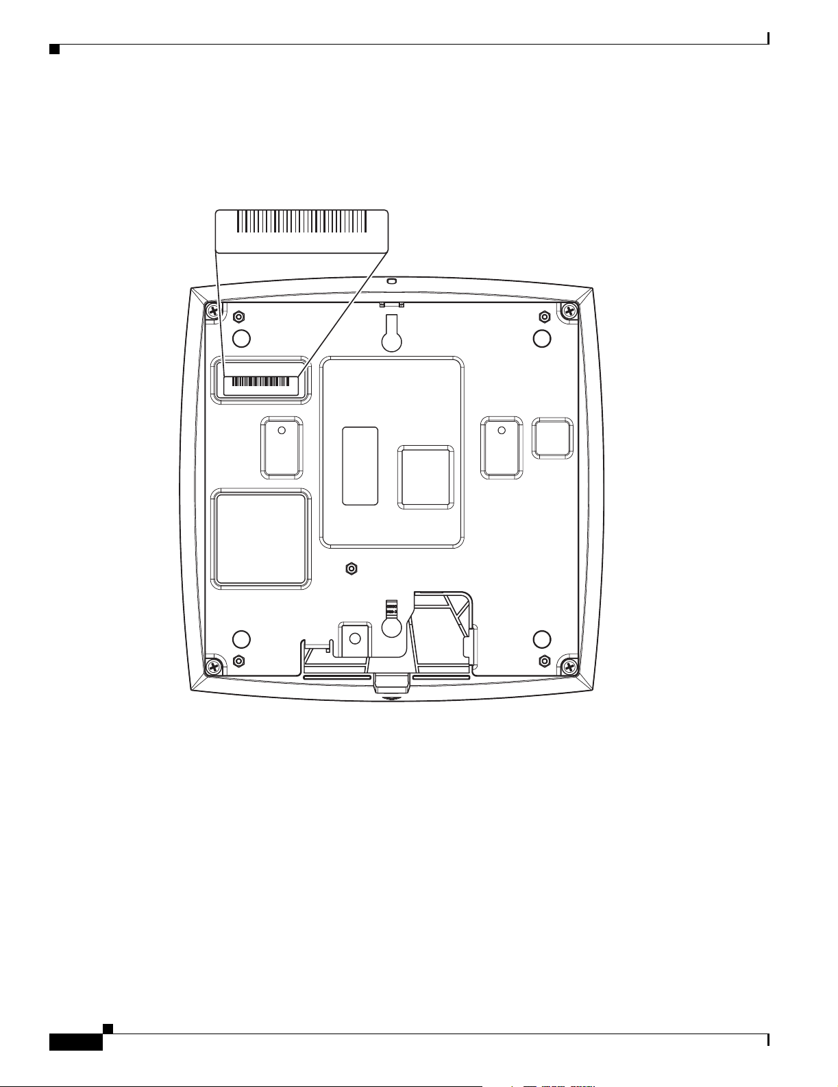
Locating the Product Serial Number
The access point serial number is on the bottom of the housing (refer to Figure 1).
Figure 1 Location of Serial Number Label ---- TBD ----
SN: AAANNNNXXXX
SN: AAANNNNXXXX
Preface
viii
121967 781-00295-01 A0
The access point serial number label contains the following information:
• Model number, such as AIR-AP1240AG-x-k9
• Serial number, such as VDF0636XXXX (11 alphanumeric digits)
• MAC address, such as 00abc65094f3 (12 hexadecimal digits)
• Location of manufacture, such as Made in Singapore
You need your product serial number when requesting support from the Cisco Technical Assistance
Center.
Cisco Aironet 1240AG Series Access Point Hardware Installation Guide
OL-7293-01
Page 17

Preface
Obtaining Technical Assistance
Cisco Technical Support provides 24-hour-a-day award-winning technical assistance. The Cisco
Technical Support & Documentation website on Cisco.com features extensive online support resources.
In addition, if you have a valid Cisco service contract, Cisco Technical Assistance Center (TAC)
engineers provide telephone support. If you do not have a valid Cisco service contract, contact your
reseller.
Cisco Technical Support & Documentation Website
The Cisco Technical Support & Documentation website provides online documents and tools for
troubleshooting and resolving technical issues with Cisco products and technologies. The website is
available 24 hours a day, at this URL:
http://www.cisco.com/techsupport
Access to all tools on the Cisco Technical Support & Documentation website requires a Cisco.com user
ID and password. If you have a valid service contract but do not have a user ID or password, you can
register at this URL:
Obtaining Technical Assistance
http://tools.cisco.com/RPF/register/register.do
Note Use the Cisco Product Identification (CPI) tool to locate your product serial number before submitting
a web or phone request for service. You can access the CPI tool from the Cisco Technical Support &
Documentation website by clicking the Tools & Resources link under Documentation & Tools. Choose
Cisco Product Identification Tool from the Alphabetical Index drop-down list, or click the Cisco
Product Identification Tool link under Alerts & RMAs. The CPI tool offers three search options: by
product ID or model name; by tree view; or for certain products, by copying and pasting show command
output. Search results show an illustration of your product with the serial number label location
highlighted. Locate the serial number label on your product and record the information before placing a
service call.
Submitting a Service Request
Using the online TAC Service Request Tool is the fastest way to open S3 and S4 service requests. (S3
and S4 service requests are those in which your network is minimally impaired or for which you require
product information.) After you describe your situation, the TAC Service Request Tool provides
recommended solutions. If your issue is not resolved using the recommended resources, your service
request is assigned to a Cisco engineer. The TAC Service Request Tool is located at this URL:
http://www.cisco.com/techsupport/servicerequest
For S1 or S2 service requests or if you do not have Internet access, contact the Cisco TAC by telephone.
(S1 or S2 service requests are those in which your production network is down or severely degraded.)
Cisco engineers are assigned immediately to S1 and S2 service requests to help keep your business
operations running smoothly.
To open a service request by telephone, use one of the following numbers:
Asia-Pacific: +61 2 8446 7411 (Australia: 1 800 805 227)
EMEA: +32 2 704 55 55
USA: 1 800 553-2447
OL-7293-01
Cisco Aironet 1240AG Series Access Point Hardware Installation Guide
ix
Page 18

Obtaining Additional Publications and Information
For a complete list of Cisco TAC contacts, go to this URL:
http://www.cisco.com/techsupport/contacts
Definitions of Service Request Severity
To ensure that all service requests are reported in a standard format, Cisco has established severity
definitions.
Severity 1 (S1)—Your network is “down,” or there is a critical impact to your business operations. You
and Cisco will commit all necessary resources around the clock to resolve the situation.
Severity 2 (S2)—Operation of an existing network is severely degraded, or significant aspects of your
business operation are negatively affected by inadequate performance of Cisco products. You and Cisco
will commit full-time resources during normal business hours to resolve the situation.
Severity 3 (S3)—Operational performance of your network is impaired, but most business operations
remain functional. You and Cisco will commit resources during normal business hours to restore service
to satisfactory levels.
Severity 4 (S4)—You require information or assistance with Cisco product capabilities, installation, or
configuration. There is little or no effect on your business operations.
Preface
Obtaining Additional Publications and Information
Information about Cisco products, technologies, and network solutions is available from various online
and printed sources.
• Cisco Marketplace provides a variety of Cisco books, reference guides, documentation, and logo
merchandise. Visit Cisco Marketplace, the company store, at this URL:
http://www.cisco.com/go/marketplace/
• Cisco Press publishes a wide range of general networking, training and certification titles. Both new
and experienced users will benefit from these publications. For current Cisco Press titles and other
information, go to Cisco Press at this URL:
http://www.ciscopress.com
• Pack et magazine is the Cisco Systems technical user magazine for maximizing Internet and
networking investments. Each quarter, Packet delivers coverage of the latest industry trends,
technology breakthroughs, and Cisco products and solutions, as well as network deployment and
troubleshooting tips, configuration examples, customer case studies, certification and training
information, and links to scores of in-depth online resources. You can access Packet magazine at
this URL:
http://www.cisco.com/packet
• iQ Magazine is the quarterly publication from Cisco Systems designed to help growing companies
learn how they can use technology to increase revenue, streamline their business, and expand
services. The publication identifies the challenges facing these companies and the technologies to
help solve them, using real-world case studies and business strategies to help readers make sound
technology investment decisions. You can access iQ Magazine at this URL:
http://www.cisco.com/go/iqmagazine
or view the digital edition at this URL:
http://ciscoiq.texterity.com/ciscoiq/sample/
Cisco Aironet 1240AG Series Access Point Hardware Installation Guide
x
OL-7293-01
Page 19

Preface
Obtaining Additional Publications and Information
• Internet Protocol Journal is a quarterly journal published by Cisco Systems for engineering
professionals involved in designing, developing, and operating public and private internets and
intranets. You can access the Internet Protocol Journal at this URL:
http://www.cisco.com/ipj
• Networking products offered by Cisco Systems, as well as customer support services, can be
obtained at this URL:
http://www.cisco.com/en/US/products/index.html
• Networking Professionals Connection is an interactive website for networking professionals to share
questions, suggestions, and information about networking products and technologies with Cisco
experts and other networking professionals. Join a discussion at this URL:
http://www.cisco.com/discuss/networking
• World-class networking training is available from Cisco. You can view current offerings at
this URL:
http://www.cisco.com/en/US/learning/index.html
OL-7293-01
Cisco Aironet 1240AG Series Access Point Hardware Installation Guide
xi
Page 20

Obtaining Additional Publications and Information
Preface
xii
Cisco Aironet 1240AG Series Access Point Hardware Installation Guide
OL-7293-01
Page 21

CHA P TER
1
Overview
Cisco Aironet 1240AG Series Access Points combine mobility and flexibility with the enterprise-class
features required by networking professionals. With a management system based on Cisco IOS software,
the 1240AG series access point is a Wi-Fi certified, wireless LAN transceiver.
The access point contains two integrated radios: a 2.4-GHz radio (IEEE 802.11g) and a 5-GHz radio
(IEEE 802.11a). You can configure the radios separately, using different settings on each.
The access point connects wireless and wired networks or is the center point of a stand-alone wireless
network. In large installations, wireless users within radio range of an access point can roam throughout
a facility while maintaining seamless, uninterrupted access to the network.
You can configure and monitor the access point using the command-line interface (CLI), the
browser-based management system, Simple Network Management Protocol (SNMP), or Cisco
Structured Wireless-Aware Network (SWAN).
This chapter provides information on the following topics:
• Hardware Features, page 1-2
• Network Configuration Examples, page 1-8
OL-7293-01
Cisco Aironet 1240AG Series Access Point Hardware Installation Guide
1-1
Page 22
Hardware Features
Hardware Features
Key hardware features of the access point include:
• Dual-radio operation (see page 1-4)
• Ethernet port (see page 1-4)
• Console port (see page 1-5)
• LEDs, (see page 1-5)
• Multiple power sources (see page 1-5)
• UL 2043 certification (see page 1-6)
• Anti-theft features (see page 1-6)
Refer to Appendix C, “Access Point Specifications,” for a list of access point specifications.
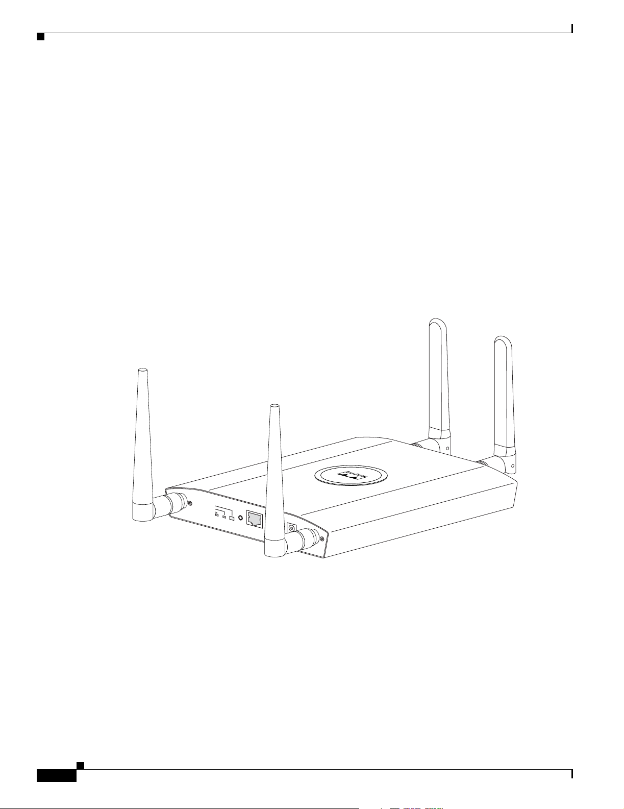
Figure 1-2 shows the access point with antennas.
Figure 1-1 Access Point With Antennas
Chapter 1 Overview
1-2
STATU S
ETHERNET
RADIO
MODE
CONSOLE
ETHERNET
48VDC
2.4 GHz RIGHT / PRIMARY
2.4 GHz LEFT
Cisco Aironet 1240AG Series Access Point Hardware Installation Guide
135434
OL-7293-01
Page 23
Chapter 1 Overview
Hardware Features
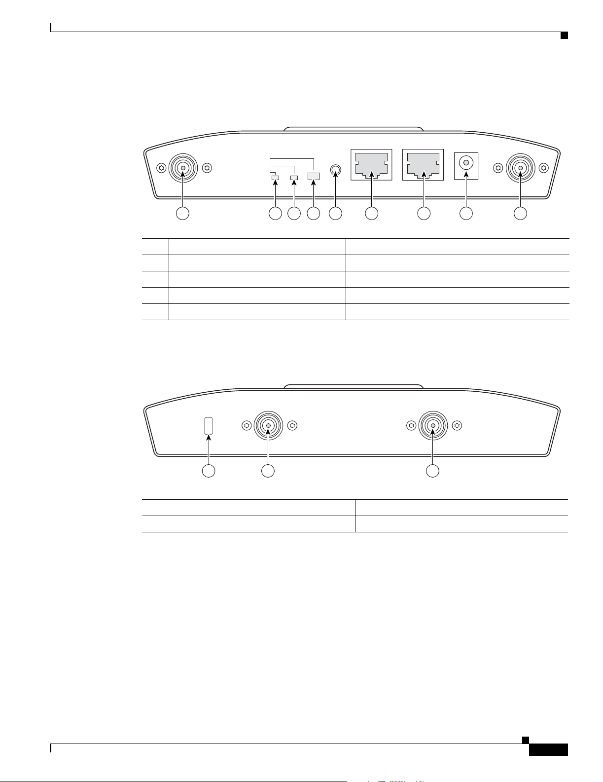
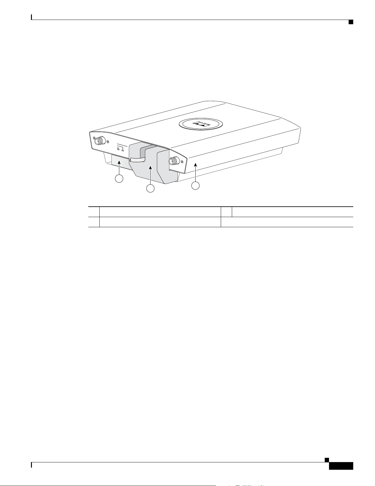
Figure 1-2 illustrates the 2.4-GHz connector end of the access point.
Figure 1-2 Access Point 2.4 GHz Connector End
2.4 GHz LEFT
STATUS
RADIO
ETHERNET
CONSOLE
MODE
ETHERNET
48VDC
2.4 GHz RIGHT/PRIMARY
6 7 8 91 5432
1 2.4-GHz antenna connector (left) 6 Console port (RJ-45)
2 Ethernet LED 7 Ethernet port (RJ-45)
3 Radio LED 8 48-VDC power port
4 Status LED 9 2.4-GHz antenna connector (right/primary)
5 Mode button
Figure 1-3 illustrates the 5-GHz connector end of the access point.
Figure 1-3 Access Point 5-GHz Connector End
5 GHz ANTENNA w/RP-TNC
135435
LEFT
1
RIGHT / PRIMARY
23
1 5-GHz antenna connector (left) 3 Security key slot
2 5-GHz antenna connector (right/primary)
135436
OL-7293-01
Cisco Aironet 1240AG Series Access Point Hardware Installation Guide
1-3
Page 24

Hardware Features
Dual-Radio Operation
The access point supports simultaneous radio operation using a 2.4-GHz 802.11g radio and a 5-GHz
802.11a radio. Each radio uses dual-diversity integrated antennas.
The 5-GHz radio incorporates an Unlicensed National Information Infrastructure (UNII) radio
transceiver operating in the UNII 5-GHz frequency bands. The 802.11g radio is called Radio0 and the
802.11a radio is called Radio1.
Note In Cisco IOS Release 12.3(7)JA and later, the access point radios are disabled by default, and there is no
default SSID. You must create an SSID and enable the radios before the access point allows wireless
associations from other devices.
Antennas Supported
Table 1-1 lists the supported access point antennas.
Table 1-1 Supported Antennas
Chapter 1 Overview
Ethernet Port
Gain
2.4-GHz Antennas
Diversity ceiling omnidirectional 2 Articulated omnidirectional 3.5
Articulated dipole 2.2 Diversity omnidirectional 4.5
Ceiling omnidirectional 5.2 Omnidirectional 6
Wall patch directional 6 Diversity patch directional 7
Mast mount omnidirectional 5.2 Patch directional 9.5
Diversity pillar omnidirectional 5.2
Diversity patch directional 6.5
Patch directional 9
Yagi directional 10
The auto-sensing Ethernet port (see Figure 1-2) accepts an RJ-45 connector, linking the access point to
your 10BASE-T or 100BASE-T Ethernet LAN. The access point can receive power through the Ethernet
cable from a power injector, switch, or power patch panel. The Ethernet MAC address is printed on the
label on the back of the access point (refer to the “Locating the Product Serial Number” section on
page -viii).
(dBi) 5-GHz Antennas
Gain
(dBi)
1-4
Cisco Aironet 1240AG Series Access Point Hardware Installation Guide
OL-7293-01
Page 25

Chapter 1 Overview
Console Port
Note After completing your configuration changes, you must remove the serial cable from the access point.
LEDs
Hardware Features
The serial console port provides access to the access point’s command-line interface (CLI) using a
terminal emulator program. The port is located on the end of the unit (see Figure 1-2). Use an RJ-45 to
DB-9 serial cable to connect your computer’s COM port to the access point’s serial console port. (Refer
to Appendix E, “Console Cable Pinouts,” for a description of the console port pinouts.) Assign the
following port settings to a terminal emulator to open the management system pages: 9600 baud, 8 data
bits, No parity, 1 stop bit, and no flow control.
The access point has three LEDs (see Figure 1-2) to indicate Ethernet activity, radio activity, and status
indications (refer to the “Checking the Access Point LEDs” section on page 6-2 for additional
information).
• The Status LED provides general operating status and error indications.
• The Ethernet LED signals Ethernet traffic on the wired Ethernet LAN and provides Ethernet error
indications.
Power Sources
Warning
Caution Be careful when handling the access point; the bottom plate might be hot.
• The Radio LED signals that wireless packets are being transmitted or received over the radio
interface and provides radio error indications.
The access point can receive power from an external power module or from inline power using the
Ethernet cable. The access point supports the IEEE 802.3af inline power standard and Cisco CDP Power
Negotiation. Using inline power, you do not need to run a power cord to the access point because power
is supplied over the Ethernet cable.
This product must be connected to a Power over Ethernet (PoE) IEEE 802.3af compliant power source
or an IEC60950 compliant limited power source.
Statement 353
The access point supports the following power sources:
• Power module
• Inline power:
–
Cisco Aironet Power Injector (AIR-PWRINJ3 or AIR-PWRINJ-FIB)
–
An inline power capable switch, such as the Cisco Catalyst 3550 PWR XL, 3560-48PS,
3570-48PS, 4500 with 802.3AF PoE module, or the 6500 with 802.3AF PoE module
OL-7293-01
Cisco Aironet 1240AG Series Access Point Hardware Installation Guide
1-5
Page 26
Hardware Features
Note Some switches and patch panels might not provide enough power to operate the access point with both
2.4-GHz and 5-GHz radios. At power-up, if the access point is unable to determine that the power source
can supply sufficient power, the access point automatically deactivates both radios to prevent an
over-current condition. The access point also activates a Status LED low power error indication and
creates an error log entry (refer to the “Checking the Access Point LEDs” section on page 6-2 and the
“Low Power Condition” section on page 6-5).
UL 2043 Certification
The access point has adequate fire resistance and low smoke-producing characteristics suitable for
operation in a building's environmental air space, such as above suspended ceilings, in accordance with
Section 300-22(c) of the NEC, and with Sections 2-128, 12-010(3) and 12-100 of the Canadian
Electrical Code, Part 1, C22.1.
Caution Only the fiber-optic power injector (AIR-PWRINJ-FIB) has been tested to UL 2043 for operation in a
building’s environmental air space; the AIR-PWRINJ3 power injector and the power module are not
tested to UL 2043 and should not be placed in a building’s environmental air space, such as above
suspended ceilings.
–
Other inline power switches supporting the IEEE 802.3af inline power standard
Chapter 1 Overview
Anti-Theft Features
There are three methods of securing the access point:
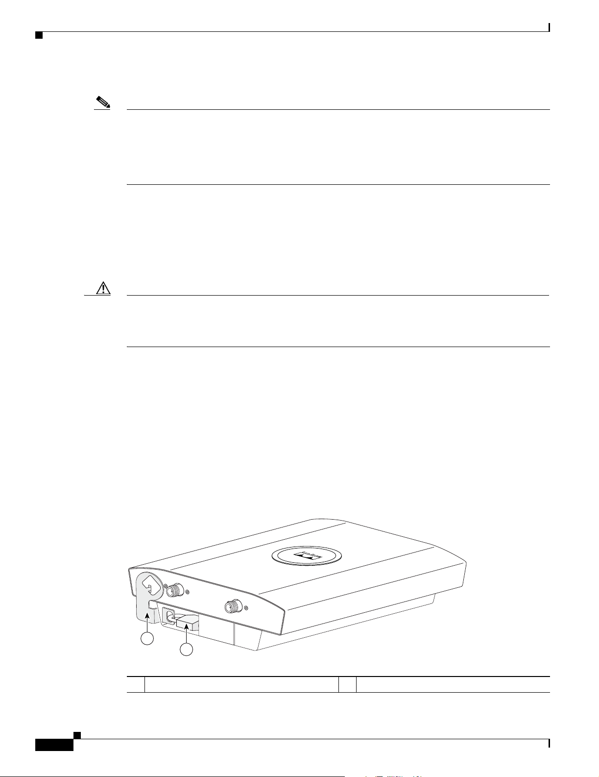
Figure 1-4 Access Point with Security Hasp and Padlock
• Security cable keyhole—You can use the security cable slot (see Figure 1-3) to secure the access
point using a standard security cable, like those used on laptop computers (refer to the “Using a
Security Cable” section on page 2-19).
• Security hasp—When you mount the access point on a wall or ceiling using the mounting plate and
the security hasp, you can lock the access point to the plate with a padlock (see Figure 1-4).
Compatible padlocks are Master Lock models 120T and 121T or equivalent.
135442
2.4 GHz LEFT
2.4 GHz RIGHT / PRIMARY
1
2
1-6
1 Security hasp 2 Security padlock
Cisco Aironet 1240AG Series Access Point Hardware Installation Guide
OL-7293-01
Page 27
Chapter 1 Overview
Hardware Features
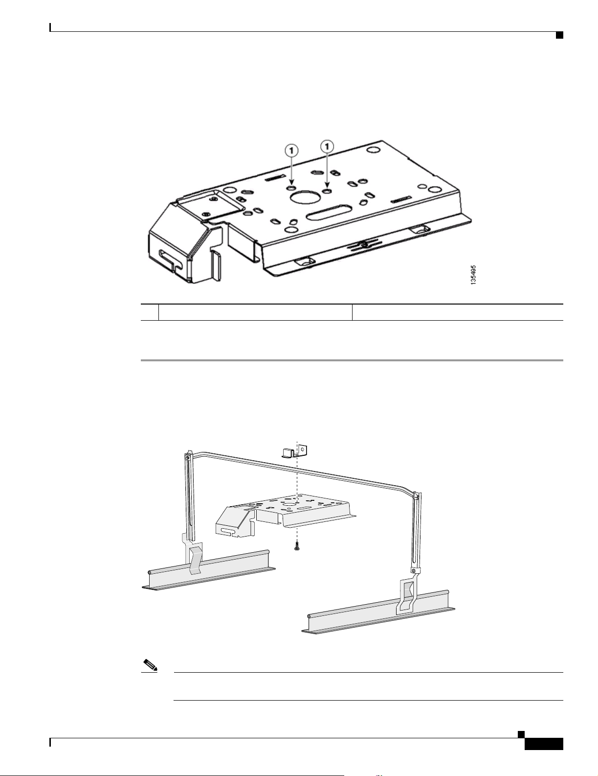
• Cable security bracket—The cable security bracket (see Figure 1-5) attaches to the mounting plate
and covers the console port, Ethernet port, power port, and the mode button to prevent the
installation or removal of the cables or the activation of the mode button. The cable security bracket
is user removable prior to attaching the mounting plate to a ceiling or wall.
Figure 1-5 Access Point with Mounting Plate and Cable Security Bracket
STATU S
2.4 GHz LEFT
RADIO
ETHERNET
ETHERNET
48VDC
2.4 GHz RIGHT / PRIMARY
1
2
3
1 Mounting plate 3 Access point
2 Cable security bracket
135496
OL-7293-01
Cisco Aironet 1240AG Series Access Point Hardware Installation Guide
1-7
Page 28
Network Configuration Examples
Network Configuration Examples
This section describes the access point’s role in three common wireless network configurations. The
access point’s default configuration is as a root unit connected to a wired LAN or as the central unit in
an all-wireless network. The repeater role requires a specific configuration.
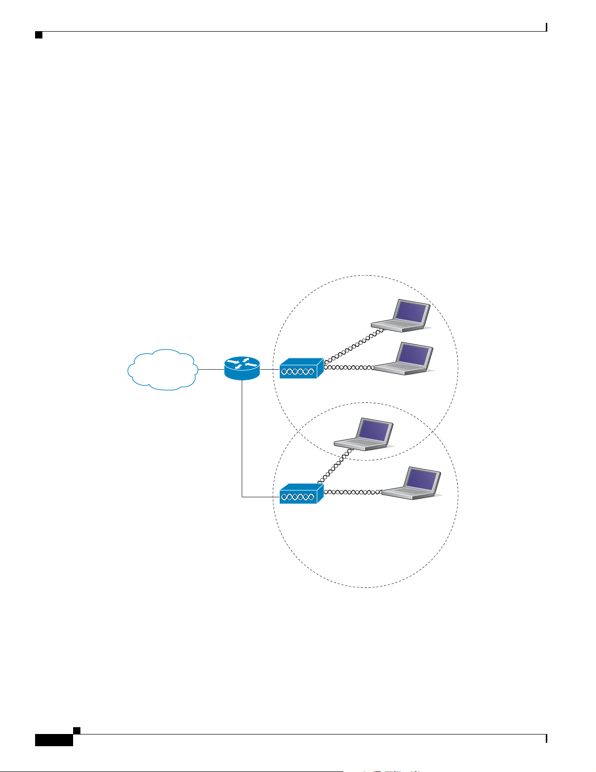
Root Unit on a Wired LAN
An access point connected directly to a wired LAN provides a connection point for wireless users. If
more than one access point is connected to the LAN, users can roam from one area of a facility to another
without losing their connection to the network. Figure 1-6 shows access points acting as root units on a
wired LAN.
Figure 1-6 Access Points as Root Units on a Wired LAN
Chapter 1 Overview
Access Point
Access Point
135445
1-8
Cisco Aironet 1240AG Series Access Point Hardware Installation Guide
OL-7293-01
Page 29
Chapter 1 Overview
Repeater Unit that Extends Wireless Range
An access point can be configured as a stand-alone repeater to extend the range of your infrastructure or
to overcome an obstacle that blocks radio communication. The repeater forwards traffic between
wireless users and the wired LAN by sending packets to either another repeater or to an access point
connected to the wired LAN. The data is sent through the route that provides the best performance for
the client. Figure 1-7 shows an access point acting as a repeater. Consult the Cisco IOS Software
Configuration Guide for Cisco Aironet Access Points for instructions on setting up an access point as a
repeater.
Note Non-Cisco client devices might have difficulty communicating with repeater access points.
Figure 1-7 Access Point as Repeater
Network Configuration Examples
Access Point Repeater
135444
OL-7293-01
Cisco Aironet 1240AG Series Access Point Hardware Installation Guide
1-9
Page 30
Network Configuration Examples
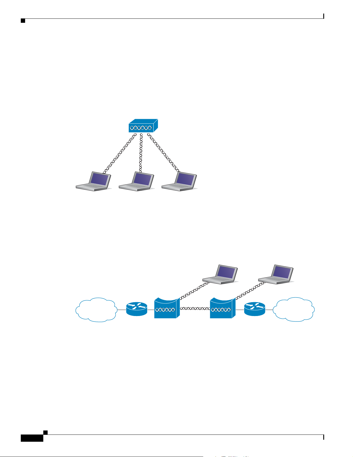
Central Unit in an All-Wireless Network
In an all-wireless network, an access point acts as a stand-alone root unit. The access point is not
attached to a wired LAN; it functions as a hub linking all stations together. The access point serves as
the focal point for communications, increasing the communication range of wireless users. Figure 1-8
shows an access point in an all-wireless network.
Figure 1-8 Access Point as Central Unit in All-Wireless Network
Access Point
Chapter 1 Overview
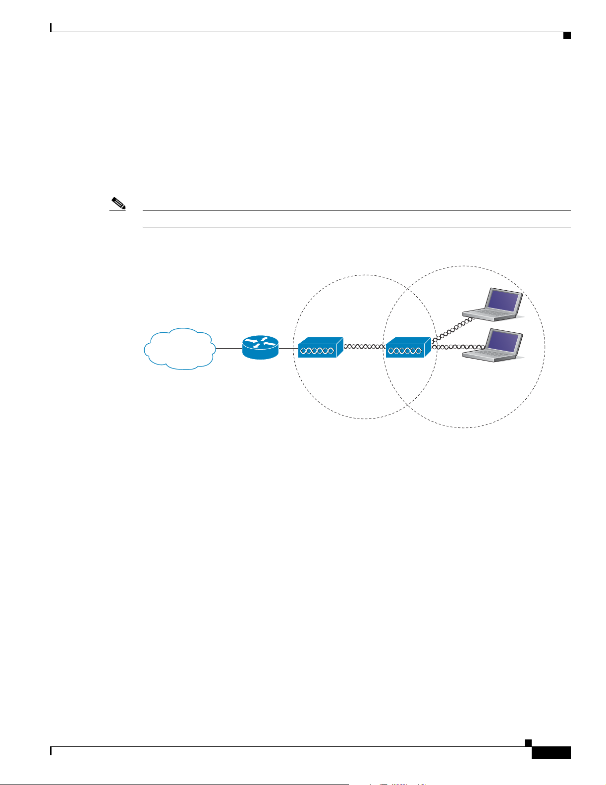
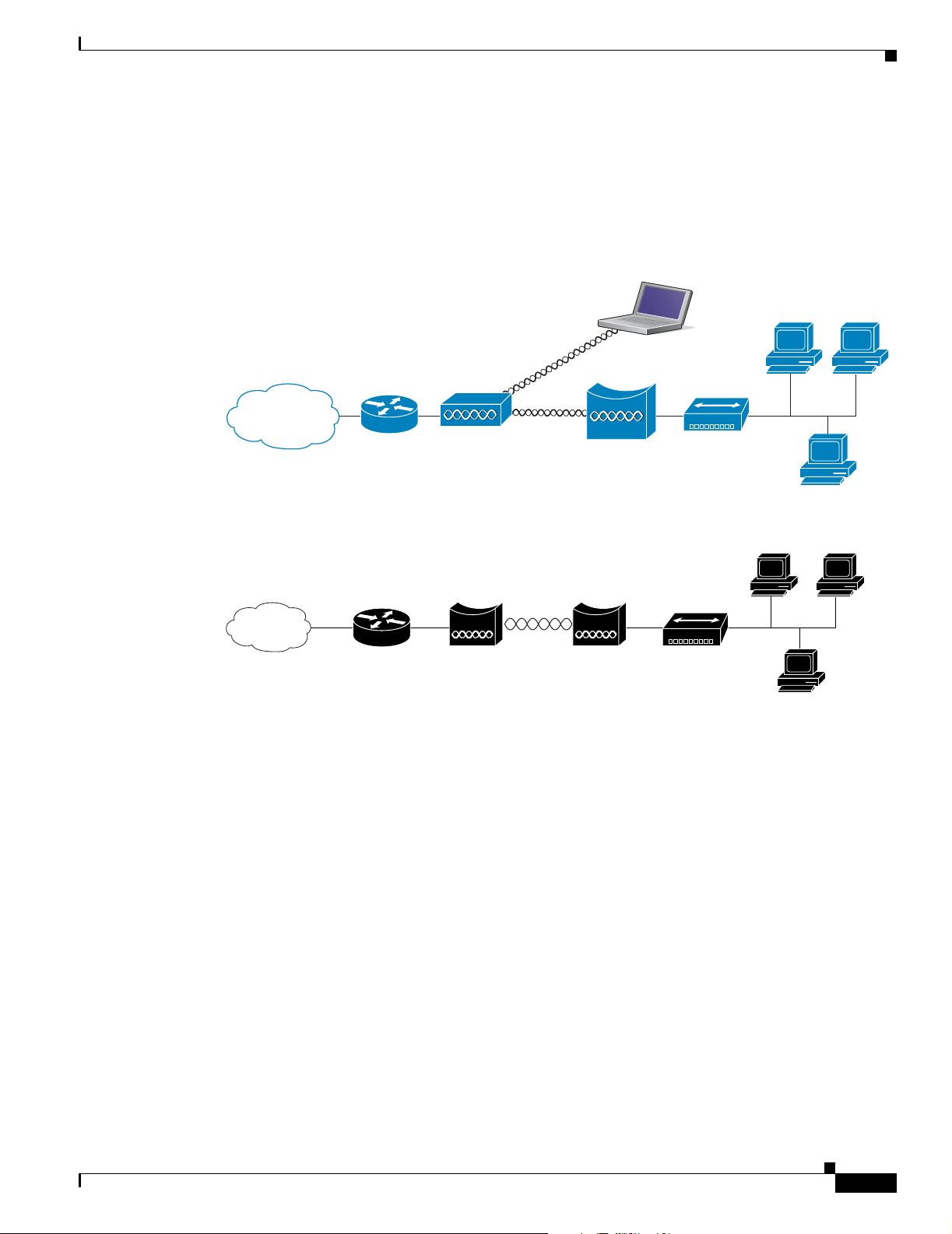
Bridge Network with Wireless Clients
The access point supports root bridge and non-root bridge roles used to interconnect a remote LAN to
the main LAN (see Figure 1-9). The bridge units can also support wireless clients.
Figure 1-9 Root Bridge and Non-root Bridge with Clients
Root bridge Non-root bridge
135443
135446
1-10
Cisco Aironet 1240AG Series Access Point Hardware Installation Guide
OL-7293-01
Page 31
Chapter 1 Overview
Workgroup Bridge Network
The access point supports a workgroup bridge role to interconnect remote Ethernet workstations to the
main LAN. The workgroup bridge can communicate with an access point (see Figure 1-10) or with a
bridge (see Figure 1-11).
Figure 1-10 Workgroup Bridge Communicating with an Access Point
Network Configuration Examples
Access point
Workgroup bridge
Figure 1-11 Workgroup Bridge Communicating with a Bridge
Bridge Workgroup
bridge
135448
135499
OL-7293-01
Cisco Aironet 1240AG Series Access Point Hardware Installation Guide
1-11
Page 32

Network Configuration Examples
Point-to-Point Bridge Configuration
In a point-to-point bridge configuration, two bridges interconnect two LAN networks using a wireless
communication link (see Figure 1-12). The bridge connected to the main LAN network is classified as
a root bridge and the other bridge is classified as a non-root bridge.
Figure 1-12 Point-to-Point Bridge Configuration
Chapter 1 Overview
117029
1-12
Cisco Aironet 1240AG Series Access Point Hardware Installation Guide
OL-7293-01
Page 33

CHA P TER
Installing the Access Point
This chapter describes the installation of the access point and includes these sections:
• Safety Information, page 2-2
• Warnings, page 2-2
• Unpacking the Access Point, page 2-3
• Basic Installation Guidelines, page 2-4
• Before Beginning the Installation, page 2-4
• Installation Summary, page 2-5
• Mounting Overview, page 2-5
• Mounting on a Horizontal or Vertical Surface, page 2-7
• Mounting Below a Suspended Ceiling, page 2-8
• Mounting Above a Suspended Ceiling, page 2-9
• Mounting Access Point on a Desktop or Shelf, page 2-12
2
• Connecting the Ethernet and Power Cables, page 2-13
• Powering Up the Access Point, page 2-15
• Cable Security Bracket, page 2-16
• Attaching the Access Point to the Mounting Plate, page 2-17
• Securing the Access Point, page 2-18
• Securing the Access Point to the Mounting Plate, page 2-19
OL-7293-01
Cisco Aironet 1240AG Series Access Point Hardware Installation Guide
2-1
Page 34

Safety Information
Safety Information
Follow the guidelines in this section to ensure proper operation and safe use of the access point.
FCC Safety Compliance Statement
The FCC with its action in ET Docket 96-8 has adopted a safety standard for human exposure to radio
frequency (RF) electromagnetic energy emitted by FCC certified equipment. When used with approved
Cisco Aironet antennas, Cisco Aironet products meet the uncontrolled environmental limits found in
OET-65 and ANSI C95.1, 1991. Proper installation of this radio according to the instructions found in
this manual will result in user exposure that is substantially below the FCC recommended limits.
General Safety Guidelines
Do not hold any component containing a radio so that the antenna is very close to or touching any
exposed parts of the body, especially the face or eyes, while transmitting.
Chapter 2 Installing the Access Point
Warnings
Warning
Warning
Warning
Warning
Translated versions of the following safety warnings are provided in Appendix A, “Translated Safety
Warnings.”
This warning symbol means danger. You are in a situation that could cause bodily injury. Before you
work on any equipment, be aware of the hazards involved with electrical circuitry and be familiar
with standard practices for preventing accidents. Use the statement number provided at the end of
each warning to locate its translation in the translated safety warnings that accompanied this device.
Statement 1071
SAVE THESE INSTRUCTIONS
Read the installation instructions before you connect the system to its power source.
This product must be connected to a power-over-ethernet (PoE) IEEE 802.3af compliant power source or an
IEC60950 compliant limited power source.
This product relies on the building’s installation for short-circuit (overcurrent) protection. Ensure that
the protective device is rated not greater than: 20A
Statement 353
Statement 1005
Statement 1004
2-2
Warning
Cisco Aironet 1240AG Series Access Point Hardware Installation Guide
Do not operate your wireless network device near unshielded blasting caps or in an explosive
environment unless the device has been modified to be especially qualified for such use.
Statement 245B
OL-7293-01
Page 35

Chapter 2 Installing the Access Point
Unpacking the Access Point
Warning
Warning
In order to comply with FCC radio frequency (RF) exposure limits, antennas should be located at a
minimum of 7.9 inches (20 cm) or more from the body of all persons.
Do not work on the system or connect or disconnect cables during periods of lightning activity.
Statement 1001
Unpacking the Access Point
Follow these steps to unpack the access point:
Step 1 Open the shipping container and carefully remove the contents.
Step 2 Return all packing materials to the shipping container and save it.
Step 3 Ensure that all items listed in the “Package Contents” section are included in the shipment. Check each
item for damage. If any item is damaged or missing, notify your authorized Cisco sales representative.
Package Contents
Statement 332
Each access point package contains the following items:
• Cisco Aironet 1240AG Series Access Point
• Cisco Aironet 1240AG Series Power Module (universal power module)–optional
• Mounting hardware kit
–
One mounting plate with cable security bracket
–
Two suspended ceiling T-rail clips, spacers (accomodates standard and recessed T-rails), and
nuts.
–
One security hasp
–
Two 6 x 32 x 1/2 in. pan head Phillips machine screws
–
Four 8 x 18 x 3/4 in. pan head Phillips sheet metal screws
–
Four #8 plastic wall anchors
–
One 10 x 24 nut (for ground stud on mounting bracket)
–
Four rubber foot pads
–
Two cable tie wraps
• Quick Start Guide: Cisco Aironet 1240AG Series Access Point
• Safety Warnings for Cisco Aironet 1240AG Series Access Points
• Cisco product registration and Cisco documentation feedback cards
OL-7293-01
Cisco Aironet 1240AG Series Access Point Hardware Installation Guide
2-3
Page 36
Basic Installation Guidelines
Basic Installation Guidelines
Because the access point is a radio device, it is susceptible to interference that can reduce throughput
and range. Follow these basic guidelines to ensure the best possible performance:
• Install the access point in an area where metal structures such as shelving units, bookcases, filing
cabinets, and metal gridwork do not block the radio signals to and from the access point.
• Install the access point away from microwave ovens. Microwave ovens operate on the same
frequency as the access point and can cause signal interference.
Before Beginning the Installation
Before you begin the installation, refer to these sections to become familiar with the access point and the
mounting hardware:
• “Access Point Layout and Connectors” section on page 2-4
• “Installation Summary” section on page 2-5
Chapter 2 Installing the Access Point
• “Mounting Overview” section on page 2-5
Caution Be careful when handling the access point; the bottom plate might be hot.
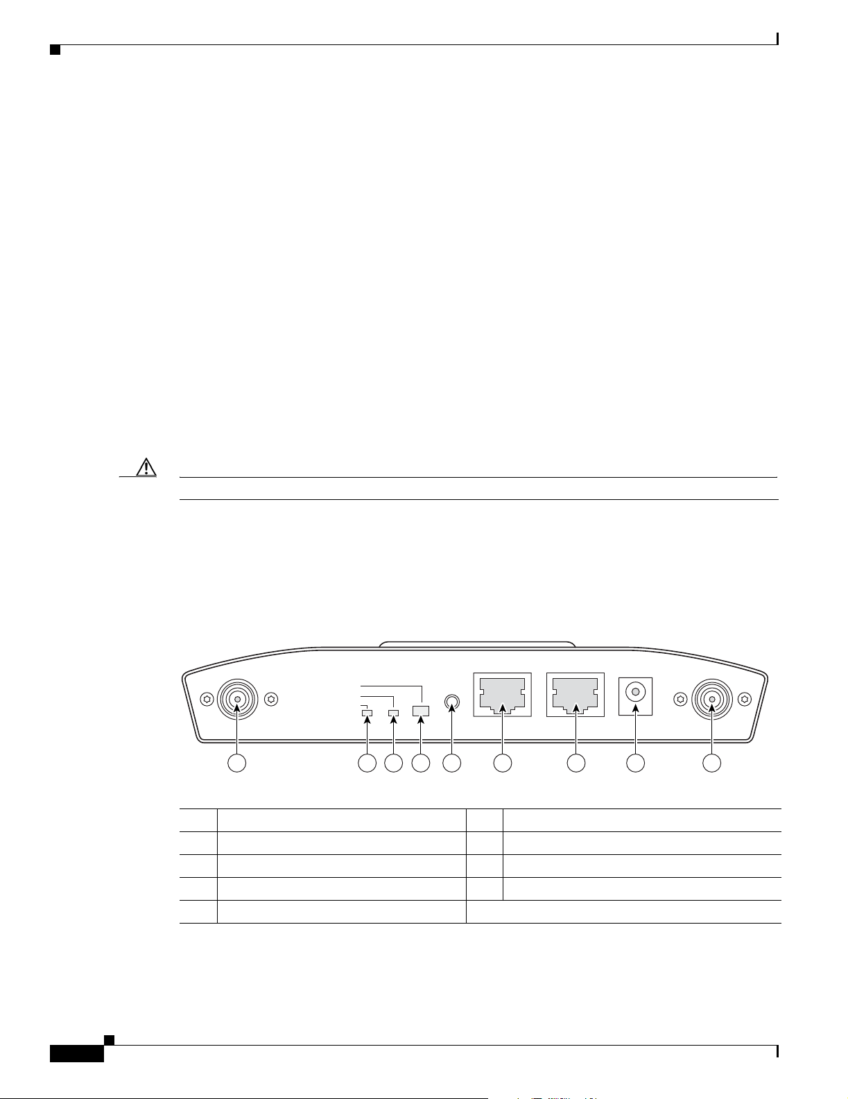
Access Point Layout and Connectors
Figure 2-1 illustrates the 2.4-GHz connector end of the access point.
Figure 2-1 Access Point 2.4 GHz Connector End
STATUS
RADIO
ETHERNET
2.4 GHz LEFT
1 2.4-GHz antenna connector (left) 6 Console port (RJ-45)
2 Ethernet LED 7 Ethernet port (RJ-45)
3 Radio LED 8 48-VDC power port
4 Status LED 9 2.4-GHz antenna connector (right/primary)
5 MODE button
MODE
CONSOLE
6 7 8 91 5432
ETHERNET
48VDC
2.4 GHz RIGHT/PRIMARY
135435
2-4
Cisco Aironet 1240AG Series Access Point Hardware Installation Guide
OL-7293-01
Page 37

Chapter 2 Installing the Access Point
Figure 2-2 illustrates the 5-GHz connector end of the access point.
Figure 2-2 Access Point 5-GHz Connector End
Installation Summary
5 GHz ANTENNA w/RP-TNC
1 5-GHz antenna connector (left) 3 Security key slot )
2 5-GHz antenna connector (right/primary
Installation Summary
While installing the access point, you will perform these operations:
• Mount the mounting plate on a convenient flat horizontal or vertical surface, such as a desktop, book
shelf, file cabinet, wall, ceiling, or suspended ceiling T-rail. See these sections:
–
“Mounting on a Horizontal or Vertical Surface” section on page 2-7
–
“Mounting Below a Suspended Ceiling” section on page 2-8
–
“Mounting Above a Suspended Ceiling” section on page 2-9
–
“Mounting Access Point on a Desktop or Shelf” section on page 2-12).
• Attach the access point to the mounting plate (see the “Attaching the Access Point to the Mounting
Plate” section on page 2-17).
LEFT
1
RIGHT / PRIMARY
135436
23
• Secure the access point (see the “Mounting Below a Suspended Ceiling” section on page 2-8).
• Connect Ethernet and power cables (see the “Connecting the Ethernet and Power Cables” section on
page 2-13).
• Configure basic settings (refer to Chapter 3, “Configuring the Access Point for the First Time”).
• Configure security and other access point options (refer to the Cisco IOS Software Configuration
Guide for Cisco Aironet Access Points).
Mounting Overview
You can mount the access point on any of the following surfaces:
• Horizontal or vertical flat surfaces, such as walls or ceilings
• Suspended ceilings (above and below)
Caution To prevent damage, the unit and the power source (power injector or power module) must be located in
a sheltered environment.
OL-7293-01
Cisco Aironet 1240AG Series Access Point Hardware Installation Guide
2-5
Page 38
Mounting Overview
Chapter 2 Installing the Access Point
The access point ships with a detachable mounting plate and the necessary mounting hardware. Because
it is detachable, you can use the mounting plate as a template to mark the positions of the mounting holes
for your installation. You then install the mounting plate and attach the access point when you are ready.
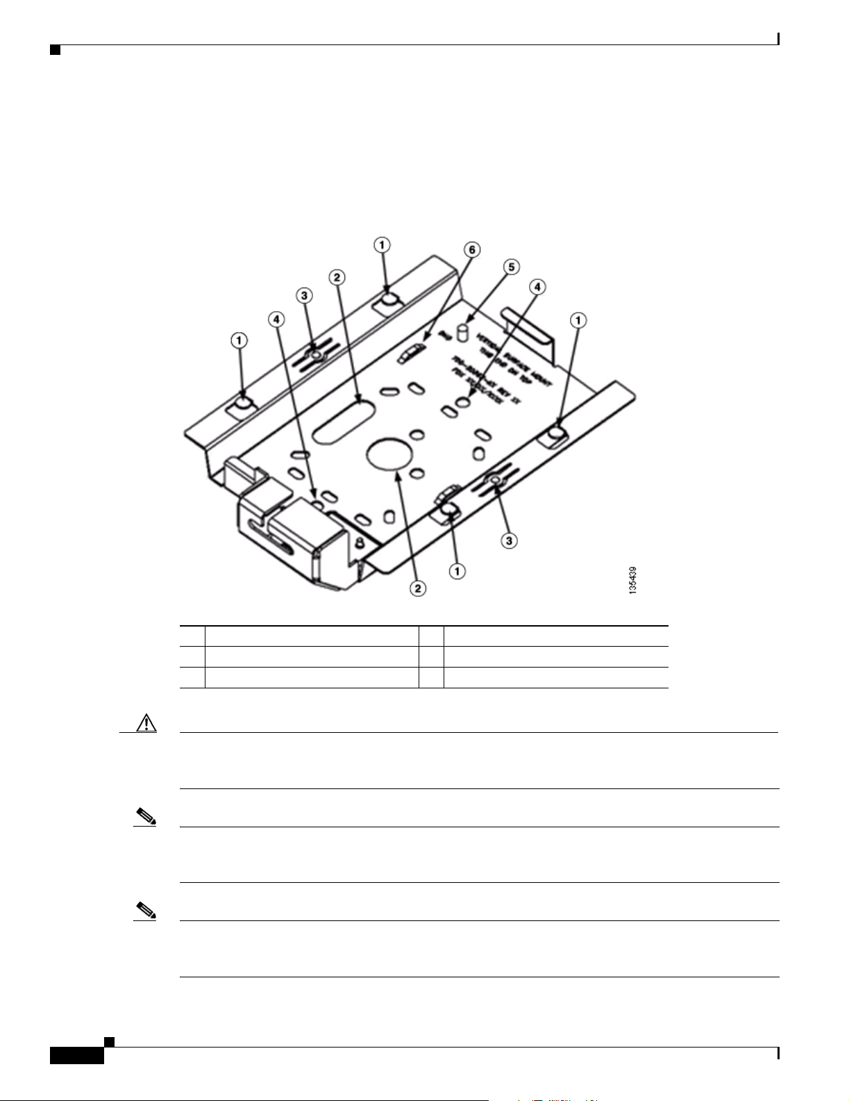
Refer to Figure 2-3 to locate the various mounting holes for the method you intend to use.
Figure 2-3 Mounting Plate
2-6
1 Key hole clips 4 Ceiling or wall mounting holes
2 Cable access openings 5 Ground connection
3 Locking detent 6 Cable tie point
Caution Only the fiber-optic power injector (AIR-PWRINJ-FIB) has been tested to UL 2043 for operation in a
building’s environmental air space; no other power injectors or power modules have been tested to UL 2043
and they should not be placed in a building’s environmental air space, such as above suspended ceilings.
Note The Cisco Aironet 1240AG Series Access Point provides adequate fire resistance and low
smoke-producing characteristics suitable for operation in a building's environmental air space (such as
above suspended ceilings) in accordance with Section 300-22(C) of the National Electrical Code (NEC).
Note When mounting the access point in a building’s environmental air space, you must use Ethernet cable
suitable for operation in environmental air space in accordance with Section 300-22(C) of the National
Electrical Code (NEC).
Cisco Aironet 1240AG Series Access Point Hardware Installation Guide
OL-7293-01
Page 39

Chapter 2 Installing the Access Point
A mounting hardware kit is provided that contains the hardware and fasteners necessary to mount the
access point. Refer to the Table 2-1 to identify the materials you need to mount your access point, then
go to the section containing the specific mounting procedure.
Table 2-1 Material Needed to Mount Access Point
Mounting Method Materials Required In Kit
Horizontal or vertical surface Four #8 x 1 in. (25.4 mm) screws
Suspended ceiling Two T-rail clips with studs
Mounting on a Horizontal or Vertical Surface
Four wall anchors
3/16 in. (4.7 mm) or 3/32 in. (2.3 mm) drill bit
Drill
Standard screwdriver
Two plastic spacers
Two 1/4–20 Keps nuts with built-in washers
Standard screwdriver
Appropriate wrench or pliers
Yes
Yes
No
No
No
Yes
Yes
Yes
No
No
Mounting on a Horizontal or Vertical Surface
Follow these steps to mount the access point on a horizontal or vertical surface.
Step 1 Use the mounting plate as a template to mark the locations of the four mounting holes.
Note When mounting on a vertical surface, position the cable security bracket on the bottom.
Step 2 Drill one of the following sized holes at the locations you marked:
• 3/16 in. (4.7 mm) if you are using wall anchors
• 1/8 in. (6.3 mm) if you are not using wall anchors
Step 3 Install the anchors into the wall if you are using them. Otherwise, go to Step 4.
Step 4 Secure the mounting plate to the surface using the #8 fasteners.
Note On a vertical surface, mount the plate with the security hasp slot on the top.
Step 5 Attach the access point to the mounting plate.
Note For a more secure installation you should attach the mounting plate to a stud or major structural
member and use the appropriate fasteners.
OL-7293-01
Cisco Aironet 1240AG Series Access Point Hardware Installation Guide
2-7
Page 40

Mounting Below a Suspended Ceiling
Mounting Below a Suspended Ceiling
Note To comply with NEC code, a #10-24 grounding lug is provided on the mounting plate.
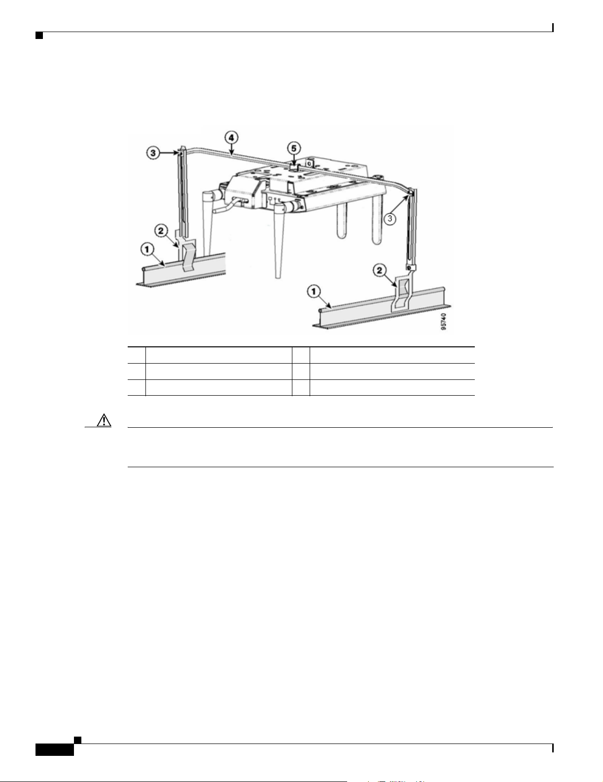
You should review Figure 2-4 before beginning the mounting process.
Figure 2-4 T-Rail Mounting Parts
Chapter 2 Installing the Access Point
2-8
1 Suspended ceiling T-rail 4 mounting plate
2 T-rail clips 5 Keps nut (contains an attached lock washer)
Plastic spacer (used with recessed ceiling
3
tiles)
Cisco Aironet 1240AG Series Access Point Hardware Installation Guide
OL-7293-01
Page 41

Chapter 2 Installing the Access Point
Follow these steps to mount your access point on a suspended ceiling:
Step 1 Decide where you want to mount the access point.
Step 2 Attach two T-rail clips to the suspended ceiling T-rail.
Step 3 Use the mounting plate to adjust the distance between the T-rail clips so that they align with the holes in
the mounting plate.
Step 4 Use a standard screwdriver to tighten the T-rail clip studs in place on the suspended ceiling T-rail. Do
not overtighten.
Step 5 If using recessed ceiling tiles, install a plastic spacer on each T-rail clip stud. The spacer’s legs should
contact the suspended ceiling T-rail.
Step 6 Attach the mounting plate to the T-rail clip studs and start a Keps nut on each stud.
Step 7 Use a wrench or pliers to tighten the Keps nuts. Do not overtighten.
Step 8 To attach the access point to the mounting plate, see the “Attaching the Access Point to the Mounting
Plate” section on page 2-17.
Step 9 If you need additional security, refer to the “Securing the Access Point” section on page 2-18 for
additional information.
Step 10 Verify the access point is operating (see the “Powering Up the Access Point” section on page 2-15).
Mounting Above a Suspended Ceiling
Mounting Above a Suspended Ceiling
The access point mounting plate is designed to be integrated into the T-bar grid above the tiles of a
suspended ceiling. Using a T-bar box hanger and bracket mounting clip (not supplied) such as the
Erico 512A and BHC, you orient the access point antenna just above the top surface of a standard ceiling
tile. You may need to modify a thicker tile to allow room for the antenna.
OL-7293-01
Cisco Aironet 1240AG Series Access Point Hardware Installation Guide
2-9
Page 42
Mounting Above a Suspended Ceiling
It may be helpful to refer to Figure 2-5 before proceeding.
Figure 2-5 Above Suspended Ceiling Parts ------ TBD ------
Chapter 2 Installing the Access Point
1
Suspended ceiling T-rail
2
T-rail clip
3
Height adjustment screw
Caution Only the fiber-optic power injector (AIR-PWRINJ-FIB) has been tested to UL 2043 for operation in a
4
T-bar box hanger
5
Bracket mounting clip
building’s environmental air space; no other power injectors or power modules have been tested to UL 2043
and they should not be placed in a building’s environmental air space, such as above suspended ceilings.
2-10
Cisco Aironet 1240AG Series Access Point Hardware Installation Guide
OL-7293-01
Page 43
Chapter 2 Installing the Access Point
The bracket mounting clip requires the use of two mounting clip holes on the mounting plate (see
Figure 2-6).
Figure 2-6 Mounting Plate Holes
Mounting Above a Suspended Ceiling
1 Bracket mounting clip holes
Follow these steps to mount the access point above a suspended ceiling.
Step 1 Insert the bracket mounting clip’s tab into the large hole on the access point mounting plate.
Step 2 Place the clip over the T-bar box hanger and secure it to the access point mounting plate (see Figure 2-7)
with the 1/4-20 fastener (supplied with the T-bar hanger).
Figure 2-7 Access Point Mounting Plate
OL-7293-01
135498
Note The illustration shows the access point mounting plate mounted perpendicular to the T-bar box
hanger. You can also mount the bracket parallel to the T-bar box hanger.
Cisco Aironet 1240AG Series Access Point Hardware Installation Guide
2-11
Page 44

Mounting Access Point on a Desktop or Shelf
Step 3 Determine the location in the ceiling where you will mount the access point and remove an adjacent
ceiling tile.
Step 4 Orient the access point 2-GHz and 5-GHz antennas so that they are pointing down when mounted on the
T-bar Box hanger.
Step 5 Adjust the height of the T-bar box hanger to provide antenna clearance above the ceiling tile using the
height adjusting screws (refer to Figure 2-5).
Step 6 Attach the T-rail clips on each end of the T-bar box hanger to the ceiling grid T-rails. Make sure the clips
are securely attached to the T-rails.
Step 7 Connect a drop wire to a building structural element and through the hole provided in the bracket
mounting clip. This additional support is required in order to comply with the U.S. National Electrical
Safety Code.
Step 8 To attach the access point to the mounting plate, see the “Attaching the Access Point to the Mounting
Plate” section on page 2-17.
Step 9 If you need additional security, see the “Securing the Access Point” section on page 2-18 for additional
information.
Step 10 Verify the access point is operating before replacing the ceiling tile (see the “Powering Up the Access
Point” section on page 2-15).
Chapter 2 Installing the Access Point
Mounting Access Point on a Desktop or Shelf
When placing the access point on a desktop of shelf, the use of the mounting plate is optional. The
mounting plate can be used to shield the user from the hot bottom surface of the access point when
movement of the access point may be necessary. The access point is shipped with four rubber pads that
you can place on the bottom of the access point or the mounting plate to help prevent sliding or
scratching the surface of your desktop or shelf. For information on connecting the access point cables,
see the “Connecting the Ethernet and Power Cables” section on page 2-13.
2-12
Cisco Aironet 1240AG Series Access Point Hardware Installation Guide
OL-7293-01
Page 45
Chapter 2 Installing the Access Point
Connecting the Ethernet and Power Cables
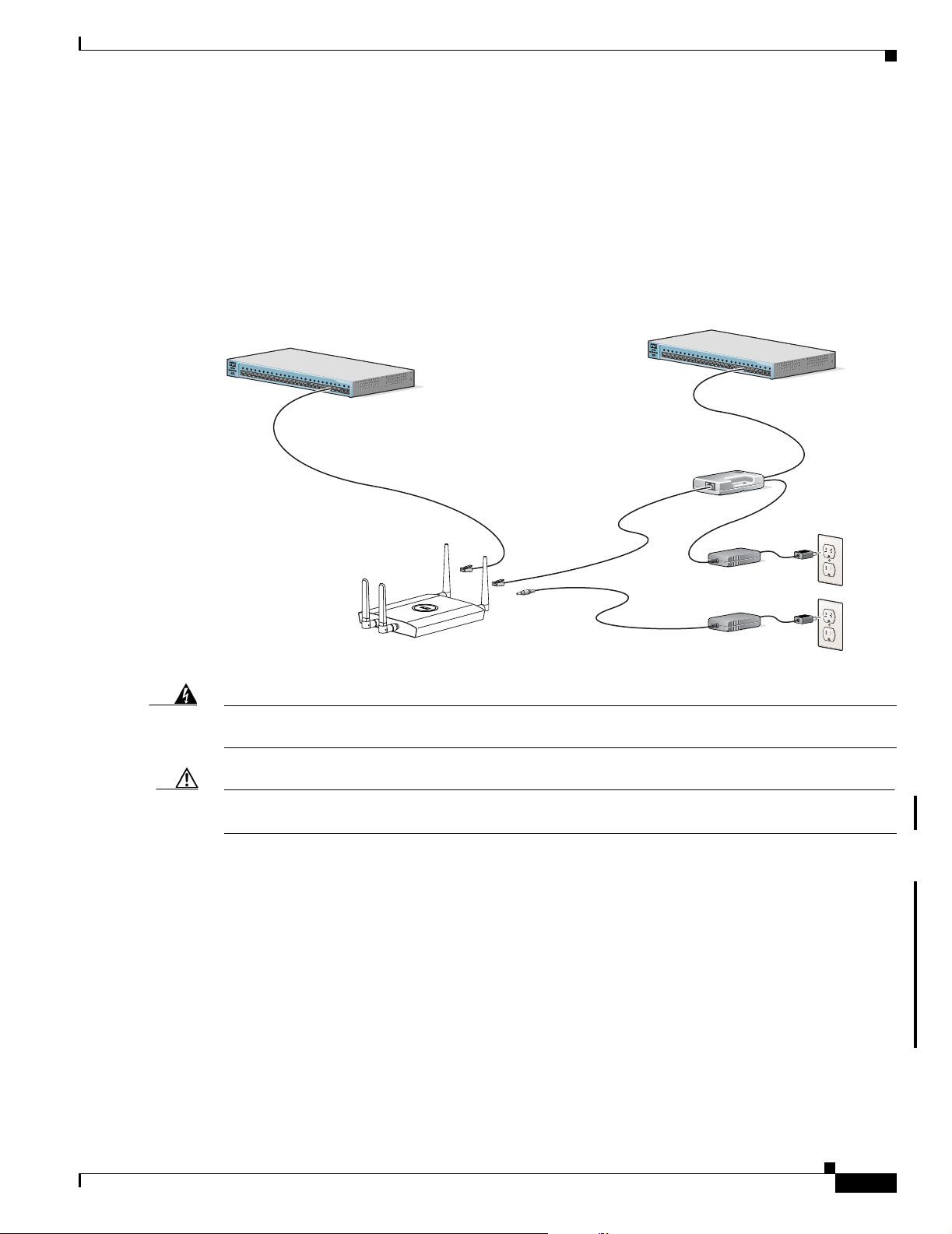
The access point receives power through the Ethernet cable or an external power module. Figure 2-8
shows the power options for the access point.
Figure 2-8 Access Point Power Options
Option 1 Option 2
Switch with
inline power
S
Y
S
T
1
R
P
S
2
3
4
S
T
A
T
5
U
T
I
L
D
U
P
L
X
6
S
P
E
E
D
7
8
1
0
B
a
s
e
9
-
M
O
D
E
T
/
1
0
0
B
a
1
s
0
e
T
X
1
1
1
2
1
3
1
4
1
5
1
6
1
7
18
C
a
ta
ly
st
1
9
2
9
5
0
S
E
R
2
I
E
0
S
21
2
2
1
2
0
3
0
B
a
s
e
F
24
X
2
3
24
Connecting the Ethernet and Power Cables
Switch without
inline power
S
Y
S
T
1
R
P
S
2
3
4
S
T
A
T
5
U
T
I
L
D
U
P
L
X
6
S
P
E
E
D
7
8
1
0
B
a
s
e
9
-
M
O
D
E
T
/
1
0
0
B
a
1
s
0
e
T
X
1
1
1
2
1
3
1
4
1
5
1
6
17
1
8
C
a
ta
ly
s
1
t 2
9
9
5
0
S
E
R
20
I
E
S
21
2
2
1
2
0
3
0
B
a
s
e
F
24
X
23
24
Power injector
K
R
O
W
T
O
E
T
A
P
/
B
N
T
O
R
I
D
G
E
Power
cord
Universal
power supply
Warning
Access Point
This product must be connected to a Power over Ethernet (PoE) IEEE 802.3af compliant power source
or an IEC60950 compliant limited power source.
Statement 353
Option 3
Caution This product and all interconnected equipment must be installed indoors within the same building,
including the associated LAN connections (as defined by Environment A of the IEEE 802.3af standard).
The access point power options:
• Option 1—Switches with sufficient inline power:
–
An inline power capable switch, such as the Cisco Catalyst 3550 PWR XL, 3560-48PS,
3750-48PS, 4500 with 802.3AF PoE module, or the 6500 with 802.3AF PoE module
–
Other inline power switches supporting the IEEE 802.3af inline power standard
135476
OL-7293-01
• Option 2—Switches without sufficient inline power can use the power injector:
–
Cisco Aironet Power Injector (AIR-PWRINJ3 or AIR-PWRINJ-FIB)
• Option 3—Local power using the power module
Cisco Aironet 1240AG Series Access Point Hardware Installation Guide
2-13
Page 46

Chapter 2 Installing the Access Point
Connecting the Ethernet and Power Cables
Note Some older switches and patch panels might not provide enough power to operate the access point. At
power-up, if the access point is unable to determine that the power source can supply sufficient power,
the access point automatically deactivates both radios to prevent an over-current condition. The access
point Status LED turns amber and an error log entry is created (refer to the “Checking the Access Point
LEDs” section on page 6-2 and the “Low Power Condition” section on page 6-5).
Connecting to an Ethernet Network with an Inline Power Source
Caution Be careful when handling the access point; the bottom plate might be hot.
Note If your access point is connected to in-line power, do not connect the power module to the access point.
Using two power sources on the access point might cause the access point to shut down to protect internal
components and might cause the switch to shut down the port to which the access point is connected. If
your access point shuts down, you must remove all power and reconnect only a single power source.
Follow these steps to connect the access point to the Ethernet LAN when you have an inline power
source:
Step 1 Connect a Category 5 Ethernet cable to the RJ-45 Ethernet connector labeled Ethernet on the access
point (see Figure 2-9).
Figure 2-9 Ethernet and Power Ports
2.4 GHz LEFT
STATUS
RADIO
ETHERNET
CONSOLE
MODE
ETHERNET
48VDC
2.4 GHz RIGHT/PRIMARY
1 2
1 Ethernet port 2 48 VDC power port
Step 2
Connect the other end of the Ethernet cable to one of the following:
• A switch with inline power (see the “Connecting the Ethernet and Power Cables” section on
page 2-13).
• The end of a Cisco Aironet power injector labeled To AP/Bridge. Connect the other end labeled To
Network to your 10/100 Ethernet LAN.
135494
2-14
Cisco Aironet 1240AG Series Access Point Hardware Installation Guide
OL-7293-01
Page 47

Chapter 2 Installing the Access Point
Connecting to an Ethernet Network with Local Power
Caution Be careful when handling the access point; the bottom plate might be hot.
Note If your access point is connected to in-line power, do not connect the power module to the access point.
Using two power sources on the access point might cause the access point to shut down to protect internal
components and might cause the switch to shut down the port to which the access point is connected. If
your access point shuts down, you must remove all power and reconnect only a single power source.
Follow these steps to connect the access point to an Ethernet LAN when you are using a local power
source:
Step 1 Connect a Category 5 Ethernet cable to the RJ-45 Ethernet connector labeled Ethernet on the access
point (see Figure 2-9).
Step 2 Connect the power module output connector to the access point’s 48-VDC power port (see Figure 2-9).
Powering Up the Access Point
Step 3 Plug the other end of the Ethernet cable into an unpowered Ethernet port on your LAN network.
Step 4 Plug the other end of the power module into an approved 100- to 240-VAC outlet.
For information on securing your access point, see the “Securing the Access Point” section on page 2-18.
Powering Up the Access Point
When power is applied to the access point, it begins a routine power-up sequence that you can monitor
by observing the three LEDs on the end of the access point. After you observe all three LEDs turning
green to indicate the starting of the IOS operating system, the Status LED blinks green signifying that
IOS is operational. When in an operational status, the Ethernet LED is steady green when no traffic is
being passed and dark during periods when traffic is being passed. The sequence takes about 1 minute
to complete. Refer to Chapter 6, “Troubleshooting,” for LED descriptions.
When the sequence is complete, you are ready to obtain the access point’s IP address and perform an
initial configuration. Refer to Chapter 3, “Configuring the Access Point for the First Time.” for
instructions on assigning basic settings to the access point.
Caution Be careful when handling the access point; the bottom plate might be hot.
OL-7293-01
Note If your access point is connected to in-line power, do not connect the power module to the access point.
Using two power sources on the access point might cause the access point to shut down to protect internal
components and might cause the switch to shut down the port to which the access point is connected. If
your access point shuts down, you must remove all power and reconnect only a single power source.
Cisco Aironet 1240AG Series Access Point Hardware Installation Guide
2-15
Page 48

Cable Security Bracket
Cable Security Bracket
The access point mounting plate has an attached cable security bracket that covers the console port,
Ethernet port, power port, and the mode button to prevent the installation or removal of the cables or the
activation of the mode button. If desired, the cable security bracket can be removed prior to attaching the
mounting plate to a ceiling or wall.
Figure 2-10 Access Point with Mounting Plate and Cable Security Bracket
Chapter 2 Installing the Access Point
STATU S
2.4 GHz LEFT
RADIO
ETHERNET
ETHERNET
48VDC
2.4 GHz RIGHT / PRIMARY
1
2
3
1 Mounting plate 3 Access point
2 Cable security bracket
135496
2-16
Cisco Aironet 1240AG Series Access Point Hardware Installation Guide
OL-7293-01
Page 49

Chapter 2 Installing the Access Point
Removing the Cable Security Bracket
The cable security bracket (see Figure 2-11) is designed to help prevent someone from using the Mode
button to reset the access point to default values or from using the serial console cable to access the
access point’s CLI interface or from removing the Ethernet cable. If this security protection is not
considered necessary, you can remove the cable security bracket.
Figure 2-11 Cable Security Bracket Screws
Attaching the Access Point to the Mounting Plate
1 Cable security bracket 3 Mounting plate
2 Cable security bracket screws
To remove the cable security bracket from the mounting plate, follow these instructions:
Step 1 Position the mounting plate with the cable security bracket pointing down (see Figure 2-11).
Step 2 Remove the two screws that attach the bracket to the mounting plate using a philips screw driver.
Attaching the Access Point to the Mounting Plate
Follow these steps to attach the access point to the mounting plate:
Step 1 If your mounting plate has the cable security bracket, follow these steps:
a. Connect the Ethernet cable to the access point Ethernet port (see the “Connecting the Ethernet and
Power Cables” section on page 2-13).
b. If not using on-line power, connect the power module’s power cable to the access point 48-VDC
connector.
c. Carefully feed the Ethernet and power cables through the cable notch on the cable security bracket
and slide the cables to the right or left to secure the cables (see the “Cable Security Bracket” section
on page 2-16).
OL-7293-01
Cisco Aironet 1240AG Series Access Point Hardware Installation Guide
2-17
Page 50

Securing the Access Point
Note If your access point is connected to Ethernet in-line power, do not connect the local power
Step 2 Line up the four keyhole clips on the mounting plate with the large ends of the keyhole-shaped holes on
the access point.
Note The keyhole clips on each side of the mounting plate are offset and can only be positioned in one
Step 3 Insert the mounting plate clips into the keyhole shaped holes on the access point.
Step 4 Slide the access point towards the cable security bracket end of the mounting bracket while exerting
slight pressure to force the access point and mounting plate together. You will hear a slight click when
the locking detents contact the access point and locks it into place.
Chapter 2 Installing the Access Point
module to the access point. Using two power sources on the access point might cause the access
point to shut down to protect internal components and might cause the switch to shut down the
port to which the access point is connected. If your access point shuts down, you must remove
all power and reconnect only a single power source.
direction onto the access point.
Step 5 Attach and adjust the antenna(s) or antenna cables to the access point antenna connectors.
Note The 5-GHz antennas and antenna cables have a blue dot or blue label. Connect only antennas or
antenna cables with blue dots or labels to the access point’s 5-GHz antenna connectors.
Step 6 If your mounting plate does not have the cable security bracket, follow these steps:
a. Connect a CAT 5 Ethernet cable to the access point Ethernet port (see the “Connecting the Ethernet
and Power Cables” section on page 2-13).
b. If using local power, insert the power module’s power cable into the access point’s 48-VDC power
port.
Note If your access point is connected to in-line power, do not connect the power module to the access
point. Using two power sources on the access point might cause the access point to shut down
to protect internal components and might cause the switch to shut down the port to which the
access point is connected. If your access point shuts down, you must remove all power and
reconnect only a single power source.
Securing the Access Point
2-18
There are two ways to secure your access point:
• Using a security cable
• Securing the access point to the mounting plate
Cisco Aironet 1240AG Series Access Point Hardware Installation Guide
OL-7293-01
Page 51

Chapter 2 Installing the Access Point
Using a Security Cable
You can secure the access point by installing a standard security cable (such as the Kensington Notebook
MicroSaver, model number 64068) into the access point security cable slot (see Figure 2-2). The security
cable can be used with any of the mounting methods described in this guide.
Follow these steps to install the security cable.
Step 1 Loop the security cable around a nearby immovable object.
Step 2 Insert the key into the security cable lock.
Step 3 Insert the security cable latch into the security key slot on the access point.
Step 4 Rotate the key right or left to secure the security cable lock to the access point.
Step 5 Remove the key from security cable lock.
Securing the Access Point to the Mounting Plate
Securing the Access Point
The security hasp enables you to use a padlock to secure the access point to the mounting plate. Known
compatible padlocks are Master Lock models 120T or 121T.
To install the security hasp, follow these steps:
Step 1 Insert the security hasp’s key pin (see Figure 2-12) into the key slot on the access point (see Figure 2-2)
and rotate counterclockwise towards the mounting plate.
Figure 2-12 Security Hasp
135491
2.4 GHz LEFT
1
2
3
4
2.4 GHz RIGHT / PRIMARY
5
6
OL-7293-01
Step 2
1 Key pin 4 Padlock
2 Security hasp 5 5-GHz access point end
3 Mounting plate security slot 6 Mounting plate
Push the security hasp’s padlock flange through the mounting plate’s security slot.
Cisco Aironet 1240AG Series Access Point Hardware Installation Guide
2-19
Page 52

Securing the Access Point
Step 3 Place your padlock (user supplied) through the padlock hole in the security hasp’s padlock flange
(see Figure 2-13).
Figure 2-13 Security Hasp and Padlock
Chapter 2 Installing the Access Point
135442
2.4 GHz LEFT
2.4 GHz RIGHT / PRIMARY
1
2
1 Security hasp 2 Pad lock
Step 4
Push the padlock into the recessed opening between the access point and the mounting plate.
Note When attaching the mounting plate to a vertical surface, place the security cable bracket end of the
mounting plate on the bottom.
2-20
Cisco Aironet 1240AG Series Access Point Hardware Installation Guide
OL-7293-01
Page 53

CHA P TER
3
Configuring the Access Point for the First Time
This chapter describes how to configure basic settings on your access point for the first time. The
contents of this chapter are similar to the instructions in the quick start guide that shipped with your
access point. You can configure all the settings described in this chapter using the CLI, but it might be
simplest to browse to the access point’s web-browser interface to complete the initial configuration and
then use the CLI to enter additional settings for a more detailed configuration.
This chapter contains these sections:
• Before You Start, page 3-2
• Obtaining and Assigning an IP Address, page 3-3
• Connecting to the Access Point Locally, page 3-4
• Assigning Basic Settings, page 3-5
• Enabling the Radio Interfaces, page 3-9
• Finding the IP Address Using the CLI, page 3-13
• Assigning an IP Address Using the CLI, page 3-14
• Using a Telnet Session to Access the CLI, page 3-14
OL-7293-01
Cisco Aironet 1240AG Series Access Point Hardware Installation Guide
3-1
Page 54

Before You Start
Before You Start
Before you install the access point, make sure you are using a computer connected to the same network
as the access point, and obtain the following information from your network administrator:
• A system name for the access point
• The case-sensitive wireless service set identifiers (SSIDs) for your 802.11g and 8002.11a radio
networks
• If not connected to a DHCP server, a unique IP address for your access point (such as 172.17.25.115)
• If the access point is not on the same subnet as your PC, a default gateway address and subnet mask
• A Simple Network Management Protocol (SNMP) community name
• If you plan on using the Cisco IP Setup Utility (IPSU) to find or assign the access point IP address,
the MAC address from the label on the bottom of the access point (such as 00164625854c)
Resetting the Access Point to Default Settings
Chapter 3 Configuring the Access Point for the First Time
Using the Mode Button
If you need to start over during the initial setup process, follow these steps to reset the access point to
factory default settings using the access point MODE button:
Step 1 Disconnect power (the power jack for external power or the Ethernet cable for in-line power) from the
access point.
Step 2 Press and hold the MODE button while you reconnect power to the access point until the Ethernet LED
turns an amber color, approximately 2 to 3 seconds, and release the button. All access point settings
return to factory defaults.
Using the Web-Browser Interface
Prior to using the web-browser interface, you must have the access point IP address (see the “Obtaining
and Assigning an IP Address” section on page 3-3).
Follow these steps to return to default settings using the web-browser interface:
Step 1 Open your web-browser.
Note The access point web-browser interface is fully compatible with Microsoft Internet Explorer
version 6.0 on Windows 98 and 2000 platforms and with Netscape version 7.0 on Windows 98,
Windows 2000, and Solaris platforms.
3-2
Note When using the access point browser interface, you should disable your browser pop-up blocker.
Cisco Aironet 1240AG Series Access Point Hardware Installation Guide
OL-7293-01
Page 55

Chapter 3 Configuring the Access Point for the First Time
Step 2 Enter the access point’s IP address in the browser address line and press Enter. An Enter Network
Password window displays.
Step 3 Enter your username in the User Name field. The default username is Cisco.
Step 4 Enter the access point password in the Password field and press Enter. The default password is Cisco.
The Summary Status page displays.
Step 5 Click System Software and the System Software page displays.
Step 6 Click System Configuration and the System Configuration page displays.
Step 7 To return to factory default settings, click Reset to Defaults.
Step 8 To retain the IP address and return all other settings to factory default values, click
Reset to Defaults (Except IP).
Default IP Address Behavior
When you connect a 1240 series access point running Cisco IOS Release 12.3(7)JA or later software with
a default configuration to your LAN, the access point requests an IP address from your DHCP server
and, if it does not receive an IP address, continues to send requests indefinitely.
Obtaining and Assigning an IP Address
Obtaining and Assigning an IP Address
To browse to the access point’s Express Setup page, you must either obtain or assign the access point’s
IP address using one of the following methods:
Note The access point does not have a default IP address.
• To assign a static IP address to the access point, connect to the access point console port (see the
“Connecting to the Access Point Locally” section on page 3-4) and follow the steps in the
“Assigning an IP Address Using the CLI” section on page 3-14.
• Use a DHCP server (if available) to automatically assign an IP address. You can find out the
DHCP-assigned IP address using one of the following methods:
–
Connect to the access point console port and use a Cisco IOS CLI command to display the IP
address, such as show interface bvi1. Follow the steps in the “Connecting to the Access Point
Locally” section on page 3-4 to connect to the console port.
–
Provide your organization’s network administrator with your access point’s Media Access
Control (MAC) address. Your network administrator will query the DHCP server using the
MAC address to identify the IP address. The access point’s MAC address is on label attached to
the bottom of the access point.
–
Use CLI and the serial port to identify the assigned IP address (refer to the “Finding the IP
Address Using the CLI” section on page 3-13).
OL-7293-01
Cisco Aironet 1240AG Series Access Point Hardware Installation Guide
3-3
Page 56

Connecting to the Access Point Locally
Connecting to the Access Point Locally
If you need to configure the access point locally (without connecting the access point to a wired LAN),
you can connect a PC to its console port using a DB-9 to RJ-45 serial cable.
Caution Be careful when handling the access point, the bottom plate might be hot.
Note After completing your configuration changes, you must remove the serial cable from the access point.
Follow these steps to open the CLI by connecting to the access point console port:
Step 1 Connect a nine-pin, female DB-9 to RJ-45 serial cable to the RJ-45 console port on the access point and
to the COM port on a computer. To connect to the access point console port, you should loop the cable
as shown in Figure 2-9.
Figure 3-1 shows the console port location.
Chapter 3 Configuring the Access Point for the First Time
Figure 3-1 Console Port Location
2.4 GHz LEFT
STATUS
RADIO
ETHERNET
CONSOLE
MODE
ETHERNET
48VDC
2.4 GHz RIGHT/PRIMARY
1
1 Console port
Note The Cisco part number for the DB-9 to RJ-45 serial cable is AIR-CONCAB1200. Browse to
http://www.cisco.com/go/marketplace to order a serial cable.
Step 2 Set up a terminal emulator on your PC to communicate with the access point. Use the following settings
for the terminal emulator connection: 9600 baud, 8 data bits, no parity, 1 stop bit, and no flow control.
135493
3-4
Cisco Aironet 1240AG Series Access Point Hardware Installation Guide
OL-7293-01
Page 57
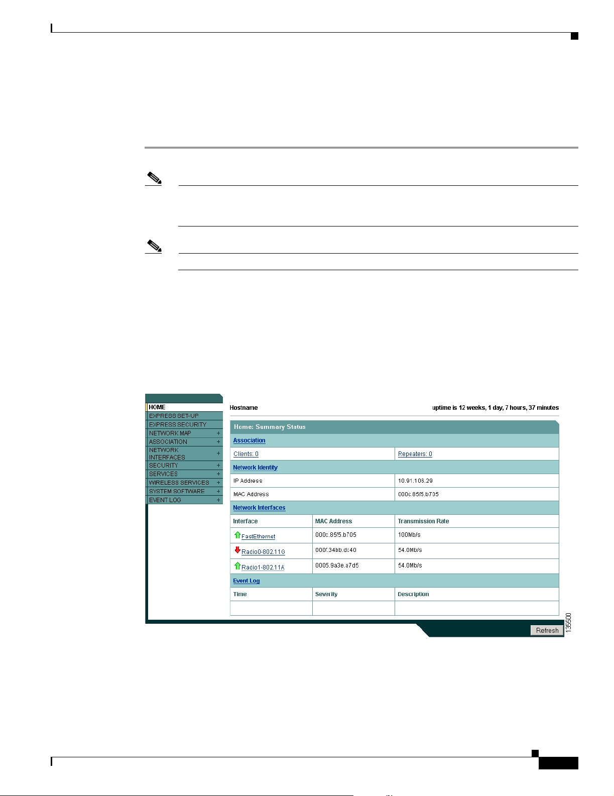
Chapter 3 Configuring the Access Point for the First Time
Assigning Basic Settings
After you determine or assign the access point’s IP address, you can browse to the access point’s Express
Setup page and perform an initial configuration:
Step 1 Open your web-browser.
Note The access point web-browser interface is fully compatible with Microsoft Internet Explorer
version 6.0 on Windows 98 and 2000 platforms, and with Netscape version 7.0 on Windows 98,
Windows 2000, and Solaris platforms.
Note When using the access point browser interface, you should disable your browser pop-up blocker.
Step 2 Enter the access point’s IP address in the browser address line and press Enter. An Enter Network
Password page displays.
Step 3 Enter Cisco in the username field and advance to the Password field.
Step 4 Enter the case-sensitive password Cisco and press Enter. The Summary Status page displays.
Assigning Basic Settings
Figure 3-2 shows the Summary Status page.
Figure 3-2 Summary Status Page
OL-7293-01
Cisco Aironet 1240AG Series Access Point Hardware Installation Guide
3-5
Page 58
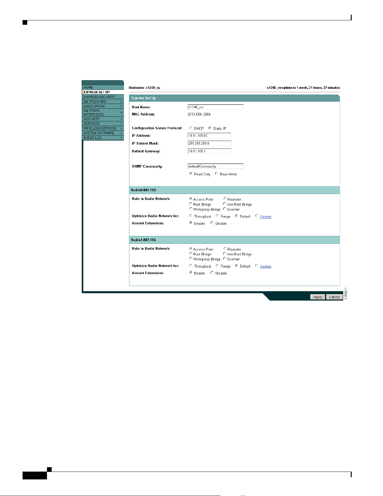
Assigning Basic Settings
Step 5 Click Express Setup. The Express Setup page displays. Figure 3-3 shows the Express Setup page.
Chapter 3 Configuring the Access Point for the First Time
Figure 3-3 Express Setup Page
3-6
Step 6 Enter the configuration settings you obtained from your system administrator. The configurable settings
include:
• Host Name— The host name (or system name), while not an essential setting, helps identify the
access point on your network. The system name displays in the titles of the management system
pages.
• Configuration Server Protocol—Click on the button that matches the network’s method of IP
address assignment.
–
DHCP—IP addresses are automatically assigned by your network’s DHCP server.
–
Static IP—The access point uses a static IP address that you enter in the IP address field.
Cisco Aironet 1240AG Series Access Point Hardware Installation Guide
OL-7293-01
Page 59

Chapter 3 Configuring the Access Point for the First Time
• IP Address—Use this setting to assign or change the access point’s IP address. If DHCP is enabled
for your network, leave this field blank.
Note If the access point’s IP address changes while you are configuring the access point using the
web-browser interface or a Telnet session over the wired LAN, you lose your connection to the
access point. If you lose your connection, reconnect to the access point using its new IP address.
Follow the steps in the “Resetting the Access Point to Default Settings” section on page 3-2 if
you need to start over.
• IP Subnet Mask—Enter the IP subnet mask provided by your network administrator so the IP
address can be recognized on the LAN. If DHCP is enabled, leave this field blank.
• Default Gateway—Enter the default gateway IP address provided by your network administrator.
If DHCP is enabled, leave this field blank.
• Web Server—Choose the type of HTTP protocol used by your web browser to access the access
point.
–
Standard (HTTP)—Uses encrypted traffic to transfer data.
–
Secure (HTTPS)—Uses Secure Socket Layer (SSL) encrypted traffic to transfer data.
• SNMP Community—If your network is using SNMP, enter the SNMP Community name provided
by your network administrator and select the attributes of the SNMP data (also provided by your
network administrator).
Assigning Basic Settings
• Role in Radio Network—Click on the check box that describes the role of the access point on your
network.
–
Access Point—Specifies that the unit operates as an access point connected to the main
Ethernet LAN network. In this mode, wireless client devices are allowed to associate to the
access point.
–
Repeater—Specifies that the unit is not connected to the wired LAN and supports wireless
clients.
–
Root Bridge—Specifies that the unit is operating as a root bridge and connects directly to the
main Ethernet LAN network. In this mode, the unit accepts associations from other Cisco
Aironet non-root bridges and wireless client devices.
–
Non-root Bridge—Specifies that the unit is operating as a non-root bridge and connects to a
remote LAN network and must associate with a Cisco Aironet root bridge using the wireless
interface. The non-root bridge can support wireless client devices.
–
Workgroup Bridge—Specifies that the unit operates as a workgroup bridge connected to a
small wired Ethernet LAN network through an Ethernet hub or switch. The workgroup bridge
must associate to a Cisco Aironet access point or a Cisco Aironet bridge.
–
Scanner—Specifies that the unit is configured by the Cisco WLSE as a wireless scanner and is
reporting network traffic to the Cisco WLSE.
• Optimize Radio Network for—Use this setting to select either preconcerted settings for the access
point radio or customized settings for the access point radio.
–
Throughput—Maximizes the data volume handled by the access point but might reduce its
range.
–
Range—Maximizes the access point’s range but might reduce throughput.
–
Custom—The access point uses settings you enter on the radio settings page. Clicking Custom
takes you to the radio settings page.
OL-7293-01
Cisco Aironet 1240AG Series Access Point Hardware Installation Guide
3-7
Page 60

Assigning Basic Settings
• Aironet Extensions—Enable this setting if there are only Cisco Aironet devices on your wireless
LAN or the unit is operating in repeater mode.
Step 7 Click Apply to save your settings. If you changed the IP address, you lose your connection to the access
point. Browse to the new IP address to reconnect to the access point.
Your access point is now running but probably requires additional configuring to conform to your
network’s operational and security requirements. Consult the chapters in this manual for the information
you need to complete the configuration.
Note You can restore the access point to its factory defaults by unplugging the power jack and
plugging it back in while holding the Mode button down until the Ethernet LED turns an amber
color (approximately 2 to 3 seconds).
Default Settings on the Express Setup Page
Chapter 3 Configuring the Access Point for the First Time
Table 3-1 lists the default settings for the settings on the Express Setup page.
Table 3-1 Default Settings on the Express Setup Page
Setting Default
System Name ap
Configuration Server Protocol DHCP
IP Address Assigned by DHCP
Note The access point does not have a default IP address.
IP Subnet Mask Assigned by DHCP
Default Gateway Assigned by DHCP
Role in Radio Network Access point (root)
Web Server Standard (HTTP)
SNMP Community defaultCommunity
Optimize Radio Network for Throughput
Aironet Extensions Enable
3-8
Cisco Aironet 1240AG Series Access Point Hardware Installation Guide
OL-7293-01
Page 61

Chapter 3 Configuring the Access Point for the First Time
Enabling the Radio Interfaces
In Cisco IOS Release 12.3(7)JA, the access point radios are disabled by default, and there is no default
SSID. You must create an SSID and enable the radios before the access point will allow wireless
associations from other devices. These changes to the default configuration improve the security of
newly installed access points. Refer to the “Configuring Basic Security Settings” section on page 3-9 for
instructions on configuring the SSID.
To enable the radio interfaces, follow these instructions:
Step 1 Use your web-browser to access your access point.
Step 2 When the Summary Status page displays, click Radio0-802.11B or Radio0-802.11G and the 2.4 GHz
radio status page displays.
Step 3 Click Settings and the radio settings page displays.
Step 4 Click Enable in the Enable Radio field.
Step 5 Click Apply.
Step 6 Click Radio1-802.11A and the 5 GHz radio status page displays.
Configuring Basic Security Settings
Step 7 Repeat Steps 3 to 5.
Step 8 Close your web-browser.
Configuring Basic Security Settings
After you assign basic settings to your access point, you must configure security settings to prevent
unauthorized access to your network. Because it is a radio device, the access point can communicate
beyond the physical boundaries of your building.
Just as you use the Express Setup page to assign basic settings, you can use the Express Security page
to create unique SSIDs and assign one of four security types to them. For detail security information,
refer to the Cisco IOS Software Configuration Guide for Cisco Aironet Access Points.
OL-7293-01
Cisco Aironet 1240AG Series Access Point Hardware Installation Guide
3-9
Page 62
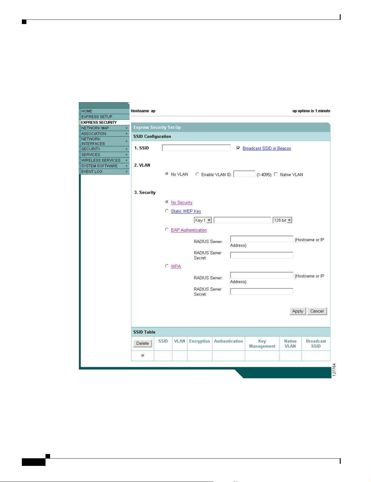
Configuring Basic Security Settings
Configuring Basic Security Settings
You can use the Express Security page to create unique SSIDs and assign one of four security types to
them. Figure 3-4 shows the Express Security page.
Figure 3-4 Express Security Page
Chapter 3 Configuring the Access Point for the First Time
3-10
Cisco Aironet 1240AG Series Access Point Hardware Installation Guide
OL-7293-01
Page 63

Chapter 3 Configuring the Access Point for the First Time
Understanding Express Security Settings
When the access point configuration is at factory defaults, the first SSID that you create by using the
Express Security page overwrites the default SSID (tsunami), which has no security settings. The SSIDs
that you create appear in the SSID table at the bottom of the page. You can create up to 16 SSIDs on the
access point.
Note In Cisco IOS Release 12.3(7)JA, there is no default SSID. You must configure an SSID before client
devices can associate to the access point.
Using VLANs
If you use VLANs on your wireless LAN and assign SSIDs to VLANs, you can create multiple SSIDs
by using any of the four security settings on the Express Security page. However, if you do not use
VLANs on your wireless LAN, the security options that you can assign to SSIDs are limited because of
the limited Express Security page options. Without VLANs, encryption settings (WEP and ciphers)
apply to an interface, such as the radio, and you cannot use more than one encryption setting on an
interface. For example, when you create an SSID with static WEP with VLANs disabled, you cannot
create additional SSIDs with WPA authentication because they use different encryption settings. If you
find that the security setting for an SSID conflicts with another SSID, you can delete one or more SSIDs
to eliminate the conflict.
If any VLANs are defined on the access point, the trunk port on the switch must be limited to allow only
the VLANs defined on the access point.
Configuring Basic Security Settings
Express Security Types
Table 3-2 describes the four security types that you can assign to an SSID.
Ta b le 3 -2 S e c u ri ty Typ e s o n Express Security Setup Page
Security Type Description Security Features Enabled
No Security This is the least secure option. You should
Static WEP Key This option is more secure than no security.
use this option only for SSIDs used in a
public space and assign it to a VLAN that
restricts access to your network.
However, static WEP keys are vulnerable to
attack. If you configure this setting, you
should consider limiting association to the
bridge based on MAC address (refer to the
Cisco IOS Software Configuration Guide
for Cisco Aironet Access Points).
None.
Mandatory WEP. Client devices
cannot associate using this SSID
without a WEP key that matches
the bridge’s key.
OL-7293-01
Cisco Aironet 1240AG Series Access Point Hardware Installation Guide
3-11
Page 64

Configuring Basic Security Settings
Table 3-2 Security Types on Express Security Setup Page (continued)
Security Type Description Security Features Enabled
EAP
Authentication
WPA Wi-Fi Protected Access (WPA) permits
Chapter 3 Configuring the Access Point for the First Time
This option enables 802.1x authentication
(such as LEAP, PEAP, EAP-TLS,
EAP-GTC, EAP-SIM, and others) and
requires you to enter the IP address and
shared secret for an authentication server on
your network (server authentication port
1645). Because 802.1x authentication
provides dynamic encryption keys, you do
not need to enter a WEP key.
wireless access to users authenticated
against a database through the services of
an authentication server, then encrypts their
IP traffic with stronger algorithms than
those used in WEP. As with EAP
authentication, you must enter the IP
address and shared secret for an
authentication server on your network
(server authentication port 1645).
Mandatory 802.1x authentication.
Client devices that associate using
this SSID must perform 802.1x
authentication.
Mandatory WPA authentication.
Client devices that associate using
this SSID must be WPA-capable.
28
Express Security Limitations
Because the Express Security page is designed for simple configuration of basic security, the options
available are a subset of the bridge’s security capabilities. Keep these limitations in mind when using the
Express Security page:
• If the No VLAN option is selected, the static WEP key can be configured once. If you select Enable
VLAN, the static WEP key should be disabled.
• You cannot edit SSIDs. However, you can delete SSIDs and re-create them.
• You cannot assign SSIDs to specific radio interfaces. The SSIDs that you create are enabled on all
radio interfaces. To assign SSIDs to specific radio interfaces, use the Security SSID Manager page.
• You cannot configure multiple authentication servers. To configure multiple authentication servers,
use the Security Server Manager page.
• You cannot configure multiple WEP keys. To configure multiple WEP keys, use the Security
Encryption Manager page.
• You cannot assign an SSID to a VLAN that is already configured on the bridge. To assign an SSID
to an existing VLAN, use the Security SSID Manager page.
• You cannot configure combinations of authentication types on the same SSID (for example, MAC
address authentication and EAP authentication). To configure combinations of authentication types,
use the Security SSID Manager page.
3-12
Note For detailed information about security and security settings, refer to the Cisco IOS Software
Configuration Guide for Cisco Aironet Access Points.
Cisco Aironet 1240AG Series Access Point Hardware Installation Guide
OL-7293-01
Page 65

Chapter 3 Configuring the Access Point for the First Time
Using the Express Security Page
Follow these steps to create an SSID using the Express Security page:
Step 1 Type the SSID in the SSID entry field. The SSID can contain up to 32 alphanumeric characters.
Note These characters are not allowed in the SSID: ", /, ], +, tab, and a trailing space character.
Step 2 To broadcast the SSID in the bridge beacon, check the Broadcast SSID in Beacon check box. When you
broadcast the SSID, devices that do not specify an SSID can associate to the bridge. This is a useful
option for an SSID used by guests or by client devices in a public space. If you do not broadcast the
SSID, client devices cannot associate to the bridge unless their SSID matches this SSID. Only one SSID
can be included in the bridge beacon.
Step 3 (Optional) Check the Enable VLAN ID check box and enter a VLAN number (1 through 4095) to assign
the SSID to a VLAN. You cannot assign an SSID to an existing VLAN.
Step 4 (Optional) Check the Native VLAN check box to mark the VLAN as the native VLAN.
Step 5 Select the security setting for the SSID. The settings are listed in order of robustness, from No Security
to WPA, which is the most secure setting.
• If you select Static WEP Key, choose the key number and encryption key size and enter the
encryption key (10 hexidecimal characters for 40-bit keys or 26 hexidecimal characters for 128-bit
keys).
Finding the IP Address Using the CLI
• If you select EAP Authentication or WPA, enter the IP address and shared secret for the
authentication server on your network.
Note If you do not use VLANs on your wireless LAN, the security options that you can assign to
multiple SSIDs are limited. Refer to the Cisco IOS Software Configuration Guide for Cisco
Aironet Access Points for VLAN details.
Step 6 Click Apply. The SSID appears in the SSID table at the bottom of the page.
Finding the IP Address Using the CLI
When you connect the access point to the wired LAN, the access point links to the network using a bridge
virtual interface (BVI) that it creates automatically. Instead of tracking separate IP addresses for the
access point’s Ethernet and radio ports, the network uses the BVI.
To find the IP address of your access point using the console port, you can use the Cisco IOS CLI show
ip interface brief bvi1 from the privileged EXEC mode. For additional information on the CLI, refer to
the“Using the Command-Line Interface” section on page 5-1.
OL-7293-01
Cisco Aironet 1240AG Series Access Point Hardware Installation Guide
3-13
Page 66

Assigning an IP Address Using the CLI
Assigning an IP Address Using the CLI
When you assign an IP address to the access point using the CLI, you must assign the address to the BVI.
Beginning in privileged EXEC mode, follow these steps to assign an IP address to the access point’s
BVI:
Command Purpose
Step 1
Step 2
Step 3
configure terminal Enter global configuration mode.
interface bvi1 Enter interface configuration mode for the BVI.
ip address address
mask
Assign an IP address and address mask to the BVI.
Note If you are connected to the access point using a Telnet
session, you lose your connection to the access point
when you assign a new IP address to the BVI. If you
need to continue configuring the access point using
Telnet, use the new IP address to open another Telnet
session to the access point.
Chapter 3 Configuring the Access Point for the First Time
Using a Telnet Session to Access the CLI
Follow these steps to browse to access the CLI using a Telnet session. These steps are for a PC running
Microsoft Windows with a Telnet terminal application. Check your PC operating instructions for
detailed instructions for your operating system.
Step 1 Choose Start > Programs > Accessories > Telnet.
If Telnet is not listed in your Accessories menu, choose Start > Run, type Te ln et in the entry field, and
press Enter.
Step 2 When the Telnet window displays, click Connect and choose Remote System.
Note In Windows 2000, the Telnet window does not contain drop-down menus. To start the Telnet
session in Windows 2000, type open followed by the access point’s IP address.
Step 3 In the Host Name field, type the access point’s IP address and click Connect.
3-14
Cisco Aironet 1240AG Series Access Point Hardware Installation Guide
OL-7293-01
Page 67

CHA P TER
4
Using the Web-Browser Interface
This chapter describes the web-browser interface that you can use to configure the access point. It
contains these sections:
• Using the Web-Browser Interface for the First Time, page 4-2
• Using the Management Pages in the Web-Browser Interface, page 4-2
• Using Online Help, page 4-5
The web-browser interface contains management pages that you use to change access point settings,
upgrade firmware, and monitor and configure other wireless devices on the network.
Note The access point web-browser interface is fully compatible with Microsoft Internet Explorer version 6.0
on Windows 98 and 2000 platforms and with Netscape version 7.0 on Windows 98, Windows 2000, and
Solaris platforms.
OL-7293-01
Cisco Aironet 1240AG Series Access Point Hardware Installation Guide
4-1
Page 68

Chapter 4 Using the Web-Browser Interface
Using the Web-Browser Interface for the First Time
Using the Web-Browser Interface for the First Time
Use the access point’s IP address to browse to the management system. See the “Obtaining and
Assigning an IP Address” section on page 3-3 for instructions on assigning an IP address to the access
point.
Follow these steps to begin using the web-browser interface:
Step 1 Start your Internet browser.
Note The access point web-browser interface is fully compatible with Microsoft Internet Explorer
version 6.0 on Windows 98 and 2000 platforms and with Netscape version 7.0 on Windows 98,
Windows 2000, and Solaris platforms.
Note When using the access point browser interface, you should disable your browser pop-up blocker.
Step 2 Enter the access point’s IP address in the browser address line and press Enter. An Enter Network
Password window displays.
Step 3 Enter your username in the User Name field. The default username is Cisco.
Step 4 Enter the access point password in the Password field and press Enter. The default password is Cisco.
The access point Summary Status page displays.
Using the Management Pages in the Web-Browser Interface
The system management pages use consistent techniques to present and save configuration information.
A navigation bar is on the left side of the page, and configuration action buttons appear at the bottom.
You use the navigation bar to browse to other management pages, and you use the configuration action
buttons to save or cancel changes to the configuration.
Note Changes are applied only when you click Apply. Always remember to click Apply before changing the
page or clicking your browser’s Back button. Clicking Cancel cancels any changes you made on the
page and keeps you on that page.
4-2
Cisco Aironet 1240AG Series Access Point Hardware Installation Guide
OL-7293-01
Page 69

Chapter 4 Using the Web-Browser Interface
Figure 4-1 shows the web-browser interface home page.
Figure 4-1 Web-Browser Interface Home Page
Using the Management Pages in the Web-Browser Interface
Using Action Buttons
Table 4-1 lists the page links and buttons that appear on most management pages.
Table 4-1 Common Buttons on Management Pages
Button/Link Description
Navigation Links
Home Displays access point status page with information on the number of radio devices
Express Setup Displays the Express Setup page that is used to quickly configure basic access
Express Security Displays the Express Security page that is used to quickly setup basic security
Network Map Displays a list of infrastructure devices on your wireless LAN.
Association Displays a list of wireless devices associated to your access point, listing their
Network Interfaces Displays status and statistics for the Ethernet and radio interfaces and provides
associated to the access point, the status of the Ethernet and radio interfaces, and
a list of recent access point activity.
point settings such as system name, IP address, SNMP community, radio roles,
and radio activation or deactivation.
settings for both radios such as SSID, VLAN, and the type of security.
system names, IP address, MAC address, parent-client relationships, and the
VLAN.
links to configuration pages for each interface.
OL-7293-01
Cisco Aironet 1240AG Series Access Point Hardware Installation Guide
4-3
Page 70

Using the Management Pages in the Web-Browser Interface
Table 4-1 Common Buttons on Management Pages (continued)
Button/Link Description
Security Displays a summary of security settings and provides links to security
configuration pages that are used to configure all security options for each
radio interface.
Services Displays status for several access point features and links to configuration pages
for Telnet/SSH, CDP, domain name server, filters, proxy Mobile IP, QoS, SNMP,
SNTP, and VLANs.
Wireless Services Displays a summary of wireless services used with CCKM and provides links to
WDS configuration pages.
System Software Displays the version number of the firmware that the access point is running and
provides links to configuration pages for upgrading and managing firmware.
Event Log Displays the access point event log and provides links to configuration pages
where you can select events to be included in traps, set event severity levels, and
set notification methods.
Configuration Action Buttons
Apply Saves changes made on the page and remains on the page.
Cancel Discards changes to the page and remains on the page.
Clear Clears the selected options on the page.
Refresh Updates status information or statistics displayed on a page.
Chapter 4 Using the Web-Browser Interface
4-4
Cisco Aironet 1240AG Series Access Point Hardware Installation Guide
OL-7293-01
Page 71

Chapter 4 Using the Web-Browser Interface
Character Restrictions in Entry Fields
Because the access point uses Cisco IOS software, there are certain characters that you cannot use in the
entry fields on the web-browser interface. Table 4-2 lists the prohibited characters and the fields in which
you cannot use them.
Table 4-2 Prohibited Characters for Web-Browser Interface Entry Fields
Entry Field Type Prohibited Characters
Password entry fields ?
“
$
[
+
All other entry fields ?
“
$
[
+
You also cannot use these
three characters as the
first character in an entry
field:
!
#
;
Using Online Help
Using Online Help
Click the help icon at the top of any page in the web-browser interface to display online help. Figure 4-2
shows the help and print icons.
Figure 4-2 Print and Help Icons
When the help page appears in a new browser window, use the Select a Topic drop-down menu to display
the help index or instructions for common configuration tasks, such as configuring VLANs.
OL-7293-01
Cisco Aironet 1240AG Series Access Point Hardware Installation Guide
4-5
Page 72

Using Online Help
Chapter 4 Using the Web-Browser Interface
4-6
Cisco Aironet 1240AG Series Access Point Hardware Installation Guide
OL-7293-01
Page 73

CHA P TER
5
Using the Command-Line Interface
This chapter describes the IOS command-line interface (CLI), which you can use to configure your
access point. This chapter contains these sections:
• Cisco IOS Command Modes, page 5-2
• Getting Help, page 5-3
• Abbreviating Commands, page 5-3
• Using no and default Forms of Commands, page 5-4
• Understanding CLI Messages, page 5-4
• Using Command History, page 5-4
• Using Editing Features, page 5-6
• Searching and Filtering Output of show and more Commands, page 5-8
• Accessing the CLI, page 5-9
OL-7293-01
Cisco Aironet 1240AG Series Access Point Hardware Installation Guide
5-1
Page 74

Cisco IOS Command Modes
Cisco IOS Command Modes
The Cisco IOS user interface is divided into many different modes. The commands available to you
depend on the mode you are currently using. Enter a question mark (?) at the system prompt to obtain a
list of commands available for each command mode. Refer to the Cisco IOS Command Reference for
Cisco Aironet Access Points and Bridges for a list of the supported Cisco IOS commands.
When you start a session on the access point, you begin in user mode, often called user EXEC mode.
Only a limited subset of the commands are available in user EXEC mode. For example, most of the user
EXEC commands are one-time commands, such as show commands, which show the current
configuration status, and clear commands, which clear counters or interfaces. The user EXEC
commands are not saved when the access point reboots.
To have access to all commands, you must enter privileged EXEC mode. Normally, you must enter a
password to enter privileged EXEC mode. You must enter privileged EXEC mode before you can enter
the global configuration mode.
Using the configuration modes (global, interface, and line), you can make changes to the running
configuration. If you save the configuration, these commands are stored and used when the access point
reboots. To access the various configuration modes, you must start at global configuration mode.
Tabl e 5 -1 describes the main command modes, how to access each one, the prompt you see in that mode, how
to exit the mode, and how to use the mode. The examples in the table use the host name ap.
Chapter 5 Using the Command-Line Interface
Table 5-1 Command Mode Summary
Mode Access Method Prompt Exit Method Using This Mode
User EXEC Begin a session with
your access point.
ap>
Enter logout or quit. Use this mode to:
• Change terminal settings
• Perform basic tests
• Display system
information
Privileged EXEC While in user EXEC
mode, enter the
enable command.
Global configuration While in privileged
EXEC mode, enter
the configure
ap#
ap(config)#
Enter disable to exit. Use this mode to verify
commands. Use a password to
protect access to this mode.
To exit to privileged
EXEC mode, enter exit or
end, or press Ctrl-Z.
Use this mode to configure
parameters that apply to the
entire access point.
command.
Interface
configuration
While in global
configuration mode,
enter the interface
command (with a
specific interface).
ap(config-if)#
To exit to global
configuration mode, enter
exit. To return to
privileged EXEC mode,
press Ctrl-Z or enter end.
Use this mode to configure
parameters for the Ethernet
and radio interfaces. The
2.4-GHz radio is radio 0, and
the 5-GHz radio is radio 1.
5-2
Cisco Aironet 1240AG Series Access Point Hardware Installation Guide
OL-7293-01
Page 75

Chapter 5 Using the Command-Line Interface
Getting Help
You can enter a question mark (?) at the system prompt to display a list of commands available for each
command mode. You can also obtain a list of associated keywords and arguments for any command, as
shown in Table 5-2 .
Table 5-2 Help Summary
Command Purpose
help Obtains a brief description of the help system in any command mode.
abbreviated-command-entry? Obtains a list of commands that begin with a particular character string.
For example:
ap# di?
dir disable disconnect
abbreviated-command-entry<Tab > Completes a partial command name.
For example:
ap# sh conf<tab>
ap# show configuration
? Lists all commands available for a particular command mode.
For example:
ap> ?
command ? Lists the associated keywords for a command.
Getting Help
For example:
ap> show ?
command keyword ? Lists the associated arguments for a keyword.
For example:
ap(config)# cdp holdtime ?
<10-255> Length of time (in sec) that receiver must keep this packet
Abbreviating Commands
You have to enter only enough characters for the access point to recognize the command as unique. If
you do not enter enough characters, the access point indicate an error (% Unknown command). This
example shows how to enter the show configuration privileged EXEC command:
ap# show conf
OL-7293-01
Cisco Aironet 1240AG Series Access Point Hardware Installation Guide
5-3
Page 76

Using no and default Forms of Commands
Using no and default Forms of Commands
Most configuration commands also have a no form. In general, use the no form to disable a feature or
function or reverse the action of a command. For example, the no shutdown interface configuration
command reverses the shutdown of an interface. Use the command without the keyword no to re-enable
a disabled feature or to enable a feature that is disabled by default.
Configuration commands can also have a default form. The default form of a command returns the
command setting to its default. Most commands are disabled by default, so the default form is the same
as the no form. However, some commands are enabled by default and have variables set to certain default
values. In these cases, the default command enables the command and sets variables to their default
values.
Understanding CLI Messages
Table 5-3 lists some error messages that you might encounter while using the CLI to configure your
access point.
Chapter 5 Using the Command-Line Interface
Table 5-3 Common CLI Error Messages
Error Message Meaning How to Get Help
% Ambiguous command:
"show con"
% Incomplete command.
% Invalid input detected
at ‘^’ marker.
You did not enter enough characters
for your access point to recognize the
command.
You did not enter all the keywords or
values required by this command.
You entered the command
incorrectly. The caret (^) marks the
point of the error.
Re-enter the command followed by a question mark (?)
with a space between the command and the question
mark.
The possible keywords that you can enter with the
command are displayed.
Re-enter the command followed by a question mark (?)
with a space between the command and the question
mark.
The possible keywords that you can enter with the
command are displayed.
Enter a question mark (?) to display all the commands
that are available in this command mode.
The possible keywords that you can enter with the
command are displayed.
Using Command History
The IOS provides a history or record of commands that you have entered. This feature is particularly
useful for recalling long or complex commands or entries, including access lists. You can customize the
command history feature to suit your needs as described in these sections:
• Changing the Command History Buffer Size, page 5-5
• Recalling Commands, page 5-5
5-4
• Disabling the Command History Feature, page 5-5
Cisco Aironet 1240AG Series Access Point Hardware Installation Guide
OL-7293-01
Page 77

Chapter 5 Using the Command-Line Interface
Changing the Command History Buffer Size
By default, the access point records ten command lines in its history buffer. Beginning in privileged
EXEC mode, enter this command to change the number of command lines that the access point records
during the current terminal session:
ap# terminal history [size number-of-lines]
The range is from 0 to 256.
Beginning in line configuration mode, enter this command to configure the number of command lines
the access point records for all sessions on a particular line:
ap(config-line)# history [size number-of-lines]
The range is from 0 to 256.
Recalling Commands
To recall commands from the history buffer, perform one of the actions listed in Table 5-4 :
Using Command History
Table 5-4 Recalling Commands
1
Action
Press Ctrl-P or the up arrow key. Recall commands in the history buffer, beginning with the most recent command.
Press Ctrl-N or the down arrow key. Return to more recent commands in the history buffer after recalling commands
show history While in privileged EXEC mode, list the last several commands that you just
1. The arrow keys function only on ANSI-compatible terminals such as VT100s.
Result
Repeat the key sequence to recall successively older commands.
with Ctrl-P or the up arrow key. Repeat the key sequence to recall successively
more recent commands.
entered. The number of commands that are displayed is determined by the setting
of the terminal history global configuration command and history line
configuration command.
Disabling the Command History Feature
The command history feature is automatically enabled.
To disable the feature during the current terminal session, enter the terminal no history privileged
EXEC command.
To disable command history for the line, enter the no history line configuration command.
OL-7293-01
Cisco Aironet 1240AG Series Access Point Hardware Installation Guide
5-5
Page 78

Using Editing Features
Using Editing Features
This section describes the editing features that can help you manipulate the command line. It contains
these sections:
• Enabling and Disabling Editing Features, page 5-6
• Editing Commands with Keystrokes, page 5-6
• Editing Command Lines That Wrap, page 5-7
Enabling and Disabling Editing Features
Although enhanced editing mode is automatically enabled, you can disable it.
To re-enable the enhanced editing mode for the current terminal session, enter this command in
privileged EXEC mode:
ap# terminal editing
To reconfigure a specific line to have enhanced editing mode, enter this command in line configuration
mode:
ap(config-line)# editing
Chapter 5 Using the Command-Line Interface
To globally disable enhanced editing mode, enter this command in line configuration mode:
ap(config-line)# no editing
Editing Commands with Keystrokes
Table 5-5 shows the keystrokes that you need to edit command lines.
Table 5-5 Editing Commands with Keystrokes
Capability Keystroke
Move around the command line to
make changes or corrections.
Recall commands from the buffer and
paste them in the command line. The
access point provides a buffer with
the last ten items that you deleted.
Ctrl-B or the left arrow
key
Ctrl-F or the right arrow
key
Ctrl-A Move the cursor to the beginning of the command line.
Ctrl-E Move the cursor to the end of the command line.
Esc-B Move the cursor back one word.
Esc-F Move the cursor forward one word.
Ctrl-T Transpose the character to the left of the cursor with the
Ctrl-Y Recall the most recent entry in the buffer.
Esc-Y Recall the next buffer entry.
1
Purpose
Move the cursor back one character.
Move the cursor forward one character.
character located at the cursor.
The buffer contains only the last 10 items that you have
deleted or cut. If you press Esc Y more than ten times, you
cycle to the first buffer entry.
5-6
Cisco Aironet 1240AG Series Access Point Hardware Installation Guide
OL-7293-01
Page 79

Chapter 5 Using the Command-Line Interface
Table 5-5 Editing Commands with Keystrokes (continued)
Using Editing Features
Capability Keystroke
Delete entries if you make a mistake
or change your mind.
Delete or Backspace Erase the character to the left of the cursor.
Ctrl-D Delete the character at the cursor.
1
Ctrl-K Delete all characters from the cursor to the end of the
Ctrl-U or Ctrl-X Delete all characters from the cursor to the beginning of
Ctrl-W Delete the word to the left of the cursor.
Esc-D Delete from the cursor to the end of the word.
Capitalize or lowercase words or
capitalize a set of letters.
Esc-C Capitalize at the cursor.
Esc-L Change the word at the cursor to lowercase.
Esc-U Capitalize letters from the cursor to the end of the word.
Designate a particular keystroke as
Ctrl-V or Esc Q
an executable command, perhaps as a
shortcut.
Scroll down a line or screen on
displays that are longer than the
terminal screen can display.
Note The More prompt appears for
Return Scroll down one line.
Space Scroll down one screen.
output that has more lines
than can be displayed on the
terminal screen, including
show command output. You
can use the Return and
Space bar keystrokes
whenever you see the
More
prompt.
Redisplay the current command line
Ctrl-L or Ctrl-R Redisplay the current command line.
if the access point suddenly sends a
message to your screen.
1. The arrow keys function only on ANSI-compatible terminals such as VT100s.
Purpose
command line.
the command line.
Editing Command Lines That Wrap
You can use a wrap-around feature for commands that extend beyond a single line on the screen. When
the cursor reaches the right margin, the command line shifts ten spaces to the left. You cannot see the
first ten characters of the line, but you can move back to verify the syntax at the beginning of the
command.
To move back to the beginning of the command entry, press Ctrl-B or the left arrow key repeatedly. You
can also press Ctrl-A to immediately move to the beginning of the line.
Note The arrow keys function only on ANSI-compatible terminals such as VT100s.
OL-7293-01
Cisco Aironet 1240AG Series Access Point Hardware Installation Guide
5-7
Page 80

Searching and Filtering Output of show and more Commands
In this example, the access-list global configuration command entry extends beyond one line. When the
cursor first reaches the end of the line, the line is shifted ten spaces to the left and redisplayed. The dollar
sign ($) shows that the line has been moved to the left. Each time the cursor reaches the end of the line,
the line is again shifted ten spaces to the left.
ap(config)# access-list 101 permit tcp 131.108.2.5 255.255.255.0 131.108.1
ap(config)# $ 101 permit tcp 131.108.2.5 255.255.255.0 131.108.1.20 255.25
ap(config)# $t tcp 131.108.2.5 255.255.255.0 131.108.1.20 255.255.255.0 eq
ap(config)# $108.2.5 255.255.255.0 131.108.1.20 255.255.255.0 eq 45
After you complete the entry, press Ctrl-A to verify the complete syntax before pressing the Return key
to execute the command. The dollar sign ($) appears at the end of the line to show that the line has been
shifted to the right:
ap(config)# access-list 101 permit tcp 131.108.2.5 255.255.255.0 131.108.1$
The software assumes you have a terminal screen that is 80 columns wide. If you have a width other than
that, use the terminal width privileged EXEC command to set the width of your terminal.
Use line wrapping with the command history feature to recall and modify previous complex command
entries. For information about recalling previous command entries, see the “Editing Commands with
Keystrokes” section on page 5-6.
Chapter 5 Using the Command-Line Interface
Searching and Filtering Output of show and more Commands
You can search and filter the output for show and more commands. This is useful when you need to sort
through large amounts of output or if you want to exclude output that you do not need to see.
To use this functionality, enter a show or more command followed by the pipe character (|), one of the
keywords begin, include, or exclude, and an expression that you want to search for or filter out:
command | {begin | include | exclude} regular-expression
Expressions are case sensitive. For example, if you enter | exclude protocol the lines that contain
protocol are not displayed, but the lines that contain Protocol are displayed.
This example shows how to include in the output display only lines where the expression protocol
appears:
ap# show interfaces | include protocol
Vlan1 is up, line protocol is up
Vlan10 is up, line protocol is down
GigabitEthernet0/1 is up, line protocol is down
GigabitEthernet0/2 is up, line protocol is up
5-8
Cisco Aironet 1240AG Series Access Point Hardware Installation Guide
OL-7293-01
Page 81

Chapter 5 Using the Command-Line Interface
Accessing the CLI
You can open the access point’s CLI using Telnet or Secure Shell (SSH).
Opening the CLI with Telnet
Follow these steps to open the CLI with Telnet. These steps are for a PC running Microsoft Windows
with a Telnet terminal application. Check your PC operating instructions for detailed instructions for
your operating system.
Step 1 Choose Start > Programs > Accessories > Telnet.
If Telnet is not listed in your Accessories menu, choose Start > Run, type Te ln et in the entry field, and
press Enter.
Step 2 When the Telnet window appears, click Connect and choose Remote System.
Note In Windows 2000, the Telnet window does not contain drop-down menus. To start the Telnet
session in Windows 2000, type open followed by the access point’s IP address.
Accessing the CLI
Step 3 In the Host Name field, type the access point’s IP address and click Connect.
Step 4 At the username and password prompts, enter your administrator username and password. The default
username is Cisco, and the default password is Cisco. The default enable password is also Cisco.
Usernames and passwords are case-sensitive.
Opening the CLI with Secure Shell
Secure Shell Protocol provides a secure, remote connection to networking devices set up to use it. Secure
Shell (SSH) is a software package that provides secure login sessions by encrypting the entire session.
SSH features strong cryptographic authentication, strong encryption, and integrity protection. For
detailed information on SSH, visit the homepage of SSH Communications Security, Ltd. at this URL:
http://www.ssh.com/
SSH provides more security for remote connections than Telnet by providing strong encryption when a
device is authenticated. See the Cisco IOS Software Configuration Guide for Cisco Aironet Access Points
for detailed instructions on setting up the access point for SSH access.
OL-7293-01
Cisco Aironet 1240AG Series Access Point Hardware Installation Guide
5-9
Page 82

Accessing the CLI
Chapter 5 Using the Command-Line Interface
5-10
Cisco Aironet 1240AG Series Access Point Hardware Installation Guide
OL-7293-01
Page 83

CHA P TER
6
Troubleshooting
This chapter provides troubleshooting procedures for basic problems with the access point. For the most
up-to-date, detailed troubleshooting information, refer to the Cisco Technical Support and
Documentation website at the following URL:
http://www.cisco.com/en/US/products/hw/wireless/tsd_products_support_category_home.html
Sections in this chapter include:
• Checking the Access Point LEDs, page 6-2
• Checking Basic Settings, page 6-3
• Low Power Condition, page 6-5
• Running the Carrier Busy Test, page 6-12
• Running the Ping Test, page 6-13
• Resetting to the Default Configuration, page 6-13
• Reloading the Access Point Image, page 6-15
• Obtaining the Access Point Image File, page 6-18
• Obtaining the TFTP Server Software, page 6-18
OL-7293-01
Cisco Aironet 1240AG Series Access Point Hardware Installation Guide
6-1
Page 84

Checking the Access Point LEDs
Checking the Access Point LEDs
If your access point is not working properly, check the Status, Ethernet, and Radio LEDs on the 2.4 GHz
end of the unit. You can use the LED indications to quickly assess the unit’s status. Figure 6-1 shows the
access point LEDs (for additional information refer to the Event Log using the access point browser
interface).
Figure 6-1 Access Point LEDs
Chapter 6 Troubleshooting
2.4 GHz LEFT
STATUS
RADIO
ETHERNET
CONSOLE
MODE
321
ETHERNET
48VDC
2.4 GHz RIGHT/PRIMARY
1 Ethernet LED 3 Status LED
2 Radio LED
The LED signals are listed in Table 6-1.
Table 6-1 LED Signals
Message type Ethernet LED Radio LED Status LED Meaning
Boot loader status Green Green Green DRAM memory test ok.
Off Blinking
Blue-green Initialize Flash file system.
green
Off Green Pink Flash memory test ok.
Green Off Dark blue Ethernet test ok.
Green Green Green Starting Cisco IOS.
Association status — — Light green Normal operating condition, but no wireless client
devices are associated with the unit.
— — Blue Normal operating condition, at least one wireless
client device is associated with the unit.
Operating status Green — — Ethernet link is operational.
Blinking
— — Transmitting or receiving Ethernet packets.
green
—Blinking
— Transmitting or receiving radio packets.
green
— — Blinking
Software upgrade in progress
dark blue
135497
6-2
Cisco Aironet 1240AG Series Access Point Hardware Installation Guide
OL-7293-01
Page 85

Chapter 6 Troubleshooting
Message type Ethernet LED Radio LED Status LED Meaning
Boot loader warnings Off Off Yellow Ethernet link not operational.
Red Off Yellow Ethernet failure.
Amber Off Yellow Configuration recovery in progress
(Mode button pressed for 2 to 3 seconds).
Off Red Pink Image recovery
(Mode button pressed for 20 to 30 seconds)
Blinking
green
Boot loader errors Red Red Red DRAM memory test failure.
Off Red Blinking red
Off Amber Blinking red
Amber Off Blinking red
Red Off Blinking red
Amber Amber Blinking red
Red Amber Blinking red
Amber Amber Blinking red
Cisco IOS errors Blinking
amber
—Blinking
Red Red Amber Software failure; try disconnecting and reconnecting
— — Amber General warning, insufficient inline power (see the
Red Blinking
pink and off
and blue
and
blue-green
and yellow
and off
and off
and off
and off
— — Transmit or receive Ethernet errors.
— Maximum retries or buffer full occurred on the radio.
amber
Image recovery in progress and Mode button is
released.
Flash file system failure.
Environment variable (ENVAR) failure.
Bad MAC address.
Ethernet failure during image recovery.
Boot environment error.
No Cisco IOS image file.
Boot failure.
unit power.
Low Power Condition section).
Checking Basic Settings
Checking Basic Settings
Mismatched basic settings are the most common causes of lost connectivity with wireless clients. If the
access point does not communicate with client devices, check the following areas.
OL-7293-01
Cisco Aironet 1240AG Series Access Point Hardware Installation Guide
6-3
Page 86

Checking Basic Settings
Default IP Address Behavior
When you connect a 1240 series access point running Cisco IOS Release 12.3(7)JA software with a
default configuration to your LAN, the access point requests an IP address from your DHCP server and,
if it does not receive an IP address, continues to send requests indefinitely.
Enabling the Radio Interfaces
In Cisco IOS Release 12.3(7)JA, the access point radios are disabled by default, and there is no default
SSID. You must create an SSID and enable the radios before the access point will allow wireless
associations from other devices. These changes to the default configuration improve the security of
newly installed access points. Refer to the “Configuring Basic Security Settings” section on page 3-9 for
instructions on configuring the SSID.
To enable the radio interfaces, follow these instructions:
Step 1 Use your web-browser to access your access point.
Step 2 When the Summary Status page displays, click Network Interfaces > Radio0-802.11G and the radio
status page displays.
Step 3 Click Settings and the radio settings page displays.
Chapter 6 Troubleshooting
Step 4 Click Enable in the Enable Radio field.
Step 5 Click Apply.
Step 6 Click Radio1-802.11A and the radio status page displays.
Step 7 Repeat Steps 3 to 5.
Step 8 Close your web-browser.
SSID
Note In Cisco IOS Release 12.3(7)JA, there is no default SSID. You must configure an SSID before client
WEP Keys
Wireless clients attempting to associate with the access point must use the same SSID as the access point.
If a client device’s SSID does not match the SSID of an access point in radio range, the client device will
not associate.
devices can associate to the access point.
The WEP key you use to transmit data must be set up exactly the same on your access point and any
wireless devices with which it associates. For example, if you set WEP Key 3 on your client adapter to
0987654321 and select it as the transmit key, you must also set WEP Key 3 on the access point to exactly
the same value. The access point does not need to use Key 3 as its transmit key, however.
Refer to the Cisco IOS Software Configuration Guide for Cisco Aironet Access Points for instructions
on setting the access point’s WEP keys.
6-4
Cisco Aironet 1240AG Series Access Point Hardware Installation Guide
OL-7293-01
Page 87

Chapter 6 Troubleshooting
Security Settings
Wireless clients attempting to authenticate with your access point must support the same security options
configured in the access point, such as EAP or LEAP, MAC address authentication, Message Integrity
Check (MIC), WEP key hashing, and 802.1X protocol versions.
If a wireless client is unable to authenticate with your access point, contact the system administrator for
proper security settings in the client adapter and for the client adapter driver and firmware versions that
are compatible with the access point settings.
Note The access point MAC address that displays on the Status page in the Aironet Client Utility (ACU) is
the MAC address for the access point radio. The MAC address for the access point Ethernet port is
printed on the label on the back of the access point.
Low Power Condition
Low Power Condition
Warning
Note An 802.3af compliant switch (Cisco or non-Cisco) is capable of supplying sufficient power for full
Note If your access point is connected to in-line power, do not connect the power module to the access point.
This product must be connected to a Power over Ethernet (PoE) IEEE 802.3af compliant power source
or an IEC60950 compliant limited power source.
The access point can be powered from the 48-VDC power module or from an in-line power source. The
access point supports the IEEE 802.3af power standard, Cisco Pre-Standard PoE protocol, and Cisco
Intelligent Power Management for in-line power sources.
For full operation, the access point requires 12.95 W of power. The power module and Cisco Aironet
power injectors are capable of supplying the required power for full operation, but some inline power
sources are not capable of supplying 12.95 W. Also, some high-power inline power sources, might not
be able to provide 12.95 W of power to all ports at the same time.
operation.
Using two power sources on the access point might cause the access point to shut down to protect internal
components and might cause the switch to shut down the port to which the access point is connected. If
your access point shuts down, you must remove all power and reconnect only a single power source.
On power up, the access point is placed into low power mode (both radios are disabled), Cisco IOS
software loads and runs, and power negotiation determines if sufficient power is available. If there is
sufficient power then the radios are turned on; otherwise, the access point remains in low power mode
with the radios disabled to prevent a possible over-current condition. In low power mode, the access
point activates the Status LED low power error indication, displays a low power message on the browser
and serial interfaces, and creates an event log entry (see the “Checking the Access Point LEDs” section
on page 6-2 and “Inline Power Status Messages” section on page 6-6).
Statement 353
OL-7293-01
Cisco Aironet 1240AG Series Access Point Hardware Installation Guide
6-5
Page 88

Low Power Condition
Intelligent Power Management
The access point requires 12.95 W of power for full power operation with both radios, but only needs
6.3 W of power when operating in low power mode with both radios disabled. To help avoid an
over-current condition with low power sources and to optimize power usage on Cisco switches, Cisco
developed Intelligent Power Management, which uses Cisco Discovery Protocol (CDP) to allow
powered devices (such as your access point) to negotiate with a Cisco switch for sufficient power.
The access point supports Intelligent Power Management and as a result of the power negotiations, the
access point will either enter full power mode or remain in low power mode with the radios disabled.
Note Independent of the power negotiations, the access point hardware also uses the 802.3af classification
scheme to indicate the power required from the power source. However, the power source cannot report
the power available to the access point unless the power source also supports Intelligent Power
Management.
Some Cisco switches that are capable of supplying sufficient power require a software upgrade to
support Intelligent Power Management. If the software upgrade is not desired, you can configure the
access point to operate in pre-standard compatibility mode and the access point automatically enters full
power mode if these Cisco switches are detected in the received CDP ID field.
Chapter 6 Troubleshooting
When the access point determines that sufficient power is not available for full power operation, an error
message is logged and the Status LED turns amber to indicate low power mode (see the “Checking the
Access Point LEDs” section on page 6-2 and the “Inline Power Status Messages” section on page 6-6).
Tip If your switch is capable of supplying sufficient power for full operation but the access point remains in
low-power mode, your access point or your switch (or both) might be misconfigured (see Tabl e 6-2 and
Table 6-3).
If your inline power source is not able to supply sufficient power for full operation, you should consider
these options:
• Upgrade to a higher-powered switch
• Use a Cisco Aironet power injector on the switch port
• Use the 48-VDC power module to locally power the access point
Inline Power Status Messages
These messages are logged on the console port by the access point to report the power condition:
• %CDP_PD-4-POWER_OK: Full Power - AC_ADAPTOR inline power source—This message
indicates the access point is using the power module and can support full-power operation.
• %CDP_PD-4-POWER_OK: Full Power - NEGOTIATED inline power source—This message
indicates the access point is operating at full power and has successfully negotiated for 12.95 W of
power from a Cisco switch supporting Cisco Intelligent Power Management.
• %CDP_PD-4-POWER_OK: Full Power - HIGH_POWER_CLASSIC inline power source—This
message indicates the access point is operating at full power because it has been configured for
pre-standard compatibility mode and has detected a Cisco switch that does not support Intelligent
Power Management but is able to supply sufficient power to the access point.
6-6
Cisco Aironet 1240AG Series Access Point Hardware Installation Guide
OL-7293-01
Page 89

Chapter 6 Troubleshooting
Low Power Condition
• %CDP_PD-4-POWER_OK: Full Power - INJECTOR_CONFIGURED_ON_SOURCE inline power
source—This message indicates the access point is operating at full power because it is connected
to a Cisco switch that supports Intelligent Power Management and the switch has been configured
with Power In l i n e Never.
• %CDP_PD-4-POWER_OK: Full power - INJECTOR_CONFIGURED_LOCAL inline power
source—This message indicates the access point is operating at full power because it has been
configured to expect a power injector on this port.
• %CDP_PD-4-POWER_OK: Full Power - INJECTOR_DETECTED_PD inline power source—This
message indicates the access point is operating at full power because it has detected a CDP packet
from another Cisco powerable device (PD). The access point power is being supplied from a power
injector or a non-Cisco power source because a Cisco power source does not transmit this type of
CDP packet.
• %CDP_PD-4-POWER_OK: Full Power - INJECTOR_DETECTED_MULTIPLE_MACS_ON_
HUB inline power source—This message indicates the access point is operating at full power
because it has detected multiple Cisco devices. The access point power is being supplied from a
power injector or a non-Cisco power source because a Cisco power source does not forward CDP
packets.
• %CDP_PD-4-POWER_OK: Full Power - NON_CISCO-NO_CDP_RECEIVED inline power
source—This message indicates the access point is operating at full power because it has not
received any CDP packets within the timeout period. This condition indicates your access point is
connected to a non-Cisco power source.
Note To prevent possible over-current conditions, the power source must be an
IEEE 802.3af
compliant power source or an IEC60950 compliant limited power source.
• %CDP_PD-2-POWER_LOW: All radios disabled - NEGOTIATED inline power source—This
message indicates the access point is in low power mode with all radios disabled because the Cisco
power source has indicated it is not capable of supplying sufficient power to the access point.
Note A Cisco power injector might be required.
• %CDP_PD-2-POWER_LOW: All radios disabled - LOW_POWER_CLASSIC inline power source
platform=<platform name> MAC address=<xxxx.xxxx.xxxx>—This message indicates the access
point is in low power mode with all radios disabled and has detected a Cisco switch that is unable
to supply sufficient power to the access point.
The< platform name> indicates the CDP device detected by the access point. The <xxxx.xxxx.xxxx>
indicates the MAC address of the CDP device, typically, the switch port.
Note A Cisco power injector might be required. The MAC address of the switch port must be used
when configuring a power injector to this port.
• %CDP_PD-2-POWER_LOW: All radios disabled- HIGH_POWER_CLASSIC_NOT_
CONFIGURED inline power source platform=<platform name> MAC address=
<xxxx.xxxx.xxxx>—This message indicates the access point is in low power mode with all radios
disabled and has detected a Cisco switch that does not support Intelligent Power Management, but
should be able to supply sufficient power. The access point must be configured for pre-standard
compatibility.
OL-7293-01
Cisco Aironet 1240AG Series Access Point Hardware Installation Guide
6-7
Page 90

Low Power Condition
The< platform name> indicates the Cisco platform detected by the access point. The
<xxxx.xxxx.xxxx> indicates the MAC address of the switch port.
Note You need to upgrade the software on the Cisco switch to support Intelligent Power
Management or configure the access point for pre-standard compatibility.
Configuring Power Using the CLI
Intelligent Power Management support is dependent on the version of software resident in the Cisco
switch that is providing power to the access point. Each Cisco switch should be upgraded to support
Intelligent Power Management. Until the software is upgraded, you can configure the access point to
operate with older switch software using the following Cisco IOS CLI command:
[no] power inline negotiation {prestandard source | injector H.H.H}
(where H.H.H is the MAC address of the switch port to which the access point is connected)
You can use this Cisco IOS CLI command to inform the access point of the following:
• The Cisco switch does not support Intelligent Power Management but should be able to supply
sufficient power.
• A power injector is being used to supply sufficient power and the Cisco switch does not support
Intelligent Power Management.
Refer to Tab le 6-2 for information on when to use this special Cisco IOS command and the
corresponding Cisco switch power command.
Chapter 6 Troubleshooting
Caution If the access point receives power through PoE, the output current of the power sourcing equipment
(PSE) cannot exceed 400 mA per port. The power source must comply with IEEE802.3af or IEC60950
for limited power sources.
Note After completing your configuration changes, you must remove the serial console cable from the access
point.
Table 6-2 Using Cisco IOS Commands
Cisco IOS Commands
Power Source
Access Point Cisco Switch
AC power module None required power inline never
Cisco switch that supports Intelligent Power
Management
Cisco switch that does not support Intelligent
Power Management
Power injector
supports Intelligent Power Management
1
1
2
used with a Cisco switch that
1
no power inline negotiation prestandard source
no power inline negotiation injector
power inline negotiation prestandard source
no power inline negotiation injector
no power inline negotiation prestandard source
no power inline negotiation injector
power inline auto
power inline auto
power inline never
3
6-8
Cisco Aironet 1240AG Series Access Point Hardware Installation Guide
OL-7293-01
Page 91

Chapter 6 Troubleshooting
Low Power Condition
Table 6-2 Using Cisco IOS Commands
Cisco IOS Commands
Power Source
Power injector2 used with a Cisco switch that
does not support Intelligent Power
Management
1
Power injector used with a non-Cisco switch None required –
802.3af compliant non-Cisco switches None required –
1. You should check the release notes for your Cisco power source to determine which Cisco IOS release supports Intelligent Power Management. Support
for Intelligent Power Management might not be currently available for your Cisco power source.
2. Power injector must be AIR-PWRINJ3 or AIR-PWRINJ-FIB.
3. Cisco switches that support Intelligent Power Management always configure the use of a power injector at the switch.
Access Point Cisco Switch
no power inline negotiation prestandard source
power inline never
power inline negotiation injector xxxx.xxxx.xxxx
(where xxxx.xxxx.xxxx is the MAC address of the
switch port to which the access point is connected)
Note The MAC address might be available from the
Inline Power Status message.
Issuing the Cisco IOS Command Using the CLI
Follow these steps to issue the Cisco IOS command for your power scenario:
Step 1 Connect a PC to the access point console port and use a terminal emulator to establish a session with the
access point (refer to the “Connecting to the Access Point Locally” section on page 3-4).
Step 2 From the privileged EXEC mode (refer to the “Cisco IOS Command Modes” section on page 5-2), enter
the command below that applies to your power configuration (see Table 6-2):
• power inline negotiation injector xxxx.xxxx.xxxx
(where xxxx.xxxx.xxxx is the MAC address of the switch port to which the access point is
connected)
Note The MAC address might be available from the Inline Power Status message.
• power inline negotiation prestandard source
Step 3 Enter the write memory command to save the setting to the access point memory.
Step 4 Enter the quit command to exit the terminal session.
OL-7293-01
Cisco Aironet 1240AG Series Access Point Hardware Installation Guide
6-9
Page 92

Chapter 6 Troubleshooting
Low Power Condition
Configuring the Access Point System Power Settings Using a Browser
You can also use your browser to set the access point System Power Settings.
Note The access point web-browser interface is fully compatible with Microsoft Internet Explorer version 6.0
on Windows 98 and 2000 platforms and with Netscape version 7.0 on Windows 98, Windows 2000, and
Solaris platforms.
Note When using the access point browser interface, you should disable your browser pop-up blocker.
Figure 6-2 shows the system power setting options and indicates the power status of the access point.
Figure 6-2 System Power Settings
Caution If the access point receives power through PoE, the output current of the power sourcing equipment
(PSE) cannot exceed 400 mA per port. The power source must comply with IEEE802.3af or IEC60950
for limited power sources.
Table 6-3 lists the access point system power settings and the Cisco switch power commands for several
power options.
Table 6-3 Access Point System Power Settings and Cisco Switch Commands
Cisco Switch
Power Source Access Point System Power Settings
Power Command
AC power module Configuration changes are not required power inline never
Cisco switch that supports
Intelligent Power Management
Power Settings:
1
Power Negotiation (selected)
power inline auto
Power Injector:
Installed on Port with MAC Address (unchecked)
Cisco switch that does not
support Intelligent Power
Management
1
Power Settings:
Pre-standard Compatibility (selected)
power inline auto
Power Injector:
Installed on Port with MAC Address (unchecked)
6-10
Cisco Aironet 1240AG Series Access Point Hardware Installation Guide
OL-7293-01
Page 93

Chapter 6 Troubleshooting
Low Power Condition
Table 6-3 Access Point System Power Settings and Cisco Switch Commands (continued)
Cisco Switch
Power Source Access Point System Power Settings
Power injector
Cisco switch that supports
Intelligent Power Management
2
used with a
Power Settings:
1
Power Negotiation (selected)
Power Injector:
Installed on Port with MAC Address (unchecked)
Power injector2 used with a
Cisco switch that does not
support Intelligent Power
Management
1
Power Settings:
Power Negotiation (selected)
Power Injector:
Installed on Port with MAC Address (checked)
Power injector used with a
Configuration changes are not required –
non-Cisco switch
802.3af compliant non-Cisco
Configuration changes are not required –
switches
1. You should check the release notes for your Cisco power source to determine which Cisco IOS release supports Intelligent Power Management. Support
for Intelligent Power Management might not be currently available for your Cisco power source.
2. Power injector must be AIR-PWRINJ3 or AIR-PWRINJ-FIB.
3. Cisco switches that support Intelligent Power Management always configure the use of a power injector at the switch.
Power Command
power inline never
power inline never
3
Perform these steps to configure your access point power settings using the browser interface:
Step 1 Obtain the access point IP address and browse to your access point.
Step 2 Perform one of these operations:
a. When you browse to your access point operating in low-power mode, a Warning message displays
indicating that all radios are disabled due to insufficient power. Click OK to jump to the System
Power Settings located on the System Software > System Configuration page.
b. When you browse to your access point operating in full-power mode, choose System Software >
System Configuration.
Step 3 Choose one of these Power Settings options (see Figure 6-2):
a. If your Cisco switch supports Intelligent Power Management negotiations, choose Power
Negotiation.
b. If your Cisco switch does not support Intelligent Power Management negotiations, choose
Pre-standard Compatibility.
c. If you are using a non-Cisco switch, changes to the power settings are not required.
OL-7293-01
Cisco Aironet 1240AG Series Access Point Hardware Installation Guide
6-11
Page 94

Running the Carrier Busy Test
Step 4 If you are using a power injector with a Cisco switch, choose one of these Power setting options (see
Figure 6-2):
a. If your Cisco switch supports Intelligent Power Management negotiations, uncheck Installed on
b. If your Cisco switch does not support Intelligent Power Management, check Installed on Port with
Note The MAC address field is not case-sensitive.
Step 5 Click Apply and a message displays indicating that you should disable pop-up blockers before
proceeding.
Step 6 Click OK to continue. Your access point reboots and your power settings are configured in the access
point.
Note You might have to refresh your browser page to obtain the latest browser page that indicates your
Chapter 6 Troubleshooting
Port with MAC address.
MAC address and ensure the MAC address for your switch port is displayed in the MAC address
field. The HHHH.HHHH.HHHH indicates the MAC address contains 12 hexadecimal digits.
radios are enabled.
Running the Carrier Busy Test
You can use the carrier busy test to determine the least conjested channel for a radio interface (802.11g
or 802.11a). You should typically run the test several times over several days to obtain the best results
and to avoid temporary activity spikes.
Note The carrier busy test is primarily used for single access points or bridge environments. For sites with
multiple access points, a site survey is typically performed to determine the best operation location and
operating frequency for the access points.
Note All associated clients on the selected radio will be deassociated during the 6 to 8 seconds needed for the
carrier busy test.
Perform these steps to activate the carrier busy test:
Step 1 Use your web browser to access the access point browser interface.
Step 2 Click Network Interfaces and the Network Interface Summary page displays.
Step 3 Choose the radio interface experiencing problems by clicking Radio0-802.11G or Radio1-802.11A.
The respective radio status page displays.
Step 4 Click the Carrier Busy Test tab and the Carrier Busy Test page displays
6-12
Cisco Aironet 1240AG Series Access Point Hardware Installation Guide
OL-7293-01
Page 95

Chapter 6 Troubleshooting
Step 5 Click Start to begin the carrier busy test.
When the test completes, the results are displayed on the page. For each of the channel center
frequencies, the test produces a value indicating the percentage of time that the channel is busy.
Running the Ping Test
You can use the ping test to evaluate the link to and from an associated wireless device. The ping test
provides two modes of operation:
a. Performs a test using a specified number of packets and then displays the test results.
b. Performs a test that continuously operates until you stop the test and then displays the test results.
Follow these steps to activate the ping test:
Step 1 Use your web browser to access the access point browser interface.
Step 2 Click Association and the main association page displays.
Running the Ping Test
Step 3 Click the MAC address of an associated wireless device and the Statistics page for that device displays.
Step 4 Click the Ping/Link Test tab and the Ping/Link Test page displays.
Step 5 If you want to specify the number of packets to use in the test, follow these steps:
a. Enter the number of packets in the Number of Packets field
b. Enter the packet size in the Packet Size field.
c. Click Start.
Step 6 If you want to use a continuous test, follow these steps:
a. Enter the packet size in the Packet Size field.
b. Click Start to activate the test.
c. Click Stop to stop the test.
When the test has completed, the test results are displayed at the bottom of the page. You should check
for any lost packets that can indicate a problem with the wireless link. For best results, you should also
perform this test several times.
Resetting to the Default Configuration
If you forget the password that allows you to configure the access point, you may need to completely
reset the configuration. You can use the MODE button on the access point or the web-browser interface.
OL-7293-01
Note The following steps reset all configuration settings to factory defaults, including passwords, WEP keys,
the IP address, and the SSID.
Cisco Aironet 1240AG Series Access Point Hardware Installation Guide
6-13
Page 96

Resetting to the Default Configuration
Using the MODE Button
Follow these steps to delete the current configuration and return all access point settings to the factory
defaults using the MODE button:
Step 1 Disconnect power (the power jack for external power or the Ethernet cable for in-line power) from the
access point.
Step 2 Press and hold the MODE button while you reconnect power to the access point.
Step 3 Hold the MODE button until the Ethernet LED turns an amber color (approximately 2 to 3 seconds), and
release the button.
Step 4 After the access point reboots, you must reconfigure the access point by using the Web browser interface,
the Telnet interface, or Cisco IOS commands.
Note The access point is configured with the factory default values including the IP address (set to
receive an IP address using DHCP).
Chapter 6 Troubleshooting
Using the Web Browser Interface
Follow these steps to delete the current configuration and return all access point settings to the factory
defaults using the web browser interface.
Step 1 Open your Internet browser.
Note The access point web-browser interface is fully compatible with Microsoft Internet Explorer
version 6.0 on Windows 98 and 2000 platforms and with Netscape version 7.0 on Windows 98,
Windows 2000, and Solaris platforms.
Note When using the access point browser interface, you should disable your browser pop-up blocker.
Step 2 Enter the access point’s IP address in the browser address line and press Enter. An Enter Network
Password page displays.
Step 3 Enter your username in the User Name field.
Step 4 Enter the access point password in the Password field and press Enter. The Summary Status page
displays.
Step 5 Click System Software and the System Software page displays.
Step 6 Click System Configuration and the System Configuration page displays.
6-14
Cisco Aironet 1240AG Series Access Point Hardware Installation Guide
OL-7293-01
Page 97

Chapter 6 Troubleshooting
Step 7 Click the Reset to Defaults button.
Note If the access point is configured with a static IP address, the IP address does not change.
Step 8 After the access point reboots, you must reconfigure the access point by using the Web browser interface,
the Telnet interface, or Cisco IOS commands.
Reloading the Access Point Image
If your access point has a firmware failure, you must reload the complete access point image file using
the Web browser interface or by using the MODE button. You can use the browser interface if the access
point firmware is still fully operational and you want to upgrade the firmware image. However, you can
use the MODE button when the access point has a corrupt firmware image.
Reloading the Access Point Image
Using the MODE Button
You can use the MODE button on the access point to reload the access point image file from an active
Trivial File Transfer Protocol (TFTP) server on your network or on a PC connected to the access point
Ethernet port.
Note If your access point experiences a firmware failure or a corrupt firmware image, indicated by the Status
LED turning an amber color, you must reload the image from a connected TFTP server.
Note This process resets all configuration settings to factory defaults, including passwords, WEP keys, the
access point IP address, and SSIDs.
Follow these steps to reload the access point image file:
Step 1 The PC you intend to use must be configured with a static IP address in the same subnet as the access
point.
Step 2 Place a copy of the access point image file (such as c1240-k9w7-tar.123-7.JA.tar) into the TFTP server
folder on your PC. For additional information, refer to the “Obtaining the Access Point Image File” and
“Obtaining the TFTP Server Software” sections.
Step 3 Rename the access point image file in the TFTP server folder to c1240-k9w7-tar.default.
Step 4 Activate the TFTP server.
OL-7293-01
Step 5 If using in-line power, use a Category 5 (CAT5) Ethernet cable to connect your PC to the To Net w ork
Ethernet connector on the power injector.
Step 6 Disconnect power (the power jack for external power or the Ethernet cable for in-line power) from the
access point.
Step 7 Press and hold the MODE button while you reconnect power to the access point.
Cisco Aironet 1240AG Series Access Point Hardware Installation Guide
6-15
Page 98

Reloading the Access Point Image
Step 8 Hold the MODE button until the Radio LED turns a red color (approximately 20 to 30 seconds), and
release the MODE button.
Step 9 After the access point reboots, you must reconfigure the access point by using the Web interface, the
Telnet interface, or Cisco IOS commands.
Web Browser Interface
You can also use the Web browser interface to reload the access point image file. The Web browser
interface supports loading the image file using HTTP or TFTP interfaces.
Note Your access point configuration is not changed when using the browser to reload the image file.
Browser HTTP Interface
The HTTP interface enables you to browse to the access point image file on your PC and download the
image to the access point. Follow these instructions to use the HTTP interface:
Chapter 6 Troubleshooting
Step 1 Open your Internet browser.
Note The access point web-browser interface is fully compatible with Microsoft Internet Explorer
version 6.0 on Windows 98 and 2000 platforms and with Netscape version 7.0 on Windows 98,
Windows 2000, and Solaris platforms.
Note When using the access point browser interface, you should disable your browser pop-up blocker.
Step 2 Enter the access point’s IP address in the browser address line and press Enter. An Enter Network
Password page displays.
Step 3 Enter your username in the User Name field.
Step 4 Enter the access point password in the Password field and press Enter. The Summary Status page
displays.
Step 5 Click the System Software tab and then click Software Upgrade. The HTTP Upgrade page displays.
Step 6 Click the Browse button to locate the access point image file (such as c1240-k9w7-tar.123-7.JA.tar) on
your PC.
Step 7 Click the Upload button.
For additional information, click the Help icon on the Software Upgrade page.
6-16
Cisco Aironet 1240AG Series Access Point Hardware Installation Guide
OL-7293-01
Page 99

Chapter 6 Troubleshooting
Browser TFTP Interface
The TFTP interface allows you to use a TFTP server on a network device to load the access point image
file. Follow these instructions to use a TFTP server:
Step 1 Open your Internet browser.
Note The access point web-browser interface is fully compatible with Microsoft Internet Explorer
Note When using the access point browser interface, you should disable your browser pop-up blocker.
Step 2 Enter the access point’s IP address in the browser address line and press Enter. An Enter Network
Password page displays.
Step 3 Enter your username in the User Name field.
Step 4 Enter the access point password in the Password field and press Enter. The Summary Status page
displays.
Step 5 Click the System Software tab and then click Software Upgrade. The HTTP Upgrade page displays.
Reloading the Access Point Image
version 6.0 on Windows 98 and 2000 platforms and with Netscape version 7.0 on Windows 98,
Windows 2000, and Solaris platforms.
Step 6 Click the TFTP Upgrade tab.
Step 7 Enter the IP address for the TFTP server in the TFTP Server field.
Step 8 Enter the file name for the access point image file (such as c1240-k9w7-tar.123-7.JA.tar) in the Upload
New System Image Tar File field. If the file is located in a subdirectory of the TFTP server root directory,
include the relative path of the TFTP server root directory with the filename. If the file is located in the
TFTP root directory, enter only the filename.
Step 9 Click the Upload button.
Step 10 When a message displays that indicates the upgrade is complete, click OK.
For additional information click the Help icon on the Software Upgrade page.
OL-7293-01
Cisco Aironet 1240AG Series Access Point Hardware Installation Guide
6-17
Page 100

Obtaining the Access Point Image File
Obtaining the Access Point Image File
The access point image file can be obtained from the Cisco.com software center using these steps:
Step 1 Use your Internet browser to access the Cisco Software Center at the following URL:
http://www.cisco.com/public/sw-center/sw-wireless.shtml
Step 2 Click Option 2: Aironet Wireless Software Display Tables.
Step 3 Find the access point firmware and utilities section and click Cisco Aironet 1240AG Series (Cisco IOS
Software).
Step 4 Click on the access point image file, such as c1240-k9w7-tar.123-7.JA.tar.
Step 5 On the Encryption Authorization Form, enter the requested information, read the encryption
information, and check the boxes that apply.
Step 6 Click Submit.
Step 7 Read and accept the terms and conditions of the Software License Agreement.
Step 8 Select the image file again to download it.
Chapter 6 Troubleshooting
Step 9 Download and save the image file to your hard drive and then exit the Internet browser.
Obtaining the TFTP Server Software
You can download TFTP server software from several web sites. Cisco recommends the shareware TFTP
utility available at this URL:
http://tftpd32.jounin.net
Follow the instructions on the website for installing and using the utility.
6-18
Cisco Aironet 1240AG Series Access Point Hardware Installation Guide
OL-7293-01
 Loading...