

Page 1

DRAFT - CISCO CONFIDENTIAL
Cisco Aironet 1400 Series Wireless Bridge
Hardware Installation Guide
May, 2003
Corporate Headquarters
Cisco Systems, Inc.
170 West Tasman Drive
San Jose, CA 95134-1706
USA
http://www.cisco.com
Tel: 408 526-4000
800 553-NETS (6387)
Fax: 408 526-4100
Customer Order Number:
Text Part Number: OL-4072-01
Page 2

DRAFT - CISCO CONFIDENTIAL
THE SPECIFICATIONS AND INFORMATION REGARDING THE PRODUCTS IN THIS M ANUAL ARE SUBJECT TO CHA NGE WITHOUT NO TICE. ALL
STATEMENTS, INFORMATION, AND RECOMMENDATIONS IN THIS MANUAL ARE BELIEVED TO BE ACCURATE BUT ARE PRESENTED WITHOUT
WARRANTY OF ANY KIND, EXPRESS OR IMPLIED. USERS MUST TAKE FULL RESPONSI BILITY FOR THEIR APPLICA TION OF ANY PRODUCT S.
THE SOFTWARE LICENSE AND LIMITED WARRANTY FOR THE ACCOMPANYING PRODUCT ARE SET FORT H IN THE INFORMATION PACKET T HAT
SHIPPED WITH THE PRODUCT AND ARE INCORPORATED HEREIN BY THIS REFERENCE. IF YOU ARE UNABLE TO LOCATE THE SOFTWARE LICENSE
OR LIMITED WARRANTY, CONTACT YOUR CISCO REPRESENTATIVE FOR A COPY.
The Cisco implementation of TCP head er compressi on is an adap tation of a program developed by the Universi ty of Ca lifornia, Berk eley (UCB) as part of UCB ’s public
domain version of the UNIX operatin g system. All rights reserved . Copyri ght © 1981 , Rege nts of the Uni versity of Calif ornia.
NOTWITHSTANDING ANY OTHER WARRANTY HEREIN, ALL DOCUMENT FILES AND SOFTWARE OF THE SE SUPPLIERS ARE PROVIDED “AS IS” WITH
ALL FAULTS. CISCO AND THE ABOVE-NAMED SUPPLIERS DISCLAI M ALL WARRANTIE S, EXPRESSED OR IMPLIED, INCLUDING, WITHOUT
LIMITATION, THOSE OF MERCHANTABILITY, FITNESS FOR A PARTICULAR PURPOSE AND NO NINFRINGEM ENT OR ARISING FROM A COURS E OF
DEALING, USAGE, OR TRADE PRACTICE.
IN NO EVENT SHALL CISCO OR ITS SUPPLIERS BE LIABLE FOR ANY INDIRECT, SPECIAL, CONSEQUENTIAL, OR INCIDENTAL DAMAGES, INCLUDING ,
WITHOUT LIMITATION, LOST PROFITS OR LOSS OR DAMAGE TO DATA ARISING OUT OF THE USE OR INABILITY TO USE THIS MANUAL, EVEN IF CISCO
OR ITS SUPPLIERS HAVE BEEN ADVISED OF THE POSSIBILITY OF SUCH DAMAGE S.
CCIP, CCSP, the Cisco Arrow logo, the Cisco Powered Network mark, Cisco Unity, Follow Me Browsing, FormShare, and StackWise are trademarks of Cisco Systems, Inc.;
Changing the Way We Work, Live, Play, and Learn, and iQuick Study are service marks of Cisco Systems, Inc.; and Aironet, ASIST, BPX, Catalyst, CCDA, CCDP, CCIE, CCNA,
CCNP, Cisco, the Cisco Certified Internetwork Expert logo, Cisco IOS, the Cisco IOS logo, Cisco Press, Cisco Systems, Cisco Systems Capital, the Cisco Systems logo,
Empowering the Internet Generation, Enterprise/Solver, EtherChannel, EtherSwitch, Fast Step, GigaStack, Internet Quotient, IOS, IP/TV, iQ Expertise, the iQ logo, iQ Net
Readiness Scorecard, LightStream, MGX, MICA, the Networkers logo, Networking Academy, Network Registrar, Packet, PIX, Post-Routing, Pre-Routing, RateMUX, Registrar,
ScriptShare, SlideCast, SMARTnet, StrataView Plus, Stratm, SwitchProbe, TeleRouter, The Fastest Way to Increase Your Internet Quotient, TransPath, and VCO are registered
trademarks of Cisco Systems, Inc. and/or its affiliates in the U.S. and certain other countries.
All other trademarks mentioned in this document or Web site are the property of their respective owners. The use of the word partner does not imply a partnership relationship
between Cisco and any other company. (0304R)
Cisco Aironet 1400 Series Wireless Bridge Hardware Installation Guide
Copyright ©2003 Cisco Sy stems, Inc. All rig hts reser ved.
Page 3

DRAFT - CISCO CONFIDENTIAL
Objectives vii
Audience vii
Organization vii
Conventions viii
Related Publications ix
Obtaining Documentation x
Cisco.com x
Documentation CD-ROM x
Ordering Documentation x
Documentation Feedback xi
Obtaining Technical Assistance xi
Cisco.com xi
Technical Assistance Center xii
Cisco TAC Website xii
Cisco TAC Escalation Center xii
Preface vii
CHAPTER
CHAPTER
Obtaining Additional Publications and Information xiii
1 Overview 1-1
Key Features 1-2
Power 1-2
External Antenna 1-3
Integrated Antenna 1-3
Dual-Coax Ethernet Ports 1-3
Metal Enclosure 1-3
Indicators 1-4
Receive Signal Strength Indicator Port 1-5
Network Configuration Examples 1-5
Point-to-Point Configuration 1-5
Port Aggregation or Redundancy Configuration 1-5
Point-to-Multipoint Configuration 1-6
Bridge Specifications 1-6
2 Installation Overview 2-1
OL-4072-01
Warnings 2-2
Cisco Aironet 1400 Series Wireless Bridge Hardware Installation Guide
iii
Page 4

Contents
DRAFT - CISCO CONFIDENTIAL
Safety Information 2-3
FCC Safety Compliance Statement 2-3
Safety Precautions 2-3
Typical Bridge Installation Components 2-4
Installation Guidelines 2-5
Site Surveys 2-5
Unpacking the Bridge 2-5
Package Contents 2-6
Before Beginning the Installation 2-6
Installation Summary 2-8
CHAPTER
CHAPTER
3 Mounting and Alignment Overview 3-1
Mounting the Bridge 3-2
Mounting Hardware 3-2
Multi-function Mount 3-2
Bridge Brackets 3-2
Mast Bracket 3-3
Bridge LED Indicators 3-3
Aligning the Antenna Using LED Indications 3-5
Aligning the Antenna Using the RSSI Voltage 3-6
4 Configuring the Bridge for the First Time 4-1
Before You Start 4-2
Resetting the Bridge to Default Settings 4-2
Obtaining and Assigning an IP Address 4-3
Connecting to the Bridge Locally 4-3
Assigning Basic Settings 4-4
Default Settings on the Express Setup Page 4-8
iv
What To Do Next 4-8
Output Power Level 4-8
Protecting Your Wireless LAN 4-9
Using the IP Setup Utility 4-9
Obtaining and Installing IPSU 4-9
Using IPSU to Find the Bridge’s IP Address 4-10
Using IPSU to Set the Bridge’s IP Address and SSID 4-10
Assigning an IP Address Using the CLI 4-12
Using a Telnet Session to Access the CLI 4-12
Cisco Aironet 1400 Series Wireless Bridge Hardware Installation Guide
OL-4072-01
Page 5

DRAFT - CISCO CONFIDENTIAL
Contents
CHAPTER
5 Troubleshooting 5-1
Checking the LED Indicators 5-2
Bridge Installation Mode LED Indications 5-3
Bridge Normal Mode LED Indications 5-4
Power Injector LED Indicators 5-5
Checking Basic Configuration Settings 5-7
SSID 5-7
Security Settings 5-7
Antenna Alignment 5-8
Resetting to the Default Configuration 5-8
Using the MODE Button 5-9
Using the Web Browser Interface 5-9
Reloading the Bridge Image 5-10
Using the MODE button 5-10
Web Browser Interface 5-11
Browser HTTP Interface 5-11
Browser TFTP Interface 5-11
Obtaining the Bridge Image File 5-12
Obtaining the TFTP Server Software 5-12
APPENDIX
APPENDIX
A Translated Safety Warnings A-1
Warning Definition A-2
Installation Warning A-3
Installation and Grounding Warning A-4
Circuit Breaker Warning A-6
Ground Conductor Warning A-7
Installation Warning A-9
Lightning Activity Warning A-10
Explosive Device Proximity Warning A-11
Bridge Antenna Exposure Limits -TBD A-11
B Declarations of Conformity and Regulatory Information B-1
Manufacturers Federal Communication Commission Declaration of Conformity Statement B-2
Department of Communications—Canada B-3
Canadian Compliance Statement B-3
Declaration of Conformity for RF Exposure B-4
OL-4072-01
Cisco Aironet 1400 Series Wireless Bridge Hardware Installation Guide
v
Page 6

Contents
DRAFT - CISCO CONFIDENTIAL
APPENDIX
G
LOSSARY
I
NDEX
C Channels and Antenna Settings C-1
Channels C-2
IEEE 802.11a (5.8-GHz Band) C-2
Maximum Power Levels C-2
5.8-GHz Band C-2
vi
Cisco Aironet 1400 Series Wireless Bridge Hardware Installation Guide
OL-4072-01
Page 7

Objectives
DRAFT - CISCO CONFIDENTIAL
Preface
This section describes the objectives, audience, organization, and conventions of the Cisco Aironet 1400
Series Wireless Bridge Hardware Installation Guide.
This publication explains the steps for initial setup and basic configuration of the Cisco Aironet 1400
Series Wireless Bridge (hereafte r called bridge) sup portin g 5.8-GHz ope rati on. This publ icati on also
provides troubleshooting in formati on and detai led specification s.
Audience
This publication is for the person installing and configuring a bridge for the first time. The installer
should be familiar with net work structur es , terms, and co ncep ts.
Organization
This guide contains the following secti ons:
Chapter 1, “Ove rv i ew,” describes the ma jor comp one nts, fea ture s, a nd spec ifications of the bri dge.
Chapter 2, “Inst allati on Overview,” provides warnings, safety information, and information needed
before you begin the ins tal lati on of y our bri dge sy st em.
Chapter 3, “Mounting and Alignment Overview,” provides an overview of components and features used
during bridge mount ing and a nten na a lig nment ope ra tions.
Chapter 4, “Configuri ng t he Br idge for the Firs t Time,” describes how to enter basic b ridge
configuration settings.
Chapter 5, “Troubleshooti ng,”provides solutions to potential problems encountered during setup.
Appendix A, “Translated Safety Warnings,” lists translations of the safety warnings in this publication.
Appendix B, “Declarations of Conf ormi ty a nd Regula tory I nform at ion, ” describes the regula tory
conventions to which the bridge conforms and provides guide lines for op erati ng bridge s in Japan.
Appendix C, “Channels and Antenna Settings,” describes the channels and a ntenna se ttin gs s upport ed
by the regulatory organizations.
OL-4072-01
Cisco Aironet 1400 Series Wireless Bridge Hardware Installation Guide
vii
Page 8
Conventions
Conventions
This publication uses the following conventions to convey instructions and informa tion:
Note Means reader take note. Notes contain helpful suggestions or references to materials not contained in
this manual.
Caution Means re ad er be ca reful. In this situation, you might do something that could result in equipment
damage or loss of data.
Preface
DRAFT - CISCO CONFIDENTIAL
• Commands and keywords are in boldface type.
Warning
Waarschuwing
Varoitus
Attention
This warning symbol means danger. You are in a situation that could cause bodily injury. Before
you work on any equipment, be aware of the hazards involved with electrical circuitry and be
familiar with standard practices for preventing accidents. (To see translations of the warnings
that appear in this publication, refer to the appendix “Translated Safety Warnings.”)
Dit waarschuwingssymbool betekent gevaar. U verkeert in een situatie die lichamelijk letsel kan
veroorzaken. Voordat u aan enige apparatuur gaat werken, dient u zich bewust te zijn van de bij
elektrische schakelingen betrokken risico’s en dient u op de hoogte te zijn van standaard
maatregelen om ongelukken te voorkomen. (Voor vertalingen van de waarschuwingen die in deze
publicatie verschijnen, kunt u het aanhangsel “Translated Safety Warnings” (Vertalingen van
veiligheidsvoorschriften) raadplegen.)
Tämä varoitusmerkki merkitsee vaaraa. Olet tilanteessa, joka voi johtaa ruumiinvammaan. Ennen
kuin työskentelet minkään laitteiston parissa, ota selvää sähkökytkentöihin liittyvistä vaaroista
ja tavanomaisista onnettomuuksien ehkäisykeinoista. (Tässä julkaisussa esiintyvien varoitusten
käännökset löydät liitteestä "Translated Safety Warnings" (käännetyt turvallisuutta koskevat
varoitukset).)
Ce symbole d’avertissement indique un danger. Vous vous trouvez dans une situation pouvant
entraîner des blessures. Avant d’accéder à cet équipement, soyez conscient des dangers posés
par les circuits électriques et familiarisez-vous avec les procédures courantes de prévention des
accidents. Pour obtenir les traductions des mises en garde figurant dans cette publication,
veuillez consulter l’annexe intitulée « Translated Safety Warnings » (Traduction des avis de
sécurité).
viii
Warnung
Cisco Aironet 1400 Series Wireless Bridge Hardware Installation Guide
Dieses Warnsymbol bedeutet Gefahr. Sie befinden sich in einer Situation, die zu einer
Körperverletzung führen könnte. Bevor Sie mit der Arbeit an irgendeinem Gerät beginnen, seien
Sie sich der mit elektrischen Stromkreisen verbundenen Gefahren und der Standardpraktiken zur
Vermeidung von Unfällen bewußt. (Übersetzungen der in dieser Veröffentlichung enthaltenen
Warnhinweise finden Sie im Anhang mit dem Titel “Translated Safety Warnings” (Übersetzung der
Warnhinweise).)
OL-4072-01
Page 9

Preface
Related Publications
DRAFT - CISCO CONFIDENTIAL
Avvertenza
Advarsel
Aviso
¡Advertencia!
Varning!
Questo simbolo di avvertenza indica un pericolo. Si è in una situazione che può causare infortuni.
Prima di lavorare su qualsiasi apparecchiatura, occorre conoscere i pericoli relativi ai circuiti
elettrici ed essere al corrente delle pratiche standard per la prevenzione di incidenti. La
traduzione delle avvertenze riportate in questa pubblicazione si trova nell’appendice, “Translated
Safety Warnings” (Traduzione delle avvertenze di sicurezza).
Dette varselsymbolet betyr fare. Du befinner deg i en situasjon som kan føre til personskade. Før
du utfører arbeid på utstyr, må du være oppmerksom på de faremomentene som elektriske kretser
innebærer, samt gjøre deg kjent med vanlig praksis når det gjelder å unngå ulykker. (Hvis du vil
se oversettelser av de advarslene som finnes i denne publikasjonen, kan du se i vedlegget
"Translated Safety Warnings" [Oversatte sikkerhetsadvarsler].)
Este símbolo de aviso indica perigo. Encontra-se numa situação que lhe poderá causar danos
fisicos. Antes de começar a trabalhar com qualquer equipamento, familiarize-se com os perigos
relacionados com circuitos eléctricos, e com quaisquer práticas comuns que possam prevenir
possíveis acidentes. (Para ver as traduções dos avisos que constam desta publicação, consulte
o apêndice “Translated Safety Warnings” - “Traduções dos Avisos de Segurança”).
Este símbolo de aviso significa peligro. Existe riesgo para su integridad física. Antes de
manipular cualquier equipo, considerar los riesgos que entraña la corriente eléctrica y
familiarizarse con los procedimientos estándar de prevención de accidentes. (Para ver
traducciones de las advertencias que aparecen en esta publicación, consultar el apéndice
titulado “Translated Safety Warnings.”)
Denna varningssymbol signalerar fara. Du befinner dig i en situation som kan leda till
personskada. Innan du utför arbete på någon utrustning måste du vara medveten om farorna med
elkretsar och känna till vanligt förfarande för att förebygga skador. (Se förklaringar av de
varningar som förekommer i denna publikation i appendix "Translated Safety Warnings"
[Översatta säkerhetsvarningar].)
Related Publications
For more information about bridges and related products, refer to the following publications:
• Quick Start Guide: C isco A ironet 1400 Seri es Wireless Bridge describ es the bridge, system
components, and how to obtain brid ge docu mentatio n. Thi s docume nt is inclu ded in the shi pping
box with your b ridge .
• Cisco Aironet 1400 Series Wireless Bridge Software Configuration Guide describ es the bridge’s
management system an d expl ai ns h ow to co nfigure the br idge . Thi s do cu ment is available o n the
Cisco CCO web site at the following URL:
TBD
• Cisco Aironet 1400 Series Wir eless Bridge Mounting Instructions that was shipped with your bridge
provides detailed instructi ons for mou nting the br idge and alig ning the antenna .
• Cisco IOS Command Reference for Cisco Aironet Access Points and Bridges describes the IOS
commands supported by Cisco Aironet access points and bridges. This document is available on the
Cisco CCO web site at the following URL:
TBD
OL-4072-01
Cisco Aironet 1400 Series Wireless Bridge Hardware Installation Guide
ix
Page 10

Obtaining Documentation
DRAFT - CISCO CONFIDENTIAL
• Release Notes for Cisco Aironet 1400 Series Wireless Bridge describes features and caveats for the
bridge running I OS re lease 1 2. 2(11)JA. This docume nt is available on the Cisc o C CO w eb si te at
the following URL:
TBD
• Cisco Secure Access Control Server for Windows 2000/NT Servers V ersion 3.0 User Guide provides
complete instruction s for using Cisco Sec ure ACS, including steps for co nfiguring Cisco Se cure
ACS to support access points and bridges. This document is available on the Cisco CCO web site at
the following URL:
http://www.cisco.com/univercd/cc/td/doc/product/access/acs_soft/csacs4nt/csnt30/user/index.htm
Obtaining Documentation
Cisco provides several ways to obtain documentation, techn ical assistance , and other tec hnical
resources. These se ction s expl ain how to obt ai n tec hnic al infor mati on from Cisc o Sy stem s.
Cisco.com
Preface
You can access the mo st cur re nt C isco docum e ntati on on t he World Wide Web at thi s URL :
http://www.cisco.com/univercd/home/home.htm
You can access the Cisco website at this URL:
http://www.cisco.com
International Cisco websites can be accessed from this URL:
http://www.cisco.com/public/countries_languages.shtml
Documentation CD-ROM
Cisco documentation and additional literature are available in a Cisco Documentation CD-ROM
package. The Documentation CD-ROM is updated regularly and may be more current than printed
documentation. The CD-ROM package i s available as a single unit or through an annual or quarte rly
subscription.
Registered Cisco.com u sers c a n orde r a sing le Do cume nta tio n CD- ROM (product num be r
DOC-CONDOCCD=) through the Cisco Ordering tool:
http://www.cisco.com/e n/US/partner/ordering/o rdering_pla ce_ord er_ordering_ tool_launch. html
All users can order monthly or qua rterly subscri ptions thr ough the onli ne Subscript ion Store:
http://www.cisco.com/go/subscription
Ordering Documentation
You can find ins truc tions for or deri ng do cume nta tio n at thi s URL:
http://www.cisco.com/univercd/cc/td/doc/es_inpck/pdi.htm
Cisco Aironet 1400 Series Wireless Bridge Hardware Installation Guide
x
OL-4072-01
Page 11

Preface
DRAFT - CISCO CONFIDENTIAL
You can order Cisco documen tation i n these ways:
• Registered Cisco.com users (Cisco direct customers) can order Cisco product documentation from
the Networking Produ cts Market Pla ce:
http://www.cisco.com/en/US/partner/ordering/index.shtml
• Nonregistered Cisco.co m u ser s can o rd er docum en tati on th rou gh a l oc al ac count r epre sen tative by
calling Cisco Systems Corpo rate Headqu arter s (Califo rnia, U.S.A. ) at 408 526-7208 or, elsewhere
in North America, by calli ng 800 55 3-NE TS (6387).
Documentation Feedback
You can submit comments ele ctr onic ally on Ci sco.c om . On the Cisco D oc ument at ion home pag e, click
Feedback at the top of the page.
You can e-mail your co mmen ts to bug-doc @cisco.c om.
You can submit commen ts by using the respon se car d (if prese nt) behind t he front cover of your
document or by wri ting t o the fo llowing a ddress:
Cisco Systems
Attn: Customer Docume nt Ordering
170 West Tasman Drive
San Jose, CA 95134- 988 3
We appre ciat e your co mmen ts.
Obtaining Technical Assistance
Obtaining Technical Assistance
Cisco provides Cisco.com , w hich incl udes the Ci sco Technical Assistance Cent er ( TAC) website, as a
starting point for all technical assistance. Customers and partners can obtain online documentation,
troubleshooting tips, and sample configurations from the Cisco T AC website. Cisco.com registered users
have complete access to the technical support resources on the Cisco TAC website, including TAC tools
and utilities.
Cisco.com
Cisco.com offers a suite o f in tera ct ive, networked servi ces th at let y ou ac cess Cisc o in for matio n,
networking solutions, serv ices, pr ograms, an d resour ces at any time, fr om anywhere in the world.
Cisco.com provides a br oad r ange of fea tur es an d s er vice s to h elp you wi th th ese ta sks:
• Streamline business processes and improve productivity
• Resolve technical issues with online support
• Download and te st so ft war e pa ck ag es
• Order Cisco learning m ateri als and me rcha ndise
• Register for online skill assessment, training, and certification programs
To obtain customized information and service, you can self-register on Cisco.com at this URL:
http://tools.cisco.com/RPF/register/register.do
OL-4072-01
Cisco Aironet 1400 Series Wireless Bridge Hardware Installation Guide
xi
Page 12

Obtaining Technical Assistance
DRAFT - CISCO CONFIDENTIAL
Technical Assistance Center
The Cisco TAC is available to all customers who need technical assistance with a Cisco product,
technology, or solution. Two types of support are available: the Ci sco TAC website and the Cisco TAC
Escalation Center. The type of support that you choose depends on t he priorit y of the proble m and the
conditions stated in service contracts, when applicable.
We categori ze Cisco TAC inquiries according to urgency:
• Priority level 4 (P4)—You need information or assistance concerning Cisco product capabilities,
product installation, or basic produc t con figuration. There is little or no imp act to yo ur business
operations.
• Priority level 3 (P3)—Operational performanc e of t he ne twork i s im pai red , but mo st business
operations remain functional. You and Cisco are willing to commit r esources during normal b usiness
hours to restore service to satisfactory levels.
• Priority level 2 (P2)—Operation of an existing network is severely degraded, or significant aspects
of your business operations are negatively impacted by inadeq ua te pe rform an ce of Cisc o pro duct s.
You and Cisco will commit full-time resourc es during normal busi ness hours to resolve th e situation.
• Priority level 1 (P1)—An existing network is “down,” or there is a critical impact to your business
operations. You and Cisco will commit all necessary resources around the clock to resolve the
situation.
Preface
Cisco TAC Website
The Cisco TAC website provides online documents and tools to help troubleshoot and resolve technical
issues with Cisco products and technologies. To access the Cisco TAC website, go to this URL:
http://www.cisco.com/tac
All customers, partners, and resellers who have a valid Cisco service contract have complete access to
the technical support resources on the Cisco TAC website. Some services on the Cisco TAC website
require a Cisco.com login ID and password. If you have a valid service contra ct but do not have a login
ID or password, go to this URL to register:
http://tools.cisco.com/RPF/register/register.do
If you are a Cisco.com registere d user, and you cannot resol ve your tech ni cal issues by using the Cisco
TAC website, you can open a case online at this URL:
http://www.cisco.com/tac/caseopen
If you have Internet acc es s, we r ecom me nd t hat y ou ope n P3 and P4 c ases onli ne so tha t y ou ca n fu lly
describe the situation and attach any necessary files.
Cisco TAC Escalation Center
The Cisco TAC Escalation Center addresses priority level 1 or priority level 2 issues. These
classifications are assigned when severe network degradation significantly impacts business operations.
When you contact the TAC Escalation Center with a P1 or P2 problem, a Cisco TAC engineer
automatically opens a case.
xii
To obta in a d ire ctor y o f tol l-fr ee C is co TAC tel eph one n umber s f or yo ur count r y, go to this UR L:
http://www.cisco.com/warp/public/687/Directory/DirTAC.shtml
Cisco Aironet 1400 Series Wireless Bridge Hardware Installation Guide
OL-4072-01
Page 13

Preface
Obtaining Additional Publications and Information
DRAFT - CISCO CONFIDENTIAL
Before calling, please check with your network operations center t o determine the Cisco support services
to which your company is entitled: for example, SMAR T net, SMARTnet Onsite, or Netw ork Sup port e d
Accounts (NSA). When you call the center, please have available your service agreement number and
your product seria l nu mb er.
Obtaining Additional Publications and Information
Information about Cisco products, technologies, and network solutions is available from various online
and printed sources.
• The Cisco Product Catalog describes the networking products offered by Cisco Systems, as well as
ordering and custome r support ser vices. Access the Cisco Product Catalog at this URL:
http://www.cisco.com/en/US/products/products_catalog_links_launch.html
• Cisco Press publishes a wid e ran ge of n etworki ng pub l icatio ns. Cisco suggest s the se t itle s for new
and experienced users: Internetworking Terms an d Ac ronyms Dictionary, Internetworking
Technology Hand boo k, I ntern et worki n g Troubleshooting Guide, and the Internet w orkin g De sign
Guide. For current Cisco Press titles and other information, go to Cisco Press online at this URL:
http://www.ciscopress.com
• Packet magazi ne is the Cisc o quarterl y publica tion that provid es the latest networking trends,
technology breakthrough s, and Cisco products an d solutions t o help ind ustry professi onals ge t the
most from their networking investment. Included are networking depl oyment an d troublesho oting
tips, configuration e xamples, customer case studies, tutorials and train ing, certificatio n information,
and links to numerous in-de pth online resource s. You can access Packet ma gazine at this UR L:
http://www.cisco.com/go/packet
• iQ Magazine is the Cisco bimonthl y publica tion that de livers the latest informat ion about Int ernet
business strategies for executives. You ca n acces s iQ Maga zin e at thi s URL:
http://www.cisco.com/go/iqmagazine
• Internet Protocol Journa l is a quarterly jour nal publ ished by Cisco Systems for engineering
professionals involved in designing, developing, and ope ratin g p ubli c a nd pr ivate internets a nd
intranets. You can access the Internet Protocol Journal at this URL:
http://www.cisco.com/en/US/about/ac123/ac147/about_cisco_the_internet_protocol_journal.html
• Training—Cisco offers world-class networ king trai ning. Curr ent offerings in network t raining ar e
listed at this URL:
http://www.cisco.com/en/US/learning/le31/learning_recommended_training_list.html
OL-4072-01
Cisco Aironet 1400 Series Wireless Bridge Hardware Installation Guide
xiii
Page 14

Obtaining Additional Publications and Information
DRAFT - CISCO CONFIDENTIAL
Preface
xiv
Cisco Aironet 1400 Series Wireless Bridge Hardware Installation Guide
OL-4072-01
Page 15

DRAFT - CISCO CONFIDENTIAL
CHAPTER
1
Overview
The Cisco Airone t 1400 Ser ies Bri dge (h erea fter ca lled the bridge) is a wireless device desi gned fo r
building to building wirel ess connectivity. Operating in the 5.8 GHz UNII 3 band (5725 to 5825 MHz),
derived from the 802.11a standard, the brid ge delivers 6-54 Mbps dat a rates with out the ne ed for a
license. The bridge is a self contained unit designed for outdoor installations, providing differing
antenna gains as w el l a s coverage patt erns an d su ppo rts b oth point - to-p oint and m ultip oint
configurations.
The bridge uses a browser-based management system, but you can also configure the bridge using Cisco
IOS commands or Simple Network Manage ment Protoc ol (SNMP).
This chapter provides information on the following topics:
• Key Features, page 1-2
• Network Configuration Examp les, page 1-5
• Bridge Specifications, page 1- 6
OL-4072-01
Cisco Aironet 1400 Series Wireless Bridge Hardware Installation Guide
1-1
Page 16
Key Features
Key Features
Key features of the bri dg e:
• Unlicensed UNII-3 5.8- GHz radio ope ration
• Metal enclosure supports outdo or installa tions
• Industrial temperature rating
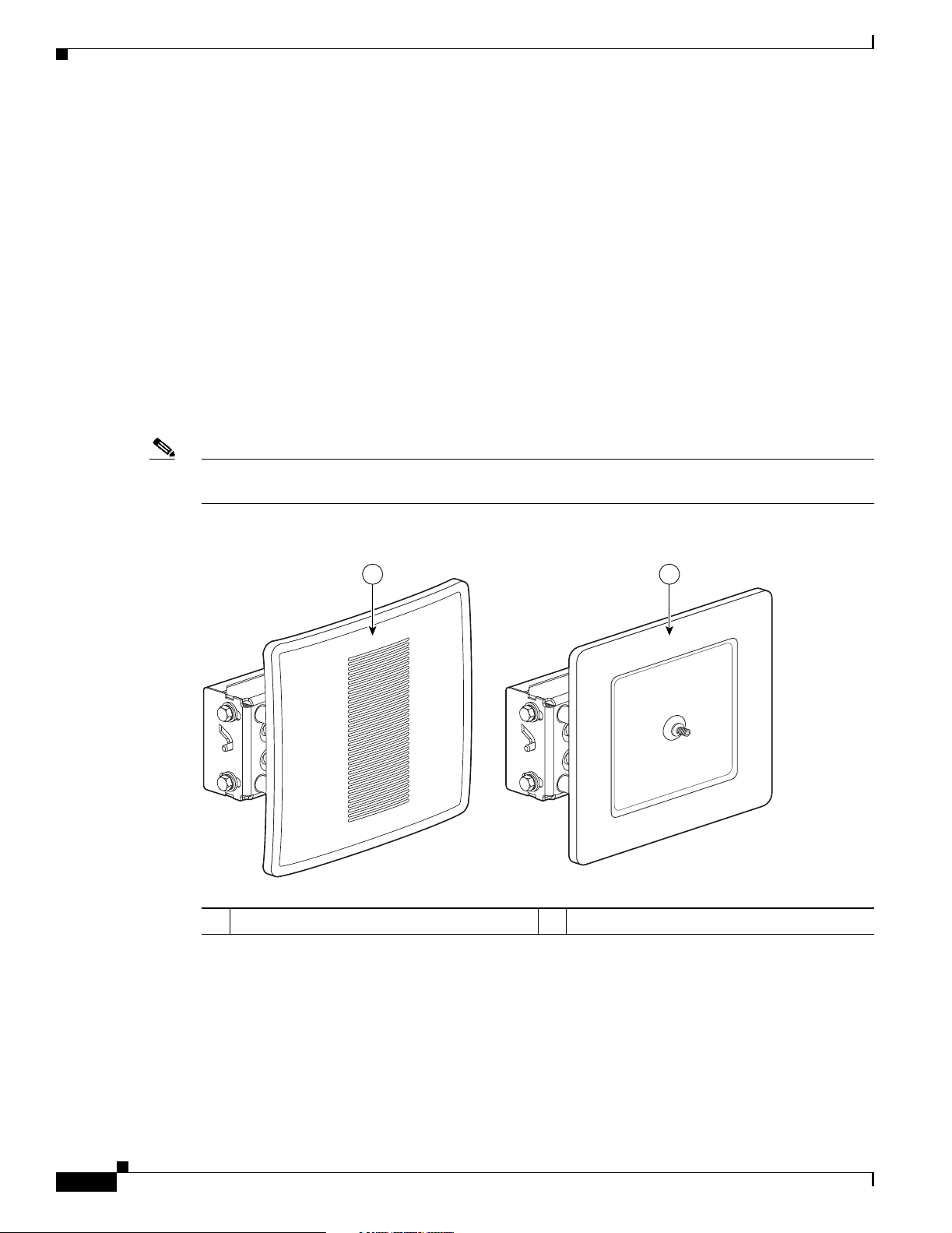
• Integrated antenna or extern al an tenna co nfigurat ions (see Figure 1-1)
• Dual-coax 100 Mbps E t hern et por ts
• Four LED indicator s on b ridge
• Inline power over dual-co ax E ther ne t c able s
• Receive Signal Strength Indic ato r (RSSI) volta ge po rt f or easy ant enna al ignm en t
• Bridge control usin g IO S com mands, I nterne t br owser, or SNMP
Note The bridge communicates only with other bridges and does not support associations with wireless client
adapters.
Chapter 1 Overview
DRAFT - CISCO CONFIDENTIAL
Power
Figure 1-1 Bridge Configurations
1 2
88795
1 Integrated antenna bridge configuration 2 External antenn a bridge configuration
1-2
The bridge receives inline power fr om the Cisco Aironet Power Injector LR (hereafter called the power
injector). Dual-coax Ethernet cables are used to provide Ethernet data and power from the power injector
to the bridge. The p ower inje c tor is an ext erna l u ni t de sign ed fo r ope ra ti on in a sh el te red environmen t,
such as inside a building. The power injector also functions as an Ethernet repeater by connecting to a
Category 5 LAN bac kbone a nd usi ng the d ual -coa xial ca ble int erfac e t o the bri dge.
Cisco Aironet 1400 Series Wireless Bridge Hardware Installation Guide
OL-4072-01
Page 17

Chapter 1 Overview
The power injector uses an external 48 VDC power module and after detecting the presence of the
bridge, injects the DC voltage into the dual coax cables to power the bridge.
Note The power injector and the power module shoul d not be plac ed in an outdoor unprotected environment.
External Antenna
The bridge is availabl e wi th a n N-t ype R F conn ec to r on t he f ron t of t he uni t ( see Figure 1-1) for an
external 5.8-GHz anten na. The supp orted externa l ante nnas conne ct to the bri dge ant enna conn ector
using the antenna’s 4.9 ft (1.5 m) long coax cable.
Note T o meet re g ulatory res trictio ns, th e ex tern al antenn a brid ge configuration and the extern al ante nna m ust
be professional insta lled.
DRAFT - CISCO CONFIDENTIAL
–
9 dBi omnidirectional external antenna with vertical polarization
–
9.5 dBi sector external antenna
–
28 dBi dish external antenna
Key Features
Integrated Antenna
The bridge is availabl e w ith a n in tegrat ed 22. 5 d Bi p at ch ar ray a nt enna . T he a nte nna i s covered w ith a
special radome cover to protect the antenna from environmental elements. When configured with the
integrated antenna, the antenna polarization is controlled by the mounting orientation of the bridge. The
bridge must be physically rotated 90 degrees to obtain either horizontal or vertical polarization. A special
polarization mark is designed into the bridge housing to indicate the polarization direction.
Dual-Coax Ethernet Ports
The bridge’s dual Ethernet ports accep ts a pair of 7 5 ohm F-type conn ectors, linking the bridge to your
100BASE-T Ethernet LAN through the power injector. The dual coax cables are used to send and receive
Ethernet data, pl us the cabl es supp ly in lin e 48 VD C power f rom th e power inj ect o r. For th e loc atio n of
the ports, refer to Figure 1-2.
Tip You can connec t the dual coax cabl e connec tors to eit her of th e br idge ’s Ethernet po rts. Th e br idge
senses the Ethernet signals an d au to matically switches internal circuitry to match the ca ble connections.
Metal Enclosure
The bridge uses a metal en closure that suppo rts outdo or operati ng environments and suppo rts an
industrial temperature operating range (refer to Bridge Speci fications, pa ge 1 -6).
OL-4072-01
Cisco Aironet 1400 Series Wireless Bridge Hardware Installation Guide
1-3
Page 18
Key Features
Indicators
Chapter 1 Overview
DRAFT - CISCO CONFIDENTIAL
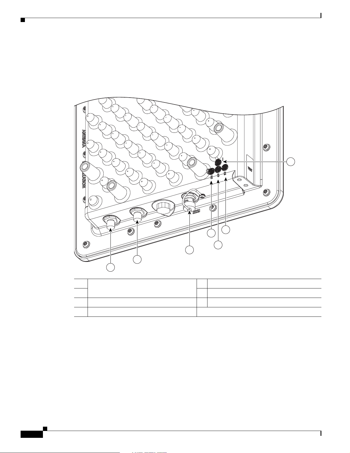
Four indicators are loc ate d on ba ck of t he hous in g to re port in stal lati on/ ali gnme nt c ond itio ns, br idge
status, radio activity, and Ethernet activity. The indicators are shown in Figure 1-2.
Figure 1-2 Bridge Connectors and Indicators
7
88777
6
4
5
3
2
1
1 Power injector dual-coax ports 5 Status LED
26Radio LED
3 RSSI voltage port 7 Install LED
4 Ethernet LED
The install indicator indicates installation mode is activated. During installation mode, the other
•
indicators provide signal strength readings used for antenna alignment.
• The radio indicator blinks green to indicate radio traffic activity. The light is normally off, but it
blinks green wh enever a packet is received or transmitted over the bridge radio lin k. This indicator
also provides signal st reng th rea ding s d uring inst al lati on mo de .
• The status indicator signals bridge association status. Blinking green indicates that the bridge is not
associated with ano ther b ridge. Steady gree n indica tes th at the brid ge is ass ociat ed with at least o ne
other bridge. This indic ator also provide s signal stre ngth read ings during i nstalla tion mod e.
1-4
Cisco Aironet 1400 Series Wireless Bridge Hardware Installation Guide
OL-4072-01
Page 19
Chapter 1 Overview
DRAFT - CISCO CONFIDENTIAL
• The Ethernet indicator signals Ethernet traffic. This indicator blinks green when a packet is received
or transmitted over the Ethernet infrastru ctu re. The in dicator is off when the Ether net link not
working or the port is shutdown. This indicator also provides signal strength readings during
installation mode.
For additional information on the LED indicators, refer to“Checking the LED Indicators” s ectio n on
page 5-2.
Receive Signal Strength Indicator Port
The bridge supports a radio signal strength indicator (RSSI) port for use in antenna alignment. The RSSI
port produces a DC voltage proportional to the strength of the received radio signal. The highest voltage
indicates the best antenna alignment position. The RSSI port is a male BNC connector located on the
bottom of the br id ge ho using (se e Figure 1-2).
Note The RSSI port requires the use of a voltmeter and a cable with a female BNC connector.
Network Configuration Examples
Network Configuration Examples
This section desc ribe s th e brid ge’s role in three comm on wirele ss network co nfigurations.
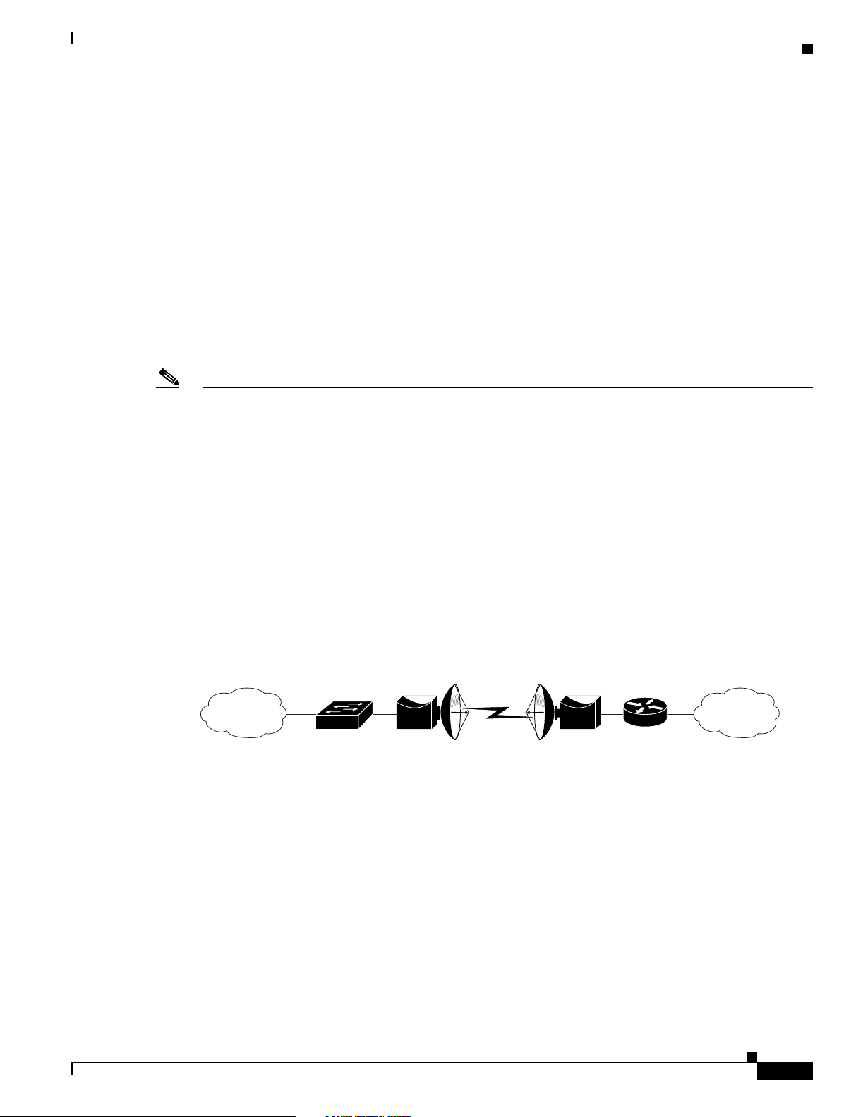
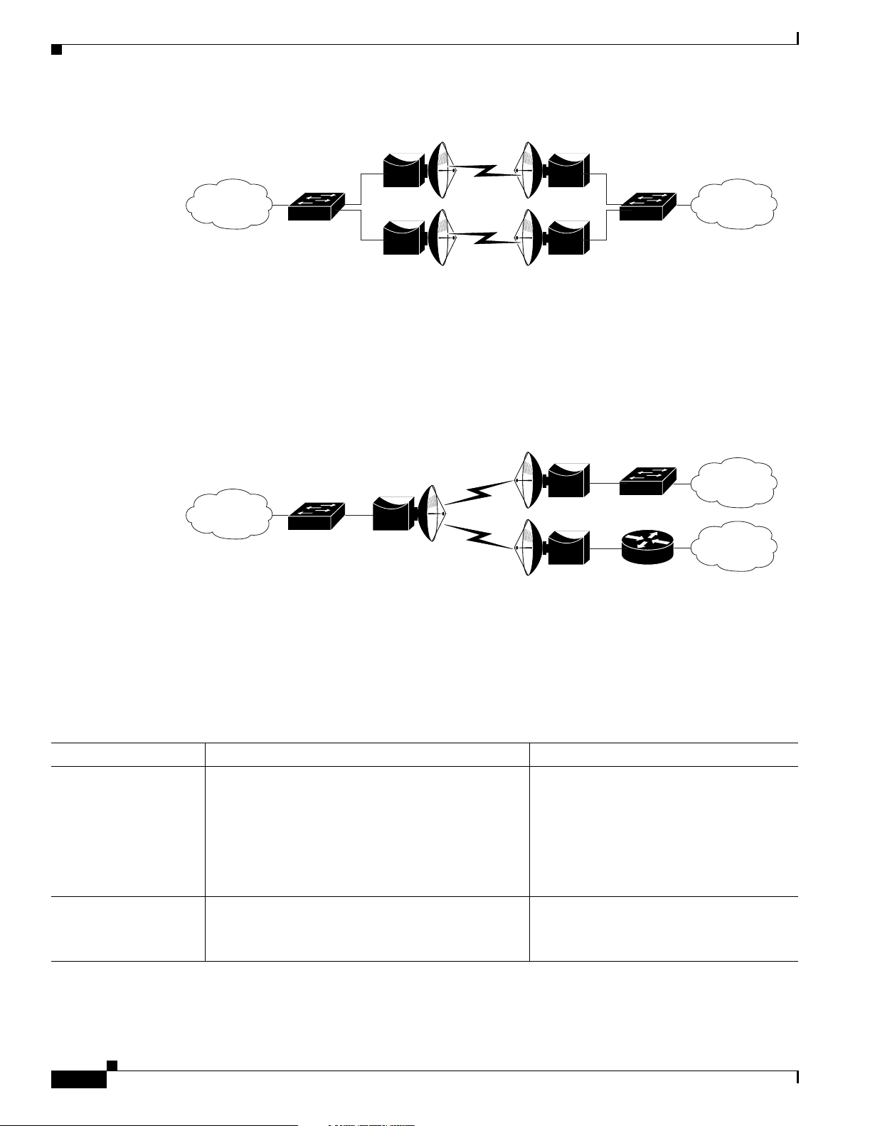
Point-to-Point Configuration
In a point-to-poi nt co nfigurati on, t wo br idge s are used t o inte rc onnec t t wo re mo te LAN net works
together using a wireless c om munica tion l ink ( see Figu re 1-3). The brid ge conne ct ed t o th e ma in LAN
network is classified as a root bridge and the other bridge is classified as a repeater bridge.
Figure 1-3 Point-to-Point Bridge Configuration
Bridge Bridge
Port Aggregation or Redundancy Configuration
The port aggregation o r re dunda ncy configu ratio n ( Figur e 1-4) is used to provide increased bandw idth
or backup redunda ncy com mu nicat ions bet wee n two LA Ns. Po rt a gg regation or i ncre ased band widt h
occurs when b oth wirele ss links are us ed to simu ltaneous ly pass Ethe rnet traf fi c. Backup com municatio n
redundancy can be achieved with this configuration when one wi reless bri dge link is use d only if the
other wireless bridge link fails.
88833
OL-4072-01
Cisco Aironet 1400 Series Wireless Bridge Hardware Installation Guide
1-5
Page 20
Bridge Specifications
Chapter 1 Overview
DRAFT - CISCO CONFIDENTIAL
Figure 1-4 Port Aggregation or Redundancy Bridge Configuration
Bridge Bridge
Point-to-Multipoint Configuration
The point-to-mult ipoint co nfiguration (Figu re 1 -5) is used to interconnect the main LAN network to
multiple remote LAN networks.
Figure 1-5 Point-to-Multipoint Bridge Configuration
Bridge Specifications
Bridge Bridge
Bridge
Bridge
Bridge
88834
88835
The bridge, power injector, and power module specifications are list ed in Table 1-1.
Table 1-1 Bridge, Power Injector, and Power Module Specifications
Category Bridge Power Injector
Size Integrated antenna configuration:
11.6 in. W x 11 .6 in. H x 3. 6 in. D
29.46 cm W x 29.46 cm H x 9.14 cm D
External ant enn a co nfigur ation:
11.4 in. W x 11.4 in. H 4.2 in. D
28.96 cm W x 28. 96 cm H 10 .67 c m D
Indicators Four indicators on the back panel: Installation and
Alignment Mode, Ethernet traffic, bridge status, and
radio traffic
Cisco Aironet 1400 Series Wireless Bridge Hardware Installation Guide
Power injector:
6.25 in. W x 6.38 in. H x 1.31 in. D
15.88 cm W x 16 .21 cm H x 3.33 cm D
Power module:
6.0 in. W x 2.75 i n. H x 1.75 in . D
15.24 cm W x 6.99 cm H x 4.45 cm D
Three indicators on the front panel: Uplink
activity, injector status, Ethernet activity
One indicator on the side pane l: Power
1-6
OL-4072-01
Page 21

Chapter 1 Overview
Bridge Specifications
DRAFT - CISCO CONFIDENTIAL
Table 1-1 Bridge, Power Injector, and Power Module Specifications (continued)
Category Bridge Power Injector
Connectors Bottom panel (left to right): Ethernet port1 and port 2
(two F-type con ne ctor s), RSSI p ort (m al e BN C
connector)
Front Panel (external antenna co nfigurati on):
antenna Type N connector
Operating Temperature –22 to 131
Cold Start Temperature -22
Warm -up t ime
o
15 minutes after cold start na
o
F (–30 to 55oC) 32 to 122oF (0 to 50oC)
F (-30oC) na
(for full performance)
o
Non-Operational
–40 to 185
F (–40 to 85oC) -40 to 158oF (-40 to 70oC)
Temperature
Operational Altitude 6,562 ft (2000 m) 6,562 ft (2000 m)
Non-Operational
16,000 ft (4877 m) 16,000 ft (4877 m)
Altitude
Humidity 0 to 100% (condensi ng ) 0 to 90% (non-condens in g)
2
Operational Vibration 0.001 G
Non-Operational
0.01 G
/Hz from 5-100 Hz 0.001 G2/Hz from 5-100 Hz
2
/Hz from 5-10 0 Hz 0.01 G2/Hz from 5-100 Hz
Vibration
Environmental Testing
Compliance
Integrated antenna configuration:
The enclosure has been successfully tested for
protection against the ingress of particulate
matter and fluids in compliance with a NEMA
Type 4 (I P56) e nc losur e ra ti ng.
Side panel (left to right): 48VDC power
connector, two coaxial uplink F-type
connectors, and Ether net RJ-4 5 connect or
for 100BASE-T Ethernet
na
External ant enn a co nfigur ation:
The enclosure ha s been succes sfully tested and is
in compliance with a NEMA Type 4 (IP56)
enclosure rating.
Weight Integrated antenna configuration:
11 lbs (4.99 kg)
Power injector—1.4 lbs (0.6 Kg)
Power Module—TBD
External ant enn a co nfigur ation:
10 lbs (4.54 kg)
Input Voltage 48 VDC nominal (s upplie d by Ethe rnet dua l-c oax
cables)
Power Consumption 41 W (typical)
Power injector—48 VDC nominal
Power module—100-240 VAC
TBD W (maximum)
TBD W (maximum)
Transmit Power 24, 23, 22, 2 1, 18, 1 5, 12 dB m na
Frequency UNII 3—5.7 25 to 5.825 G Hz
na
(Depending on the regulatory do main)
Wireless modulation Coded Orthogonal Frequency Division Multiplexing
na
(COFDM)
Cisco Aironet 1400 Series Wireless Bridge Hardware Installation Guide
OL-4072-01
1-7
Page 22

Bridge Specifications
DRAFT - CISCO CONFIDENTIAL
Table 1-1 Bridge, Power Injector, and Power Module Specifications (continued)
Category Bridge Power Injector
Subcarrier mod ulation BPSK (6 Mbps and 9 Mb ps)
QPSK (12 Mbps and 18 Mbps)
16-QAM (24 Mbps and 36 Mb ps)
64-QAM (48 Mbps and 54 Mb ps)
Data rates 6, 9, 12, 18, 24, 36, 48, and 54 M bps na
Non-overlapping
4na
channels
Antenna Integrated antenna —22.5 dBi patch array
External antennas:
9 dBi omnidirect iona l
9.5 dBi sector
28 dBi dish
Range (typical) Point-to-Point orientation
• Two 22.5 dBi integrated antennas:
–
7.8 miles at 54 Mbps
na
na
na
Chapter 1 Overview
–
15.5 miles at 6 Mbps
• Two 28 d Bi dish a ntenna s:
–
11.9 miles at 54 Mbps
–
23.4 miles at 6 Mbps
Point-to-Multipoint orientation
• 9 dBi omnidirectional antenna at the root
location and 22.5 dBi integrated antenna at the
non-root locatio n:
–
2.0 miles at 54 Mbps
–
8.3 miles at 6 Mbps
• 9.5 dBi sector an te nna a t t he roo t loc ation a nd
22.5 dBi integrated antenna at the non-root
location:
–
2.2 miles at 54 Mbps
–
8.5 miles at 6 Mbps
• 9 dBi omnidirectional antenna at the root
location and 28 dBi dish antenna at the non- root
location:
–
3.0 miles at 54 Mbps
1-8
–
9.8 miles at 6 Mbps
• 9.5 dBi sector an te nna a t t he roo t loc ation a nd
28 dBi dish antenna at the non -root locati on:
–
3.4 miles at 54 Mbps
–
10.2 miles at 6 Mbps
Cisco Aironet 1400 Series Wireless Bridge Hardware Installation Guide
OL-4072-01
Page 23

Chapter 1 Overview
DRAFT - CISCO CONFIDENTIAL
Table 1-1 Bridge, Power Injector, and Power Module Specifications (continued)
Category Bridge Power Injector
Safety Bridge, power injector, and power module:
UL 60950
CSA C22.2 No. 60 950
IEC 60950
EN 60950
Note The power injector and th e power mod ule mu st be u sed i n an i n door environment.
Electromagnetic
Compatibility (EMC)
Radio Type Approvals Bridge radio:
RF Exposure Bridge antenn a:
Bridge, power inje ctor, and p ower modu le:
FCC Part 15.107 and 15.109 C lass B
ICES-003 Class B (Canada)
EN 55022 Class B
EN 55024
na
FCC Part 15.207, 15. 407 , and15. 20 9 C lass B
ICES-003 Class B (Canada)
Canada DGTP-010
FCC Bulletin OET-65C
Industry Canada RSS-102, RSP100 , and
RSS 210 Issue 5
na
Bridge Specifications
AIR-ANT58G28SDA-NAironet
AIR-ANT58G10SSA-NAironet
AIR-ANT58G9VOA-NAironet
OL-4072-01
Cisco Aironet 1400 Series Wireless Bridge Hardware Installation Guide
1-9
Page 24

Bridge Specifications
Chapter 1 Overview
DRAFT - CISCO CONFIDENTIAL
1-10
Cisco Aironet 1400 Series Wireless Bridge Hardware Installation Guide
OL-4072-01
Page 25

DRAFT - CISCO CONFIDENTIAL
CHAPTER
2
Installation Overview
This chapter provides warnings, safety information, and information needed before you begin the
installation of your bridge system. This chapter includes the following sections:
• Warnings, pag e 2-2
• Safety Informat ion, p ag e 2-3
• Unpacking the Bridge, page 2-5
• Before Beginning the I nsta llat ion, pag e 2-6
• Installation Summary, page 2-8
OL-4072-01
Cisco Aironet 1400 Series Wireless Bridge Hardware Installation Guide
2-1
Page 26
Warnings
Warnings
Chapter 2 Installation Overview
DRAFT - CISCO CONFIDENTIAL
Translated versions of the following safety warnings are provided in Appendix A , “Translated Safe ty
Warnings. ”
Warning
Warning
Warning
Warning
Warning
This warning symbol means danger. You are in a situation that could cause bodily injury. Before
you work on any equipment, be aware of the hazards involved with electrical circuitry and be
familiar with standard practices for preventing accidents. (To see translations of the warnings
that appear in this publication, refer to the appendix “Translated Safety Warnings.”)
Only trained and qualified personnel should be allowed to install, replace, or service this equipment.
Do not locate the antenna near overhead power lines or other electric light or power circuits, or
where it can come into contact with such circuits. When installing the antenna, take extreme care
not to come into contact with such circuits, as they may cause serious injury or death. For proper
installation and grounding of the antenna, please refer to national and local codes (e.g. U.S.:NFPA 70,
National Electrical Code, Article 810, in Canada: Canadian Electrical Code, Section 54).
This product relies on the building’s installation for short-circuit (overcurrent) protection. Ensure that
the protective device is rated not greater than:
120V ac, 15A U.S. (240Vac, 10A International)
Never defeat the ground conductor or operate the equipment in the absence of a suitably installed
ground conductor. Contact the appropriate electrical inspection authority or an electrician if you are
uncertain that suitable grounding is available.
2-2
Warning
Warning
Warning
Warning
Cisco Aironet 1400 Series Wireless Bridge Hardware Installation Guide
Read the installation instructions before you connect the system to its power source.
Do not work on the system or connect or disconnect cables during periods of lightning activity.
Do not operate your wireless network device near unshielded blasting caps or in an explosive
environment unless the device has been modified to be especially qualified for such use.
Industry standards relating to radio frequency (RF) exposure limits for this product require that the
antennas should be positioned no less than 6.6 ft (2 m) from your body or nearby persons.
OL-4072-01
Page 27

Chapter 2 Installation Overview
Safety Information
DRAFT - CISCO CONFIDENTIAL
Warning
This unit is intended for installation in restricted access areas. A restricted access area can be
accessed only through the use of a special tool, lock and key, or other means of security.
Safety Information
Follow the guidelines in this section to ensure proper operation and safe use of the bridge.
FCC Safety Compliance Statement
The FCC, with its action in ET Doc ket 96-8, has adop ted a safe ty standard for human exposur e to RF
electromagnetic energy emitted by FCC-certified equipment. When used with approved Cisco Aironet
antennas, Cisco Aironet products meet the uncontrolled environmental limits found in OET-65 and ANSI
C95.1, 1991. Proper operation of this radio device according to the instructions in this publication results
in user exposure substantially below the FCC recommended limits.
Safety Precautions
Warning
Do not locate the antenna near overhead power lines or other electric light or power circuits, or
where it can come into contact with such circuits. When installing the antenna, take extreme care
not to come into contact with such circuits, as they may cause serious injury or death. For proper
installation and grounding of the antenna, please refer to national and local codes (e.g. U.S.:NFPA 70,
National Electrical Code, Article 810, in Canada: Canadian Electrical Code, Section 54).
Each year hundreds of people are killed or injured when attempting to install an antenna. In many of
these cases, the victim was aware of the danger of electrocution, but did not take adequate steps to avoid
the hazard.
For your safety, and to help you achieve a good installation, please read and follow these safety
precautions. They may save your life!
1. If you are installing an antenna for the first time, for your own safety as wel l as other s, seek
professional assistance.
2. Select your installation site with safety, as well as performance in mind. Remember: electric power
lines and phone lines look alike. For your safety, assume that any overhead line can kill you.
3. Call your electric power company . Tell them your plans and ask them to come look at your proposed
installation. This is a small inconvenience considering your life is at stake.
4. Plan your installa tio n ca re fully a nd co mp let ely befo re you begin. Suc cessf ul r aisi ng of a m ast or
tower is largely a matter of coordination. Each perso n should be assign ed to a spec ific task, and
should know what to do and when to do it. One person should be in charge of the operation to issue
instructions and watc h for sign s o f troub le.
5. When installing your antenna, remember:
a. Do not use a metal ladder.
b. Do not work on a we t or wi ndy da y.
OL-4072-01
Cisco Aironet 1400 Series Wireless Bridge Hardware Installation Guide
2-3
Page 28

Safety Information
DRAFT - CISCO CONFIDENTIAL
c. Do dress properly—shoes with rubber soles and heels, rubber gloves, long sleeved shirt or
jacket.
6. If the assembly starts to drop, get away from it and let it fall. Remember, the antenna, mast, cable,
and metal guy wires are all excellent conductors of electrical current. Even the slightest touch of any
of these parts to a power line complete an electrical path through the antenna and the installer: you!
7. If any part of the antenna syste m should com e in cont act wit h a power line, don ’t touch it or try to
remove it yourself. Call your local power company. They will remove it safely.
If an accident should occur with the power lines call for qualified emergency help immediately.
Typical Bridge Installation Components
The bridge is designed to be installed in an outdoor environment, typically, on a tower or a tall building.
A typical bridge installation diagram is shown in Figure 2-1.
Figure 2-1 Typical Bridge Installation Diagram
Chapter 2 Installation Overview
Building
entrance
Indoor
CAT5
Ethernet
LAN network
Note 1) Ground wires must comply with Sections 810 and 820 of the National Electrical Code and Section 54
cable
Power
injector
Power
module
Dual-coax
cables
Grounding
block
Outdoor
Dual-coax
cables
Ground
(see note 1)
Integrated
or
external antenna
Bridge
of the Canadian Electrical Code.
Caution To ensure correct installation and grounding, install the bridge in compliance with your local and
national electrical codes: National Fire Protection Association (NFPA) 70, National Electrical Code
(U.S.); Canadian Ele ctrical C ode, Par t I, CSA 22. 1 (Canada) ; and if loca l or natio nal electric al codes ar e
not available, refer to IEC 364, Part 1 through 7 (other countries) .
88836
2-4
Cisco Aironet 1400 Series Wireless Bridge Hardware Installation Guide
OL-4072-01
Page 29

Chapter 2 Installation Overview
DRAFT - CISCO CONFIDENTIAL
Installation Guidelines
Because the bridge is a radio device, it is susceptible to common causes of interference that can reduce
throughput and range. Follow these basi c guideli nes to ensure t he best possible performa nce:
• Install the bridge in an area where structures, trees, or hills do not obstruct radio signals to and from
the bridge.
• Install the bridge at a height sufficient to provide line-of-sight orientations.
Site Surveys
Because of differen ces i n comp one nt co nfigurat ion, p lac em ent , an d p hysi cal environmen t, every
network application is a unique installation. Before installing multiple bridges, you should perform a site
survey to determine the optimum utilization of networking components and to maximize range,
coverage, and network p erfor ma nce.
Consider the following operating and environmental conditions when performing a site survey:
• Data rates—Sensitivity and range are inversely proportional to data bit rate s. The maxi mum radi o
range is achieved at the lowest workable data rate. A decrease in receiver sensitivity occurs as the
radio data increases.
Installation Guidelines
• Antenna type and p lacement—Proper antenna configuration is a critical factor in maximizing radio
range. As a general rul e, ra nge in cr ease s in p rop ortio n to an te nna he ig ht. However , d o not pl a ce the
antenna higher than necessary, because the extra height also increases potential interference from
other unlicensed radio systems.
• Physical environment—C lear or open areas provide better radio range than closed or filled areas.
• Obstructions—Physical obstructions such as buildings, trees, or hills can hinder performance of
wireless devices. Avoid loca ting the devices in a location where there is an obstruction between the
sending and receiving ante nnas.
Unpacking the Bridge
Follow these steps to unpack the bridge:
Step 1 Open the shipping container and carefully remove the contents.
Step 2 Return all pack i ng ma ter ials t o t he sh ippi ng conta ine r and save it.
Step 3 Ensure that all items listed in the “Package Contents” section are included in the s h ipment. Check each
item for damage. If any item is damage d or missin g, notif y your autho rized Cisc o sales repre sentat ive.
OL-4072-01
Cisco Aironet 1400 Series Wireless Bridge Hardware Installation Guide
2-5
Page 30

Before Beginning the Installation
Package Contents
Each bridge pa ck ag e co nt ain s the f ol lowing ite ms :
• Bridge unit
• Power injector unit (with mounting screws and wall anchors)
• Power module and AC power cord (wi th m oun ting s cr ews and wa ll a nc hors)
• Two dual-c oa x ca bles [2 0 ft ( 6.1 m) an d 5 0 f t ( 15.2 m )]
• Mounting kit and hardware
• Grounding Block and mounting sc rews
• Ground lug for the bridge with screws
• Weatherpr oofing kit (consisting of Coa x Seal and anti -corrosio n gel)
Chapter 2 Installation Overview
DRAFT - CISCO CONFIDENTIAL
–
Multi-function m oun t (c ons isting o f two br idge b rackets an d one t ower or ma st b racke t)
–
Two tower clamps (U-bolts) with four nuts, washers, and lock washers
–
Four bolts and washers for securing the bri dge brackets to th e tower or mast bracket
–
Four bolts, washers, and l ock washer s f or secu ring th e b ridge bra c kets to the br idge
• Quick Start Guide: C isco A ironet 1400 Seri es Wireless Bridge
• Cisco Aironet 1400 Series Wireless Bridge Mounting Instructions
• Cisco product registration an d Cisco docum entati on feedba ck card s
Before Beginning the Installation
Before you begin the installation process, please carefully review the following list of figures to become
familiar with the system components, connectors, indicators, cables, system interconnection, and
grounding:
• Bridge block diagram (Figu re 2 -1)
• Bridge layout (Figu re 2-2)
• Power injector layout (Figure 2-3)
• Power module (Figure 2-4)
• Grounding block ( Figure 2-5)
2-6
Cisco Aironet 1400 Series Wireless Bridge Hardware Installation Guide
OL-4072-01
Page 31

Chapter 2 Installation Overview
Figure 2-2 Bridge Layout and Connectors
1
Before Beginning the Installation
DRAFT - CISCO CONFIDENTIAL
1
88796
4 3
5
6
2
1 Bridge mounting brackets 4
2 Bridge LED indicators 5 Power injector dual-coax ports (F-type
3 RSSI voltage port (Female BNC connector) 6
Figure 2-3 Power Injector Indicators and Connectors
connectors)
6
1
3
2
5
4
88809
OL-4072-01
1 Power jack (+ 48 VD C) 4 Mode button
2 Power LED indicator 5 Ethernet port (RJ45 co nnecto r)
3 Power injector dual-coax ports (F-Type connectors) 6 Indicator LEDs
Cisco Aironet 1400 Series Wireless Bridge Hardware Installation Guide
2-7
Page 32

Installation Summary
Chapter 2 Installation Overview
DRAFT - CISCO CONFIDENTIAL
Figure 2-4 Power Module
3
2
1
88829
1 48 VDC power output cable 2 Power module
3 AC powe r cord
Figure 2-5 Grounding Block
1 2 3
1 and 2 F-type coaxial connectors 3 Ground wire lug
Installation Summary
During the inst allat ion o f th e brid ge, y ou w ill pe rfo rm t he f ol lowing ope rat ions:
• Connect a user sup plie d CAT5 Ethernet cable from your wire d L AN netwo rk to the power in ject or.
• Connect the dual-coax Ethernet cables between the power injector and the grounding block
Tip You can connec t the dual coax cable co nnecto rs to either of the gr ounding bl ock conne cto rs or
the power injector’s Ethernet po rt s. T he br i dge se nses th e Et her ne t signa ls a nd aut omat ical ly
switches internal circuitry to match the cable connections.
• Connect a ground wi re t o the grou ndi ng blo ck.
• Mount the bridge to the external tower or mast. For additional information, refer to the Cisco Aironet
Series 1400 Wireless Bridge Mou nting Instru ctions t hat sh ip ped w ith you r bridg e.
• Connect a ground w ire to the br idge (use th e brid ge gr oun d lu g)
88830
2-8
Cisco Aironet 1400 Series Wireless Bridge Hardware Installation Guide
OL-4072-01
Page 33

Chapter 2 Installation Overview
• Connect the dual-coa x Ethern et cabl es to the grounding block and t o the brid ge.
Tip You can connec t the dual coax cable co nnecto rs to either of the gr ounding bl ock conne cto rs or
• Connect the AC power cord to the 48 VDC power module.
Tip The root bridge s hould be positioned and p owered up bef ore the no n-r oot bridg e.
• Connect the power module to the power injector and plug the AC cord into an AC power receptacle.
• Align the bridge antenna . For addit ional informatio n, refer to the Cisco Aironet 1400 Series W ireless
Bridge Mounting Instructions that shipped with your bridge.
• Configure basic settings (refer to Chapter 4, “Configuring the Bridge for the First Time”).
• Seal all external connectors with special weather sealing material.
• Configure security and other bridge options. For additional information, refer to the Cisco Aironet
1400 Series Wireless Bridge Software Configuration Guide.
Installation Summary
DRAFT - CISCO CONFIDENTIAL
the bridge’s Ethernet ports. The bridge senses the Ethernet signals and automatically switches
internal circuitry to match the cable connections.
OL-4072-01
Cisco Aironet 1400 Series Wireless Bridge Hardware Installation Guide
2-9
Page 34

Installation Summary
Chapter 2 Installation Overview
DRAFT - CISCO CONFIDENTIAL
2-10
Cisco Aironet 1400 Series Wireless Bridge Hardware Installation Guide
OL-4072-01
Page 35

DRAFT - CISCO CONFIDENTIAL
CHAPTER
3
Mounting and Alignment Overview
This chapter provides an overview of bridge mounting and antenna alignment. The following sections
are included in this ch apt er:
• Mounting the Bridg e, pa ge 3-2
• Mounting Hardware, page 3 -2
• Bridge LED Indica tors, page 3-3
• Aligning the Ante nna U sing L ED Ind icat ions, page 3 -5
• Aligning the Antenna Us ing the R SSI Voltage, page 3-6
OL-4072-01
Cisco Aironet 1400 Series Wireless Bridge Hardware Installation Guide
3-1
Page 36

Mounting the Bridge
DRAFT - CISCO CONFIDENTIAL
Mounting the Bridge
Typically, the bridge is installed on a rooftop, mast, tower, wall, or a suitable flat surface. Each of these
installation methods requires different approaches to the installation proc ess. T his docume n t provides a
mounting overview, refer to the Cisco Air onet 1400 Series W ir eless Bridge Installation Instructions that
shipped with your br idge f or de tail ed mou nting i nstruct ions.
The bridge is available in two configurations
• Integrated antenna bridge (with 22.5 dBi directional antenna)
• External antenna bridge (with antenna connector for use with an external antenna)
Note T o meet re g ulatory res trictio ns, th e ex ternal an tenn a bridg e configuration and the external an tenn a must
be professional insta lled.
Personnel installing the bridge must understand wireless bridging techniques, antenna alignment and
adjustment, and ground ing method s. The in tegrated ante nna co nfiguration c an be instal led by an
experienced IT professi onal.
Chapter 3 Mounting and Alignment Overview
Mounting Hardware
The bridge is shipped with t he foll owing mounting ha rdware:
• Multi-function m oun t (c ons isti ng o f t wo br idge b rackets , a nd on e ma st b ra cket)
• Fastener hardware (consisting of nu ts, bolts, washer s, and U- bolts)
Multi-function Mount
The multi-function mo unt provides a metho d for mounti ng the bridg e on a mast, tower, or an optional
roof mast mount. The multi-fun ction mount p ermits e asy azimuth a nd elevation adjustments for antenna
alignment purpose s. The basi c mounti ng proced ure is shown below:
• Mount the two bridg e br ac kets to t he b ridge with the sup port pin s fac ing the side s of t he br idge .
• Mount the mast bracket to the tower or mast using the suppli ed U-bolts .
• Suspend the bridge on the mast bra cket usi n g th e bri d ge br ac ket su pport p ins.
• Secure the bridge b ra ckets t o th e mast bra cket using the su pplie d n uts, bo lts, a nd washers (ha nd
tighten).
• Align the bridge and tighten the nuts and bolts.
Bridge Brackets
3-2
The two bridge bra cket s moun t on t he b ac k si de of the b ridg e housi ng. E ach br ac ket moun t s on two
screw posts on opposite e nds of th e uni t. Th e s uppo rt p in on t he br idge br acket m ust be fac ing the side
of the unit. The se su ppo rt p ins are u sed to susp en d th e bridg e in th e not ch es o n th e ma st m oun t ing
bracket until you secure the mounting bolts.
Cisco Aironet 1400 Series Wireless Bridge Hardware Installation Guide
OL-4072-01
Page 37

Chapter 3 Mounting and Alignment Overview
The bridge brackets must be positioned to obtain the correct antenna polarization that matches the
remote antenna. The bridge housing contains an antenna polarization mark consisting of an arrow on the
side of the housing. When the bridge is positioned so that the arrow is pointing up, the bridge antenna is
vertically polarized. For horizontal polarization, the arrow should be pointing from left to right. All
bridges must use the same antenna polariz ation fo r best operat ion.
Mast Bracket
The mast bracket attaches to a mast or tower support and is used to secure the bridge.The procedure for
attaching the mo unti ng br acket to th e su ppo rt d ep en ds o n the pi pe d iam et er, as shown in Table 3-1.
Table 3-1 Mast Bracket Attachment Methods
Mast Type Mast Diameter Mast Attachment Method
Roof mount,
small mast, or
tower
Large mast 2. 5 to 4 .5 i nche s
DRAFT - CISCO CONFIDENTIAL
1.25 to 2.5 inches
(30.5 to 63.5 mm)
(63.5 to115 mm)
Attach the pipe inside the mountin g bracket, between the
bracket and bridge.
Attach the pipe outside the mounting bracket , away from
the bridge.
Bridge LED Indicators
Bridge LED Indicators
When you power up the bridge for the first time, it starts in a special installation mode. The LEDs
indicate the star tup s tat us, op er ating m ode , a ssoc iation st atu s, an d rec eived signal st ren gth. T his
information simplifies the proc ess of activating the link and positi oning the an tenna fr om the bridge
mounting location.
The LEDs are mou nt ed on t he bac k of the h ousin g, ne ar t he co nne cto rs (see Figure 1).
OL-4072-01
Cisco Aironet 1400 Series Wireless Bridge Hardware Installation Guide
3-3
Page 38

Bridge LED Indicators
Chapter 3 Mounting and Alignment Overview
DRAFT - CISCO CONFIDENTIAL
Figure 1 LED and Connector Locations
4
88818
3
1
2
1 Ethernet LED 3 Radio LED
2 Status LED 4 Install LED
When the bridge is initially powered-up, installation mode is activated and the bridge attempts to
associate to a root bridge for 60 seconds. If it is unable to associate with a root bridge, it automatically
assumes the root bridge role. The Install LED provides bridge association status during installation mode
as shown in Table 3-2.
Table 3-2 Install LED Association Status
Install LED State Bridge State
Off Self test Startup
Amber blink Non-root, searchi ng Not associated ( non -root m ode). T he
bridge attempts to associate with a root
1
bridge for 30 sec ond s
.
Amber solid Non-root, associated Asso ciated (n on-root mo de)
Green blink Root, searching Not associated ( roo t mo de). T he br i dge
attempts to a ssociat e w it h a non- ro ot
bridge indefinitely.
Green solid Root, associated Associated (root mode)
1. Pre-configured bridges search indefinitely.
3-4
Cisco Aironet 1400 Series Wireless Bridge Hardware Installation Guide
OL-4072-01
Page 39

Chapter 3 Mounting and Alignment Overview
DRAFT - CISCO CONFIDENTIAL
You use the Install LED to determine when the bridge successfully associates with a remote bridge and
to verify its mode of operation. A fter associat ion, the other three LEDs indicat e signal stre ngth (see
Table 3-3).
The startup and associa tion sequ ence d epends on th e bridge configuratio n, which ca n be one of the
following types:
• Default—The bridge attemp ts to ass oci ate with a ro ot br idge fo r 30 sec onds . If it does not asso ci ate
with a root bridge, it then attempts to associate with a non-root bridge.
• Pre-configured—The bridge attempts to associate with a remote bridge in the configured mode,
either root or non-root. Because there are no time-outs, it is easier to align the antenna.
Aligning the Antenna Using LED Indications
You can align the integrated antenna using LEDs after the bridge successfully associates with a remote
bridge. In the installation mode before association to another bridge, the Install LED blinks amber. If the
bridge associates to a root bridg e, the I nstall LE D turn s stead y amber. If the bridge do es not assoc iate to
a root bridge in th e first 30 seco nds, the Inst al l LE D b lin ks g reen to i ndic ate b ea cons ar e be ing
transmitted and the bridge is waiting for another non-root bridge to associate. After association, the
Install LED turns into steady green and the Ethernet, status, and radio LEDs then display signal strength
as shown in Table 3-3).
Aligning the Antenna Using LED Indications
Note For the signal leve l (dBm), a smaller number represents a stronger signal because the signal le vel is gi ven
as a negative value.
Note Each time you move the antenna, you must wa it approximately 20 seconds before the LED patterns are
valid.
Table 3-3 LED Installation Mode Signal Strength Display
Signal Level (dBm) Ethernet LED Status LED Radio LED
>-44 On On On
-47 to -44 Fast blink
-50 to -47 Me dium blin k
-53 to -50 Slow blink
1
3
On On
2
On On
On On
-54 to -53 Off On On
-57 to -54 O ff Fast blink
1
-60 to -57 O ff Medium blink
-63 to -60 Off Slow blink
3
On
2
On
On
-66 to -63 O ff Off On
-69 to -66 Off Off Fast blink
-72 to -69 Off Off Medium blink
-75 to -72 Off Off Slow blink
1
2
3
< -75 Off Off Off
OL-4072-01
Cisco Aironet 1400 Series Wireless Bridge Hardware Installation Guide
3-5
Page 40

Chapter 3 Mounting and Alignment Overview
Aligning the Antenna Using the RSSI Voltage
DRAFT - CISCO CONFIDENTIAL
1. Slow blinking rate of 1 Hz/sec.
2. Medium blin kin g r ate of 2 Hz /se c.
3. Fast blinking rate of 4 Hz/sec.
When using LEDs to maximize the signal, you adjust the antenna until as many LEDs as possible are
turned-on and t he r est ar e blinki ng as fa st a s p ossibl e.
Aligning the Antenna Using the RSSI Voltage
The RSSI port outputs a DC voltage that is proportional to the received signal level. The RSSI voltage
is available whenever a signal is present, regardless of the bridge mode (installation or normal),
association status, or pre-configuration role setting. The RSSI voltage provides an instantaneous reading
as you move the antenna. The RSSI port is a female BNC connector on the bridge housing (see Figure 1 ).
The RSSI voltage increases linearly with signal level as shown in Table 4.
Note A larger RSSI voltage reading indicates a stronger signal.
Table 4 RSSI Voltage Levels
Nominal Signal Level (dBm) RSSI Reading (volts)
-20 or greater 2.70
-30 2.31
-40 1.93
-50 1.54
-60 1.16
-70 0.77
-80 0.39
-90 or less 0.00
The voltage varies from 0 to 2.7 volts for signals between -90 and -20 dBm, respectively. The accuracy
over temperature and co mp onent variati ons is ± 4dB. To obtain RSSI readi ngs, you ca n use a ny
convenient voltmeter connec ted to th e RSS I port u sing a cabl e wit h a male BN C con necto r.
3-6
Cisco Aironet 1400 Series Wireless Bridge Hardware Installation Guide
OL-4072-01
Page 41

DRAFT - CISCO CONFIDENTIAL
CHAPTER
4
Configuring the Bridge for the First Time
This chapter describes how to configure basic settings on your bridge for the first time. The contents of
this chapter are similar to the instructio ns in the quick start guid e that shipped with your bri dge. You can
configure all the settings described in this chapter using the CLI, but it might be simplest to browse to
the bridge’s web-browser interface to complete the initial configuration and then use the CLI to enter
additional settings for a more detailed configuration.
This chapter contains these sections:
• Before You Start, page 4-2
• Obtaining and Assigning an IP Address, page 4-3
• Connecting to the Bridge Locally, page 4-3
• Assigning Basic Settings , pa ge 4- 4
• What To Do Next, page 4-8
• Using the IP Setup Utility, page 4-9
• Assigning an IP Address Using the CLI, page 4-12
• Using a Telnet Session to Access the CLI, page 4-12
OL-4072-01
Cisco Aironet 1400 Series Wireless Bridge Hardware Installation Guide
4-1
Page 42

Before You Start
DRAFT - CISCO CONFIDENTIAL
Before You Start
Before you install the bridge, make sure you are using a computer connected to the same network as the
bridge, and obt ain the f oll owing infor ma tion:
• The following inform ati on from y our net work sy st em a dm ini stra tor:
–
A system name
–
The case-sensitive wireless service set identifier (SSID) for your radio network
–
If not connected to a DHCP server, a unique IP address for your bridge (such as 172.17.255.115)
–
If the bridge is not on the same subnet as your PC, a default gateway address and subnet mask
–
A Simple Network Mana geme nt Pr otoc ol ( SNMP) com mun ity nam e an d the SNMP file
attribute (if SNMP is in use)
• If you use IPSU to find or a ssign the bri dge I P a dd ress, the MAC address fr om the l abe l on the
bottom of the brid ge (s uc h a s 0016 462585 4c)
Resetting the Bridge to Default Settings
Chapter 4 Configuring the Bridge for the First Time
If you need to start over during the initial setup process, follow these steps to reset the bridge to factory
default settings using the power injector’s Mode button:
Step 1 Disconnect the power jac k from the power injector.
Step 2 Press and hold the power injector’s MODE button while you reconn ect the power jack.
Step 3 Hold the MODE button un til the Stat us LED turns amber (appr oximately 1 to 3 seconds ), and rele ase the
button. All bridge settings return to factory defaults.
You can also use the web-browser interface to reset the bridge to defaults. Follow these steps to return
to default settings using the web-browser interface:
Step 1 Open your Internet browser. You must use Microsoft Internet Explorer (version 5.x or later) or Netscape
Navigator (version 4.x).
Step 2 Enter the bridge’s IP address in the browser address line a nd press Ente r. An Enter Network Password
window appears.
Step 3 Enter your usern am e in t h e U ser N ame field . T he defa ult use rnam e is Cisco.
Step 4 Enter the bri dge pa ssword in t he Password field and pre ss Enter. The default password is Cisco. The
Summary Status page a pp ears.
Step 5 Click System Software and the S yst em So ft ware sc re en a ppea rs.
Step 6 Click System Configuration and the System Configuration screen appears.
4-2
Step 7 Click the Default button.
Note If the bridge is configured with a static IP address, the IP address will not be changed.
Cisco Aironet 1400 Series Wireless Bridge Hardware Installation Guide
OL-4072-01
Page 43

Chapter 4 Configuring the Bridge for the First Time
DRAFT - CISCO CONFIDENTIAL
Obtaining and Assigning an IP Address
To browse to the bridge’s Express Setup page, you must e ithe r obt ain or a ssign the bridg e’s IP address
using one of the f ol lowing me thod s:
• Use default addre ss 10.0 .0 .1 whe n y ou conne ct to the br idge loc a lly. For detailed instruc ti ons, se e
the “Connecting to the Bridge Locally” section on page 4-3.
• Use a DHCP server (if available) to automatically assign an IP address. You can find out the
DHCP-assigned IP address usi ng one of the following meth ods:
–
Provide your organization’s network ad mini stra tor wi th y our br i dge’s Media Access Contro l
(MAC) address. Your network administrator will query the DHCP server using the MAC
address to identify the IP address. The bridge’s MAC address is on label attached to the bottom
of the bridge.
–
Use the Cisco IP Setup Utility (IPSU) to identify the assigned address. You can also use IPSU
to assign an IP address to the bridge if it did not receive an IP address from the DHCP server.
IPSU runs on most Microsoft Windows operating systems: Windows 9x, 2000, Me, NT, and XP .
You can download IPSU from the Software Center on Cisco.co m. For additional informa tion
refer to the “Obtaining and Installing IPSU” section on page 4-9.
Obtaining and Assigning an IP Address
Connecting to the Bridge Locally
If you need to configure the br idge loca lly (wit hout conn ecting th e bridge ’s power injector to a wired
LAN), you can connect a PC to the power injector’s Ethernet port using a Category 5 Ethernet cable. Y ou
can use a local connecti on to the Et hernet port muc h as you would use a serial port conn ecti on.
Note You do not need a specia l crosso v er cabl e to connec t your PC to th e bridge’s power injector; you
can use either a straight-t hrough ca ble or a crossover cable .
-----Can someon e verify the f ollowing D HC P Ser ver sta tem en t -----
If the bridge is c onfigured with d efa ult values and n ot co nne ct ed to a D HCP se rver or cann ot obt ai n a n
IP address, it defaults to IP address 10.0.0.1 and becomes a mini-DHCP server. In that capacity, the
bridge provides up to twenty? IP addresse s betw een 10. 0. 0.1 1 and 10 .0.0. 30 to an Ethern et-c apa ble PC
connected to the power injector’s Ethernet port.
The mini-DHCP server feature is disabled automatically when you assign a static IP address to the
bridge.
Caution When a bridge with default settin gs i s conne ct ed on a wi red LA N a nd does no t re c eive an IP add ress
from a DHCP server, the bridge provides an IP address to any DHCP requests it receives.
Follow these steps to connect to the bridge locally:
OL-4072-01
Step 1 Make sure that the PC you intend t o use is configured to obtain an IP address auto matically, or manually
assign it an IP address from 10.0. 0.31 to 10. 0.0.40 . Conne ct your PC to the power inject or using a
Category 5 Ethernet cable. You can use either a crossover cable or a straight-through cable.
Step 2 Power up the power injector.
Cisco Aironet 1400 Series Wireless Bridge Hardware Installation Guide
4-3
Page 44

Assigning Basic Settings
DRAFT - CISCO CONFIDENTIAL
Step 3 Follow the steps in the “Assigning Basic Settings” section on page 4-4. If you m ake a mistake and need
to start over, follow the steps in the “Resetting the Bridge to Default Settings” sect ion on page 4-2.
Step 4 After configuring the bridge, remo ve th e Ethern et cable from your PC and connect the po wer inject or to
your wired LAN.
Note When you connect your PC to the bri dge ’s power injector or r econ nec t you r PC to the w ire d LAN , you
might need to release and renew the IP address on the PC. On most PCs, you can perform a release and
renew by rebooting your PC or by ent ering ipconfig /rele ase and i pco nfig /rene w commands in a
command prompt wind ow. Consult your PC opera ting i ns truct ions for det aile d in struc tions.
Assigning Basic Settings
After you determine or assign the bridge’s IP address, you can browse to the bridge’s Express Setup page
and perform an initial configuration. Follow these steps:
Chapter 4 Configuring the Bridge for the First Time
Step 1 Open your Internet browser. You must use Microsoft Internet Explorer (version 5.x or later) or Netscape
Navigator (version 4.x).
Step 2 Enter the bridge’s IP address in the browser address line a nd press Ente r. An Enter Network Password
screen appears.
Step 3 Press Tab to bypa ss the User nam e field and ad vance to the Password field .
Step 4 Enter the case-sensitive password Cisco and press Enter. The Summary Status page appears. Figure 4-1
shows the Summary Status page.
4-4
Cisco Aironet 1400 Series Wireless Bridge Hardware Installation Guide
OL-4072-01
Page 45

Chapter 4 Configuring the Bridge for the First Time
DRAFT - CISCO CONFIDENTIAL
Figure 4-1 Summary Status Page
Assigning Basic Settings
Step 5
Click Express Setup. The Express Setup screen appear s. Figure 4-2 shows the Express Setup pa ge.
Figure 4-2 Express Setup Page
OL-4072-01
Cisco Aironet 1400 Series Wireless Bridge Hardware Installation Guide
4-5
Page 46

Assigning Basic Settings
Step 6 Enter the configuration settings you obtained from your system administrator. The configurable settings
Chapter 4 Configuring the Bridge for the First Time
DRAFT - CISCO CONFIDENTIAL
include:
• System Name— The system name, while not an essential setting, helps identify the bridge on your
network. The system name appears in the titles of the management system pages.
• Configuration Server Protocol—Click on the button that matches the network’s method of IP
address assignme nt.
–
DHCP—IP addresses are automatically assigned by your network’s DHCP server.
Note When DHCP is enabled, the IP Address, Subnet Mask, and Default Gateway fields indicate
Negotiated by DHCP
–
Static IP—The bridge uses a static IP address that you enter in the IP address field.
• IP Address—Use this setting to assign or change the bridge’s IP addre ss. If DHCP is e nabled for
your network, leave this field b lank .
Note If the bridge’s IP address changes while you are configuring the bridge using the web-browser
interface or a Telnet session over the wired LAN, you lose your connection to the bridge. If you
lose your connec tion , re conn ec t to t he b ridge u sing i ts new IP addr ess. Follow the step s i n t he
“Resetting the Bridge to Default Settings” sect ion on page 4-2 if you need to start over.
• IP Subnet Mask—Enter the IP subne t m ask p rovided by you r ne twork admini str ator so the I P
address can be recognize d on the LAN. If DHCP is enabl ed, leave this field blank.
• Default Gateway—En ter t he d efa ult ga teway IP addr es s pr ovided by you r n etwork ad mini stra tor.
If DHCP is enabled, leave this field blank.
• SNMP Community—If your network is using SNMP , enter the SNMP Community name provided
by your network admini strat or and selec t t he a tt ributes of the SNM P da ta (al so provided by y our
network administr ato r).
–
Read-Only—indicates the bridge allows only SNMP read accesses. Using this option, an
SNMP user can not change bri dge configuratio n settings.
–
Read-Write—indicates the bridge allows SNMP read and write accesses. This setting allows
an SNMP us er to ch an ge the b ri dg e co nfigur ati on.
• Radio Service Set ID (SSID)—Enter the case-sensitive SSID (32 alphanumeric characters
maximum) provided by your network administrator. The SSID is a unique identifier that remote
bridges use to a ssoci ate w it h your bri dg e.
• Broadcast SSID in Beacon —Use this setting to allow devices that do not specify an SSID to
associate with the bridge.
–
Yes—This is the default setting; it allows a remote bridge that does not specify an SSID to
associate with the bridge.
–
No—Remote bridges must specify an SSID to associate with the bridge. With No selected, the
SSID used by the remote bridge must match exactly the bridge’s SSID.
4-6
Cisco Aironet 1400 Series Wireless Bridge Hardware Installation Guide
OL-4072-01
Page 47

Chapter 4 Configuring the Bridge for the First Time
DRAFT - CISCO CONFIDENTIAL
• Role in Radio Netwo rk —Click on the checkbox and bu tton that describes the role of the bridge on
your network.
–
Install Mode—Activates the bridge install and alignment mode. Specifies that the bridge
automatically determines the network role. If the bridge is able to associate to another root
bridge within 60 sec onds, t he b ridge assu me s a n on- roo t br idge rol e. I f the bri dge i s unable to
associate with a noth er root b ridg e w ith in 60 se cond s, the br idge assum es a ro ot bri dg e rol e.
You can also pre- co nfigure the br idge into ro ot or non -ro ot m ode s an d avoid the 60 sec ond s
automatic detection phase.
–
Root—Specifies the bridge connects directly to the main Ethernet LAN network and accepts
associations from other br idges.
–
Non-root—Specifies the bridg e connects to a remote LAN networ k and must assoc iate with the
root bridge using the wi rel ess i nterfac e.
Note When initially powered-up, the bridge is configured in Install mode with automatic detection
activated.
• Optimize Radio Network for—Use this setting to select either precon figured settings for t he bridge
radio or customized setti ngs for the bri dge radio .
–
Throughput—Maximizes the data volume handled by the bridge but might reduce its range.
Assigning Basic Settings
–
Range—Maximizes th e brid ge ’s range but might reduce th roughp ut.
–
Default—The bridge retains default radio settings that are designed to provide good range and
throughput for most b ridges.
–
Custom—The bridge uses settings you enter on the Network Interfaces: Radio-802.11a Settings
page. Clicking Custom takes you to the Netwo rk Interfa ce s: Radi o -802.1 1a Settin gs p age.
Step 7 Click Apply to save your settings. If you changed the IP address, you lose your connection to the bridge.
Browse to the new IP address to reconnect to the bridge .
Note You can restore the bri dge to its factory defaults by unplugging the power injector’s power jack
and plugging it back in while holding down the Mode button for a few seconds, or until the Status
LED turns am be r.
OL-4072-01
Cisco Aironet 1400 Series Wireless Bridge Hardware Installation Guide
4-7
Page 48

What To Do Next
DRAFT - CISCO CONFIDENTIAL
Default Settings on the Express Setup Page
Table 4-1 lists the default settings for the settings on the Express Setup page.
Table 4-1 Default Settings on the Express Setup Page
Setting Default
System Name bridge
Configuration Server Protocol DHCP
IP Address Assigned by DHCP (default setting); if DHCP is disabled, the
default setting is 10.0.0.1
IP Subnet Mask Assigned by DHCP (default setti ng); if DH CP is disa bled , the
default setting is 255. 255. 255.2 24
Default Gateway Assigned by DHCP (default setting); if DHCP is disabled, the
default setting is 0.0. 0.0
SNMP defaultCommunity
Read Only
SSID autoinstall
Broadcast SSID in Beacon Yes
Role in Radio Network Install
Optimize Radio N etwork fo r Throughput
1. During Install M ode , th e SSID i s autoinstall.
2. After a static IP address is assigned or the role is changed from Install, the SSID is tsunami.
1
or tsunami
Chapter 4 Configuring the Bridge for the First Time
2
What To Do Next
After your bridge has basis settings, you need to complete your bridge’s configuration. You might need
to adjust the output power level and other network and secur ity settin gs.
Output Power Level
Your bridge’s output power level might require a djustme nt in t he foll owing cond ition s:
• The bridge’s output power level must be reduced when using an external dish antenna or when using
the integrated antenna in a multipoint configuration (refer to “Maximum Power Levels” section on
page C-2).
• When bridges are l oca ted le ss tha n 328 ft (100 m) a part, you sh ould redu ce th eir out put p ower to
avoid overloading the bridge’s receivers.
To configure y our b ridge ’s output power level, refer to the Cisco A ironet 1400 Serie s So ftw are
Configuration Guide.
4-8
Cisco Aironet 1400 Series Wireless Bridge Hardware Installation Guide
OL-4072-01
Page 49

Chapter 4 Configuring the Bridge for the First Time
DRAFT - CISCO CONFIDENTIAL
Protecting Your Wireless LAN
To prevent unauthorized access to your network, you need to configure security settings. Because the
bridge is a radio device, the bridge communi cates beyond the physical bounda ries of you r building.
Refer to the Cisco A ironet 1400 Serie s So ftw are Configuration Guide to configure security features to
protect your net work f rom i n trude rs:
• Unique SSIDs that are not broadcast in the bridge beacon.
• WEP and additional WE P f eat ures, su ch as T KIP an d b roadc ast key rotat ion
• Dynamic WEP and EAP authentication
Using the IP Setup Utility
IPSU enables you to find the bridge’s IP address when it has been assigned by a DHCP server. You can
also use IPSU to set the bridge’s IP address and SSID if they have not been changed from the default
settings.
Using the IP Setup Utility
Note IPSU can be used only on the following operating syste ms: Windows 95, 98, NT, 2000, ME, or XP.
The sections below explain how to install the utility, how to use it to find the bridge’s IP address, and
how to use it to set the IP ad dres s and the SSID .
Obtaining and Installing IPSU
IPSU is available on the Cisco web site. Follow these steps to obtain and install IPSU:
Step 1 Step 1 Use your web browser to go to the Cisco So ftware Cente r at the fo llowing URL:
http://www.cisco.com/public/sw-center/sw-wireless.shtml
Step 2 Select Option #1: Airone t Wireless Soft wa re Se lec tor.
Step 3 For the Product Type, select Wireless Brid g e and cli ck Submit.
Step 4 Select 1400 Series for the mo del numbe r and cli ck Submit.
Step 5 Select Current Release (Recommended) and click Submit.
Step 6 Under Utilities, select IPSUvxxxxxx.exe.
Step 7 On the Encryption Authorization Form, enter the requested information, read the encryption
information, and check the boxes that apply. Click Submit.
Step 8 Read and accept the terms and conditions of the Software License Agreement.
Step 9 Select the IPSU file again to download it.
OL-4072-01
Step 10 Save the file to a temporary directory on your hard drive and then exit the Internet browser.
Step 11 Double-click IP SUvxxx xxx.e xe in the temporary directory to expand the file.
Step 12 Double-click Setup.exe and follow the steps provided by the installation wizard to install IPSU.
The IPSU icon appears on your compu ter desktop .
Cisco Aironet 1400 Series Wireless Bridge Hardware Installation Guide
4-9
Page 50

Using the IP Setup Utility
DRAFT - CISCO CONFIDENTIAL
Using IPSU to Find the Bridge’s IP Address
If your bridge r eceives an IP addr ess from a DH CP server, you can use I PSU to find i ts I P a ddre ss.
Because IPSU sends a reverse-ARP request based on the bridge MAC address, you must run IPSU from
a computer on the same subnet as the bridge. Follow these steps to find the bridge’s IP address:
Step 1 Double-click the IPSU icon on your co mput er deskto p to st art the ut ility. The IPSU screen appear s (se e
Figure 4-3).
Figure 4-3 IPSU Get IP Address Screen
Chapter 4 Configuring the Bridge for the First Time
Step 2 When the utility window opens, make sure the Get IP address radio button in the Function box is
selected.
Step 3 Enter the bridge’s MAC address in the Device MAC ID field. The bridge’s MAC address is printed on
the label on the bottom of the unit. It should contain six pairs of hexadecimal digits. Y our bridge’s MA C
address might look like the foll owing example:
000164xxxxxx
Note The MAC address field is not case-sensitive.
Step 4 Click Get IP Address.
Step 5 When the bridge’s IP address appears in the IP Address field, write it down.
If IPSU reports that the IP address is 10. 0.0.1, t he default IP add ress, then th e bridge did not receive a
DHCP-assigned IP address. To change the bridge IP address from the default value using IPSU, refer to
the “Using IPSU to Set the Bridge’s IP Address a nd SSID” section on page 4-10.
Using IPSU to Set the Bridge’s IP Address and SSID
If you want to change the default IP address (10.0.0.1) of the bridge, you can use IPSU. You can also set
the bridge’s SSID at the same time.
4-10
Cisco Aironet 1400 Series Wireless Bridge Hardware Installation Guide
OL-4072-01
Page 51

Chapter 4 Configuring the Bridge for the First Time
DRAFT - CISCO CONFIDENTIAL
Note The computer you us e to a ssign a n IP addre ss to the b ridge mu st have an IP address i n the sa me subn et
as the bridge (10 .0.0. x).
Note IPSU can change the bridge’s IP address and SSID only from their default settings. After th e I P address
and SSID have been changed, IPSU cannot chang e them agai n.
Follow these steps to assign an I P a ddress a nd an SSI D to th e brid ge:
Step 1 Double-click the IPSU icon on your co mput er desk top t o sta rt the uti lity.
Step 2 Click the Set Paramete rs radio button in the Functio n box (see Figure 4-4).
Figure 4-4 IPSU Set Parameters Screen
Using the IP Setup Utility
OL-4072-01
Step 3
Enter the bridge’s MAC address in the Device MAC ID field. The bridge’s MAC address is printed on
the label on the bottom of the unit. It should contain six pairs of hexadecimal digits. Y our bridge’s MA C
address might look like this exampl e:
004096xxxxxx
Note The MAC address field is not case-sensitive.
Step 4 Enter the I P addr es s yo u want to a ssign to t he br i dge i n t he I P A ddr es s field.
Step 5 Enter the SSID you want to assign to the bridge in the SSID field.
Note You cannot set the SSID without also setting the IP address. However , you can set the IP address
without setting the SSID.
Step 6 Click Set Parameters to change the bridge’s IP address and SSID settings.
Cisco Aironet 1400 Series Wireless Bridge Hardware Installation Guide
4-11
Page 52

Assigning an IP Address Using the CLI
DRAFT - CISCO CONFIDENTIAL
Step 7 Click Exit to exit IPSU.
Assigning an IP Address Using the CLI
When you connect the brid ge to the w ired LAN , the brid ge links to th e network using a bridge vi rtual
interface (BVI) that it creates automatically. Instead of tracking separate IP addresses for the bridge’s
Ethernet and radio por ts, the ne twork uses th e BVI.
When you assign an IP address to the bridge using the CLI, you must assig n the addre ss to the BVI.
Beginning in privileged EXEC mode, follow these steps to assign an IP address to the bridge’s BVI:
Command Purpose
Step 1
Step 2
Step 3
configure terminal Enter global configuration m ode.
interface bvi1 Enter interface configuration mode for the BVI.
ip address address
mask
Assign an IP address and a ddress mask to th e BVI. T his step
automatically saves the running configuration to the startup
configuration.
Chapter 4 Configuring the Bridge for the First Time
Note You lose your connection to the bridge when you assign
a new IP address to the BVI. I f you ne ed to c onti nue
configuring the bridge, use the new IP add ress to open
another Telnet session to the bridge.
Using a Telnet Session to Access the CLI
Follow these steps to browse to access the CLI using a Telnet session. These steps are for a PC running
Microsoft Windows with a Telnet termina l applicat ion. Che ck your PC opera ting instruc tions fo r
detailed instructio ns for yo ur op erat ing syste m.
Step 1 Select Start > Programs > Accessories > Telnet.
If Telnet is not listed in your Accessories menu, select Start > Run , type Telnet in the entry field, and
press Enter.
Step 2 When the Telnet window appears, click Connect and select Remote System.
Note In Windows 2000, the Telnet window does not contain drop- down me nus . To start the Telnet
session in Windows 2000, type open followed by the bridge’s IP address.
Step 3 In the Host Name field, type the bridge’s IP address and click Connect.
4-12
Cisco Aironet 1400 Series Wireless Bridge Hardware Installation Guide
OL-4072-01
Page 53

DRAFT - CISCO CONFIDENTIAL
CHAPTER
5
Troubleshooting
This chapter provides troubleshooting procedures for basic problems with the bridge. For the most
up-to-date, detailed troubleshooting information, refer to the Cisco TAC website at the following URL
(select Hardware Support > Wireless Devices):
http://www.cisco.com/tac
Sections in this chapter include:
• Checking the LED Indicators, page 5-2
• Power Injector LED Indicators, page 5-5
• Checking Basic Configuration Settings, page 5-7
• Antenna Alignment, page 5-8
• Resetting to the Default Configurat ion, pag e 5-8
• Reloading the Bridge Ima ge, page 5-10
OL-4072-01
Cisco Aironet 1400 Series Wireless Bridge Hardware Installation Guide
5-1
Page 54
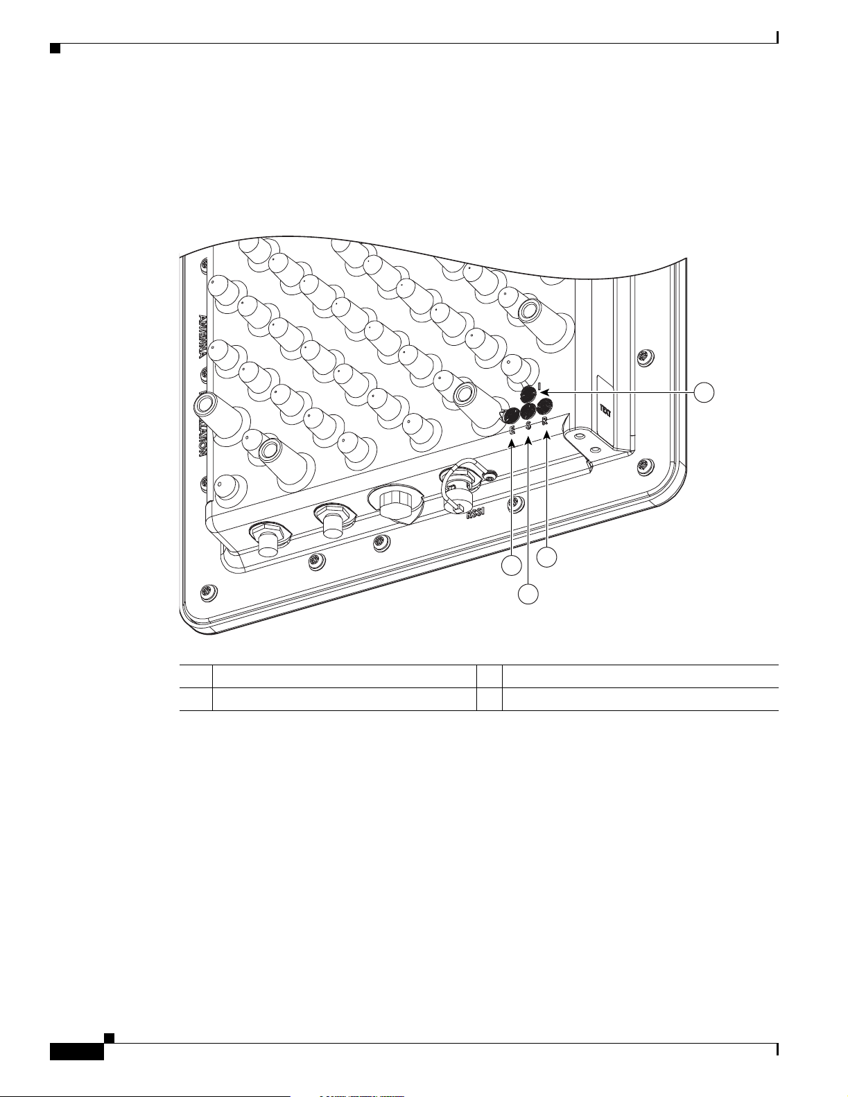
Checking the LED Indicators
DRAFT - CISCO CONFIDENTIAL
Checking the LED Indicators
If your bridge is not associating with the remote bridge, check the four LED indica tors on the back panel.
You can use them to quickly assess th e unit’s status. Figure 5-1 shows the indicators.
Figure 5-1 Bridge LED Indicators
Chapter 5 Troubleshooting
4
88818
3
1
2
1 Ethernet LED 3 Radio L E D
2 Status LED 4 Install LED
The indicators signals have the following meanings (for additional details refer to Table 5-3):
• The status indicator signals bridge association status. Blinking green indicates that the bridge is not
associated with ano ther b ridge. Steady gree n indica tes th at the brid ge is ass ociat ed with at least o ne
other bridge. This indic ator also provide s signal stre ngth read ings during i nstalla tion mod e.
• The radio indicator blinks green to indicate radio traffic activity. The light is normally off, but it
blinks green wh enever a packet is received or transmitted over the bridge radio lin k. This indicator
also provides signal st reng th rea ding s d uring inst al lati on mo de .
• The Ethernet indicator signals Ethernet traffic. This indicator blinks green when a packet is received
or transmitted over the Ethernet infrastructure. The indicator is off when the Ethernet link not
working or the port is shutdown. This indicator also provides signal strength readings during
installation mode.
5-2
• The install indi cator pr ovides in stall atio n m ode asso cia tio n s tatus. Dur ing in stall atio n m ode, the
other indicators p rovid e si gnal str eng th r eadi ngs u sed f or ant enn a a lig nment .
Cisco Aironet 1400 Series Wireless Bridge Hardware Installation Guide
OL-4072-01
Page 55

Chapter 5 Troubleshooting
DRAFT - CISCO CONFIDENTIAL
Bridge Installation Mode LED Indications
When the bridge is initially powered-up, installation mode is activated and the bridge attempts to
associate to a root bridge for 60 seconds. If it is unable to associate with a root bridge, it automatically
assumes the root bridge role. The Install LED provides bridge association status during installation mode
as shown in Table 5-1.
Table 5-1 Install LED Association Status
Install LED State Bridge State
Off Self test Startup
Amber blink Non-root, searchi ng Not associated ( non -root m ode). T he
Amber solid Non-root, associated Asso ciated (n on-roo t mode)
Green blink Root, searching Not associated ( roo t mo de). T he br i dge
Green solid Root, associated Associated (root mode)
1. Pre-configured bridges search indefinitely.
Checking the LED Indicators
bridge attempts to associate with a root
bridge for 60 sec ond s
1
.
attempts to a ssoci ate wi th a non- ro ot
bridge indefinitely.
You use the Install LED to determine when the bridge successfully associates with a remote bridge and
to verify its mode of operation. A fter associat ion, the other three LEDs indicat e signal stre ngth (see
Table 5-2).
Note For the signal leve l (dBm), a smaller number represents a stronger signal because the signal le vel is gi ven
as a negative value.
Table 5-2 LED Installation Mode Signal Strength Display
Signal Level (dBm) Ethernet LED Status LED Radio LED
>-44 On On On
-47 to -44 Fast blink On On
-50 to -47 Me dium blin k On On
-53 to -50 Slow blink On On
-54 to -53 Off On On
-57 to -54 O ff Fast blink On
-60 to -57 O ff Medium blink On
-63 to -60 Off Slow blink On
-66 to -63 O ff Off On
-69 to -66 Off Off Fast blink
-72 to -69 Off Off Medium blink
OL-4072-01
Cisco Aironet 1400 Series Wireless Bridge Hardware Installation Guide
5-3
Page 56

Checking the LED Indicators
DRAFT - CISCO CONFIDENTIAL
Table 5-2 LED Installation Mode Signal Strength Display (continued)
Signal Level (dBm) Ethernet LED Status LED Radio LED
-75 to -72 Off Off Slow blink
< -75 Off Off Off
When using LEDs to maximize the signal, you adjust the antenna until as many LEDs as possible are
turned-on and the rest ar e blink ing as fast as possi ble. With all three LEDS turned-on, the signal is good
enough to suppor t the m axi mum d ata r ate.
Bridge Normal Mode LED Indications
During normal opera ti on t he br idge L EDs pr ovide sta tus i nf orma tio n as shown in Table 5-3.
Table 5-3 Bridge Normal Mode LED Indications
Chapter 5 Troubleshooting
Ethernet
Indicator
Status
Indicator
Radio
Indicator
Meaning
Off - - Ethernet link is d own or di sab led
Green - - Ethernet link is operational
Blinking
- - Transmitting and receiving Ethernet packets
green
Blinking
- - Transmitting and receiving Ethernet errors
amber
amber - - F irmwar e erro r—You should disconnect and re connect the
power injector power jack
- Blinking
green
- Root mode —no remote bridges are associated
Non-root mode—not associated to the root bridge
You should check the SSID and security settings of all
bridges
- Green - Root mode—associated to at least one remote bridge
Non-root mode—associated to the root bridge
Normal oper ati on
- Blinking
- General warning
amber
- Amber - Loadi ng firmware
Red Amber Red Loa ding Firmwar e error—You should disconne ct and
reconnect the power in jec tor power
- - Off Normal operation
- - Blinking
Transmitting and receiving radio packets
green
- - Blinking
amber
Maximum retrie s or buffer ful l oc cu rred on th e r ad io
interface
- - Amber Radio firmware err or —You should disconnect and
reconnect power injector power
5-4
Cisco Aironet 1400 Series Wireless Bridge Hardware Installation Guide
OL-4072-01
Page 57

Chapter 5 Troubleshooting
The bridge uses a blinking code to identify various error conditions. The code sequence uses a two-digit
diagnostic code that starts with a long pause to delimit the code, followed by the indicator flashing red
to count out the first digit, then a short pause, followed by the indicator flashing red to count out the
second digit (see Table 5-4).
Table 5-4 Bridge LED Blinking Error Codes
Power Injector LED Indicators
DRAFT - CISCO CONFIDENTIAL
Blinking Codes
First
Indicator
Ethernet 2 1 Ethernet cable problem—Verify that the cable is properly
Radio 1 2 Radio not detected—Co ntact techni cal support for
Digit
1 3 Radio not ready—Contact technical support for assistance.
1 4 Radio did not start—Co nt act te ch nica l s uppo rt f or
1 5 Radio failure—Contact technical support for assistance.
1 6 Radio did not flash its firmware—Contact technical support
Second
Digit
Description
connected and not def ective. This error might also indi cate a
problem with the Ethernet link. If the cable is connected
properly and not defective, contact technical support for
assistance.
assistance.
assistance.
for assistance.
Power Injector LED Indicators
The power injector contains three LED indicators to provide status information on the wired Ethernet
link, the bridge Ethern et link, an d the brid ge status. Whe n the power inject or is powered up, it send s a
constant discovery tone on the du al-c oax c able s to the b ridg e. When t he bri dge is conn ec te d to the
dual-coax cables, it returns the disco ve ry tone to the po wer injecto r . When the power injector detect s the
returned discovery tone, it applies +48 VDC to the dual-coax cables to the bridge.
When power is applie d to the bridge, th e bridge acti vates th e bootloader and be gins the POST oper ations.
The bridge begins to load the IOS ima ge when the Post operati ons are succ essfull y comple ted. Upon
successfully loading the IOS image, the bridge initializes and tests the radio.
OL-4072-01
Cisco Aironet 1400 Series Wireless Bridge Hardware Installation Guide
5-5
Page 58

Power Injector LED Indicators
The power injector LED indicators are shown in Figure 5-1.
Figure 5-2 Power Injector LED Indicators
DRAFT - CISCO CONFIDENTIAL
7
8
6
Ipsamy opsum
Ipsamy opsum
Ipsamy opsum
Chapter 5 Troubleshooting
1
3
2
5
4
88820
1 Power jack (+ 48 VD C) 5 Ethernet p ort (RJ4 5 con nect or)
2 Power LED indicator 6 Ethernet Activity LED
3 Power injector dual-coax ports (F-Type connectors) 7 Injector Status LED
4 Mode button 8 Uplink Activity LED
The power injector LED indi cati ons are sh own in Table 5-5.
Table 5-5 Power Injector LED Indications
Uplink Activity Injector Status Ethernet Activity Description
- - O ff Wired LAN Ethern et lin k is not ac tive
- - G reen Wired LAN Ethernet link is operati onal
- - Blinking Green Transmitting and receiving packets over the
wired LAN Ethern et link
- - Amber Power injector internal memory error
Off - - L ink betwe en power inject or and bridg e is not
active
Green - - Link between power in jector an d bridg e is
operational
Blinking Green - - Transmittin g and re ceiving E therne t p ackets
between the power injector and the bridge
Amber - - Power injector internal memory error
- Green - Bridge successfully passed Power On Self Test
(POST) and loaded the IOS image
- Blinking Green - Bridge power is active and the bridge is loading
IOS image or POST operation has started
5-6
Cisco Aironet 1400 Series Wireless Bridge Hardware Installation Guide
OL-4072-01
Page 59

Chapter 5 Troubleshooting
DRAFT - CISCO CONFIDENTIAL
Table 5-5 Power Injector LED Indications (continued)
Uplink Activity Injector Status Ethernet Activity Description
- Blinking Amber - Bridge has not been detected and bridge power
Amber Amber Amber Power injector internal memory error
Off Amber Off Bridge is resetting the configuration to def aults;
- Red - Image recovery mode, downloading ne w image;
Red Red Red Power injector internal memory error
Checking Basic Configuration Settings
Mismatched basic settings are the most common causes of lost wireless connectivity. If the bridge does
not associat e wi th a r em ot e bri dge , ch ec k th e f ol lowing ar ea s.
Checking Basic Configuration Settings
is not active
mode button has been depressed more than 2
seconds but less than 20 sec ond s
mode button pressed mo re than 20 se cond s
SSID
To associate, all bridges must use the same SSID. The bridge installation mode SSID is autoinstall and
the normal mode default SSID is tsunami. Y ou should verify the SSID value shown on the Express Setup
page is the same for all bridges. Y ou should also verify the bridges are configured for the proper network
role; only one bridge can be configured as th e root bri dge.
Security Settings
Remote bridges attempting to authenticate with your bridge must support the same security options
configured in the bridge, such as WE P, EAP or LEAP, MAC address au thent ication, Message Int egrity
Check (MIC), WEP key hashi ng, a nd 802.1 X prot ocol vers ions.
If a remote bridge is unable to auth enticate with your bridge, veri fy the security settings a re same as your
bridge settings. For additional information, refer to the Cisco Aironet 1400 Series Bridge Software
Configuration Guide.
OL-4072-01
Cisco Aironet 1400 Series Wireless Bridge Hardware Installation Guide
5-7
Page 60

Antenna Alignment
DRAFT - CISCO CONFIDENTIAL
Antenna Alignment
If your bridges are unable to associate together, you should verify the basic configuration settings on all
bridges before a ttem pti ng to ver ify bri dg e a nten na al ignme nt (r ef er t o “Configuring the Bridge for the
First Time” section on page 4-1). If your basic configurations settings are correct, you can verify antenna
alignment by using the the RSSI port. The RSSI port can be used even when the bridges are not
associated.
Note T o meet re g ulatory res trictio ns, th e ex ternal an tenn a bridg e configuration and the external an tenn a must
be professional insta lled.
The RSSI port outputs a DC voltage that is proportional to the received signal level. The RSSI voltage
is available whenever a signal is present, regardless of the bridge mode (installation or normal),
association status, or pre-configuration role setting. The RSSI voltage provides an instantaneous reading
as you move the antenna . T he RSSI po rt i s a fe m ale BN C conne c tor on the br i dge h ousin g. To obtain
RSSI readings, you can use any convenient voltmeter connected to the RSSI port using a c able with a
male BNC connector.
The RSSI voltage increases linearly with signal level as shown in Table 6.
Chapter 5 Troubleshooting
Note A larger RSSI voltage reading indicates a stronger signal.
Table 6 RSSI Voltage Levels
Nominal Signal Level (dBm) RSSI Reading (volts)
-20 or greater 2.70
-30 2.31
-40 1.93
-50 1.54
-60 1.16
-70 0.77
-80 0.39
-90 or less 0.00
The voltage varies from 0 to 2.7 volts for signals betw een -90 and -20 dBm, respe ctively.
For additional alignment information, refer to the Cisco Aironet 1400 Series Bridge Mounting
Instructions that shipped with your brid ge.
Resetting to the Default Configuration
If you forget the password that allows you to configure the bridge, you may need to completely reset the
configuration. You can use the MODE button on the power injector or the web-browser interface.
Cisco Aironet 1400 Series Wireless Bridge Hardware Installation Guide
5-8
OL-4072-01
Page 61

Chapter 5 Troubleshooting
DRAFT - CISCO CONFIDENTIAL
Note The following steps reset all configuration settings to factory defaults, including passwords, WEP keys,
the IP address, and the SSID.
Using the MODE Button
Follow these steps to de lete th e cu rrent configur ati on a nd ret urn al l br idge set tin gs to fac tor y d efaul ts
using the MODE button:
Step 1 Disconnect the power jac k on the power inject or.
Step 2 Press and hold the MODE button while you reconnect power to the power injector.
Step 3 Hold the MODE button until the Status LED turns amber (approximately 3 seconds), and release the
button.
Step 4 After the bridge reboots, you must reconfigure the bridge by using the Web browser interface, the
Telnet interface, or IOS commands.
Resetting to the Default Configuration
Note The bridge is configured with the factory default values incl uding the IP address (set to receive
an IP address usi ng D HC P). To obtain the bridge ’s new IP address, refer to the “Using the IP
Setup Utility” section on page 4-9.
Using the Web Browser Interface
Follow the steps below to delete the current configuration and return all bridge settings to the factory
defaults using the w eb b rowser int erface.
Step 1 Open your Internet browser. You must use Microsoft Internet Explorer (version 5.x or later) or Netscape
Navigator (version 4.x).
Step 2 Enter the bridge’s IP address in the browser address lin e and press Ente r. An Enter Network Password
screen appears.
Step 3 Enter your use rn ame in th e Us er Na me fiel d .
Step 4 Enter the bri dge password in the Password field a nd pre ss Enter. The Summary Statu s page appea rs.
Step 5 Click System Software and the S yst em So ft ware sc re en a ppea rs.
Step 6 Click System Configuration and the System Configuration screen appears.
Step 7 Click the Default button.
OL-4072-01
Note If the bridge is configured with a static IP address, the IP address does not change.
Step 8 After the bridge reboots, you must reconfigure the bridge by using the Web bro wser interface, the T elnet
interface, or IOS commands.
Cisco Aironet 1400 Series Wireless Bridge Hardware Installation Guide
5-9
Page 62

Reloading the Bridge Image
DRAFT - CISCO CONFIDENTIAL
Reloading the Bridge Image
If your bridge h as a firmware fa ilu re, you m ust r eloa d the com pl ete b ri dge im age file u si ng t he Web
browser interface or by pr essing and holding the MODE button fo r around 30 seconds. You can use the
browser interface if the bridge firmware is still fully operational and you want to upgrade the firmware
image. However, you can use the MODE button when the bridge has a corrupt firmware image.
Using the MODE button
You can use the MODE button on the bridge to reload the bridge image file from an active Trivial File
Transfer Protocol (TFTP) se rver on yo ur ne twork or o n a PC con ne cte d to the b ridge Et hern et por t.
Note If your bridge experiences a firmware failure or a co rrupt firmware image, i ndicate d by three red LE D
indicators, you must reload the imag e from a conn ect ed TFTP ser ver.
Chapter 5 Troubleshooting
Note This process resets all co nfiguration setting s to factory default s, includi ng passwords, WEP keys, the
bridge IP address, and SSID s.
Follow the steps below to reload the bridge image file:
Step 1 The PC you intend to use must be conf igured with a static I P address in the range o f 10.0.0.2 to 10.0.0.30.
Step 2 Make sure the PC contain s the bri dge imag e file (TBD) in the TFTP server folder and the TFTP server
is activated. For additional information, refer to the “Obtaining the Bridge Image File” and “Obtaining
the TFTP Server Software” sections.
Step 3 Connect the PC to the bridge using a Category 5 (CAT5) Ethernet cable.
Step 4 Disconnect the power jac k from the power injector.
Step 5 Press and hold the MODE button while you reconnect power to the power injector.
Step 6 Hold the MODE button un til th e st atu s L ED turn s red (a pproxim ate ly 2 0 to 3 0 seconds), and release the
MODE button.
Step 7 Wait until the bridge reboots as indicated by all LEDs turning green followed by the Status LED
blinking green.
Step 8 After the bridge reboots, you must reconfigure the bridge by using the Web interface, the Telnet
interface, or IOS commands.
Note The bridge is configured with the factory default values including the IP address (set to receive an IP
address using DHCP). To obtain the bridge’s new IP address, refer to th e “Using the IP Setup Utility”
section on page 4-9.
5-10
Cisco Aironet 1400 Series Wireless Bridge Hardware Installation Guide
OL-4072-01
Page 63

Chapter 5 Troubleshooting
DRAFT - CISCO CONFIDENTIAL
Web Browser Interface
You can also use the Web browser interface to reload the bridge image file. The Web browser interface
supports loading the image file using HTTP or TFTP interfaces.
Note Your bridge configurat ion is not ch ange d when usin g the browser to relo ad the im age file.
Browser HTTP Interface
The HTTP interface en ab les you to br owse to the bridge image file on y our PC and d ownload the image
to the bridge. Follow the instructions below to use the HTTP interface:
Step 1 Open your Internet browser. You must use Microsoft Internet Explorer (version 5.x or later) or Netscape
Navigator (version 4.x).
Step 2 Enter the bridge’s IP address in the browser address lin e and press Ente r. An Enter Network Password
screen appears.
Reloading the Bridge Image
Step 3 Enter your use rn ame in th e Us er Na me fiel d .
Step 4 Enter the bri dge password in the Password field a nd pre ss Enter. The Summary Statu s page appea rs.
Step 5 Click the System Software tab and then click Software Upgrade. The HTTP Upgrade screen appears.
Step 6 Click the Browse button to locate the image file on your PC.
Step 7 Click the Upload button.
For additional information, click the Help icon on the Software Upgrade scree n.
Browser TFTP Interface
The TFTP interface allows you to use a TFTP server on a network device to load the bridge image file.
Follow the instructions below to use a TFTP server:
Step 1 Open your Internet browser. You must use Microsoft Internet Explorer (version 5.x or later) or Netscape
Navigator (version 4.x).
Step 2 Enter the bridge’s IP address in the browser address lin e and press Ente r. An Enter Network Password
screen appears.
Step 3 Enter your use rn ame in th e Us er Na me fiel d .
Step 4 Enter the bri dge password in the Password field a nd pre ss Enter. The Summary Statu s page appea rs.
OL-4072-01
Step 5 Click the System Software tab and then click Software Upgrade. The HTTP Upgrade screen appears.
Step 6 Click the TFTP Upgrade tab.
Step 7 Enter the IP address for the TFTP server in the TFTP Server field.
Step 8 Enter the file name for the bridge image file in the Upload New System Image Tar File field. If the file
is located in a subdirectory of the TFTP serve r root directory , include th e relative path of the TFTP server
root directory with t he filename. If the file is lo cat ed in the TFTP root directory, enter only the filen ame.
Step 9 Click the Upload button.
Cisco Aironet 1400 Series Wireless Bridge Hardware Installation Guide
5-11
Page 64

Reloading the Bridge Image
DRAFT - CISCO CONFIDENTIAL
For additional information click the Help icon on the Software Upgrade screen.
Obtaining the Bridge Image File
The bridge image file can be obtained from the Cisco.com software center using the following steps:
IPSU is available on the Cisco web site. Follow these steps to obtain and install IPSU:
Step 1 Step 1 Use your web browser to go to the Cisco So ftware Cente r at the fo llowing URL:
http://www.cisco.com/public/sw-center/sw-wireless.shtml
Step 2 Select Option #1: Aironet Wireless Software Selector.
Step 3 For the Product Type, select Wireless Brid g e and cl ick Submit.
Step 4 Select 1400 Series for the mo del numbe r and cli ck Submit.
Step 5 Select Current Release (Recommended) and click Submit.
Chapter 5 Troubleshooting
Step 6 Select the latest bridge image file (TBD).
Step 7 On the Encryption Authorization Form, enter the requested information, read the encryption
information, and check the boxes that apply. Click Submit.
Step 8 Read and accept the terms and conditions of the Software License Agreement.
Step 9 Select the latest bridge image file again to download it.
Step 10 Save the file to a directory on your hard drive and then exit the Intern et browser.
Obtaining the TFTP Server Software
You can download TFTP server software from several web sites. Cisco recommends the shareware TFTP
utility available at this URL:
http://tftpd32.jounin.net
Follow the instructions on the website for installing and using the utility.
5-12
Cisco Aironet 1400 Series Wireless Bridge Hardware Installation Guide
OL-4072-01
Page 65

DRAFT - CISCO CONFIDENTIAL
APPENDIX
A
Translated Safety Warnings
This appendix provides translations of the safety warnings that appear in this publication. These
translated warnings apply to other documents in which they appear in English. The following safety
warnings appear in thi s ap pendi x:
• Installation Warning, page A-3
• Installation and G rou nding Warning, page A-4
• Circuit Breaker Warning, page A-6
• Ground Conductor Warning, page A-7
• Installation Warning, page A-9
• Lightning Activity Warning, page A-10
• Explosive Device Proximity Warning, page A-11
• Bridge Antenna Exposur e Limits -T BD, page A-1 1
OL-4072-01
Cisco Aironet 1400 Series Wireless Bridge Hardware Installation Guide
A-1
Page 66

Warning Definition
Warning Definition
Appendix A Translated Safety Warnings
DRAFT - CISCO CONFIDENTIAL
Warning
Waarschuwing
Varoitus
Attention
Warnung
This warning symbol means danger. You are in a situation that could cause bodily injury. Before
you work on any equipment, be aware of the hazards involved with electrical circuitry and be
familiar with standard practices for preventing accidents. (To see translations of the warnings
that appear in this publication, refer to the appendix “Translated Safety Warnings.”)
Dit waarschuwingssymbool betekent gevaar. U verkeert in een situatie die lichamelijk letsel kan
veroorzaken. Voordat u aan enige apparatuur gaat werken, dient u zich bewust te zijn van de bij
elektrische schakelingen betrokken risico’s en dient u op de hoogte te zijn van standaard
maatregelen om ongelukken te voorkomen. (Voor vertalingen van de waarschuwingen die in deze
publicatie verschijnen, kunt u het aanhangsel “Translated Safety Warnings” (Vertalingen van
veiligheidsvoorschriften) raadplegen.)
Tämä varoitusmerkki merkitsee vaaraa. Olet tilanteessa, joka voi johtaa ruumiinvammaan. Ennen
kuin työskentelet minkään laitteiston parissa, ota selvää sähkökytkentöihin liittyvistä vaaroista
ja tavanomaisista onnettomuuksien ehkäisykeinoista. (Tässä julkaisussa esiintyvien varoitusten
käännökset löydät liitteestä "Translated Safety Warnings" (käännetyt turvallisuutta koskevat
varoitukset).)
Ce symbole d’avertissement indique un danger. Vous vous trouvez dans une situation pouvant entraîner des blessures. Avant d’accéder à cet équipement, soyez conscient des dangers posés par
les circuits électriques et familiarisez-vous avec les procédures courantes de prévention des accidents. Pour obtenir les traductions des mises en garde figurant dans cette publication, veuillez
consulter l’annexe intitulée « Translated Safety Warnings » (Traduction des avis de sécurité).
Dieses Warnsymbol bedeutet Gefahr. Sie befinden sich in einer Situation, die zu einer Körperver-
letzung führen könnte. Bevor Sie mit der Arbeit an irgendeinem Gerät beginnen, seien Sie sich der
mit elektrischen Stromkreisen verbundenen Gefahren und der Standardpraktiken zur Vermeidung
von Unfällen bewußt. (Übersetzungen der in dieser Veröffentlichung enthaltenen Warnhinweise
finden Sie im Anhang mit dem Titel “Translated Safety Warnings” (Übersetzung der Warnhinweise).)
A-2
Avvertenza
Advarsel
Aviso
Cisco Aironet 1400 Series Wireless Bridge Hardware Installation Guide
Questo simbolo di avvertenza indica un pericolo. Si è in una situazione che può causare infortuni.
Prima di lavorare su qualsiasi apparecchiatura, occorre conoscere i pericoli relativi ai circuiti
elettrici ed essere al corrente delle pratiche standard per la prevenzione di incidenti. La traduzione delle avvertenze riportate in questa pubblicazione si trova nell’appendice, “Translated Safety Warnings” (Traduzione delle avvertenze di sicurezza).
Dette varselsymbolet betyr fare. Du befinner deg i en situasjon som kan føre til personskade. Før
du utfører arbeid på utstyr, må du være oppmerksom på de faremomentene som elektriske kretser
innebærer, samt gjøre deg kjent med vanlig praksis når det gjelder å unngå ulykker. (Hvis du vil
se oversettelser av de advarslene som finnes i denne publikasjonen, kan du se i vedlegget "Translated Safety Warnings" [Oversatte sikkerhetsadvarsler].)
Este símbolo de aviso indica perigo. Encontra-se numa situação que lhe poderá causar danos fisicos. Antes de começar a trabalhar com qualquer equipamento, familiarize-se com os perigos
relacionados com circuitos eléctricos, e com quaisquer práticas comuns que possam prevenir
possíveis acidentes. (Para ver as traduções dos avisos que constam desta publicação, consulte
o apêndice “Translated Safety Warnings” - “Traduções dos Avisos de Segurança”).
OL-4072-01
Page 67

Appendix A Translated Safety Warnings
DRAFT - CISCO CONFIDENTIAL
Installation Warning
¡Advertencia!
Varning!
Este símbolo de aviso significa peligro. Existe riesgo para su integridad física. Antes de manipular cualquier equipo, considerar los riesgos que entraña la corriente eléctrica y familiarizarse
con los procedimientos estándar de prevención de accidentes. (Para ver traducciones de las advertencias que aparecen en esta publicación, consultar el apéndice titulado “Translated Safety
Warnings.”)
Denna varningssymbol signalerar fara. Du befinner dig i en situation som kan leda till personskada. Innan du utför arbete på någon utrustning måste du vara medveten om farorna med elkretsar
och känna till vanligt förfarande för att förebygga skador. (Se förklaringar av de varningar som
förekommer i denna publikation i appendix "Translated Safety Warnings" [Översatta säkerhetsvarningar].)
Installation Warning
Warning
Waarschuwing
Only trained and qualified personnel should be allowed to install, replace, or service
this equipment.
Deze apparatuur mag alleen worden geïnstalleerd, vervangen of hersteld door bevoegd
geschoold personeel.
Varoitus
Attention
Warnung
Figyelem!
Avvertenza
Advarsel
Aviso
¡Advertencia!
Varning!
Tämän laitteen saa asentaa, vaihtaa tai huoltaa ainoastaan koulutettu ja laitteen
tunteva henkilökunta.
Il est vivement recommandé de confier l'installation, le remplacement et la maintenance de ces
équipements à des personnels qualifiés et expérimentés.
Das Installieren, Ersetzen oder Bedienen dieser Ausrüstung sollte nur geschultem, qualifiziertem
Personal gestattet werden.
A berendezést csak szakképzett személyek helyezhetik üzembe, cserélhetik és tarthatják karban.
Questo apparato può essere installato, sostituito o mantenuto unicamente da un personale
competente.
Bare opplært og kvalifisert personell skal foreta installasjoner, utskiftninger eller service på
dette utstyret.
Apenas pessoal treinado e qualificado deve ser autorizado a instalar, substituir ou fazer a revisão
deste equipamento.
Solamente el personal calificado debe instalar, reemplazar o utilizar este equipo.
Endast utbildad och kvalificerad personal bör få tillåtelse att installera, byta ut eller reparera
denna utrustning.
OL-4072-01
Cisco Aironet 1400 Series Wireless Bridge Hardware Installation Guide
A-3
Page 68

Installation and Grounding Warning
DRAFT - CISCO CONFIDENTIAL
Installation and Grounding Warning
Appendix A Translated Safety Warnings
Warning
Waarschuwing
Varoitus
Attention
Do not locate the antenna near overhead power lines or other electric light or power circuits, or
where it can come into contact with such circuits. When installing the antenna, take extreme care
not to come into contact with such circuits, because they may cause serious injury or death. For
proper installation and grounding of the antenna, please refer to national and local codes (for
example, U.S.:NFPA 70, National Electrical Code, Article 810, Canada: Canadian Electrical Code,
Section 54).
Zorg dat antenne niet in de buurt wordt geplaatst van langs het plafond lopende stroomkabels of
andere voorzieningen voor licht of elektriciteit of op een plaats waar contact met dergelijke
stroomvoorzieningen mogelijk is. Wees bij het installeren van de antenne voorzichtig dat u niet in
contact komt met dergelijke stroomvoorzieningen aangezien dit kan leiden to ernstig lichamelijk of
dodelijk letsel. Voor het juist installeren en aarden van de antenne, dient u de nationale en
plaatselijke verordeningen te raadplegen (bijv. in de VS NFPA 70, National Electrical Code, Artikel
810, in Canada: Canadian Electrical Code, Sectie 54).
Älä sijoita antennia lähelle voimajohtoja, muita sähkövalo- tai virtapiirejä tai paikkaa, jossa se voi
joutua kosketuksiin sellaisten piirien kanssa. Kun asennat antennia, varo, ettet joudu kosketuksiin
mainittujen piirien kanssa, sillä seurauksena voi olla vakava vamma tai kuolema. Tarkista antennin
asennus- ja maadoitustiedot kansallisista ja paikallisista sähkösäännöksistä (esimerkiksi
Yhdysvalloissa NFPA 70, National Electrical Code, Article 810 ja Kanadassa Canadian Electrical
Code, Section 54).
Ne placez pas l'antenne à proximité d'une ligne aérienne ou d'autres circuits d'éclairage ou
d'alimentation, ou dans un endroit où elle risque d'être en contact avec des circuits de ce type. Lors
de son installation, assurez-vous bien qu'elle ne touche pas de tels circuits car cela risquerait
d'entraîner des blessures graves, voire mortelles. Pour une installation et mise à la terre correctes
de l'antenne, veuillez consulter les codes nationaux et locaux (par exemple, États-Unis : NFPA 70,
National Electrical Code, Article 810 ; Canada : Code électrique canadien, Section 54).
A-4
Cisco Aironet 1400 Series Wireless Bridge Hardware Installation Guide
OL-4072-01
Page 69

Appendix A Translated Safety Warnings
DRAFT - CISCO CONFIDENTIAL
Installation and Grounding Warning
Warnung
Figyelem!
Avvertenza
Advarsel
Platzieren Sie die Antenne nicht in der Nähe von Starkstrom-Freileitungen oder Schwach- bzw.
Starkstromkreisen oder an Stellen, wo sie damit in Kontakt kommen könnte. Gehen Sie bei der
Installation der Antenne besonders vorsichtig vor, damit Sie nicht in Kontakt mit derartigen
Stromkreisen kommt, da dies zu schweren Verletzungen sogar mit Todesfolge führen kann.
Installieren und erden Sie die Antenne sachgerecht unter Einhaltung der jeweils gültigen
Sicherheitsvorschriften (zum Beispiel USA: NFPA 70, National Electrical Code, Artikel 810 oder
Kanada: Canadian Electrical Code, Abschnitt 54).
Ne helyezze az antennát elektromos felsõvezetékek és más elektromos világítási és tápellátási
áramkörök közelébe, és semmilyen olyan környezetbe, ahol ilyen áramkörökkel érintkezhet. Az
antenna felszerelésekor különösképpen ügyeljen arra, hogy ne kerüljön érintkezésbe ilyen
áramkörökkel, mert az súlyos sérülést vagy halált okozhat. Az antenna helyes üzembe helyezésével
és földelésével kapcsolatban az országos és helyi elõírások tartalmaznak útmutatást (például az
USA-ban: NFPA 70, National Electrical Code, Article 810, Kanadában: Canadian Electrical Code,
Section 54).
Non sistemare l'antenna nelle vicinanze di circuiti elettrici generali o di altri circuiti di
illuminazione o di alimentazione, o dove questa possa venire a contatto con tali circuiti. Durante
l'installazione dell'antenna, prestare particolare attenzione a non entrare in contatto con tali
circuiti, in quanto questo potrebbe provocare seri danni o morte. Per una corretta installazione e
messa a terra dell'antenna, fare riferimento ai codici nazionali e locali (es. U.S.A.: NFPA 70, Codice
Elettrico Nazionale, articolo 810, Canada: Codice Elettrico Canadese, sezione 54).
Plasser ikke antennen nær de overliggende strømledningene eller andre lys- eller strømkretser,
eller der den kan komme i kontakt med slike kretser. Ved installering av antennen må du være ytterst
forsiktig slik at du ikke kommer i kontakt med slike kretser. Dette kan føre til alvorlig skade eller
død. For riktig installasjon og jording av antennen, se statlige og lokale forskrifter (for eksempel i
USA: NFPA 70, National Electrical Code, Article 810, og i Canada: Canadian Electrical Code,
Section 54).
Aviso
¡Advertencia!
Varning!
Não coloque a antena perto de linhas de alimentação, de outros circuitos ou onde possa entrar em
contato com esses circuitos. Ao instalar a antena, tenha muito cuidado para não tocar nesses
circuitos, visto que podem provocar ferimentos graves ou até a morte. Para obter informações sobre
como instalar e aterrar corretamente a antena, consulte a legislação local e nacional (por ex., U.S.:
NFPA 70, National Electrical Code, Artigo 810, Canadá: Canadian Electrical Code, Seção 54).
No coloque la antena cerca de cables de tendido eléctrico u otros circuitos eléctricos, ni donde
pueda entrar en contacto con los mismos. Al instalar la antena, extreme las precauciones para no
entrar en contacto con dichos circuitos, ya que puede causar heridas graves e incluso la muerte.
Para instalar la antena y conectarla a tierra correctamente, consulte los códigos nacionales y
locales (p.ej., Estados Unidos: NFPA 70, National Electrical Code, Sección 810, Canadá: Canadian
Electrical Code, Artículo 54).
Placera inte antennen nära överhängande kraftledningar, andra elljus- eller strömkretsar eller där
den kan komma i kontakt med sådan kretsar. Vid installation av antennen måste du vara mycket
försiktig så att du inte kommer i kontakt med sådana kretsar eftersom de kan orsaka allvarlig
kroppsskada eller dödsfall. För riktig installation och jordning av antennen, hänvisas du till
nationella och lokala koder (t.ex. USA: NFPA 70, National Electrical Code, Article 810, Kanada:
Canadian Electrical Code, Section 54).
OL-4072-01
Cisco Aironet 1400 Series Wireless Bridge Hardware Installation Guide
A-5
Page 70

Circuit Breaker Warning
Appendix A Translated Safety Warnings
DRAFT - CISCO CONFIDENTIAL
Circuit Breaker Warning
Warning
Waarschuwing
Varoitus
Attention
Warnung
This product relies on the building’s installation for short-circuit (overcurrent) protection. Ensure
that the protective device is rated not greater than:
120Vac, 15A U.S. (240Vac, 10A International)
Dit product is afhankelijk van de installatie van het gebouw voor beveiliging tegen kortsluiting
(overstroom). Controleer of de beschermingsinrichting niet meer dan:
120Vac, 15A U.S. (240Vac, 10A International)
Tämä tuote on riippuvainen rakennukseen asennetusta oikosulkusuojauksesta
(ylivirtasuojauksesta). Varmista, että suojalaitteen mitoitus ei ole yli:
120Vac, 15A U.S. (240Vac, 10A International)
Pour ce qui est de la protection contre les courts-circuits (surtension), ce produit dépend de
l'installation électrique du local. Vérifiez que le courant nominal du dispositif de protection n'est
pas supérieur à :
120Vac, 15A U.S. (240Vac, 10A International)
Dieses Produkt ist darauf angewiesen, dass im Gebäude ein Kurzschluss- bzw. Überstromschutz
installiert ist. Stellen Sie sicher, dass der Nennwert der Schutzvorrichtung nicht mehr als:
120Vac, 15A U.S. (240Vac, 10A International)
is.
beträgt.
A-6
Figyelem!
Cisco Aironet 1400 Series Wireless Bridge Hardware Installation Guide
A termék védelmi rendszerének része az épület kábelezésébe épített rövidzárlat (túláram) elleni
védelem is. Gondoskodjon róla, hogy a készüléket védõ eszköz legfeljebb
120Vac, 15A U.S. (240Vac, 10A International)
áramerõsségre legyen méretezve.
OL-4072-01
Page 71

Appendix A Translated Safety Warnings
DRAFT - CISCO CONFIDENTIAL
Ground Conductor Warning
Avvertenza
Advarsel
Aviso
¡Advertencia!
Varning!
Questo prodotto dipende dall'impianto dell'edificio per quanto riguarda la protezione contro
cortocircuiti (sovracorrente). Assicurarsi che il dispositivo di protezione non abbia un rating
superiore a:
120Vac, 15A U.S. (240Vac, 10A International)
Dette produktet er avhengig av bygningens installasjoner av kortslutnings (overstrøm)-beskyttelse.
Påse at verneenheten ikke er merket høyere enn:
120Vac, 15A U.S. (240Vac, 10A International)
Este produto depende das instalações existentes para proteção contra curto-circuito (sobrecarga).
Assegure-se de que o fusível ou disjuntor não seja superior a:
120Vac, 15A U.S. (240Vac, 10A International)
Este equipo utiliza el sistema de protección contra cortocircuitos (o sobrecorrientes) del edificio. Asegúrese
de que el dispositivo de protección no sea superior a:
120Vac, 15A U.S. (240Vac, 10A International)
Denna produkt är beroende av i byggnaden installerat kortslutningsskydd (överströmsskydd).
Kontrollera att skyddsanordningen inte har högre märkvärde än:
120Vac, 15A U.S. (240Vac, 10A International)
120Vac, 15A U.S. (240Vac, 10A International)
120Vac, 15A U.S. (240Vac, 10A International)
120Vac, 15A U.S. (240Vac, 10A International)
Ground Conductor Warning
Warning
Waarschuwing
This equipment must be grounded. Never defeat the ground conductor or operate the equipment in
the absence of a suitably installed ground conductor. Contact the appropriate electrical inspection
authority or an electrician if you are uncertain that suitable grounding is available.
Deze apparatuur dient geaard te zijn. De aardingsleiding mag nooit buiten werking worden gesteld
en de apparatuur mag nooit bediend worden zonder dat er een op de juiste wijze geïnstalleerde
aardingsleiding aanwezig is. Neem contact op met de bevoegde instantie voor elektrische
inspecties of met een elektricien als u er niet zeker van bent dat er voor passende aarding
gezorgd is.
OL-4072-01
Cisco Aironet 1400 Series Wireless Bridge Hardware Installation Guide
A-7
Page 72

Ground Conductor Warning
Appendix A Translated Safety Warnings
DRAFT - CISCO CONFIDENTIAL
Varoitus
Attention
Warnung
Figyelem!
Avvertenza
Advarsel
Laitteiden on oltava maadoitettuja. Älä koskaan ohita maajohdinta tai käytä laitteita ilman oikein
asennettua maajohdinta. Ota yhteys sähkötarkastusviranomaiseen tai sähköasentajaan, jos olet
epävarma maadoituksen sopivuudesta.
Cet équipement doit être mis à la masse. Ne jamais rendre inopérant le conducteur de masse ni
utiliser l'équipement sans un conducteur de masse adéquatement installé. En cas de doute sur la
mise à la masse appropriée disponible, s'adresser à l'organisme responsable de la sécurité
électrique ou à un électricien.
Dieses Gerät muss geerdet sein. Auf keinen Fall den Erdungsleiter unwirksam machen oder das
Gerät ohne einen sachgerecht installierten Erdungsleiter verwenden. Wenn Sie sich nicht sicher
sind, ob eine sachgerechte Erdung vorhanden ist, wenden Sie sich an die zuständige
Inspektionsbehörde oder einen Elektriker.
A berendezés csak megfelelõ védõföldeléssel mûködtethetõ. Ne iktassa ki a földelés csatlakozóját,
és ne üzemeltesse a berendezést szabályosan felszerelt földelõ vezeték nélkül! Ha nem biztos
benne, hogy megfelelõ földelés áll rendelkezésbe, forduljon a helyi elektromos hatóságokhoz vagy
egy villanyszerelõhöz.
Questa apparecchiatura deve essere dotata di messa a terra. Non escludere mai il conduttore di
protezione né usare l'apparecchiatura in assenza di un conduttore di protezione installato in modo
corretto. Se non si è certi della disponibilità di un adeguato collegamento di messa a terra,
richiedere un controllo elettrico presso le autorità competenti o rivolgersi a un elettricista.
Dette utstyret må jordes. Omgå aldri jordingslederen og bruk aldri utstyret uten riktig montert
jordingsleder. Ta kontakt med fagfolk innen elektrisk inspeksjon eller med en elektriker hvis du er
usikker på om det finnes velegnet jordning.
Aviso
¡Advertencia!
Varning!
Este equipamento deve ser aterrado. Nunca anule o fio terra nem opere o equipamento sem um
aterramento adequadamente instalado. Em caso de dúvida com relação ao sistema de aterramento
disponível, entre em contato com os serviços locais de inspeção elétrica ou um eletricista
qualificado.
Este equipo debe estar conectado a tierra. No inhabilite el conductor de tierra ni haga funcionar el
equipo si no hay un conductor de tierra instalado correctamente. Póngase en contacto con la
autoridad correspondiente de inspección eléctrica o con un electricista si no está seguro de que
haya una conexión a tierra adecuada.
Denna utrustning måste jordas. Koppla aldrig från jordledningen och använd aldrig utrustningen
utan en på lämpligt sätt installerad jordledning. Om det föreligger osäkerhet huruvida lämplig
jordning finns skall elektrisk besiktningsauktoritet eller elektriker kontaktas.
A-8
Cisco Aironet 1400 Series Wireless Bridge Hardware Installation Guide
OL-4072-01
Page 73
Appendix A Translated Safety Warnings
DRAFT - CISCO CONFIDENTIAL
Installation Warning
Installation Warning
Warning
Waarschuwing
Varoitus
Attention
Warnung
Figyelem!
Avvertenza
Advarsel
Aviso
¡Advertencia!
Varning!
Read the installation instructions before connecting the system to the power source.
Raadpleeg de installatie-instructies voordat u het systeem op de voedingsbron aansluit.
Lue asennusohjeet ennen järjestelmän yhdistämistä virtalähteeseen.
Avant de brancher le système sur la source d'alimentation, consulter les directives d'installation.
Vor dem Anschließen des Systems an die Stromquelle die Installationsanweisungen lesen.
Mielõtt áramforráshoz csatlakoztatná a rendszert, olvassa el az üzembe helyezési útmutatót!
Consultare le istruzioni di installazione prima di collegare il sistema all'alimentatore.
Les installasjonsinstruksjonene før systemet kobles til strømkilden.
Leia as instruções de instalação antes de ligar o sistema à fonte de energia.
Lea las instrucciones de instalación antes de conectar el sistema a la red de alimentación.
Läs installationsanvisningarna innan du kopplar systemet till strömförsörjningsenheten.
OL-4072-01
Cisco Aironet 1400 Series Wireless Bridge Hardware Installation Guide
A-9
Page 74

Lightning Activity Warning
DRAFT - CISCO CONFIDENTIAL
Lightning Activity Warning
Appendix A Translated Safety Warnings
Warning
Waarschuwing
Varoitus
Attention
Warnung
Figyelem!
Avvertenza
Advarsel
Aviso
¡Advertencia!
Do not work on the system or connect or disconnect cables during periods of lightning activity.
Tijdens onweer dat gepaard gaat met bliksem, dient u niet aan het systeem te werken of kabels aan
te sluiten of te ontkoppelen.
Älä työskentele järjestelmän parissa äläkä yhdistä tai irrota kaapeleita ukkosilmalla.
Ne pas travailler sur le système ni brancher ou débrancher les câbles pendant un orage.
Arbeiten Sie nicht am System und schließen Sie keine Kabel an bzw. trennen Sie keine ab, wenn
es gewittert.
Villámlás közben ne dolgozzon a rendszeren, valamint ne csatlakoztasson és ne húzzon ki
kábeleket!
Non lavorare sul sistema o collegare oppure scollegare i cavi durante un temporale con fulmini.
Utfør aldri arbeid på systemet, eller koble kabler til eller fra systemet når det tordner eller lyner.
Não trabalhe no sistema ou ligue e desligue cabos durante períodos de mau tempo (trovoada).
No operar el sistema ni conectar o desconectar cables durante el transcurso de descargas
eléctricas en la atmósfera.
Varning!
Vid åska skall du aldrig utföra arbete på systemet eller ansluta eller koppla loss kablar.
A-10
Cisco Aironet 1400 Series Wireless Bridge Hardware Installation Guide
OL-4072-01
Page 75

Appendix A Translated Safety Warnings
DRAFT - CISCO CONFIDENTIAL
Explosive Device Proximity Warning
Explosive Device Proximity Warning
Warning
Waarschuwing
Varoitus
Attention
Warnung
Avvertenza
Advarsel
Aviso
Do not operate your wireless network device near unshielded blasting
ment unless the device has been modified to be especially qualified for such use.
Gebruik dit draadloos netwerkapparaat alleen in de buurt van onbeschermde ontstekers of in
een omgeving met explosieven indien het apparaat speciaal is aangepast om aan de eisen voor
een dergelijk gebruik te voldoen.
Älä käytä johdotonta verkkolaitetta suojaamattomien räjäytysnallien läheisyydessä tai räjäytysalueella, jos laitetta ei ole erityisesti muunnettu sopivaksi sellaiseen käyttöön.oen.
Ne jamais utiliser un équipement de réseau sans fil à proximité d'un détonateur non blindé ou
dans un lieu présentant des risques d'explosion, sauf si l'équipement a été modifié à cet effet.
Benutzen Sie Ihr drahtloses Netzwerkgerät nicht in der Nähe ungeschützter Sprengkapseln oder
anderer explosiver Stoffe, es sei denn, Ihr Gerät wurde eigens für diesen Gebrauch modifiziert
und bestimmt.
Non utilizzare la periferica di rete senza fili in prossimità di un detonatore non protetto o di esplosivi a meno che la periferica non sia stata modificata a tale proposito.
Ikke bruk den trådløse nettverksenheten nært inntil uisolerte fenghetter eller i et eksplosivt miljø med mindre enheten er modifisert slik at den tåler slik bruk.
Não opere o dispositivo de rede sem fios perto de cápsulas explosivas não protegidas ou num
ambiente explosivo, a não ser que o dispositivo tenha sido modificado para se qualificar especialmente para essa utilização.
caps or in an explosive environ-
¡Advertencia!
Varning!
No utilizar un aparato de la red sin cable cerca de un detonador que no esté protegido ni tampoco en un entorno explosivo a menos que el aparato haya sido modificado con ese fin.
Använd inte den trådlösa nätverksenheten i närheten av oskyddade tändhattar eller i en explosiv miljö om inte enheten modifierats för att kunna användas i sådana sammanhang.
Bridge Antenna Exposure Limits -TBD
Warning In order to comply with radio frequency (RF) exposure limits
positioned no less than 6.56 ft (2 m) from your body or nearby persons.
Cisco Aironet 1400 Series Wireless Bridge Hardware Installation Guide
OL-4072-01
, the antennas for this product should be
A-11
Page 76

Bridge Antenna Exposure Limits -TBD
Appendix A Translated Safety Warnings
DRAFT - CISCO CONFIDENTIAL
A-12
Cisco Aironet 1400 Series Wireless Bridge Hardware Installation Guide
OL-4072-01
Page 77

DRAFT - CISCO CONFIDENTIAL
APPENDIX
B
Declarations of Conformity and Regulatory Information
This appendix p rovides de cla rat ions of co nform ity a nd regul at ory inf orm atio n f or the Cisc o Air onet
1400 Series Wireless Bridge.
This appendix cont ai ns the fo llowing sec tio ns:
• Manufacturers Federal Commu nication Com mission Decl aration of Conf ormit y Statemen t, page
B-2
• Department of C ommuni ca tio ns—Canada, page B-3
• Declaration of Conformity for RF Exposure, page B-4
OL-4072-01
Cisco Aironet 1400 Series Wireless Bridge Hardware Installation Guide
B-1
Page 78

Appendix B Declarations of Conformity and Regulatory Information
Manufacturers Federal Communication Commission Declaration of Conformity Statement
DRAFT - CISCO CONFIDENTIAL
Manufacturers Federal Communication Commission
Declaration of Conformity Statement
T ested To Comply
With FCC Standards
FOR HOME OR OFFICE USE
Models: AIR-BR1410A-A-K9
AIR-BR-1410-A-A-K9 -N
FCC Certification number: LDK 1020 47
LDK 102047P
Manufacturer: Cisco Sy stems, Inc .
170 West Tasman Drive
San Jose, CA 95134- 170 6
USA
This device complies with Part 15 rules. Operation is subject to the following two conditions:
1. This device may not ca use h ar mf ul i nte rf er ence , an d
2. This device mu s t ac cep t any interference recei ved, including interference that may cau se u ndesired
operation.
This equipment has been tested and found to comply with the limits of a Class B digital device, pursuant
to Part 15 of the FCC Rules. These limits are designed to provide reasonable protection against harmful
interference whe n the equi pmen t is opera ted in a resi dential environment. This eq uipm ent gene rates,
uses, and radiat es r a dio f req uency en ergy, and if not ins tall ed a nd used i n ac co rdanc e w ith the
instructions, may cause harmful interference. However, there is no guarantee that interference will not
occur. If this equipment does cause interference to radio or television reception, which can be determined
by turning the equipment off and on, the user is encouraged to correct the interference by one of the
following measures:
• Reorient or re loca te the r ece iving an tenn a.
• Increase separation between the equipment and receiver.
• Connect the equipment to an outlet on a circuit different from which the receiver is connected.
• Consult the dea ler o r an experi enc ed radi o/T V t ech ni cia n.
Caution The Part 15 radio device operates on a non- int erfe renc e ba sis w ith ot her devices o pera ting a t t his
frequency when using in tegrat ed a nten na s or th ose l iste d in Table B-1. Any changes or mod ification t o
the product not expressly approved by Cisco could void the user’s authority to operate this device.
B-2
Caution To meet regulatory re s trictions, the bridge with the antenna conn ector and the external antenna must be
installed by a professional in staller.
Cisco Aironet 1400 Series Wireless Bridge Hardware Installation Guide
OL-4072-01
Page 79

Appendix B Declarations of Conformity and Regulatory Information
DRAFT - CISCO CONFIDENTIAL
Table B-1 Access Point 2.4-GHz Antennas
Cisco Part Number Model Gain
AIR-ANT58G9VOA-NAironet Vertically polarized
omnidirectional
AIR-ANT58G10SSA-NAironet Sector 9.5 dBi
AIR-ANT58G28SDA-NAironet Dish 28 dBi
Department of Communications—Canada
Canadian Compliance Statement
This Class B Digital apparatus meets all the requirements of the Canadian Interference-Causing
Equipment Regulations.
Department of Communications—Canada
9 dBi
Cet appareil numerique de la classe B respecte les exigences du Reglement sur le material broilleur du
Canada.
This device co mplie s with Class B Lim its o f Indust ry Can ada. Oper ati on is su b jec t to th e following two
conditions:
1. This device may not ca use h ar mf ul i nte rf er ence , an d
2. This device mu s t ac cep t any interference recei ved, including interference that may cau se u ndesired
operation.
Cisco’s 54-Mbps, 5.8-GHz bridge s are c ert ified to th e re quir ements of RSS-210 issue 5, RSP 100, and
RSS 102 for 5-GHz spread spectrum devices.
OL-4072-01
Cisco Aironet 1400 Series Wireless Bridge Hardware Installation Guide
B-3
Page 80

Appendix B Declarations of Conformity and Regulatory Information
This transmitter may not be co-located or operating in conjunction with
other transmitters or antennas separated by less than 2m .
Declaration of Conformity for RF Exposure
DRAFT - CISCO CONFIDENTIAL
Declaration of Conformity for RF Exposure
This bridge product has been fo und to be comp liant to the re quirem ents set forth i n CFR 47
Section 1.1307 addressing RF Exp osure from ra dio freq uency devices as defined in Evaluating
Compliance with FCC Guidelines for Human Exposure to Radio Frequency Electromagnetic Fields. For
antennas, AIR-ANT58G9VOA-NAironet, AIR-ANT58G10SSA-NAironet, and
AIR-ANT58G28SDA-NAironet, the antennas should be po sitio ned more th an 6.8 fe et (2 met ers) fr om
your body or nearby persons.
Cisco Aironet 1400 Series Wireless Bridge Hardware Installation Guide
B-4
OL-4072-01
Page 81

DRAFT - CISCO CONFIDENTIAL
APPENDIX
C
Channels and Antenna Settings
This appendix lists the IEEE 802.11a (5.8-GHz band) channels and the maximum power levels supported
by the Americas regulatory domain.
The following topics are covered in this appendix:
• Channels, page C-2
• Maximum Power Levels, page C-2
OL-4072-01
Cisco Aironet 1400 Series Wireless Bridge Hardware Installation Guide
C-1
Page 82

Channels
DRAFT - CISCO CONFIDENTIAL
Channels
IEEE 802.11a (5.8-GHz Band)
The channel identifiers, channel center frequencies and regulatory domain of each 20-MHz-wide
channel are sh own in Table C-1.
.
Table C-1 Channels for IEEE 802.11a (5.8-GHz Band)
Appendix C Channels and Antenna Settings
Center
Channel
Identifier
149 5745 X
153 5765 X
157 5785 X
161 5805 X
This product is for outdoor use with regard to the channel identifiers indicated in Table C-1.
Frequency
(MHz)
Maximum Power Levels
5.8-GHz Band
An improper combination of power level and antenna configurations can result in equivalent isotropic
radiated power (EIRP) above the amoun t allowed per regul atory do main. Table C-2 indicates the
maximum power levels and antenna gains allowed.
Table C-2 Maximum Power Levels and Antenna Gains
Regulatory Domains
Americas
(-A)
C-2
9 dBi
Omnidirectional
Regulatory Domains
Americas (-A) P2 P
1. Point-to-Point
2. Point-to-Multipoint
3. A maximum of 13 dBm is allowed, but that setting is not supported by the bridge.
4. On point-to-multipoint links, the remote bridges communicating with the central b ridge are allowed to u se a maximum power
setting of 24 dBm. The central bridge is limited to a maximum power setting of 12 dBm.
Cisco Aironet 1400 Series Wireless Bridge Hardware Installation Guide
Orientation
1
2
P2MP
Antenna
24 dBm 24 dBm 24 dBm 22 dBm
24 dBm 24 dBm 123 dBm
Maximum Power Settings
9.5 dBi
Sector
Antenna
22.5 dBi
Integrated
Antenna
4
28 dBi
Dish
Antenna
na
OL-4072-01
Page 83

DRAFT - CISCO CONFIDENTIAL
GLOSSARY
802.11
802.11a
A
Ad Hoc Network
Antenna Gain
Associated
B
Beacon
The IEEE standa rd that spec ifies ca rrie r se nse media a ccess co ntrol and physi cal laye r
specifications for 1- and 2-megab it-pe r-second (Mbps) wireless L ANs operat ing in the 2.4 -GHz
band.
The IEEE standa rd that spec ifies ca rrie r se nse media a ccess co ntrol and physi cal laye r
specifications for wirel ess LANs opera ting in th e 5-GHz frequency ban d.
A wireless network composed of station s without Acce ss Points.
The gain of an antenna i s a meas ur e of the ante nna’s ability to direct or focus radio energy over a
region of space. High ga in a nte nnas h ave a more f ocuse d radi ation pa tt ern in a sp eci fic dire cti on.
A station is configured properly to allow it to wirelessly communicate with an Access Point.
A wireless LAN packet that signals the availability and presence of the wireless device. Beacon
packets are sent by access points and base stations; however , client radio cards send beacons when
operating in computer to com puter (A d Hoc) mode .
BOOTP
Bridge
Broadcast Packet
C
Cell
CSMA
OL-4072-01
Boot Protocol. A protocol used for the static assignment of IP addresses to devices on the network.
A wireless LAN transceiver that is used to in terco nnect two or mor e wired Et hernet net works.
A single data message (pa cket) se nt to a ll addr es ses on t he sa me subn et.
The area of radio range or coverage in which the wireless devices can com mun icate with the base
station. The size of the cell depends upon the speed of the transmission, the type of antenna used,
and the physic al e nvironment , as we ll a s o t her fa ctor s.
Carrier sense multiple ac cess. A wir eless LAN media access meth od specif ied b y the IEEE 802.11
specification.
Cisco Aironet 1400 Series Wireless Bridge Hardware Installation Guide
GL-1
Page 84

D
Glossary
DRAFT - CISCO CONFIDENTIAL
Data Rates
dBi
dBm
DHCP
Dipole
Domain Name
DNS
DSSS
The range of da ta tr an smission ra te s su pport ed by a device. D ata ra tes a re m ea sured i n megabi ts
per second (Mbps).
A ratio of deci bel s to a n is o tropic a nte nna that is c omm on ly us ed to me asu re a nte nna gai n. T he
greater the dBi value, the higher the gain, and the more acute the angle of coverage.
A power measurement described in decibels per milliwatt. 0 dBm is defined as 1 mw at 1 kHz of
frequency at 600 ohms of imped ance.
Dynamic host configuration protocol. A protoco l available with many operating systems th at
automatically issues IP addresses within a specified range to devices on the network. The device
retains the assigned address for a specific administra tor-defined period.
A type of low-gain (2.2-dBi) antenna consisting of two (often internal) elements.
The text name that re f ers t o a gr oup ing o f networks or net work r es ource s b ased on
organization-type or g eog raphy; for exa mple : na me. com—commercial; name.edu—educational;
name.gov—government; ISPname.net—network provider (such as an ISP); name.ar—Argentina;
name.au—Australia; and so on.
Domain Name System server. A server that translates text names into IP addresses. The server
maintains a database of host alp hanumer ic names and their co rresponding IP address es.
Direct sequence spread spectrum. A type of spread spectrum radio transmission that sprea ds its
signal continuously over a wide freq uency band .
E
EAP
Ethernet
F
File Server
Firmware
Extensible Authent icatio n Protocol. A n optional IEEE 802.1 x secur ity feature ideal for
organizations w ith a la r ge us er base and access t o an E AP-enabled Remote Authen tication Dial-In
User Service (R ADI US) se rver.
The most widely used wired local area network. Ethernet uses carrier sense multiple access
(CSMA) to allow computers to share a network and operates at 10, 100, or 1000 Mbps, depending
on the physical la yer u sed .
A repository for files so that a local area network can share files, mail, and programs.
Software tha t is pro gramm e d o n a memor y ch ip .
GL-2
Cisco Aironet 1400 Series Wireless Bridge Hardware Installation Guide
OL-4072-01
Page 85

G
Glossary
DRAFT - CISCO CONFIDENTIAL
Gateway
GHz
I
IEEE
Infrastructure
IP Address
IP Subnet Mask
Isotropic
M
A device that connects two othe rwise inc om patib le n etworks toge the r.
Gigahertz. One billion cycles per second. A unit of measure for frequency.
Institute of Electrical an d Electronic Engineers. A professional society servin g electrical engineer s
through its publications, conferences, and standards development activities. The body responsible
for the Ethernet 802.3 an d wirele ss LAN 802.1 1 specifications.
The wired Et herne t n etwor k.
The Internet Protocol (IP) address of a stat ion.
The number used t o ide ntify the I P su bnet work, indi cati ng whe ther t he IP a dd ress c an be
recognized on the LAN or if it m u st be reached through a gateway. This number is expressed in a
form similar to a n I P a ddre ss; fo r exampl e: 255.25 5.2 55. 0.
An antenna that radiates its signal 360 degrees both vertically and horizontally in a perfect sphere.
MAC
Modulation
Multipath
Multicast Packet
N
Non-root Bridge
O
Omni-directional
Orthogonal Frequency
Division Multiplex
(OFDM)
Media Access Control a ddr ess. A un ique 48-bi t num be r us ed i n Eth ern et dat a pa ckets t o ide nti fy
an Ethernet device, such as an access point or your client adapter.
Any of several techniques for combining user information with a transmitter’s carrier signal.
The echoes created as a ra dio signal bounces off of physical obje cts.
A single data message (packet) sent to multiple addresses.
A wireless LAN transceiver connected to a remote Ethernet network and communicates only with
another wireless LAN transceiver connected to the main Ethernet network.
This typically refers to a primarily circular antenna radiation pattern.
A modulation technique used by IEEE 802.11a-compliant wireless LANs for transmission at 6, 9,
12, 18, 24, 36, 48 , an d 54 Mbp s.
OL-4072-01
Cisco Aironet 1400 Series Wireless Bridge Hardware Installation Guide
GL-3
Page 86

P
Glossary
DRAFT - CISCO CONFIDENTIAL
Packet
Power Injector
R
Range
Receiver Sensitivity
RF
Roaming
Root Bridge
S
A basic message unit for commu nicat ion across a ne twork. A packe t usually in cludes routing
information, data, and sometimes error detection information.
A device that supplies DC power to another device over Ethernet comm unica tion line s.
A linear measure of the distance that a transmitter can send a signal.
A measurement of the weak est signa l a recei ve r can rece iv e and stil l correct ly translat e it into data .
Radio frequency. A generic term f or ra dio- based t ech nol ogy.
A feature of some Access Points that allo ws users to mo v e throug h a faci lity while main taining an
unbroken connection to th e LAN.
A wireless LAN tran scei ve r conn ected to t he main Ethernet netw ork and co mmunicat es with other
wireless LAN transc eivers conn ect ed t o re mo te Ethe rn et netwo rks.
Spread Spectrum
SSID
A radio transmissio n te chnol ogy t hat spre ad s the use r infor mat ion over a much wid er ba nd wid th
than otherwise r e quire d in o rde r t o gain be nefits such a s impr oved inte rf er ence t ole ranc e a nd
unlicensed operati on.
Service Set Identifier (also referred to as Radio Network Name). A unique identifier used to
identify a radio network and wh ich statio ns must use to be able to comm unicate with each oth er
or to an access po int. The SSID can be any alpha nume ric entry up to a maximum of 32 ch ar ac ter s .
GL-4
Cisco Aironet 1400 Series Wireless Bridge Hardware Installation Guide
OL-4072-01
Page 87

T
Glossary
DRAFT - CISCO CONFIDENTIAL
Transmit Power
U
UNII
UNII-1
UNII-2
UNII-3
Unicast Packet
W
WEP
Workstation
The power level of radio transmissi on.
Unlicensed Nati onal Info rma ti on In fra stru ctur e—regulations for UNII devices operating in the
5.15 to 5.35 GH z an d 5.7 25 to 5 .82 5 GH z f reque ncy bands.
Regulations for UNII devices operatin g in the 5.1 5 to 5.25 GHz frequ ency band.
Regulations for UNII devices operatin g in the 5.2 5 to 5.35 GHz frequ ency band.
Regulations for UNII devices o pe ratin g in th e 5 .7 25 to 5 .825 G Hz f reque ncy b and.
A single data message (packet) sent to a specific IP address.
Wired Equivalent Privacy. An optional secur ity mec hani sm defined w ith in the 80 2.11 stand ar d
designed to make the link integrity of wireless devices equal to that of a cable.
A computing device with an insta lled clie nt adapt er.
OL-4072-01
Cisco Aironet 1400 Series Wireless Bridge Hardware Installation Guide
GL-5
Page 88

Glossary
DRAFT - CISCO CONFIDENTIAL
GL-6
Cisco Aironet 1400 Series Wireless Bridge Hardware Installation Guide
OL-4072-01
Page 89

DRAFT - CISCO CONFIDENTIAL
INDEX
A
access point
image
antenna
connectors
audience vii
5-10
1-8
B
basic settings
checking
5-7
C
caution viii
Cisco TAC 5-1
connector 1-3
connectors 1-7, 1-8
conventions, docum ent viii
conventions of d oc ume nt ?? to ix, ?? to A-3
E
EIRP, maximum C-2 to ??
environmental cond ition s 2-5
F
FCC Declaration of Conformity B-2
FCC Safety Compliance 2-3
frequencies C-2
frequency rang e 1-7
I
indicat ors 1-4, 5-2
inline power 1-2
input power 1-7
installa ti o n g u id e lines 2-3
IP address, finding and setting 4-10
IPSU 4-9
D
data rates 1-8, 2-5
declarations of conform ity B-1
default configurat ion
resetting to defaults
document
conventions
documentation
conventions
related publications ix
OL-4072-01
?? to ix, ?? to A-3
viii
5-8
M
MAC 4-10, 4-11
Mode button 5-10
N
network configurat ions 1-5
O
obtaining
Cisco Aironet 1400 Series Wireless Bridge Hardware Installation Guide
IN-1
Page 90

Index
DRAFT - CISCO CONFIDENTIAL
documentation ix
operating temperature 1-7
P
package conte nts 2-6
password reset 5-8
power
inline
input 1-7
power level, maximum C-2
1-2
R
range 1-8
regulatory B-1
domains C-2
related publications ix
reloading access point image 5-10
RF exposure B-4
U
unpacking 2-5
V
voltage range 1-7
W
warning
defined
warnings 2-2, A-1
weight 1-7
viii to ix, 2-2 to ??, A-2 to A-3
S
safety warnings, translated A-1
site survey 2-5
size 1-6
specifications 1-6
SSID
troubleshooting
5-7
T
TAC 5-1
Telnet 4-12
temperature
operating
TFTP server 5-10
troubleshooting 5-1
1-7
IN-2
Cisco Aironet 1400 Series Wireless Bridge Hardware Installation Guide
OL-4072-01
 Loading...