

Page 1
Codec
SoC or A pplication Processor
PGA
Noise
Reduction
Acoustic Echo Canceller
Residual Echo Suppressor
NLP
Spectrally Matched
Comfort Noise
Dynamic
FlexEQ
ALC PGA
Codec Port
Host Port
Full-Duplex Control + Voice Activity Detection + Double Talk Detection
PGA
Comfort
Noise
Automatic Volume
Control
Automatic Level
Control
Dynamic
FlexEQ
Noise
Reduction
PGA
Media Processor
GND V
D
V
L
Debug MCLK
I2S
Raw
PCM
I2S
Clean
PCM
RESET
BUSY
I
2
S
Clean
PCM
CLK
SPI/I
2
C
I
2
S
Raw
PCM
INT
Near
End
Far
End
Optional
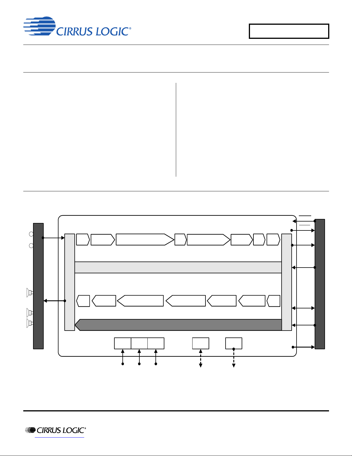
CS48LV12/13
Ultralow Power HD Voice Processors,
Featuring SoundClear® Technology
Overview of Features
• ASR Enhance™ automatic speech recognition (ASR)
preprocessing for increased ASR accuracy in noisy
• Complete easy-to-implement voice solution including all
essential voice, audio, and speech DSP features for
flagship smartphones, tablets, and computing products
• SoundClear Voice™ noise reduction, echo cancellation,
and voice enhancement
• RAPID2™ GUI-based diagnostic and tuning tool for ease
of design-in
• Media postprocessing support
—Integrated Cirrus Logic playback enhancement for
speakers and headphones
—Optional Dolby® and DTS® playback enhancement
1. Use of TrulyHandsfree-, Dolby-, or DTS-supported features requires the existence and proof of a valid license agreement with the
corresponding company to be able to use or distribute its technology in any finished end-user or ready-to-use final product.
environments
• Voice activity detector (VAD) enables always-on speech
recognition
• TrulyHandsfree™ voice control by Sensory, Inc.
supported
• Powerful 130-MHz dual-MAC 32-bit DSP core
• Ultralow power consumption (core typically <8 mW @ 1 V
during narrowband call)
2
•I
S, I2C, SPI™ digital connectivity
1
http://www.cirrus.com
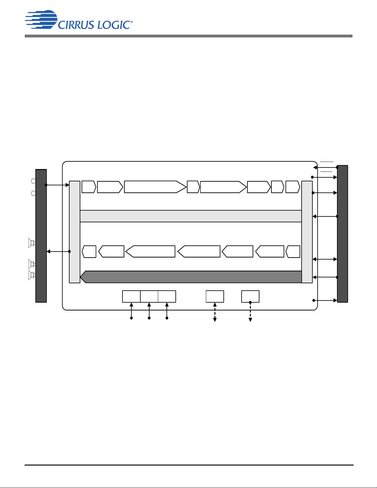
CS48LV12 Block Diagram
Copyright Cirrus Logic, Inc. 2014
(All Rights Reserved)
DS1057F1
FEB ‘14
Page 2
Codec
Ho st
PGA
Noise
Reduction
Acoustic Echo Canceller
Residual Echo Suppressor
NLP
Spectrally Matched
Comfort Noise
Dynamic
FlexEQ
ALC
PGA
Codec Port
Host Port
Full-Duplex Control + Vo ice Activit y Detect ion + Double-Talk Detection
PGA
Comfort
Noise
Automatic Volume
Control
Auto matic Level
Control
Dynamic
FlexEQ
Noise
Reduction
PGA
GND V
D
V
L
BUSY PLL/ClkMgr
I2S
Raw
PCM
I2S
Clean
PCM
I2S
Clean
PCM
I
2
S
Raw
PCM
Near
End
Far
End
Advanced Media Processor
SoundClear ASR Enhance™
SPI/I2C
RESET
Optional Voice Processing Featu res
Optional Postprocessing Features
Voice Activity
Detecto r
SoundClear
ASR Enhance™
Senso ry In c.
TrulyHandsfree™ Voice Control
Dolby Laboratories, Inc. Audio Postprocessing Algo rithms
DTS, Inc. Audio Postprocessing Algorithms
SoundClear Voice™ Features
• Flexible and tunable enabling freedom in product ID,
transducer placement and selection
• Robust proprietary algorithms assure consistent
performance across diverse sound environments and
off-axis
• Ambient-aware technologies constantly compensate for
changing noise types and level and varying product
positioning
• HD voice/wideband and narrowband support
• Supports handset, tablet, laptop, and speakerphone
single and multiple microphone configurations
• Conference room–grade AEC plus nonlinear residual
echo suppressor for superior full-duplex speakerphone
operation without echo
• Tx and Rx noise elimination
• Automatic volume control for both Tx and Rx
• Ambient-aware volume control compensates for variation
compensates variations in talker level, proximity, and
orientation
in Rx voice level and near-end noise level
• Tx and Rx comfort noise generators provide natural,
smooth transitions between single-talk Rx, single-talk Tx,
double-talk, and silent states
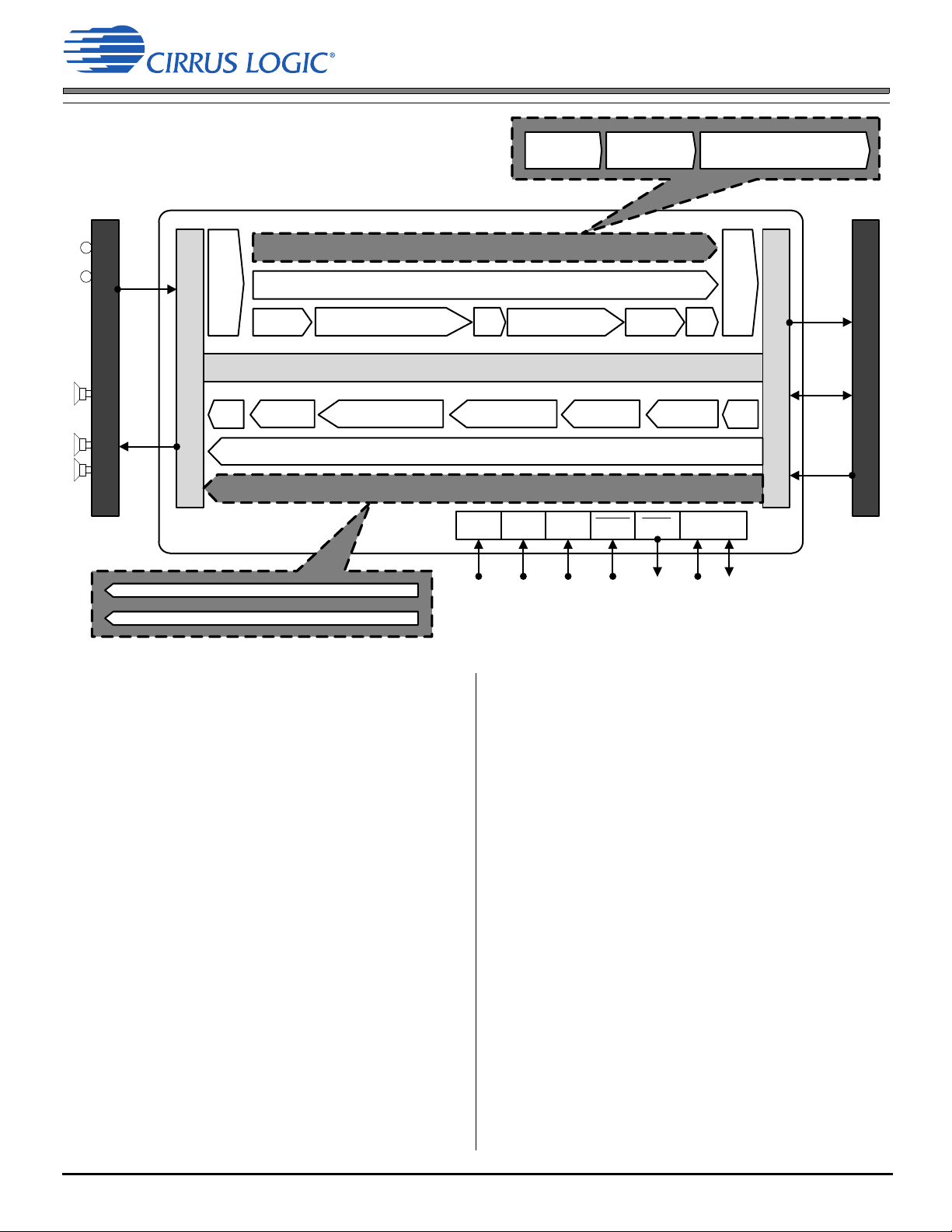
CS48LV13 Block Diagram
• Tx spectrally matched comfort-noise generator samples
and synthesizes ambient noise for more transparent talk
state transitions
• Tx and Rx parametric EQ simplifies carrier and industry
compliance, achieving natural sound and compensating
for transducer limitations
—Up to four concurrent Tx and four concurrent Rx filters
—Eight different filter types can be combined to achieve
exact requirements
—Each filter has tunable frequency, gain, and Q or
bandwidth
enables automatic real time tuning for improved
• Ambient-aware dynamic parametric EQ for Tx or Rx
intelligibility and to compensate for transducer
characteristics; responds to
—Tx or Rx stream amplitude
—Near-end ambient noise level
—User controls
• Rx compander for optimal speaker output level
• Mixed and mismatched microphone compensation
• Automatic calibration for up to ±6-dB sensitivity variation
• Compensation for microphone phase differences
DS1057F1 2
Page 3
Cirrus Logic Speech Features
(CS48LV13 Only)
• ASR Enhance preprocessor for ASR engines
—Improves speech command recognition of ASR
engines in noisy environments
—Can be applied with VAD described below and optional
TrulyHandsfree voice control and/or cloud based ASR
Optional Speech Features Supported
(CS48LV13 Only)
• Sensory TrulyHandsfree voice control
• Complete always-on local ASR solution
—Ultralow power always-on Cirrus Logic voice detection
(VAD)
—ASR Enhance pre-processor increases ASR accuracy
in noisy conditions
—TrulyHandsFree voice trigger and voice command
1
Audio Playback Features
• Full complement of Cirrus Logic audio-processing
algorithms preintegrated to enhance mono or stereo
playback over speakers or headphones
—Virtual surround
—Bass enhancement
—Bass virtualization
—Parametric EQ
—Multiband compressor
• Graphical interface for selection and tuning of algorithms
Optional Audio Playback Features Supported
(CS48LV13 Only)
• Dolby® postprocessing (enhancement and virtualization)
• DTS® postprocessing (enhancement and virtualization)
• Headphone and speaker playback support
1
Applications
The CS48LV12/13 provides a complete voice, audio
playback and speech preprocessing solution for
smartphone, tablet, laptop, headphone/headset, and
speaker/speakerphone applications. They are optimized
for devices where pristine voice quality and echo-free,
full-duplex communication is required, especially under
conditions of adverse noise and where space and power
are limited.
1.Use of TrulyHandsfree-, Dolby-, or DTS-supported features requires the existence and proof of a valid license agreement with the corresponding
company to be able to use or distribute its technology in any finished end-user or ready-to-use final product.
3 DS1057F1
Page 4

General Description
The CS48LV12 and CS48LV13 ultralow power voice processors feature Cirrus Logic’s patented SoundClear® technology
to provide a new standard in HD Voice quality performance, functionality, and cost effectiveness. These ICs provide a total
voice processing solution for handset and hands-free communications that deliver best-in-class noise reduction, echo
cancellation, and speech recognition. The CS48LV12 and CS48LV13 can enable advanced features including always-on
voice trigger, command recognition, ASR pre-processing, and audio enhancement. Innovative single and multi-mic
algorithms with intelligent speech tracking and noice elimination assure optimal user experience in the most challenging
and dynamic noise environments and deliver superior performance despite varying speech levels, talker distance, or
product orientation.
The CS48LV12 and CS48LV13 feature an integrated media processor with built-in virtual surround, bass enhancement,
bass synthesis, multi-band compression, and parametric EQ algorithms to enrich music playback through wireless
speakers and headphones. All are tunable through a simple GUI. In addition, the CS48LV13 provides the option of adding
a Cirrus Logic proprietary Voice Activity Detector for always-on ASR capability and integrated TrulyHandsfree™ Voice
Control. Also available is Cirrus Logic’s ASR Enhance™ specialized preprocessor to enhance the accuracy of any ASR
(Automatic Speech Recognition) engine under noisy conditions. An expanded menu of third-party media playback
algorithms from Dolby and DTS can also be integrated. Powerful real-time diagnostic and tuning tools combined with
specialized labs and a global applications support network assure ease of design, optimal performance, and achievement
of network and industry compliance.
DS1057F1 4
Page 5
1 Documentation
1 Documentation
This document describes the CS48LV12 and CS48LV13 HD voice processors. When evaluating or designing a system
around the CS48LV12/13 processors, use this document in conjunction with the documents listed in Table 1-1.
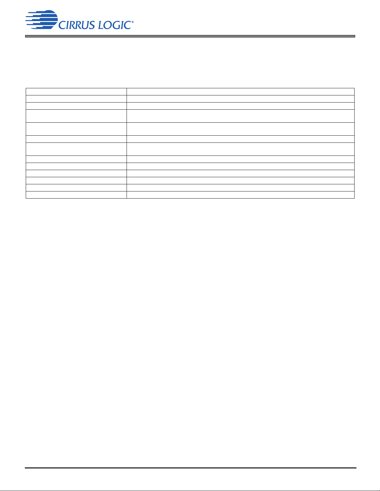
Table 1-1. CS48LV12/13 Related Documentation
Document Name Description
CS48LV12/13 Data Sheet This document
RAPID2
DSPComposer
CS48LV12/13
CS48L10 Hardware User’s Manual Includes detailed system design information including typical connection diagrams and boot
CRD48L10 4in4out Board Manual Manual for development and evaluation board for CS48L10/L11/LV12/LV13
Micro-condensers User’s Guide Instructional manual for using Micro-condenser for creating microcode and flash image for
AN344 Firmware User’s Manual for CS48L10/L11/LV12/LV13
AN344CBE Applications note for Cirrus Bass Enhancement (CBE) Module
AN344CBV Applications note for Cirrus Bass Virtualization (CBV) Module
AN344CVT Applications note for Cirrus Virtualization Technology (CVT)
AN344EQ Applications note for Cirrus Equalization (EQ) Module
AN344TC Applications note for Tone Control Post-processor Module
™ User’s Guide Instructional manual for using the RAPID2 tool for voice processing diagnostics and tuning
™ User’s Manual for
Manual for using the CS48LV12/13 version of DSP composer™ tool for post-processing
configuration and tuning
procedures applicable for CS48L10/L11/LV12/LV13
embedded systems applications
The primary scope of this document is to provide the hardware specifications of the CS48LV12/13 family of devices. These
include hardware functionality, characteristic data, pinout, and packaging information. The intended audience includes
system PCB designers, MCU programmers, and quality-control engineers.
2 Overview
The CS48LV12 and CS48LV13 products are based on Cirrus Logic 32 bit fixed point DSP's which feature the ultralow
power, tiny foot print, high performance and low cost that is required by today's mobile voice communication products. For
ease of implementation and high computational efficiency, each product includes an embedded software package highly
optimized for the DSP. Designed into each product is the ability to support multiple modes and configurations that match
an array of product use models for smartphones, tablets, and mobile computing devices as well as a variety of consumer
and automotive products with hands-free communication features.
The CS48LV12 incorporates Cirrus Logic SoundClear technology to perform all voice processing functions typically
required in handset and hands-free products including noise reduction, echo cancellation, and a comprehensive set of
voice enhancement capabilities. SoundClear technology uses proprietary algorithms to decipher spatial and spectral
characteristics of both the Rx (far-end) and Tx (near-end) digital voice streams and categorize various types of noise and
speech, removing noise and competing talkers while automatically adjusting for SPL changes, changes in product position
and orientation, and ongoing environmental changes. Other SoundClear modules monitor talk status (single Tx, single Rx,
silence, double-talk), cancel echo, suppress residual echo, and inject comfort noise if required to achieve natural,
consistent, full-duplex, echo-free conversation, in both hand-set and hands-free modes.
The CS48LV12 also includes integrated media processing capabilities to enhance audio playback over internal speakers
or attached devices such as speakers and headphones.
The CS48LV13 includes all the voice and media processing capabilities as well as ASR pre-processing (ASR Enhance)
to remove noise that limits ASR accuracy and reliability. It also includes a specialized Voice Activity Detector (VAD) that
enables the CS48LV13 to remain in a very low power "always-on" state until the VAD detects human speech in the
proximity of a microphone. This feature is typically used in conjunction with a local ASR solution such as the CS48LV13's
optional Sensory TrulyHandsfree voice control.
The CS48LV13 also supports several optional features requiring third party licenses:
• Sensory, Inc. TrulyHandsfree voice control
• Dolby, Inc. media playback enhancement algorithms
• DTS, Inc. media playback enhancement algorithms
5 DS1057F1
Page 6
Codec
SoC or Application Processor
PGA
Noise
Reduction
Acoustic Echo Canceller
Residual Echo Suppressor
NLP
Spectrally Matched
Comfort Noise
Dynamic
FlexEQ
ALC PGA
Codec Port
Host Port
Full-Duplex Control + Voice Activity Detection + Double Talk Detection
PGA
Comfort
Noise
Automatic Volume
Control
Automatic Level
Control
Dynamic
FlexEQ
Noise
Reduction
PGA
Media Processor
GND V
D
V
L
Debug MCLK
I2S
Raw
PCM
I2S
Clean
PCM
RESET
BUSY
I
2
S
Clean
PCM
CLK
SPI/I
2
C
I
2
S
Raw
PCM
INT
Near
End
Far
End
Optional
2.1 Licensing
A key feature of both products that enables ease of implementation, quick time to market and performance optimized to a
particular ID is the RAPID2 diagnostic and tuning tool. This Microsoft Windows® based tool provides GUI based
monitoring and control of all critical SoundClear parameters as well as system level measurements and statistics. RAPID2
tool features are described in Section 3.16.
2.1 Licensing
Licenses are required for any third-party audio-processing algorithms, including but not limited to Sensory, Inc.
TrulyHandsfree™ and Dolby and DTS postprocessing solutions provided for the CS48LV12/13. A Cirrus Logic royalty free
license is also required to distribute product containing the CS48LV12 or CS48LV13 embedded software packages
required for functionality described in this data sheet. Contact your local Cirrus Logic Sales representative for more
information.
3 Functional Description
Figure 3-1. CS48LV12 Block Diagram
DS1057F1 6
Page 7

Codec
Host
PGA
Noise
Reduction
Acoustic Echo Canceller
Residual Echo Suppressor
NLP
Spectrally Matched
Comfort Noise
Dynamic
FlexEQ
ALC
PGA
Codec Port
Host Port
Full-Duplex Control + Vo ice Activit y Detect ion + Double-Talk Detection
PGA
Comfort
Noise
Automatic Volume
Control
Auto matic Level
Control
Dynamic
FlexEQ
Noise
Reduction
PGA
GND V
D
V
L
BUSY PLL/ClkMgr
I2S
Raw
PCM
I2S
Clean
PCM
I2S
Clean
PCM
I
2
S
Raw
PCM
Near
End
Far
End
Advanced Media Processor
SoundClear ASR Enhance™
SPI/I2C
RESET
Optional Voice Processing Featu res
Optional Postprocessing Features
Voice Activity
Detecto r
SoundClear
ASR Enhance™
Senso ry In c.
TrulyHandsfree™ Voice Control
Dolby Laboratories, Inc. Audio Postprocessing Algo rithms
DTS, Inc. Audio Postprocessing Algorithms
3.1 Cirrus Logic 32-bit DSP Core
Figure 3-2. CS48LV13 Block Diagram
3.1 Cirrus Logic 32-bit DSP Core
The core is a high-performance, 32-bit, fixed-point DSP that is capable of performing two multiply-and-accumulate (MAC)
operations per clock cycle. The core has eight 72-bit accumulators, four X- and four Y-data registers, and 12 index
registers. It can operate up to 130 MHz, depending on mode and concurrency requirements, but it may also operate at low
speed to support specialized low-power modes, such as always-on voice wake.
The DSP core is coupled to a flexible DMA engine. The DMA engine can move data between peripherals such as the
multi-channel serial audio port, or any DSP core memory, without the intervention of the DSP. The DMA engine off-loads
data move instructions from the DSP core, leaving more MIPS available for signal-processing instructions.
3.2 Processing Groups
Providing consistent high-quality Tx and Rx voice streams in constantly changing environments requires a complex data
flow with constant interaction between various functional modules. While the actual data flow is more complex and not
linear, the architecture can be approximated as a set of in-line processing groups or chains that operate in different modes
depending on the current use model as follows.
CS48LV12:
1. Tx Voice DSP Chain
2. Rx Voice DSP Chain
3. Voice DSP Control and Detection
4. Audio Playback DSP Chain
7 DS1057F1
Page 8
PGA
Noise
Reduction
Acoustic Echo Canceller
Residual Echo Suppressor
NLP
Spectrally Matched
Comfort Noise
Dynamic
FlexEQ
ALC PGA
3.3 Tx Voice DSP Chain
The CS48LV13 includes two additional processing groups:
5. Speech DSP Chain
6. Advanced Audio Playback DSP Chain
Cirrus Logic provides two specialized tools for controlling and tuning the various processing groups. For voice- and
speech-related processing groups, the RAPID2 tool provides real-time analysis and tuning of all parameters. For
audio-playback chains, a specialized version of the DSP Composer tool is used for real-time control and tuning.
Each group may operate in more than one mode. Typically, smartphones have three or more operating modes:
a) Handset mode using processing Groups 1, 2, and 3
b) Speakerphone mode using processing Groups 1, 2, and 3
c) Media playback mode using processing Group 4 or 6
d) ASR mode using process using Group 5
Each mode may have tuning variations; for example, handset mode may include default tuning (using integrated
microphones and receiver), pass-through tuning for BT accessories, which perform their own voice processing and wired
headset tuning.
Tablets may have a single mode, similar to Speakerphone Mode, or may have multiple modes using different microphones
and processing, depending on their orientation and desired use model, such as portrait, landscape, handheld, on stand,
personal or group. Similarly, other applications may have a single or multiple modes using one or more processing groups.
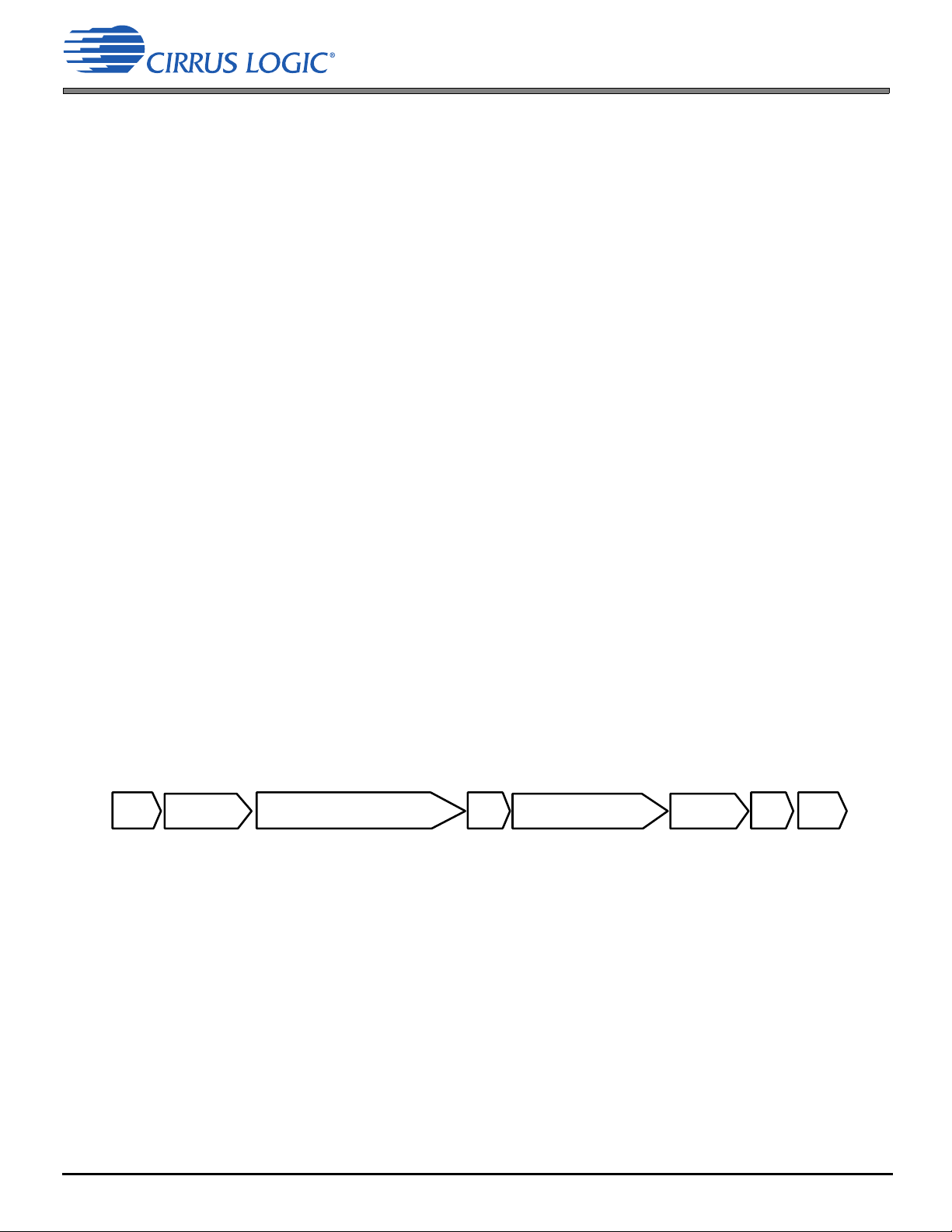
3.3 Tx Voice DSP Chain
The Tx Voice DSP Chain accepts raw PCM voice data from one or two microphones and uses this data, along with any
incorporated spatial information, to remove undesired noise and competing speech while preserving voice integrity. It also
includes AEC and residual echo suppression functions to remove echo. In combination with the Voice DSP Control and
Detection and Rx Voice DSP Chain groups, it manages full-duplex operation. A number of additional voice processing
blocks are included to provide a natural, intelligible, and consistent PCM voice stream.
Fig. 3-3 is a simplified diagram of the Tx Voice Chain. The start of the chain is fed by one or two voice PCM streams
originating from the voice microphones and arriving on one of the CS48LV12/13’s two I
The output of the chain, Tx Out, is transmitted out of one of the two I
2
S DAO outputs (typically DAO_1), typically a host
2
S DAI inputs (typically DAI_2).
processor, applications processor, or system on a chip (SoC), which then sends the stream to a digital baseband or other
network processor.
Figure 3-3. Tx Voice DSP Chain
3.4 Programmable Gain Amplifiers (PGAs)
One set of PGAs controls the level of the input streams from the mic and another PGA at the output of the chain controls
the level of the output stream (Tx Out). The RAPID2 tool includes PGA level meters with clipping detectors can be used
to adjust PGA gain level to maintain maximum SNR without danger of clipping.
3.5 Noise Reduction
SoundClear Voice technology uses a variety of innovative techniques and algorithms to distinguish between desired
speech, undesired speech (competing talkers), and nonspeech, and then suppresses all but desired speech.
In a two-mic configuration, SoundClear Voice technology uses signature analysis techniques to distinguish and eliminate
noise and to preserve the vocal quality of speech. Also, a proprietary beam forming technology analyzes the aural space
around the user and classifies sounds, based on direction of arrival and proximity. It also makes real-time voice-tracking
DS1057F1 8
Page 9

3.6 Acoustic Echo Cancellation (AEC)
adjustments to compensate for changes in device orientation. This results in better off-axis performance than do traditional
techniques with fixed acceptance angles. The noise-reduction block uses highly adaptive spatial analysis, spectral
analysis, and audio classification to quickly adjust for changes in audio environment and talker position.
Simple adjustments made through the RAPID2 tool allow the noise reduction block to be optimized for a variety of
microphone spacing and placements. Tightening standards on signal-to-noise-level improvement (SNRI) and voice quality
require careful balance to assure compliance and quality user experience. The RAPID2 tool provides the granularity of
control required to optimize user experience and compliance.
3.6 Acoustic Echo Cancellation (AEC)
In principle, the AEC works by recognizing the Rx signal that reappears, with some delay, in the Tx signal being processed
for transmission. Before transmission, the echo is removed by subtracting or canceling it out. In reality, canceling all
perceptible echo while maintaining full-duplex communication requires a complex set of monitoring control and digital DSP
algorithms. The CS48LV12/13’s AEC in combination with the Voice DSP Control and Detection group can provide
conference room–grade speakerphone performance within the performance constraints of the transducers used.
However, achieving high quality, full-duplex, echo-free performance in both handset and handsfree/speakerphone modes
requires conscientious system-level attention before completing component selection and design. Contact your Cirrus
Logic sales representative regarding available technical support early in the product-design process.
3.6.1 Residual Echo Suppressor/Nonlinear Processor
These blocks identify and suppress any nonlinear echo components not canceled by the AEC. The residual components
include distortion commonly introduced by small transducers, such as those used in mobile devices and is critical to
achieving a clean-sounding echo-free Tx voice stream.
3.7 Spectrally Matched Comfort Noise Generator (CNG)
Full-duplex communication can be classified into four possible states:
• Silence (neither the near- nor the far-end talker is speaking)
• Single-Talk Rx (only the far-end talker is speaking)
• Single-Talk Tx (only the near-end talker is speaking)
• Double-Talk (both talkers are speaking simultaneously)
During the Single-Talk Rx state, the AEC suppresses the Rx signal to eliminate all echo when no near-end voice is
detected. This can cause the person on the far end to perceive modulation between hearing ambient far-end noise and
then silence. To avoid this, the CNG samples ambient noise, synthesizes it, and injects it into the Tx stream whenever
there is silence, providing the far-end listener with a more natural, constant audio experience.
3.8 Dynamic PEQ
Cellular providers and industry standards require that Tx frequency response conforms to a tight envelope. Furthermore,
compensating for transducers characteristics and achieving natural voice character may require significant parametric
equalization of the Tx voice stream. This block provides up to four concurrent filters, each of which can be defined as one
of eight different filter types that can be combined to achieve exact frequency response requirement. Each filter has
tunable frequency, gain, and Q or bandwidth. The following filter types are available: low pass, high pass, low shelf, high
shelf, band pass, peaking, notch, and all pass.
In addition to functioning as a traditional parametric equalizer, this block can be operated in Ambient Aware Mode, where
EQ settings are automatically adjusted in real time, based on either loudness or noise levels. This feature can be used to
improve intelligibility under noisy conditions or maintain natural sound over changing loudness levels.
The dynamic PEQ block is the same for both the Tx and Rx voice DSP chains.
9 DS1057F1
Page 10

PGA
Comfort
Noise
Automatic Volume
Control
Automatic Level
Control
Dynamic
FlexEQ
Noise
Reduction
PGA
3.9 Automatic Level Control (ALC)
3.9 Automatic Level Control (ALC)
Tx voice level can vary greatly based on talker loudness, product distance and orientation. By distinguishing between voice
and noise levels and adjusting Tx voice level accordingly, the ALC is able to maintain more consistent Tx voice loudness
without boosting noise in periods of silence. This improves far-end user experience and product performance when it is
held away from the mouth or off-axis.
3.10 Rx Voice DSP Chain
Figure 3-4. Rx Voice DSP Chain
Table 3-1 describes the functions in the Rx voice DSP chain.
Table 3-1. Rx Voice DSP Chain Descriptions
Function Description
Programmable gain
amplifiers (PGAs)
Noise reduction Similar function as Noise Reduction in Tx Voice Chain, but operating on more limited information, because the Rx
Dynamic (PEQ) This block is the same for both the Tx and Rx Voice DSP chains. See Section 3.8.
Automatic level control
(ALC)
Automatic volume control
(ALC)
Comfort noise generator
(CNG)
One set of PGAs controls the level of the input streams from the host downlink (Rx). Another PGA at the output of
the chain controls the level of the output stream (Tx Out). The RAPID2 tool includes PGA level meters with clipping
detectors that can be used to adjust PGA gain level to maintain maximum SNR without danger of clipping.
stream from the far-end uses a single channel and lacks the spatial information necessary to perform the high levels
of SNRI achieved by the multi-mic algorithms applied to the Tx stream. However, the Rx noise-reduction function
can significantly suppress far-end noise, especially stationary-type noises.
Rx voice level can vary greatly, based on the far-end talkers loudness and on the phone’s orientation. By
distinguishing between voice and noise levels and by adjusting Rx voice level accordingly, the ALC can maintain
more consistent Rx voice volume, without boosting noise during silent periods. This improves near-end user
experience and product performance when a far-end talker speaks softly or holds the phone away from their mouth.
As ambient noise level rises, it can be more difficult for the user to understand the caller, regardless of whether the
product is being used in handset or hands-free/speakerphone mode. The ALC block automatically adjusts receive
loudness, based on ambient noise level.
CNG is used to inject levels of synthesized noise into the Rx stream during periods of silence, so that the near-end
user avoids hearing noise modulation.
3.11 Voice DSP Control and Detection Group
The voice DSP control and detection group encompasses several functions related to managing the combined Tx and Rx
Voice DSP Chains. Key functions include full-duplex communication state control, voice detection, noise classification,
AEC, and residual echo-suppression control.
3.12 Audio Playback DSP Chain/Advanced Audio Playback DSP Chain
This chain consists of various audio postprocessing modules for enhancement of media playback. The modules have
multiple use modes for support of both integrated speakers and plug-in headphones. Both the CS48LV12 and CS48LV13
integrate the following Cirrus Logic algorithms:
• Virtual surround
• Bass enhancement
• Bass virtualization
• Parametric EQ
• Multiband compressor
A special version of Cirrus Logic® DSP Composer tool enables selection of the desired combination of algorithms and
their tuning.
Optionally, the CS48LV13 supports popular postprocessing algorithms from Dolby and DTS. A license agreement with
Dolby or DTS is required to use this feature. DSP composer support for these algorithms is also available.
DS1057F1 10
Page 11

3.13 Speech DSP Chain
3.13 Speech DSP Chain
The CS48LV13 includes Cirrus Logic ASR Enhance preprocessor that removes noise impacting ASR engine
performance. SoundClear ASR Enhance algorithms use specialized spatial NR techniques to improve command success
rate by accomplishing the following:
• Reducing near-end noise that masks speech pauses and otherwise interferes with accuracy
• Suppressing cross-talk from competing talkers in the vicinity
• Preserving voice spectral content
• Preventing phoneme degradation
• Using InstantAdapt™ noise adaption to avoid missed or truncated commands
The ASR Enhance preprocessor can be used to improve local ASR performance including the optional Sensory
TrulyHandsfree voice control as well as cloud based engines.
The CS48LV13 supports an optional speech chain, which can include the following functions:
• Cirrus Logic voice activity detector (VAD). This specialized VAD enables always-on ultralow-power voice trigger.
The VAD constantly monitors ambient sound while the CS48LV13 is in a very low power state. If it detects voice,
the VAD can trigger the supported Sensory TrulyHandsfree voice control engine running on the CS48LV13.
• Sensory TrulyHandsfree voice control. When the VAD has detected a voice, it can trigger TrulyHandsfree to detect
a predefined wake-up command. If it detects the proper command, it enters Voice-Command Mode to interpret any
command within its vocabulary. If the proper wake-up command is not detected, the device can return to its
always-on VAD mode.
3.14 On-chip DSP Peripherals
3.14.1 I2S Digital Audio Ports
3.14.1.1 I
Two DAI ports support PCM format with word lengths up to 32 bits and sample rates as high as 192 kHz. DAI_1 is typically
connected to a host processor, applications processor, or mobile SoC to receive Rx voice and audio data. DAI_2 is
typically connected to a codec or A/D streaming Tx voice or audio data captured from microphones. Both ports operate in
2
I
S slave clock mode using SCLK and LRCLK for bit-clock and word select. For voice (call) modes, both DAI ports use a
16-bit word length, a 8-KHz sample rate for narrowband calls, and 16-KHz sample rate for HD voice/wide-band calls. Rx
(downlink) requires one channel and Tx (requires one or two channels), depending on microphone/input mode. For
playback mode, other audio formats are supported, based on the content type and postprocessing algorithms applied.
3.14.1.2 I2S Digital Audio Output Port (DAO)
Two DAO ports support PCM format with word lengths up to 32 bits and sample rates as high as 192 kHz.
DAO_1 is typically connected to a host processor, applications processor or mobile SoC to transmit Tx voice and audio
data. DAO_2 is typically connected to a codec, D/A, or digital amp streaming Rx voice or audio data out to transducers
such as mobile phone receiver, speakers, or headphone. Both ports operate in I
LRCLK for bit clock and word select. For voice (call) modes both DAO ports will use a 16-bit word length, 8-KHz sample
rate for narrowband calls, and 16 KHz for HD voice/wide-band calls. For playback mode, other audio formats are
supported based on the content type and postprocessing algorithms being applied.
2
S Digital Audio Input Ports (DAI)
2
S slave clock mode using SCLK and
3.14.2 Serial Control Port (I2C or SPI)
The on-chip serial control port is capable of operating as slave in either I2C or SPI modes. Slave operation is chosen by
a mode select pin when the CS48LV12/13 comes out of reset. The serial clock pin can support frequencies as high as
25 MHz in SPI mode.
The slave SPI clock speed must always be (DSP Core Frequency/2).
11 DS1057F1
Page 12

3.15 Power Management
The serial control port also includes a pin for flow control of the communications interface (BUSY/I2C_SELECT) and a pin
to indicate when the DSP has a message for the host (INT
).
3.14.3 PLL-based Clock Generator
The low-jitter PLL generates integer or fractional multiples of a reference frequency, which are used to clock the DSP core
and peripherals. Through a second PLL divider chain, a dependent clock domain can be output on the DAO port for driving
audio converters. The CS48LV12/13 defaults to running from the external reference frequency and is switched to use the
PLL either through a boot command from the host or by the firmware running on the DSP.
3.15 Power Management
Several control registers and bits provide independent power down control of the RAM, ROM, PLL and internal clock
domains, allowing operation in select applications with minimal power consumption. Each RAM bank (4 K word) and each
ROM bank (8 K word for code, and 4 K word for data) can be powered on or off individually. After a hardware reset, all the
memory banks are powered on.
The Host in the system can initiate a low-power mode for the DSP core to conserve system power when audio processing
is not required. The firmware API provides different levels of low-power mode, which allows each system to customize the
power consumption and wake-up protocol to its needs.
3.16 RAPID2™ Real-Time Diagnostic and Tuning Tool
This real-time interactive GUI-based program provides both control and monitoring of all critical SoundClear Voice DSP
functions. It enables users to optimize algorithmic performance to match design characteristics such as transducer type
and placement, mechanical and electrical design, and acoustic properties. It is both a system level diagnostic and tuning
tool that is used to achieve performance goals as well as industry, carrier, and OEM compliance. Its capabilities include:
• Meter monitoring including peak and clip detection for:
• Mic inputs
• Tx line out
• Rx line in
• Rx speaker out
• Dual-axis tickertape graphic monitoring
• AEC performance
• AEC input and AEC output
•Audio mode
• Mic 1 and mic 2
• Speaker out
• Line in and line out
• Automatic system-level measurements
• Bulk delay
• ENR—Echo to near-end ratio
• ERLE—Echo return loss enhanced
• Statistical measurements included
• Channel noise levels
• Channel amplitude levels
• Clip occurrences
• Real-time control of all SoundClear parameter sets
• All programmable gain amplifiers (Tx in, Tx out, Rx in, Rx out)
DS1057F1 12
Page 13

• Multi-mic noise reduction
• Single-mic noise reduction
• Audio detection and classification
• AEC, including path-change detection
• Nonlinear residual echo suppression
• Tx and Rx automatic level control
• Tx and Rx parametric EQ (with graphical interface)
• Rx automatic volume control
• Speaker out compander
• Double-talk detection
• Voice activity detection
• Tx and Rx comfort noise generation
4 Characteristics and Specifications
4.1 Absolute Maximum Ratings
4 Characteristics and Specifications
GND = 0 V; all voltages with respect to ground.
Parameters Symbol Min Max Units
DC Power Supply DSP Core/Memory/PLL
Serial/Control
Input Current
External Voltage Applied to Digital Input
Storage Temperature T
1.Any pin except supplies. This value is characterized not tested.
2.The maximum over/under voltage is limited by the input current.
1
2
VD, VPLL
VL
I
in
V
IND
stg
–0.3
–0.3
—10mA
–0.3 VL * 1.2 V
–65 +150 °C
WARNING: Operation at or beyond these limits can result in permanent damage to the device.
4.2 Recommended Operating Conditions
GND = 0 V, all voltages with respect to ground.
Parameters Symbol Min Max Units
DCPower Supply
Ambient Temperature Commercial
Ambient Temperature Automotive
Junction Operating Temperature
External Voltage Applied to Digital Input V
1.VL must rise before or simultaneously with VD and VPLL.
Core/Memory/PLL
I/O interface
1
VD, VPLL 0.90 1.32 V
1
VL 1.62 3.6 V
T
T
T
A
A
J
IND
0+70C
–40 +105 C
–40 +110 C
–0.3 VL * 1.1 V
1.5
4.0
V
V
13 DS1057F1
Page 14

4.3 Power Supply Characteristics—1.0 V Power Dissipation
4.3 Power Supply Characteristics—1.0 V Power Dissipation
Test Conditions (unless otherwise specified): VD,VPLL=1.0 V, VL=1.8 V, GND = 0 V; all voltages with respect to GND.
T
=+25°C.
A
Parameters Typical Units
Core and I/O Operating
1
VD + VPLL
VL 0.8 mA
RESET Active
3
VD + VPLL
VL
Hibernate Mode
4
VD + VPLL
VL
Sleep Mode
5
VD + VPLL
VL 0.147
1.Characterized with O/S and MP3 decode running at 80 MHz, 6 MHz CLOCK driving PLL, MCLK slave, I²S data delivery.
2.VPLL exists only on the QFN package.The WLCSP package combines VD and VPLL into a single VD pin.
3.Characterized with RESET driven low, CLOCK pin of CS48LV12/13 gated off, and all inputs to CS48LV12/13 driven to VL.
4.The low-power mode used in this example is Hibernate mode. Characterized with DSP core halted, all memory banks powered down, PLL powered
down, and all internal clock domains gated off, CLOCK pin of CS48LV12/13 gated off, and all inputs to CS48LV12/13 driven to VL.
5.The low-power mode used in this example is Sleep mode. Characterized with DSP core halted, all memory banks powered up, PLL powered down,
all internal clock domains gated off, CLOCK pin of CS48LV12/13 gated off, and all inputs to CS48LV12/13 driven to VL.
2
2
2
2
9.5 mA
1.8 mA
1.5
11
0.147
45 A
A
A
A
A
4.4 Power Supply Characteristics—1.2 V Power Dissipation
Test Conditions (unless otherwise specified): VD,VPLL=1.2 V, VL=1.8 V, GND = 0 V; all voltages with respect to GND.
T
=+25°C.
A
Parameters Typical Units
Core and I/O Operating
1
VD + VPLL
VL 0.8 mA
RESET Active
3
VD + VPLL
VL
Hibernate Mode
4
VD + VPLL
VL
Sleep Mode
5
VD + VPLL
VL 0.147
1.Characterized with O/S and MP3 decode running at 80 MHz, 6 MHz CLOCK driving PLL, MCLK slave, I²S data delivery.
2.VPLL exists only on the QFN package. The WLCSP package combines VD and VPLL into a single VD pin.
3.Characterized with RESET driven low, CLOCK pin of CS48LV12/13 gated off, and all inputs to CS48LV12/13 driven to VL.
4.The low-power mode used in this example is Hibernate mode. Characterized with DSP core halted, all memory banks powered down, PLL powered
down, and all internal clock domains gated off, CLOCK pin of CS48LV12/13 gated off, and all inputs to CS48LV12/13 driven to VL.
5.The low-power mode used in this example is Sleep mode. Characterized with DSP core halted, all memory banks powered up, PLL powered down,
all internal clock domains gated off, CLOCK pin of CS48LV12/13 gated off, and all inputs to CS48LV12/13 driven to VL.
2
2
2
2
12.0 mA
3.3 mA
1.5
17
0.147
75 A
A
A
A
A
DS1057F1 14
Page 15

4.5 Thermal Characteristics
4.5 Thermal Characteristics
Parameter Symbol Min Typ Max Units
QFN junction-to-ambient thermal impedance
WLCSP junction-to-ambient thermal impedance
QFN junction-to-ambient thermal impedance
WLCSP junction-to-ambient thermal impedance
1. To calculate the die temperature for a given power dissipation:
T
= Ambient temperature + [ (Power Dissipation in Watts) * ja ]
j
2.Four-layer board is specified as a 76 mm X 114 mm, 1.6 mm thick FR-4 material with 1-oz. copper covering 20% of the top and bottom layers and
0.5-oz. copper covering 90% of the internal power plane and ground plane layer
3.Two-layer board is specified as a 76 mm X 114 mm, 1.6 mm thick FR-4 material with 1-oz. copper covering 20% of the top and bottom layers.
1,2
1,2
1,3
1,3
4-layer board
4-layer board
2-layer board
2-layer board
JA
JA
JA
JA
—28 —°C/Watt
—47 —°C/Watt
—85 —°C/Watt
—89 —°C/Watt
4.6 Digital Interface Specifications and Characteristics
Test Conditions (unless otherwise specified): VL = 1.8 V–3.3 V, VD = 1.0 V–1.2 V; GND = 0 V; TA=+25°C.
Parameters Test Conditions Symbol Min Typ Max Units
Input leakage current
Internal weak pull-up
Input capacitance
VL logic
High-level output voltage
Low-level output voltage
High-level output voltage
Low-level output voltage
High-level input voltage — — V
Low-level input voltage — — V
1.Specification is per pin, and does not include current through pull-up.
2.The effective pull-up value decreases (more current is provided) with increased VL.
3.This value is by design and not a tested parameter.
4.This value tested with 2-mA drivers enabled on pins.
1
2
3
4
4
4
4
—— Iin— — 500 nA
—— — 15—60k
—— — —10—pF
VL = 3.3 V IOH = 2 mA V
VL = 3.3 V IOL = 2 mA V
VL = 1.8 V IOH = 1 mA V
VL = 1.8 V IOL = 1 mA V
OH
OL
OH
OL
IH
IL
VL–0.4 — — V
— — 0.20•VL V
VL–0.4 — — V
— — 0.20•VL V
0.76•VL — — V
— — 0.30•VL V
Figure 4-1. Internal Weak Pull-up
15 DS1057F1
Page 16
T
rstl
T
rstsu
T
rsthld
INT
BUSY/I2C_SELECT
All supplies at
recommended
operating values.
VD,
VPLL,
VL
RESET
RESET
T
rst2z
T
rstl
T
rstsu
T
rsthld
INT
BUSY/I2C_SELECT
All Bidirectional
Pins
t
CLOCKh
T
CLOCK
CLOCK
t
CLOCKl
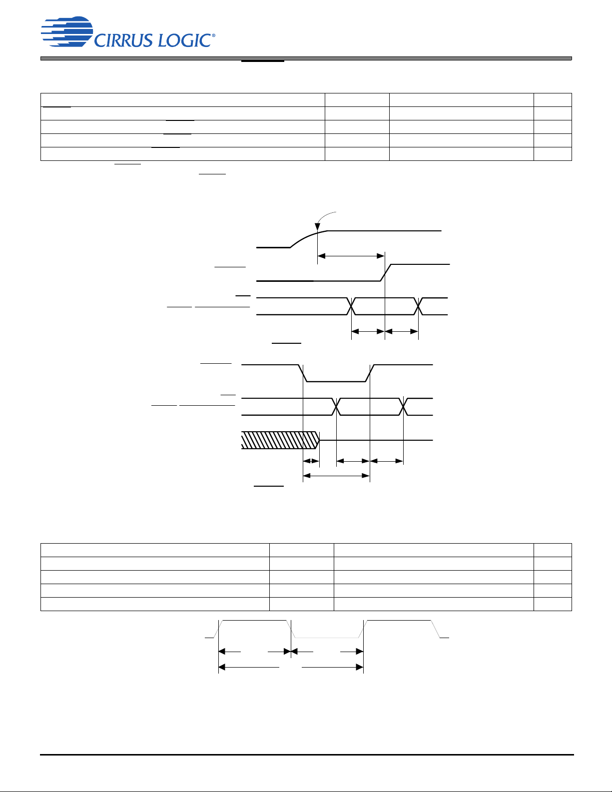
4.7 Switching Characteristics—RESET
4.7 Switching Characteristics—RESET
Parameter Symbol Min Max Unit
RESET
minimum pulse width low
All bidirectional pins high-Z after RESET
Configuration pins setup before RESET
Configuration pins hold after RESET
1.The rising edge of RESET must not occur before the power supplies are stable at their recommended operating values. In addition, for the
configuration pins to be read correctly, the RESET
1
low T
high T
high T
T
requirement must be met.
rstl
T
rstl
rst2z
rstsu
rsthld
1—s
— 100 ns
50 — ns
20 — ns
Figure 4-2. RESET Timing at Power-On
Figure 4-3. RESET
4.8 Switching Characteristics—CLOCK
Parameter Symbol Min Max Unit
External clock operating frequency F
CLOCK period T
CLOCK high time T
CLOCK low time T
Timing after Power is Stable
CLOCK
CLOCK
CLOCKh
CLOCKl
3.072 38.4 MHz
26 325 ns
45% · T
CLOCK
45% · T
CLOCK
55% · T
55% · T
CLOCK
CLOCK
ns
ns
DS1057F1 16
Figure 4-4. CLOCK Timing
Page 17
4.9 Switching Characteristics—Internal Clock
4.9 Switching Characteristics—Internal Clock
Parameter Symbol Min Typ Max Unit
Internal DCLK frequency
Internal DCLK frequency
1
(VD, VPLL = 1.2 V)
1
(VD, VPLL = 1.0 V) F
F
dclk
dclk
F
CLOCK/
F
CLOCK/
256 — 130 MHz
256 — 80 MHz
Internal DCLK period (VD, VPLL = 1.2 V) DCLKP 7.69 — 256/F
Internal DCLK period (VD, VPLL = 1.0 V) DCLKP 12.5 — 256/F
Cycle-to-cycle jitter on Internal DCLK or Mastered MCLK
1.After initial power-on reset, F
reconfigured for a new setting or the next RESET
2.This parameter is characterized with a VCO speed of 330 MHz.
dclk
= F
. After initial kick-start commands, the PLL is locked to max F
CLOCK
pulse.
2
——500—ps
and remains locked until PLL is
dclk
4.10 Switching Characteristics—Serial Control Port—SPI Slave Mode
Parameter Symbol Min Typical Max Units
CLK frequency
CS
falling to CLK rising t
CLK low time t
CLK high time t
Setup time MOSI input t
Hold time MOSI input t
CLK low to MISO output valid t
CLK falling to INT
CS
rising to INT falling t
CLK low to CS
CS
rising to MISO output high-Z t
CLK rising to BUSY
1.The specification f
communication port can be limited by the firmware application. Flow control using the BUSY
input data buffer. Maximum SPI clock speed is F
1
rising t
rising t
falling t
indicates the maximum speed of the hardware. The system designer should be aware that the actual maximum speed of the
spisck
/2. Before locking PLL, F
dclk
f
spisck
spicss
spickl
spickh
spidsu
spidh
spidov
spiirqh
spiirql
spicsh
spicsdz
spicbsyl
—— 25MHz
24 — — ns
20 — — ns
20 — — ns
5— —ns
5— —ns
—— 11ns
— — 20 ns
0— —ns
24 — — ns
—20 —ns
—3
dclk
= F
CLOCK
.
DCLKP+20 — ns
*
pin should be implemented to prevent overflow of the
CLOCK
CLOCK
ns
ns
17 DS1057F1
Page 18

BUSY/
I2C_ SELEC T
CS
CLK/SCL
MOSI
MISO/SDA
INT
0
12670
56
7
t
spi cs s
t
spi ck l
t
spi ck h
t
spi d su
t
spi d h
t
spi do v
A6 A5 A0 R/W MSB LSB
MSB LSB
t
spi csh
t
spi bsy l
t
spi irq l
t
spiirqh
f
spi sck
t
spi csd z
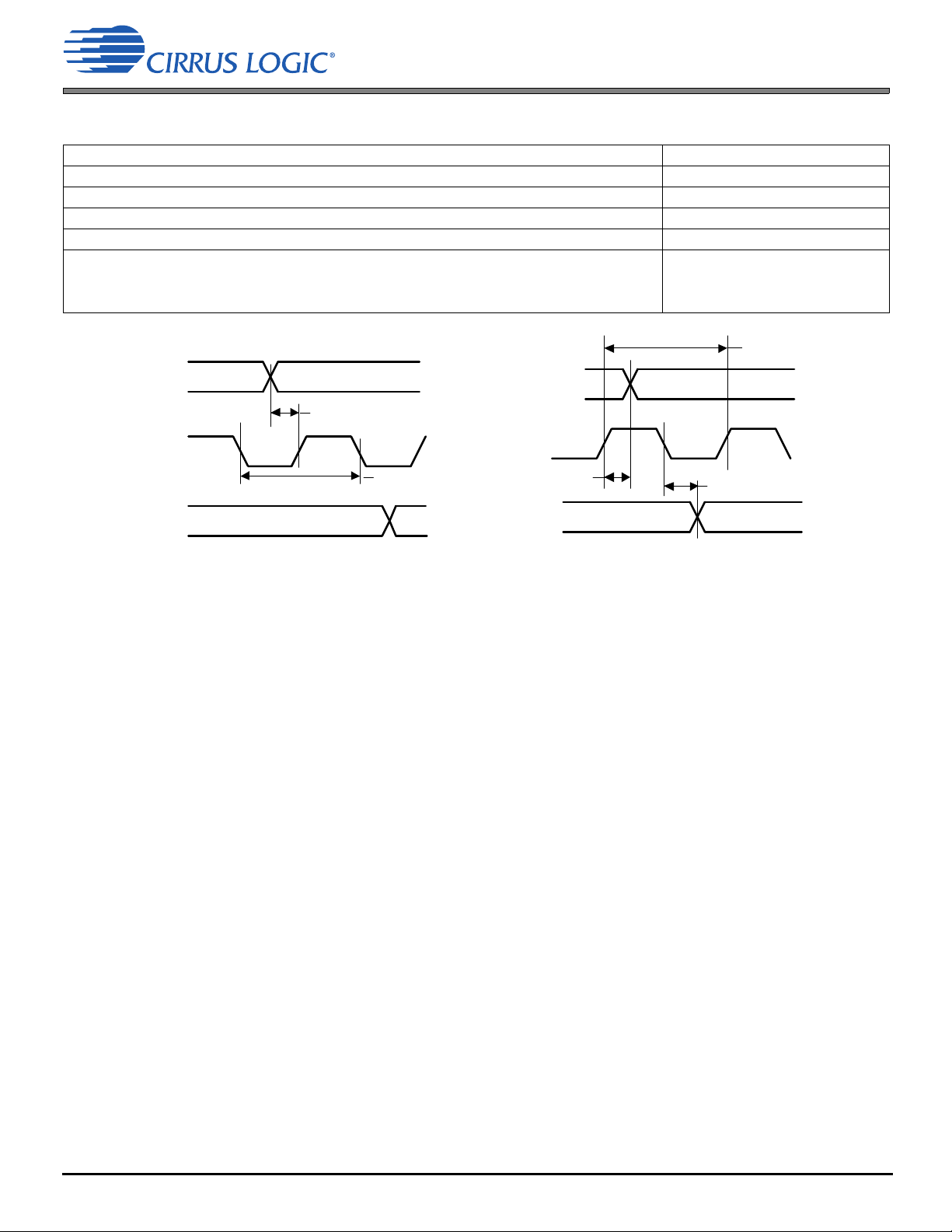
4.11 Switching Characteristics—Serial Control Port—I2C Slave Mode
Figure 4-5. Serial Control Port—SPI Slave Mode Timing
4.11 Switching Characteristics—Serial Control Port—I2C Slave Mode
Parameter Symbol Min Typical Max Units
SCL frequency
SCL low time t
SCL high time t
SCL and SDA rise time t
SCL and SDA fall time t
SCL rising to SDA rising or falling for START or STOP condition t
START condition to SCL falling t
SCL falling to STOP condition t
Bus free time between STOP and START conditions t
Setup time SDA input valid to SCL rising t
SDA input hold time after SCL falling t
SDA output hold time from SCL falling t
SCL falling to INT
NAK condition to INT
SCL rising to BUSY
1.The specification f
communication port can be limited by the firmware application. Flow control using the BUSY
input data buffer.
1
rising t
low t
low t
indicates the maximum speed of the hardware. The system designer should be aware that the actual maximum speed of the
iicck
f
iicckh
iicckcmd
iicstscl
iicstp
hddo
iicirqh
iicirql
iicbsyl
iicck
iicckl
r
f
iicbft
iicsu
iich
—— 400kHz
1.25 — — µs
1.25 — — µs
— — 75 ns
— — 75 ns
1.25 — — µs
1.25 — — µs
2.5 — — µs
3— —µs
100 — — ns
0— —ns
— — 18 ns
——3
—3*DCLKP + 20 — ns
pin should be implemented to prevent overflow of the
DCLKP + 40 ns
*
3*DCLKP + 20 — ns
DS1057F1 18
Page 19

BUSY/
I2C_SELECT
CLK/SCL
MISO/SDA
INT
01 67801 7
t
iicckl
t
iicckh
t
iicsutiich
A6 A0 R/W ACK
LSB
t
iicirqh
t
iicirql
8
ACK
MSB
t
iicstp
6
t
iiccbsyl
t
hddo
t
iicbft
t
iic st scl
t
iicckcmd
f
iicck
t
iicckcmd
t
iicf
t
iicr
DAI_SCLK
DAI_LRCLK
DAI_Dx
t
daislrts
t
daiclkp
DAI_SCLK
DAI_LRCLK
t
daisstlr
t
daidh
t
daiclkp
DAI_Dx
t
daidsu
4.12 Switching Characteristics—Digital Audio Slave Input Port
Figure 4-6. Serial Control Port—I2C Slave Mode Timing
4.12 Switching Characteristics—Digital Audio Slave Input Port
SCLK period T
SCLK duty cycle —4555%
Setup time DAI_Dx
Hold time DAI_Dx
Slave mode SCLK active edge to LRCLK transition t
1.All DAI data lines are timed relative to active edge of SCLK
19 DS1057F1
Parameter Symbol Min Max Unit
1
1
LRCLK transition to SCLK active edge t
Figure 4-7. DAI Port Slave Timing Diagram
daiclkp
t
daidsu
t
daidh
daisstlr
daislrts
40 — ns
10 — ns
5—ns
10 — ns
10 — ns
Page 20
SCLK
LRCLK
DAO_Dx
t
daoslrts
t
daosclk
SCLK
LRCLK
t
da osstl r
t
daosdv
t
daosclk
DAO_Dx
4.13 Switching Characteristics—Digital Audio Output Port
4.13 Switching Characteristics—Digital Audio Output Port
Parameter Symbol Min Max Unit
MCLK period T
MCLK duty cycle —4555%
DAO_SCLK period for Slave mode T
DAO_SCLK duty cycle for or Slave mode — 40 60 %
Slave Mode SCLK active edge to LRCLK transition t
LRCLK transition to SCLK active edge t
DAO_Dx delay from SCLK inactive edge t
daomclk
daosclk
daosstlr
daoslrts
daosdv
20 — ns
20 — ns
10 — ns
10 — ns
—11ns
Figure 4-8. Digital Audio Output (DAO) Port Timing, Slave Mode
DS1057F1 20
Page 21
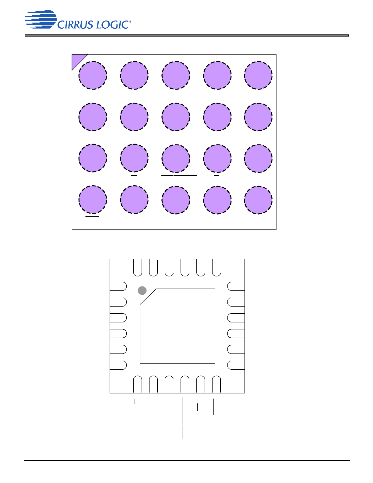
5 Pin Descriptions
Top-Down (Thr ough-Pac kage)View
20-Ball WLCSP Package
A4A3A2A1
B4B3B2B1
DAO_D1
DAI_D2 VD
VL
DAO_D2
C2C1
D2D1
C4C3
GND
CLK/SCL
DAI_D1
D4D3
MISO /SDA
DBCK
DBDA
MOSI
A5
B5
C5
SCL K
D5
LRCLK
MCLK
CLOCK
RESET
CSINT BUSY/I2C_SELECT
87
6
5
4
3
2
1
9
10
11 12
19
202122
23
24
13
14
15
16
17
18
Thermal Pad
Top -Down (Thr ough Package ) Vi ew
24-Pi n QFN Pac kage
VD
DAO_D2
DAI_D2
GND
DBDA
DBCK
VPLL
VL
BUSY/I2C_SELECT
INT
GND
MCLK
MOSI
DAO_D1
DAI _D 1
LRCLK
SCLK
CLOCK
MISO/SDA
CLK/SCL
CS
VL
VD
RESET
5 Pin Descriptions
21 DS1057F1
Page 22
5 Pin Descriptions
Pin Name CSP
Ball#
DAO_D1 A1 19 Digital Audio Data Output 1 (Host/Tx/Uplink)
DAI_D2 B3 20 Digital Audio Input 2 (Mic In)
DAO_D2 B4 21 Digital Audio Data Output 2 (Receiver/Speakers)
DAI_D1 A2 22 Digital Audio Data Input 1 (Host/Rx/Downlink)
SCLK A4 24 Digital Audio Clock
LRCLK A3 23 Digital Audio Clock
CLOCK A5 1 Reference Clock Input
MCLK B2 18 Master Audio Clock
MISO/SDA D3 8 Serial Control Data
MOSI D2 9 Serial Control Data
CLK/SCL D4 6 Serial Control Port Clock
CS
DBDA B1 17 Debug Serial Control Data
DBCK C1 13 Debug Serial Control Port Clock
RESET
INT
BUSY
I2C_SELECT
Thermal Pad — Thermal Pad (QFN package only)
/
VD B5 4,16 Digital Core and Memory Power
VPLL — 2 PLL Power
VL D5/ 5,14 Digital Interface Power
GND C5 3,15 Ground
C4 7 Serial Control Port Select
D1 12 Reset
C2 11 Interrupt (requires 10 K external pull-up resistor)
C3 10 Busy Indicator
QFN
Pin#
Pin Functions
• (O) DAO output 1 for two’s complement serial audio data
• (I) Two’s complement serial audio data input 2 (DAI_D2)
• (O) Two’s complement serial audio data output 2
• (I) DAI Input 1 for two’s complement serial audio data
• DAI serial audio bit clock
• (I/O) DAI Left/Right Clock (Frame Sync)
• (I) Reference clock for internal PLL
• (I/O) High-speed serial audio clock (no connect for most applications)
• (O) Serial data output for SPI slave mode
• (Open-Drain Bidir) Data for I²C serial control
• (I) Serial data input for SPI slave mode
• (I) Serial control clock for SPI slave mode
• (Open-Drain Bidir.)Serial control clock for I²C slave
• (I) Chip select for SPI slave mode
• (Open-Drain Bidir) Open-drain serial data for the I²C debug serial control port
• (Open-Drain Bidir.) Open-drain serial clock for the I²C debug serial control port
• (I) Active low. Registers are reset to default settings and boot mode selected
• (Open-Drain Output) Active low. Programmable interrupt output
• (Open-Drain Output) Active low. DSP busy signal output
• (I) Boot mode select 0 on rising edge of RESET
• (I) Power supply for the core and memory section
• (I) QFN package only. Power supply for PLL—tie to VD.
• (I) Sets voltage reference level for serial audio interfaces and SP
• (I) Ground reference
• (I) Thermal relief pad for optimized heat dissipation. This pad must be connected to GND.
(selects boot from I2C rather than the default SPI)
DS1057F1 22
Page 23

5.1 I/O Pin Characteristics
5.1 I/O Pin Characteristics
Input and output levels and associated power supply voltage are shown in Table 5-1. Logic levels should not exceed the
corresponding power supply voltage. Typical hysteresis for VL inputs is 250 mV.
. fdf
Table 5-1. I/O Pin Characteristics
Pin Name I/O
DAO_D1 I/O VL Programmable pull-up CMOS CMOS, with hysteresis
DAI_D2 I/O VL Programmable pull-up CMOS CMOS, with hysteresis
DAO_D2 I/O VL Programmable pull-up CMOS CMOS, with hysteresis
DAI_D1 I/O VL Programmable pull-up CMOS CMOS, with hysteresis
SCLK I/O VL Programmable pull-up CMOS CMOS, with hysteresis
LRCLK I/O VL Programmable pull-up CMOS CMOS, with hysteresis
CLOCK I VL — — CMOS, with hysteresis
MCLK I/O VL Programmable pull-up CMOS CMOS, with hysteresis
MISO/SDA I/O VL Programmable pull-up CMOS/open drain CMOS, with hysteresis
MOSI I/O VL Programmable pull-up CMOS CMOS, with hysteresis
CLK/SCL I/O VL Programmable pull-up CMOS/open drain CMOS, with hysteresis
CS
DBCK I/O VL Programmable pull-up CMOS/open drain CMOS, with hysteresis
DBDA I/O VL Programmable pull-up CMOS/open drain CMOS, with hysteresis
RESET
INT
BUSY
I2C_SELECT
/
I/O VL Programmable pull-up CMOS CMOS, with hysteresis
I VL Pull-up — CMOS, with hysteresis
O VL Programmable pull-up CMOS/open drain CMOS, with hysteresis
I/O VL Programmable pull-up CMOS/open drain CMOS, with hysteresis
Vol tag e
Reference
Internal
Ter minati on
Driver Receiver
23 DS1057F1
Page 24
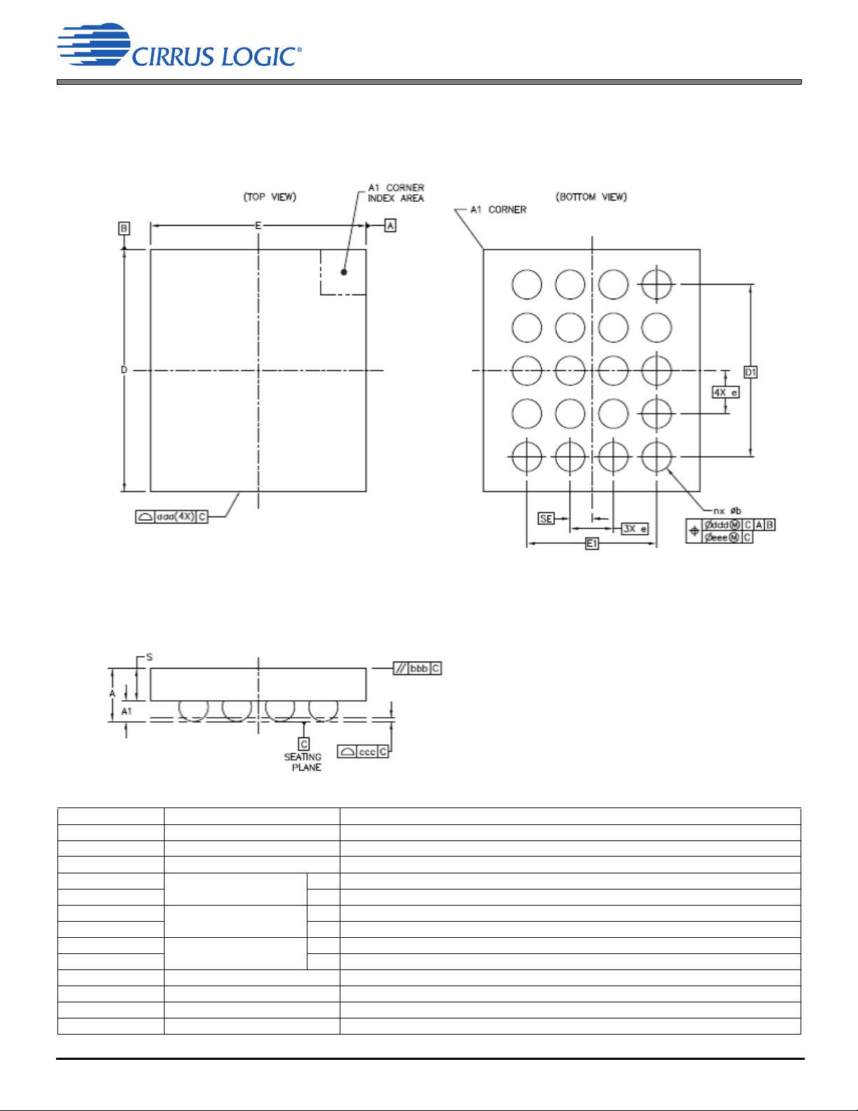
6 Package Dimensions
20-BALL WLCSP (2.25 mm x 2.0 mm Body) Package Drawing
A B C D
1
2
3
4
5
6 Package Dimensions
Table 6-1. WLCSP Package Dimension
Symbol Description Dimensions
A Total thickness 0.495 ±0.04
S Wafer thickness 0.305 ±0.025
A1 Standoff 0.190 ±0.015
E Body size X 2
DY 2.25
SE Ball/bump pitch X 0.2 BSC
SD Y — BSC
E1 Edge ball center-to-center X 1.2 BSC
D1 Y 1.6 BSC
ePitch 0.4 BSC
Ball diameter 0.25
b Ball/bump width 0.216–0.324
n Ball/bump count 20
1
24 DS1057F1
Page 25
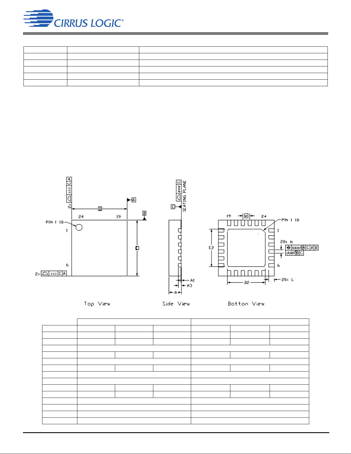
24-PIN QFN (4 mm x 4 mm Body) Package Drawing
6 Package Dimensions
Table 6-1. WLCSP Package Dimension (Cont.)
Symbol Description Dimensions
aaa Package edge tolerance 0.05
bbb Wafer flatness 0.1
ccc Coplanarity 0.03
ddd Ball/bump offset (package) 0.15
eee Ball/bump offset (ball) 0.05
1.Basic spacing between centers.
7. Controlling dimensions are in millimeters.
8. Dimensioning and tolerancing per ASME Y 14.5M.
9. Dimension “b” applies to the solder sphere diameter and is measured at the midpoint between the package body
and the seating plane.
10.Recommended reflow profile is per JEDEC/IPC J-STD-020
.
DIM MIN NOM MAX MIN NOM MAX
A 0.80 0.90 1.00 0.031 0.035 0.039
A1 0.00 0.02 0.05 0.000 0.001 0.002
A3 0.20 REF 0.008 REF
b 0.20 0.25 0.30 0.008 0.010 0.012
D 4.00 BSC 0.157 BSC
D2 2.60 2.70 2.80 0.102 0.106 0.110
e 0.50 BSC 0.020 BSC
E 4.00 BSC 0.157 BSC
E2 2.60 2.70 2.80 0.102 0.106 0.110
L 0.30 0.40 0.50 0.012 0.016 0.020
aaa 0.15 0.006
bbb 0.10 0.004
ddd 0.05 0.002
eee 0.08 0.003
Table 6-2. QFN Package Dimension
MILLIMETERS INCHES
25 DS1057F1
Page 26

Contacting Cirrus Logic Support
For all product questions and inquiries, contact a Cirrus Logic Sales Representative.
To find the one nearest you, go to www.cirrus.com.
IMPORTANT NOTICE
Cirrus Logic, Inc. and its subsidiaries (“Cirrus”) believe that the information contained in this document is accurate and reliable. However, the information is subject to change
without notice and is provided “AS IS” without warranty of any kind (express or implied). Customers are advised to obtain the latest version of relevant information to verify,
before placing orders, that information being relied on is current and complete. All products are sold subject to the terms and conditions of sale supplied at the time of order
acknowledgment, including those pertaining to warranty, indemnification, and limitation of liability. No responsibility is assumed by Cirrus for the use of this information,
including use of this information as the basis for manufacture or sale of any items, or for infringement of patents or other rights of third parties. This document is the property
of Cirrus and by furnishing this information, Cirrus grants no license, express or implied under any patents, mask work rights, copyrights, trademarks, trade secrets or other
intellectual property rights. Cirrus owns the copyrights associated with the information contained herein and gives consent for copies to be made of the information only for
use within your organization with respect to Cirrus integrated circuits or other products of Cirrus. This consent does not extend to other copying such as copying for general
distribution, advertising or promotional purposes, or for creating any work for resale.
CERTAIN APPLICATIONS USING SEMICONDUCTOR PRODUCTS MAY INVOLVE POTENTIAL RISKS OF DEATH, PERSONAL INJURY, OR SEVERE PROPERTY OR
ENVIRONMENTAL DAMAGE (“CRITICAL APPLICATIONS”). CIRRUS PRODUCTS ARE NOT DESIGNED, AUTHORIZED OR WARRANTED FOR USE IN PRODUCTS
SURGICALLY IMPLANTED INTO THE BODY, AUTOMOTIVE SAFETY OR SECURITY DEVICES, LIFE SUPPORT PRODUCTS OR OTHER CRITICAL APPLICATIONS.
INCLUSION OF CIRRUS PRODUCTS IN SUCH APPLICATIONS IS UNDERSTOOD TO BE FULLY AT THE CUSTOMER’S RISK AND CIRRUS DISCLAIMS AND MAKES
NO WARRANTY, EXPRESS, STATUTORY OR IMPLIED, INCLUDING THE IMPLIED WARRANTIES OF MERCHANTABILITY AND FITNESS FOR PARTICULAR
PURPOSE, WITH REGARD TO ANY CIRRUS PRODUCT THAT IS USED IN SUCH A MANNER. IF THE CUSTOMER OR CUSTOMER’S CUSTOMER USES OR PERMITS
THE USE OF CIRRUS PRODUCTS IN CRITICAL APPLICATIONS, CUSTOMER AGREES, BY SUCH USE, TO FULLY INDEMNIFY CIRRUS, ITS OFFICERS, DIRECTORS,
EMPLOYEES, DISTRIBUTORS AND OTHER AGENTS FROM ANY AND ALL LIABILITY, INCLUDING ATTORNEYS’ FEES AND COSTS, THAT MAY RESULT FROM OR
ARISE IN CONNECTION WITH THESE USES.
Cirrus Logic, Cirrus, the Cirrus Logic logo designs, Framework, SoundClear, SoundClear Voice, InstantAdapt, ASR Enhance, RAPID2, and DSP Composer are trademarks
of Cirrus Logic, Inc. and its subsidiaries. All other brand and product names in this document may be trademarks or service marks of their respective owners.
Microsoft Windows is a registered trademark of Microsoft Corporation.
SPI is a trademark of Motorola.
Dolby is a registered trademarks of Dolby Laboratories, Inc. Supply of an implementation of Dolby Technology does not convey a license nor imply a right under any patent,
or any other industrial or Intellectual Property Right of Dolby Laboratories, to use the Implementation in any finished end-user or ready-to-use final product. It is hereby notified
that a license for such use is required from Dolby Laboratories.
DTS is a registered trademark of the Digital Theater Systems, Inc. It is hereby notified that a third-party license from DTS is necessary to distribute software of DTS in any
finished end-user or ready-to-use final product.
Sensory and TrulyHandsfree are trademarks of Sensory, Inc. It is hereby notified that a third-party license from Sensory, Inc. is required to use or distribute its technology in
any finished end-user or ready-to-use final product.
7 Ordering Information
1. Controlling dimensions are in millimeters.
2. Dimensioning and tolerancing per ASME Y 14.5M.
3. This drawing conforms to JEDEC outline MS-012, variation VGGD-6 with exception of features D2, E2, and L,
which are per supplier designation.
4. Recommended reflow profile is per JEDEC/IPC J-STD-020.
7 Ordering Information
Check with your local Cirrus Logic representative for the availability of Automotive grade packages.
Product Description Package Pb-Free Grade Temp Range Container Order #
CS48LV12 Ultralow Power DSP 20 BALL
WLCSP
24 PIN QFN YES Commercial 0 °C to +70°C Tape and Reel CS48LV12-CNZR
24 PIN QFN YES Automotive –40°C to +105°C Tape and Reel CS48LV12-ENZR
CS48LV13 Ultralow Power DSP 20 BALL
WLCSP
24 PIN QFN YES Commercial 0 °C to +70°C Tape and Reel CS48LV13-CNZR
24 PIN QFN YES Automotive –40°C to +105°C Tape and Reel CS48LV13-ENZR
Reference: Philips Semiconductor, The I²C-Bus Specification: Version 2.1, January 2000.
YES Commercial 0 °C to +70°C Tape and Reel CS48LV12-CWZR
YES Commercial 0 °C to +70°C Tape and Reel CS48LV13-CWZR
8 Revision History
Revision Date Changes
F1 February, 2014 Initial release.
DS1057F1 26
 Loading...