

Page 1

User Manual
Page 2

TABLE OF CONTENTS
TABLE OF CONTENTS
1. Before You Begin ....................................................................... 1
What Is Included ........................................................................................... 1
Unpacking Instructions.................................................................................. 1
Claims ................................................................................................................ 1
Text Conventions .......................................................................................... 1
Symbols ........................................................................................................ 1
Disclaimer ..................................................................................................... 1
Product at a Glance ...................................................................................... 2
Safety Notes.................................................................................................. 2
2. Introduction ................................................................................ 3
Product Overview.......................................................................................... 3
Product Dimensions ...................................................................................... 4
3. Setup ........................................................................................... 5
AC Power...................................................................................................... 5
Fuse Replacement ............................................................................................. 5
Power Linking..................................................................................................... 5
Mounting ....................................................................................................... 6
Orientation.......................................................................................................... 6
Rigging ............................................................................................................... 6
Multi-Bracket Mounting ...................................................................................... 7
4. Operation .................................................................................... 8
Control Panel Operation................................................................................ 8
Menu Map ..................................................................................................... 8
Configuration (DMX) ..................................................................................... 10
Starting Address................................................................................................. 10
Static Mode ........................................................................................................ 10
Auto Programs ................................................................................................... 10
Sound-Active Mode............................................................................................ 11
Sensitivity Mode ................................................................................................. 11
Master/Slave ...................................................................................................... 11
Dimmer Profiles.................................................................................................. 11
LED Frequency .................................................................................................. 12
Fan Mode ........................................................................................................... 12
Back Light .......................................................................................................... 12
DMX Fail ............................................................................................................ 12
System Information ............................................................................................ 12
Factory Reset..................................................................................................... 12
DMX Channel Assignments and Values ....................................................... 13
8Ch..................................................................................................................... 13
7Ch..................................................................................................................... 13
4Ch..................................................................................................................... 14
2Ch..................................................................................................................... 14
1Ch..................................................................................................................... 14
5. Maintenance................................................................................ 15
Product Maintenance .................................................................................... 15
6. Technical Specifications ........................................................... 16
Returns........................................................................................ 17
Contact Us .................................................................................. 18
Shocker 2 User Manual Rev. 2
Page 3
BEFORE YOU BEGIN
1. BEFORE YOU BEGIN
What Is Included
•Shocker 2
• Power Cord
• Hanging Bracket
• Expansion bracket
Unpacking Instructions
Carefully unpack the product immediately and check the container to make sure all the parts are in the
package and are in good condition.
Claims
If the box or the contents (the product and included accessories) appear damaged from shipping, or show
signs of mishandling, notify the carrier immediately, not Chauvet. Failure to report damage to the carrier
immediately may invalidate your claim. In addition, keep the box and contents for inspection.
For other issues, such as missing components or parts, damage not related to shipping, or concealed
damage, file a claim with Chauvet within 7 days of delivery.
Text Conventions
CONVENTION MEANING
1–512 A range of values
50/60 A set of values of which only one can be chosen
Settings A menu option not to be modified
<ENTER> A key to be pressed on the product’s control panel
ON A value to be entered or selected
• Warranty Card
• Quick Reference Guide
• User Manual
Symbols
SYMBOL MEANING
Electrical warning. Not following these instructions may cause electrical damage to
the product, accessories, or the user.
Critical installation, configuration, or operation information. Not following these
instructions may make the product not work, cause damage to the product, or cause
harm to the operator.
Important installation or configuration information. The product may not function
correctly if this information is not used.
Useful information.
Disclaimer
Chauvet believes that the information contained in this manual is accurate in all respects. However,
Chauvet assumes no responsibility and specifically disclaims any and all liability to any party for any loss,
damage or disruption caused by any errors or omissions in this document, whether such errors or
omissions result from negligence, accident or any other cause. Chauvet reserves the right to revise the
content of this document without any obligation to notify any person or company of such revision, however,
Chauvet has no obligation to make, and does not commit to make, any such revisions. Download the latest
version from www.chauvetdj.com
The works of authorship contained in this manual, including, but not limited to, all design, text and images
are owned by Chauvet.
© Copyright 2018 Chauvet & Sons, LLC. All rights reserved.
Electronically published by Chauvet in the United States of America.
CHAUVET, the Chauvet logo, and Shocker 2 are registered trademarks or trademarks of Chauvet & Sons
LLC (d/b/a Chauvet and Chauvet Lighting) in the United States and other countries. Other company and
product names and logos referred to herein may be trademarks of their respective companies.
.
Shocker 2 User Manual Rev. 2
Page 1 of 18
Page 4
Product at a Glance
BEFORE YOU BEGIN
Use on Dimmer
Outdoor Use
Sound-Active
DMX
Master/Slave
Safety Notes
• Always connect the product to a grounded circuit to avoid the risk of electrocution.
• Always disconnect the product from the power source before cleaning or replacing the
fuse.
• Avoid direct eye exposure to the light source while the product is on.
• Make sure the power cord is not crimped or damaged.
• Never disconnect the product from power cord by pulling or tugging on the cord.
• If mounting the product overhead, always secure to a fastening device using a safety cable.
• Make sure there are no flammable materials close to the product when operating.
• Do not touch the product’s housing when operating because it may be very hot.
• The product is not intended for permanent installation.
• Do not expose the product to rain or moisture.
• Always make sure that the voltage of the outlet to which you are connecting the product is
within the range stated on the decal or rear panel of the product.
• The product is for indoor use only! (IP20) To prevent risk of fire or shock, do not expose the
product to rain or moisture.
• Always install the product in a location with adequate ventilation, at least 20 in (50 cm) from
adjacent surfaces.
• Be sure that no ventilation slots on the product’s housing are blocked.
• Never connect the product to a dimmer.
• Make sure to replace the fuse with another of the same type and rating.
• Never carry the product from the power cord or any moving part. Always use the hanging/
mounting bracket.
• The maximum ambient temperature (Ta) is 104 °F (40 °C). Do not operate the product at
higher temperatures.
• In the event of a serious operating problem, stop using the product immediately.
• Never try to repair the product. Repairs carried out by unskilled people can lead to damage
or malfunction. Please contact the nearest authorized technical assistance center.
• To eliminate unnecessary wear and improve its lifespan, during periods of non-use
completely disconnect the product from power via breaker or by unplugging it.
Auto Programs
Auto-ranging Power Supply
Replaceable Fuse
User-Serviceable
Page 2 of 18
Keep this User Manual for future use. If you sell the product to someone else, be sure that
they also receive this document.
Shocker 2 User Manual Rev. 2
Page 5
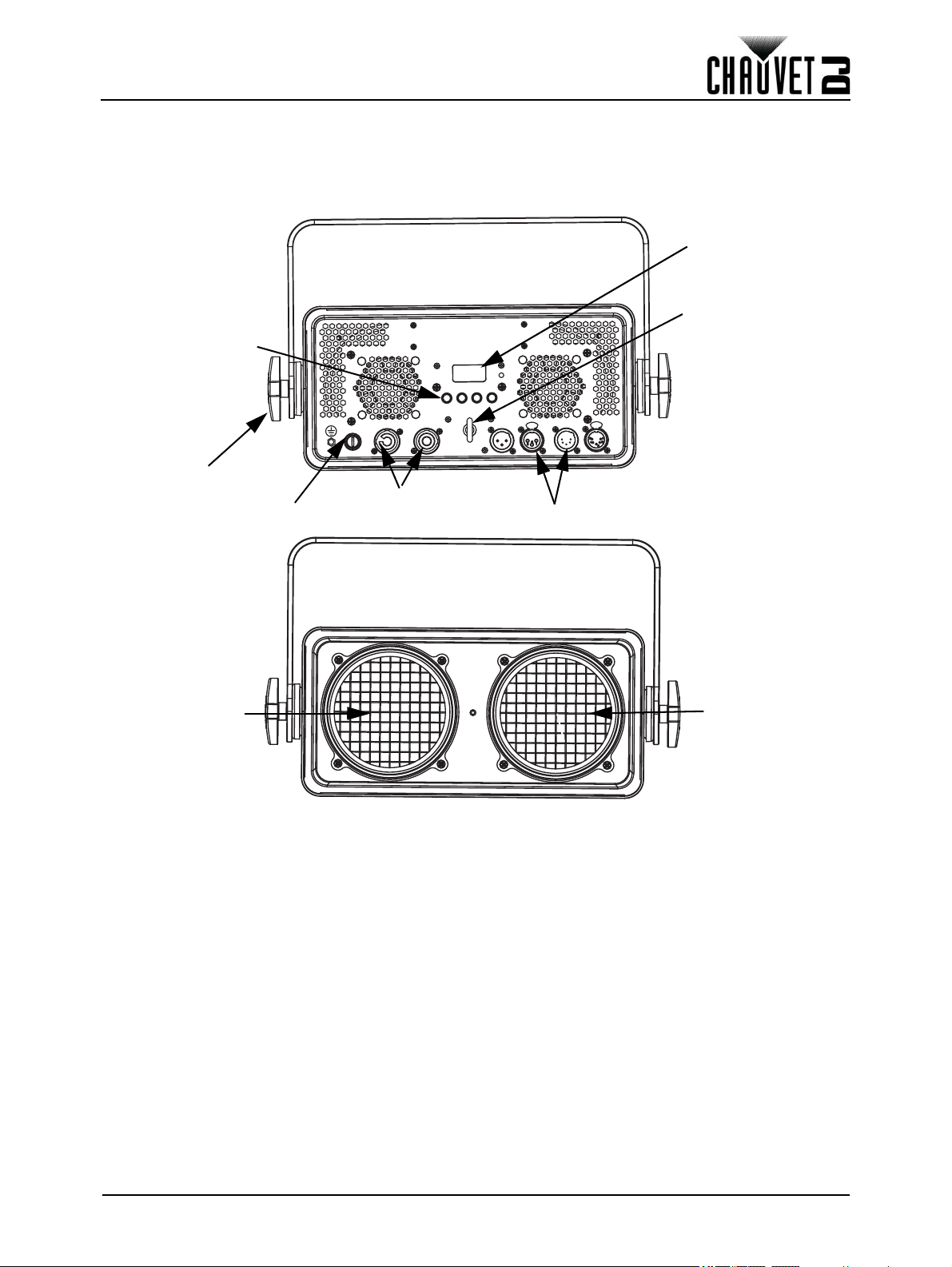
INTRODUCTION
DMX In/Out
Fuse Holder
Power
In/Out
Menu Buttons
LED Display
Bracket
Adjustment
Knob
Safety
Loop
Zone 2
Zone 1
2. INTRODUCTION
Product Overview
Shocker 2 User Manual Rev. 2
Page 3 of 18
Page 6
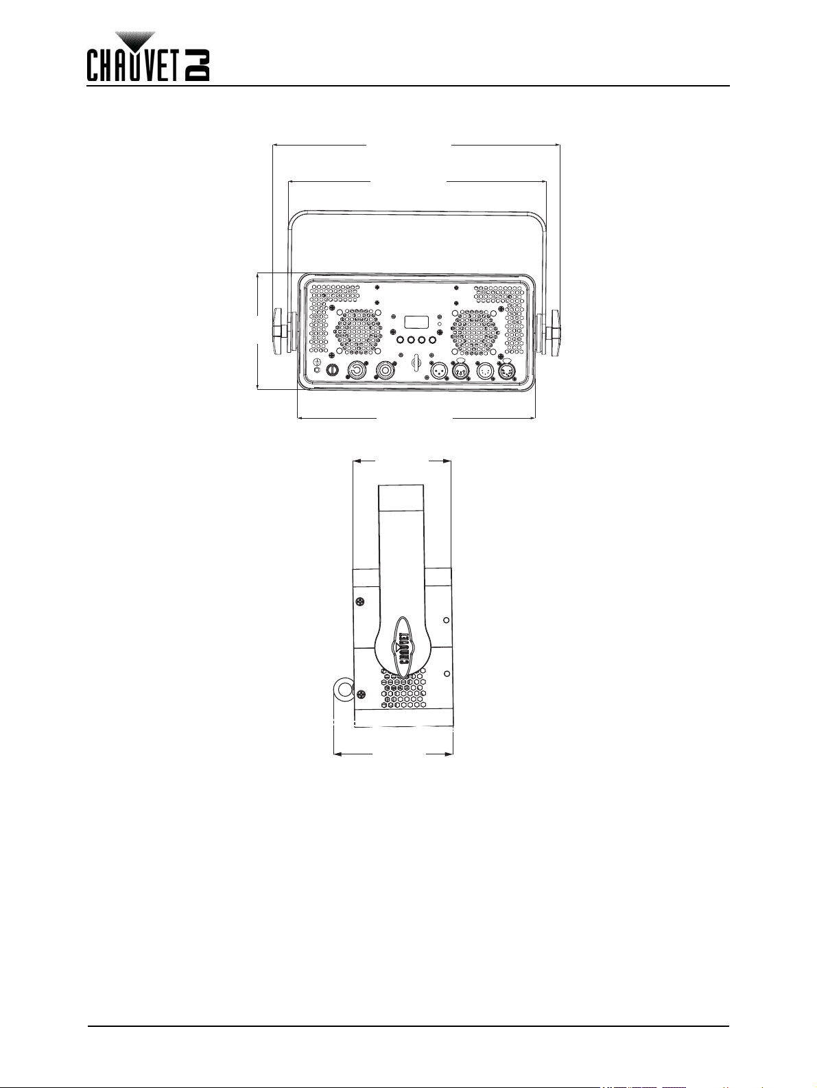
Product Dimensions
14.75 in
374.5 mm
6 in
153 mm
10.3 in
116 mm
3.8 in
96 mm
13.24 in
336.5 mm
12.2 in
309.5 mm
INTRODUCTION
Page 4 of 18
Shocker 2 User Manual Rev. 2
Page 7

SETUP
2nd Product
3
rd
Product
Additional
Products
Power
Source
1
st
Product
3. SETUP
AC Power
The Shocker 2 has an auto-ranging power supply and it can work with an input voltage range of 100 to 240
VAC, 50/60 Hz. To determine the product’s power requirements (circuit breaker, power outlet, and wiring),
use the current value listed on the label affixed to the product’s back panel, or refer to the product’s
specifications chart. The listed current rating indicates the product’s average current draw under normal
conditions.
• Always connect the product to a protected circuit (a circuit breaker or fuse).
Make sure the product has an appropriate electrical ground to avoid the risk of
electrocution or fire.
• To eliminate unnecessary wear and improve its lifespan, during periods of nonuse completely disconnect the product from power via breaker or by
unplugging it.
Never connect the product to a rheostat (variable resistor) or dimmer circuit, even if
the rheostat or dimmer channel serves only as a 0 to 100% switch.
Fuse Replacement
1. Disconnect this product from the power outlet.
2. Using a Phillips-head screwdriver, unscrew the fuse holder cap from the housing.
3. Remove the blown fuse and replace with another fuse of the same type and rating (T 2 A, 250 V).
4. Screw the fuse holder cap back in place and reconnect power.
Disconnect the product from the power outlet before replacing the fuse.
Power Linking
The product provides power linking via the powerCON® outlet located in the back of the product. Please
see the diagram below for further explanation.
Power Linking Diagram
You can power link up to 6 Shocker 2 products on 120 VAC or up to 12 Shocker 2
products on 230 VAC.
The power linking diagram corresponds to the North American version of the
product ONLY! If using the product in other markets, you must consult with the local
Chauvet distributor as power linking connectors and requirements may differ in
your country or region.
Shocker 2 User Manual Rev. 2
Page 5 of 18
Page 8

SETUP
Mounting Bracket
Safety Cable
(such as CH-05 from
Chauvet)
Mounting Clamp
(such as CLP-15 or CLP-15N
from Chauvet)
Bracket
Adjustment Knob
Mounting
Before mounting the product, read and follow the safety recommendations indicated in the Safety Notes.
Orientation
The Shocker 2 may be mounted in any position; however, make sure adequate ventilation is provided
around the product.
Rigging
• Before deciding on a location, always make sure there is easy access to the product for
maintenance and programming purposes.
• Make sure adequate ventilation is provided around the product.
• Make sure that the structure or surface onto which you are mounting the product can support the
product’s weight. (see the Technical Specifications
• When mounting the product overhead, always use a safety cable. Mount the product securely to a
rigging point, whether an elevated platform or a truss.
• When rigging the product onto a truss, use a mounting clamp of appropriate weight capacity.
• When power linking multiple products, mount the products close enough for power linking cables to
reach.
• The bracket adjustment knobs allow for directional adjustment when aiming the product to the
desired angle. Only loosen or tighten the bracket knobs manually. Using tools could damage the
knobs.
Mounting Diagram
)
Page 6 of 18
Shocker 2 User Manual Rev. 2
Page 9

SETUP
Safety Cable
(such as CH-05 from
Chauvet)
Bracket
Adjustment Knob
Expansion Bracket
Mounting Bracket
Multi-Bracket Mounting
The Shocker 2 Expansion Brackets allow the creation of multi-fixture banks with ease. Link up to 2
products vertically from any mounting point. Make sure the mounting clamps are capable of supporting the
combined weight of the products. For our CHAUVET line of mounting clamps, go to http://trusst.com/
products.
Shocker 2 User Manual Rev. 2
Page 7 of 18
Page 10

OPERATION
4. OPERATION
Control Panel Operation
To access the control panel functions, use the four buttons located underneath the display. Please refer to
the Product Overview
BUTTON FUNCTION
<MENU> Press to find an operation mode or to back out of the current menu option
<UP> Press to scroll up the list of options or to find a higher value
<DOWN> Press to scroll down the list of options or to find a lower value
<ENTER> Press to activate a menu option or a selected value
Menu Map
MODE PROGRAMMING LEVELS DESCRIPTION
DMX Address 001-505 Selects DMX address
DMX Channel
Static
to see the button locations on the control panel.
1Ch
2Ch
4Ch
7Ch
8Ch
Dimmer 000
Strobe 000
255 Sets the intensity of the light output
255 Selects the strobe frequency
Sets 1-channel DMX mode and
DMX starting address
Sets 2-channel DMX mode and
DMX starting address
Sets 4-channel DMX mode and
DMX starting address
Sets 7-channel DMX mode and
DMX starting address
Sets 8-channel DMX mode and
DMX starting address
Page 8 of 18
Shocker 2 User Manual Rev. 2
Page 11

OPERATION
MODE PROGRAMMING LEVELS DESCRIPTION
Auto 1
Auto 2
Auto 3
Auto 4
Auto 5
Auto 6
Auto 7
Automatic
Show
Auto 8
Auto 9
Auto 10
Auto 11
Auto 12
Auto 13
Auto 14
Dimmer 000
Speed 000
Dimmer 000
Speed 000
Dimmer 000
Speed 000
Dimmer 000
Speed 000
Dimmer 000
Speed 000
Dimmer 000
Speed 000
Dimmer 000
Speed 000
Dimmer 000
Speed 000
Dimmer 000
Speed 000
Dimmer 000
Speed 000
Dimmer 000
Speed 000
Dimmer 000
Speed 000
Dimmer 000
Speed 000
Dimmer 000
Speed 000
Sound 1
Sound 2
Sound Show
Sound 3
Sound 4
Sound 5
Sensitivity 000-100 Sound sensitivity, low to high
Master/Slave
Master
Slave
Slave 1
Slave Mode
Slave 2
Slave 3
Slave 4
Off Dimmer off
Dimmer Mode
Dimmer 1
Dimmer 3
255
255
255
255
255
255
255
255
255
255
255
255
255
255
255
255
255
255
255
255
255
255
255
255
255
255
255
255
Sets Auto mode programs 1–14
Sound-active programs 1-5
Sets Master/Slave mode
Selects slave modes 1-4
Selects dimmer modes 1-3Dimmer 2
Shocker 2 User Manual Rev. 2
Page 9 of 18
Page 12

MODE PROGRAMMING LEVELS DESCRIPTION
600Hz
1200Hz
LED Frequency
Fan Mode
Back Light
DMX Fail
2000Hz
4000Hz
6000Hz
25KHz
Auto
On
On Display backlight always on
10S
20S
30S
Hold
Blackout
Selects the PWM output frequency
Fan control
Turns off display backlight after 10
sec of inactivity
Turns off display backlight after 20
sec of inactivity
Turns off display backlight after 30
sec of inactivity
Continues last command upon loss
of DMX signal
Blacks out product upon loss of
DMX signal
OPERATION
Configuration (DMX)
The Shocker 2 works with a DMX controller. Information about DMX is in the CHAUVET DMX Primer,
which is available from the Chauvet website http://www.chauvetlighting.com.
Starting Address
When selecting a starting DMX address, always consider the number of DMX channels the selected DMX
mode uses. If you choose a starting address that is too high, you could restrict the access to some of the
product’s channels.
The Shocker 2 uses up to 8 DMX channels, which defines the highest configurable address as 505.
If you are not familiar with the DMX protocol, download the DMX Primer from www.chauvetdj.com
To select the starting address, do the following:
1. Press <MENU> repeatedly until 1-Ch, 2-Ch, 4-Ch, 7-Ch, or 8-Ch shows on the display.
2. Press <ENTER>.
3. Use <UP> or <DOWN> to select the starting address, from 001-506.
4. Press <ENTER>.
Static Mode
The Static mode allows for permanent dimmer and strobe presets without a DMX controller.
1. Go to the Static main level.
2. Select Dimmer or Strobe.
3. Select the desired value (000–255).
Auto Programs
Auto programs allow for dynamic blinder effects without a DMX controller.
1. Go to the Auto Show main level
2. Select the desired auto (Auto 1–14).
3. Press Enter.
4. Select Dimmer or Strobe.
5. Select the desired value (000-255).
.
Page 10 of 18
Shocker 2 User Manual Rev. 2
Page 13

OPERATION
Sound-Active Mode
To run the Shocker 2 in sound-active mode, do the following:
1. Press <MENU> repeatedly until Sound Show on the display.
2. Press <ENTER>.
3. Use <UP> or <DOWN> to select a sound-active program, from Sound 1–5.
4. Press <ENTER>.
Sensitivity Mode
To change the sound sensitivity level, follow the instructions below.
1. Press <MENU> repeatedly until Sensitivity on the display.
2. Press <ENTER>.
3. Use <UP> or <DOWN> to select a sound-active program, from (000-100).
4. Press <ENTER
Master/Slave
The Master/Slave mode allows a group of Shocker 2 products (the slaves) to simultaneously duplicate the
output of another Shocker 2 (the master) without a DMX controller.
To set each of the slaves:
1. Go to the Master/Slave main level
2. Select Slave (1-4)
To set the master:
1. Go to the Master/Slave main level
2. Select Master.
3. Select an auto program as explained in Auto Programs, or a static setting.
• The master is the one that runs a program whether in Auto or Static mode.
• Do not connect a DMX controller to the products configured for Master/Slave
operation. The DMX controller may interfere with signals from the master.
• The master should be the first product in the daisy chain.
Dimmer Profiles
This setting determines how fast the output of the Shocker 2 changes when you modify the output value.
This setting provides four different options to simulate the dimming curve of an incandescent lighting
product.
• Go to the Dimmer Mode main level.
• Select a dimmer curve (OFF, Dimmer 1, Dimmer 2, or Dimmer 3).
Shocker 2 User Manual Rev. 2
Page 11 of 18
Page 14

OPERATION
LED Frequency
This option changes the Pulse Width Modulation (PWM) frequency of the LEDs on the Shocker 2.
1. Go to the LED Frequency main level.
2. Select PWM Frequency (600Hz, 1200Hz, 2000Hz, 4000Hz, 6000Hz or 25Khz).
Fan Mode
This setting determines how the fan speed on the Shocker 2 is set.
1. Go to the Fan Mode main level
2. Select Auto (fan speed will increase or decrease based on product temperature) or On (fan
speed will always be at maximum).
Back Light
This setting allows for selection of the amount of time the backlight on the Shocker 2’s display stays on
after the last button is pressed on the control panel.
1. Go to the Back Light main level.
2. Select On (remains on), 10S (10 seconds), 20S (20 seconds), or 30S (seconds).
DMX Fail
These options determine what happens when DMX signal is lost or interrupted
1. Go to the main level.
2. Select the DMX FAIL programming level.
3. Select either HOLD (holds the last received DMX input) or BLACKOUT (blacks out the product).
System Information
This option displays the total number of hours the product has run, the installed software version, and the
product’s UID.
1. Go to the Information main level.
2. Select Fixture Hours or Version.
Factory Reset
This option restores the Shocker 2 to factory default settings.
1. Go to the Reset Factory main level.
2. Select No or Yes .
Page 12 of 18
Shocker 2 User Manual Rev. 2
Page 15

OPERATION
DMX Channel Assignments and Values
8Ch
CHANNEL FUNCTION VALUE PERCENT/SETTING
1 Dimmer 000 255 0–100%
2 White 1 000
3 White 2 000
4Strobe
5 Auto Programs
Auto Speed 000
6
Sound Sensitivity
7 Master/Slave Mode
8 Dimmer Speed Mode
255 0–100%
255 0–100%
010 No function
000
011
132 Strobe, slow to fast
133
255 Random strobe macros
000
010 No function
011
027 Auto program 1
028
044 Auto program 2
045
061 Auto program 3
062
078 Auto program 4
079
095 Auto program 5
096
112 Auto program 6
113
129 Auto program 7
130
146 Auto program 8
147
163 Auto program 9
164
180 Auto program 10
181
197 Auto program 11
198
214 Auto program 12
215
231 Auto program 13
232
249 Auto program 14
250
255 Sound show (program 4)
255 Speed, slow to fast
000
010 Sound sensitivity off
011
255 Sound sensitivity, low to high
000
006 No function
007
050 Master
051
100 Slave 1
101
150 Slave 2
151
200 Slave 3
201
255 Slave 4
000
051 Preset dimmer speed
052
101 Dimmer speed mode off
102
152 Dimmer speed mode 1, fastest speed
153
203 Dimmer speed mode 2, middle speed
204
255 Dimmer speed mode 3, slow speed
7Ch
CHANNEL FUNCTION VALUE PERCENT/SETTING
1 Dimmer 000 255 0–100%
2 White 1 000
3 White 2 000
4Strobe
Shocker 2 User Manual Rev. 2
255 0–100%
255 0–100%
000
010 No function
011
255 Strobe, slow to fast
Page 13 of 18
Page 16

CHANNEL FUNCTION VALUE PERCENT/SETTING
000
010 No function
011
040 Auto program 1
041
080 Auto program 2
081
5 Auto Programs
Auto Speed 000
6
Sound Sensitivity
7 Dimmer Speed Mode
120 Auto program 3
121
170 Auto program 4
171
220 Auto program 5
221
249 Auto program 6
250
255 Sound show (program 4)
255 Speed, slow to fast
000
010 Sound sensitivity off
011
255 Sound sensitivity, low to high
000
051 Preset dimmer speed
052
101 Dimmer speed mode off
102
152 Dimmer speed mode 1, fastest speed
153
203 Dimmer speed mode 2, middle speed
204
255 Dimmer speed mode 3, slow speed
4Ch
CHANNEL FUNCTION VALUE PERCENT/SETTING
1 Dimmer 000
2 White 1 000
3 White 2 000
4 Strobe
255 0–100%
255 0–100%
255 0–100%
000
010 No function
011
255 Strobe, slow to fast
OPERATION
2Ch
CHANNEL FUNCTION VALUE PERCENT/SETTING
1 White 1 000
2 White 2 000
255 0–100%
255 0–100%
1Ch
CHANNEL FUNCTION VALUE PERCENT/SETTING
1 Dimmer 000
255 0–100%
Page 14 of 18
Shocker 2 User Manual Rev. 2
Page 17

MAINTENANCE
5. MAINTENANCE
Product Maintenance
Dust build-up reduces light output performance and can cause overheating. This can lead to reduction of
the light source’s life and/or mechanical wear. To maintain optimum performance and minimize wear, clean
your lighting products at least twice a month. However, be aware that usage and environmental conditions
could be contributing factors to increase the cleaning frequency.
To clean the product, follow the instructions below:
1. Unplug the product from power.
2. Wait until the product is at room temperature.
3. Use a vacuum (or dry compressed air) and a soft brush to remove dust collected on the external
surface/vents.
4. Clean all transparent surfaces with a mild soap solution, ammonia-free glass cleaner, or isopropyl
alcohol.
5. Apply the solution directly to a soft, lint free cotton cloth or a lens cleaning tissue.
6. Softly drag any dirt or grime to the outside of the transparent surface.
7. Gently polish the transparent surfaces until they are free of haze and lint.
Always dry the transparent surfaces carefully after cleaning them.
Do not spin the cooling fan using compressed air because it may damage it.
Shocker 2 User Manual Rev. 2
Page 15 of 18
Page 18

TECHNICAL SPECIFICATIONS
6. TECHNICAL SPECIFICATIONS
Dimensions and Weight
LENGTH WIDTH HEIGHT WEIGHT
14.75in (375 mm) 4.6 in (116 mm) 6 in (153 mm) 10.4 lb (4.7 kg)
Note: Dimensions in inches rounded to the nearest decimal digit.
Power
POWER SUPPLY TYPE RANGE VOLTAGE SELECTION
Switching (internal) 100 to 240 VAC, 50/60 Hz Auto-ranging
PARAMETER 120 V, 60 HZ 230 V, 50 HZ
Consumption 154W 148 W
Operating Current 1.26 A 0.65 A
Power linking current (products) 8 A (6 products) 8A (12 products)
Fuse T 2A, 250 V T 2A, 250 V
POWER I/O U.S./WORLDWIDE UK/EUROPE
Power input connector powerCON®-compatible powerCON®-compatible
Power output connector powerCON®-compatible powerCON®-compatible
Power Cord plug Edison (U.S.) Local Plug
Light Source
TYPE COLOR QUANTITY POWER CURRENT LIFESPAN
LED COB LEDs 2 85 W 3.6 A 50,000 hours
Photometrics
STROBE RATE BEAM ANGLE FIELD ANGLE ILLUMINANCE @ 2 M ILLUMINANCE @ 5 M
0 to 400 Hz 51° 81° 1,080 lux per pod 161 lux per pod
Thermal
MAXIMUM EXTERNAL TEMPERATURE COOLING SYSTEM
104 °F (40 °C) Fan-assisted convection
DMX
I/O CONNECTOR CHANNEL RANGE
3-pin XLR 1, 2, 4, 7, or 8
Ordering
PRODUCT NAME ITEM NAME ITEM CODE UPC NUMBER
Shocker 2 SHOCKER2 0301453 781462218010
Page 16 of 18
Shocker 2 User Manual Rev. 2
Page 19

RETURNS
RETURNS
In case you need to get support or return a product:
• If you are located in the U.S., contact Chauvet World Headquarters.
• If you are located in the UK or Ireland, contact Chauvet Europe Ltd.
• If you are located in Benelux, contact Chauvet Europe BVBA.
• If you are located in France, contact Chauvet France.
• If you are located in Germany, contact Chauvet Germany.
• If you are located in Mexico, contact Chauvet Mexico.
• If you are located in any other country, DO NOT contact Chauvet. Instead, contact your local
distributor. See www.chauvetdj.com
Germany, or Mexico.
If you are located outside the U.S., UK, Ireland, Benelux, France, Germany, or Mexico,
contact your distributor of record and follow their instructions on how to return Chauvet
products to them. Visit our website www.chauvetdj.com
Call the corresponding Chauvet Technical Support office and request a Return Merchandise Authorization
(RMA) number before shipping the product. Be prepared to provide the model number, serial number, and
a brief description of the cause for the return.
To submit a service request online, go to www.chauvetdj.com/service-request
Send the merchandise prepaid, in its original box, and with its original packing and accessories. Chauvet
will not issue call tags.
Clearly label the package with the RMA number. Chauvet will refuse any product returned without an RMA
number.
for distributors outside the U.S., UK, Ireland, Benelux, France,
for contact details.
.
Write the RMA number on a properly affixed label. DO NOT write the RMA number
directly on the box.
Before sending the product, clearly write the following information on a piece of paper and place it inside
the box:
• Your name
• Your address
• Your phone number
•RMA number
• A brief description of the problem
Be sure to pack the product properly. Any shipping damage resulting from inadequate packaging will be
your responsibility. FedEx packing or double-boxing are recommended.
Chauvet reserves the right to use its own discretion to repair or replace returned
product(s).
Shocker 2 User Manual Rev. 2
Page 17 of 18
Page 20

CONTACT US
General Information Technical Support
World Headquarters
UK
Benelux
France
Germany
Mexico
Address: Av. de las Partidas 34 - 3B
Lerma, Edo. de México, CP 52000
CONTACT US
Address: 5200 NW 108th Ave. Voice: (844) 393-7575
Sunrise, FL 33351 Fax: (954) 756-8015
Voice: (954) 577-4455 Email: chauvetcs@chauvetlighting.com
Fax: (954) 929-5560
Toll Free: (800) 762-1084 Website: www.chauvetdj.com
Address: Unit 1C Email: UKtech@chauvetlighting.eu
Brookhill Road Industrial Estate
Pinxton, Nottingham, UK Website: www.chauvetdj.eu
NG16 6NT
Voice: + 44 (0) 17 73 511115
Fax : +44 (0) 1773 511110
Address: Stokstraat 18 Email: BNLtech@chauvetlighting.eu
9770 Kruishoutem
Belgium Website: www.chauvetdj.eu
Voice: +32 9 388 93 97
Address: 3, Rue Ampère
91380 Chilly-Mazarin
France Website: www.chauvetdj.eu
Voice: +33 1 78 85 33 59
Address: Bruno-Bürgel-Str. 11
28759 Bremen
Germany Website: www.chauvetdj.eu
Voice: +49 421 62 60 20
(Entrance by Calle 2)
Zona Industrial Lerma Website: www.chauvetdj.mx
Voice: +52 (728) 690-2010
Email: FRtech@chauvetlighting.fr
Email: DEtech@chauvetlighting.de
Email: servicio@chauvet.com.mx
Outside the U.S., U.K., Ireland, France, Germany, Benelux, or Mexico, contact the dealer of record. Follow the instructions to request support or to return a product. Visit our website for contact details.
Page 18 of 18
Shocker 2 User Manual Rev. 2
 Loading...