

Page 1

User Manual
Page 2

TABLE OF CONTENTS
1. Before You Begin................................................................................3
What Is Included ........................................................................................... 3
Unpacking Instruc tions .................................................................................. 3
Claims ................................................................................................................... 3
Text Conventions .......................................................................................... 3
Icons ............................................................................................................. 3
Document Information ................................................................................... 3
Product at a Glance ....................................................................................... 4
Safety Notes ................................................................................................. 4
2. Introduction.........................................................................................5
Product Overview .......................................................................................... 5
Product Dimensions ...................................................................................... 6
3. Setup ...................................................................................................7
AC Power ...................................................................................................... 7
Fus e Repl acement ................................................................................................. 7
Power Linking ........................................................................................................ 8
Mounting ....................................................................................................... 9
Orientation ............................................................................................................. 9
Rigging .................................................................................................................. 9
4. Operation ..........................................................................................10
Control Panel Operation .............................................................................. 10
Menu Map ................................................................................................... 10
Configuration ( DM X) .................................................................................... 11
DMX Personalities and Starting Address .............................................................. 11
DMX Channel Assignments and Values....................................................... 11
3-CH .................................................................................................................... 11
Configuration ( S tandalone) .......................................................................... 12
Sound-Active Mode .............................................................................................. 12
Automatic Mode ................................................................................................... 12
Master/Slave Mode .............................................................................................. 12
5. Technical Information ......................................................................13
Product Maintenanc e .................................................................................. 13
General Troubleshooting ............................................................................. 14
Contact Procedur e ...................................................................................... 15
CHAUVET® Contact Inf ormation ................................................................. 15
Returning Produc ts to CHAUVET® .............................................................. 15
6. Techni cal Sp eci f ications ..................................................................16
Page 2 of 16 Radius™ 2.0 User Manual Rev. 2
Page 3
What Is
Included
Unpacking
Instructions
included
upon receipt
Failure to do so in a timely manner may
cking
For other issues such as missing components or parts, damage not related to shi pping,
within seven (7) days of receiving
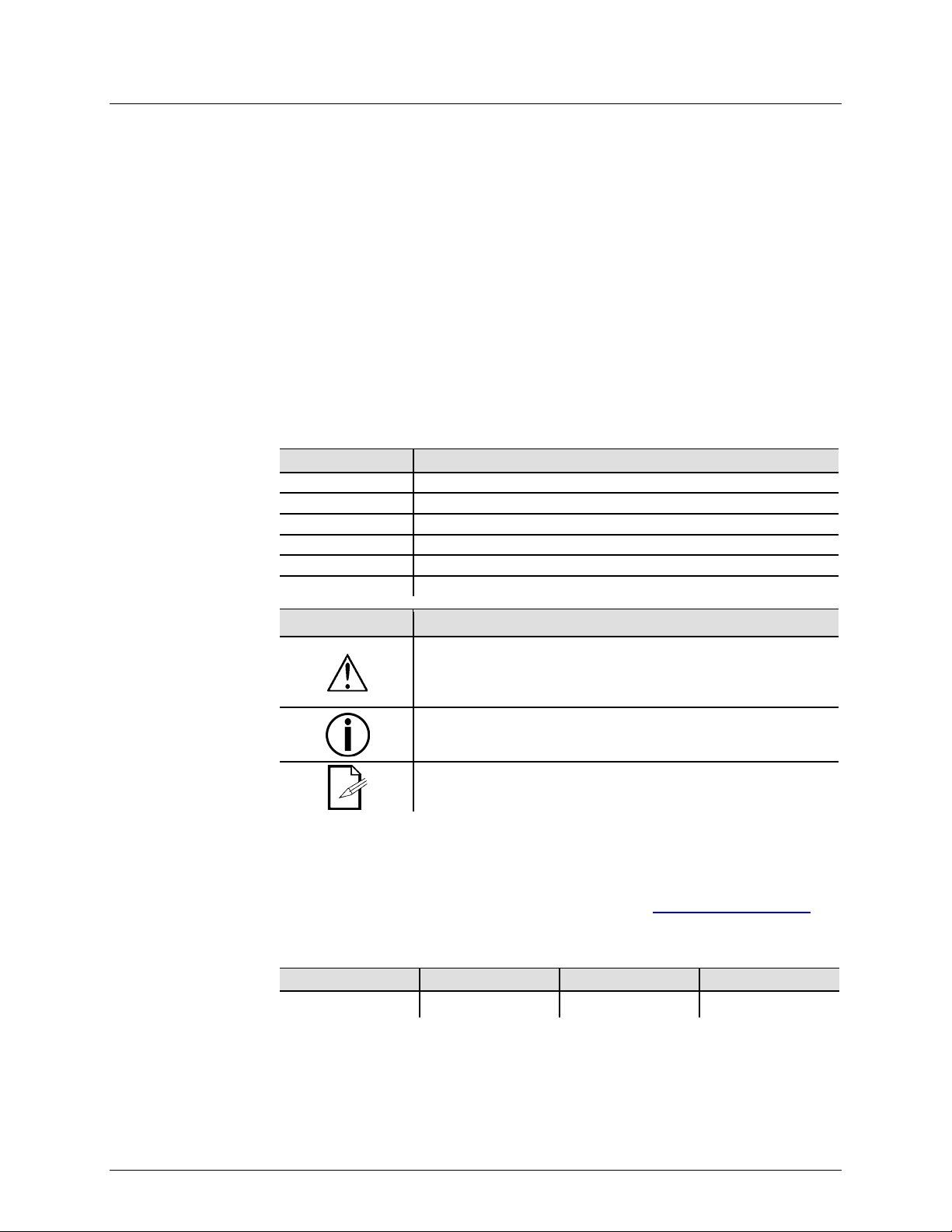
Text
1—512
A range of values
50/60
A set of values of which only one can be chosen
Settings
A menu option not to be modified
Menu > Settings
A seq uence of menu opti ons to b e followed
<ENTER>
A key t o be pr essed on th e product’s control panel
ON
A value t o be entered or selected
Icons
This paragraph contai ns critical installation, configur ation, or
damage to the product, or cause harm to the user.
This paragraph contains important installation or configu ra tion
the product from functioning correctly.
Document
The information and specifications contained in this document are subject to change
without notice. CHAUVET® assumes no responsibility or liability for any errors or
CHAUVET® reserves the right to update the
1. BEFORE YOU BEGIN
Claims
Conventions
• 1 x Radius™ 2.0
• 1 x Power Cord
Immediately upon receipt, carefully unpack the product and check the contai ner to make
sure you have received all the parts indicat ed above in good condition.
If the container or the material inside the container (the product and
accessories) appear damaged from shipp ing, or show signs of mishandling,
notify the carrier immediately, not CHAUVET®.
invalidate your claim with the carrier. In addition, keep t he container and all the pa
material for inspection.
or concealed damage, file a claim with CHAUVET®
the merchandise.
Convention Meaning
Icon Meaning
• 1 x Warran ty Card
• 1 x Quick R eference Guid e
operation information. Failure to comply with this information may
render the product parti al ly or completely i noperative, caus e
information. F ail ure to comply with this in form ati on may p revent
This paragraph reminds you of useful, alt hough not critical,
information.
Information
omissions that may appear in t his manual.
existing docum ent or t o c reate a new document to correct any errors or omis sions.
You can download the lat est version of this doc ument f rom www.chauvetlighting.com.
© Copyright 2013 CHAUVET®. All rights reserved.
Electronically published by CHAUVET® in the U nited St ates of Am er ica.
A. Leon 06/14/13 T. Yeago 06/17/13
Author Date Editor Date
Radius™ 2.0 User Manual Rev. 2 Page 3 of 16
Page 4
Product at a
x
P
x
P
P
P
P
x
P
Safety Notes
Do not touch the product’s housing when operating because it may be very hot.
• Always m ake s ure that the voltag e of the outlet to which you are connect ing the
center.
Glance
Use on Dimmer
Out door Use
Sound-Activated
DMX
Master/Slave
Please read the following Safet y Not es c arefu lly b efore working with the product. The
Notes include impor tant safety information about installation, usage, and maintenance.
• Always connect the product to a grounded circ uit to avoid the risk of electrocution.
• Always disconnect the product from the power source before cleaning or replacing
the fuse.
• Avo id di rect eye exp osure to the l ight sour ce whi le th e product is on.
• Make sure the power cord is not crimped or damaged.
• Never disconnect the product from power cord by pulling or tugging on the cord.
• If mounting the product overhead, always secure to a fastening d evice using a
safety cable.
• Make sure th ere are no flammable materials close to the product when operating.
•
product is within the range stated on the decal or rear panel of the product.
• The product is for indoor us e only! (I P20) T o prevent risk of fire or shock, do n ot
expose the product to rain or moistu re.
• Always install the product in a location with adequate ventilation, at least 20 i n
(50 cm) from adjacent surfaces.
• Be su re that no ventilation slots on the product’s housing are blocked.
• Nev er co nnect the product to a dimmer.
• Make sure to repl ace the fus e w ith a noth er of t he same typ e and r ati ng.
• Nev er ca r ry the product from the power cord or an y moving pa rt. Always us e the
hanging/mounting bracket or the handles.
• The maximum ambient t emperature (Ta) is 104° F (40° C). Do n ot operate the
product at higher temperatures.
• In the event of a serious operating problem, stop using the product immediately.
• Nev er tr y to repair the product. Repairs carried out by unskilled people can lead to
damage or mal function. Please contact the nearest authorized technical assistance
Auto Programs
Auto-ranging Power Supply
Replaceable Fuse
User-Serviceable
• Keep this User Manual for future consultation. If you sell the product to another
user, b e s ure that they also r eceive th is document.
Page 4 of 16 Radius™ 2.0 User Manual Rev. 2
Page 5
2. INTRODUCTION
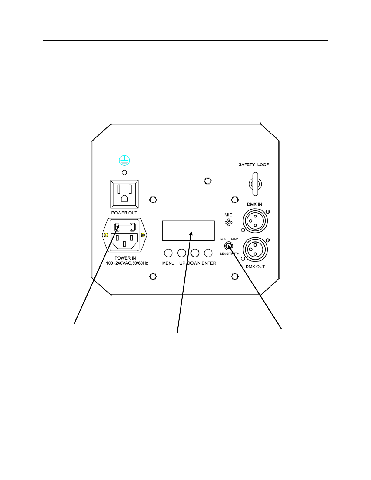
Product Overview
Fuse Holder
LED Display
Sound Sensitivity Knob
Back Panel
Radius™ 2.0 User Manual Rev. 2 Page 5 of 16
Page 6

Product Dimensions
Page 6 of 16 Radius™ 2.0 User Manual Rev. 2
Page 7

AC Power
ranging power supply and it can work with an input
(circuit breaker or fuse). Make
an appropriate electrical ground to avoid the risk of
a rheostat (variable resistor) or dimmer circuit, even
Fuse
Installed fuse
(held by plastic clip)
Spare fuse holder
(inside safety cap)
Safety cap
3. SETUP
The Radius™ 2.0 has an autovoltage range of 100~240 VAC, 50/60 Hz.
To determine the product’s power requirements (circuit breaker, power outlet, and
wiring), use the current value li sted on the label affixed to the product’s back panel, or
refer to the product’s specifications chart. The listed current rating indicates the
product’s average current draw under normal condition s.
Always connect the product to a protected circuit
sure the product has
electrocution or fire.
Never connect the product to
if the rheostat or dimmer channel serves only as a 0 to 100% switch.
Replacement
Follow the instructions below to change the fuse, if necessary.
Disconnect the product from the power outlet before replacing the fuse.
1. Wedge the tip of a flat-head screwdriver into the slot of the fuse holder.
2. Pry the fuse holder out of the housing.
3. Remove the blown fuse from the holder and replace wi th a fuse of the exact same
type and rating.
4. Insert the fus e holder ba ck in place and reconnect power.
The product does not ship with a spare fuse; however, the safety cap has room
for a spare.
Radius™ 2.0 User Manual Rev. 2 Page 7 of 16
Page 8

Power Linking
of the unit.
The power linking diagram shown above corresponds to the North American
in other markets, you must
consult with the local CHAUVET® distributor as power linking connectors and
1st Product
2nd Product
3rd Product
Other products
The product provides power linking via the IEC outl et loc ated in t he back
Please see the diagram below for further explanation.
Power Linking
Diagram
You can power link up to twenty (20) Radius™ 2.0 units on 120 VAC or up to
thirty-seven (37) Radius™ 2.0 units on 230 VAC.
version of the product ONLY! If using the product
requirements may differ in your country or region.
Page 8 of 16 Radius™ 2.0 User Manual Rev. 2
Page 9

Mounting
, read and follow the safety recommendations indicated in
may be mounted in any position; however, make sure adequate
Rigging
can support
section of this manual
Mount the
Bracke t Adjustment Kno b
Mounti ng Bracket
Before mounting the product
the Safety Notes section.
Orientation
The Radius™ 2.0
ventilation is provided around the product.
• Before deciding on a location for the product, always make sure there is easy
access to the product for ma intenance and programming purposes.
• Make sure that the structure onto which you are mounting the product
the product’s weig ht. Pleas e see the Technical Specifications
for weight information.
• When mounting the product overhead, always use a safety cable.
product securely to a rigging p oint , whether an elevated platf or m or a t russ.
• When rigging the product onto a truss, you should use a mounting clamp of
appropriate weight capacity. The bracket has a 13-mm hole, which is appropriate for
this purpos e.
• When power linking multiple products, you must al way s cons id er th e leng th of th e
power linking cable and mount the products close enough for th e cable to reach.
• The bracket adjustment knobs allow for directional adjustment when aiming the
product to the desired angle. Only loosen or tighten the bracket knobs manually.
Using t ools could damage the knobs.
Mounting Diagram
Radius™ 2.0 User Manual Rev. 2 Page 9 of 16
Page 10

Control Panel
located underneath the
on the control
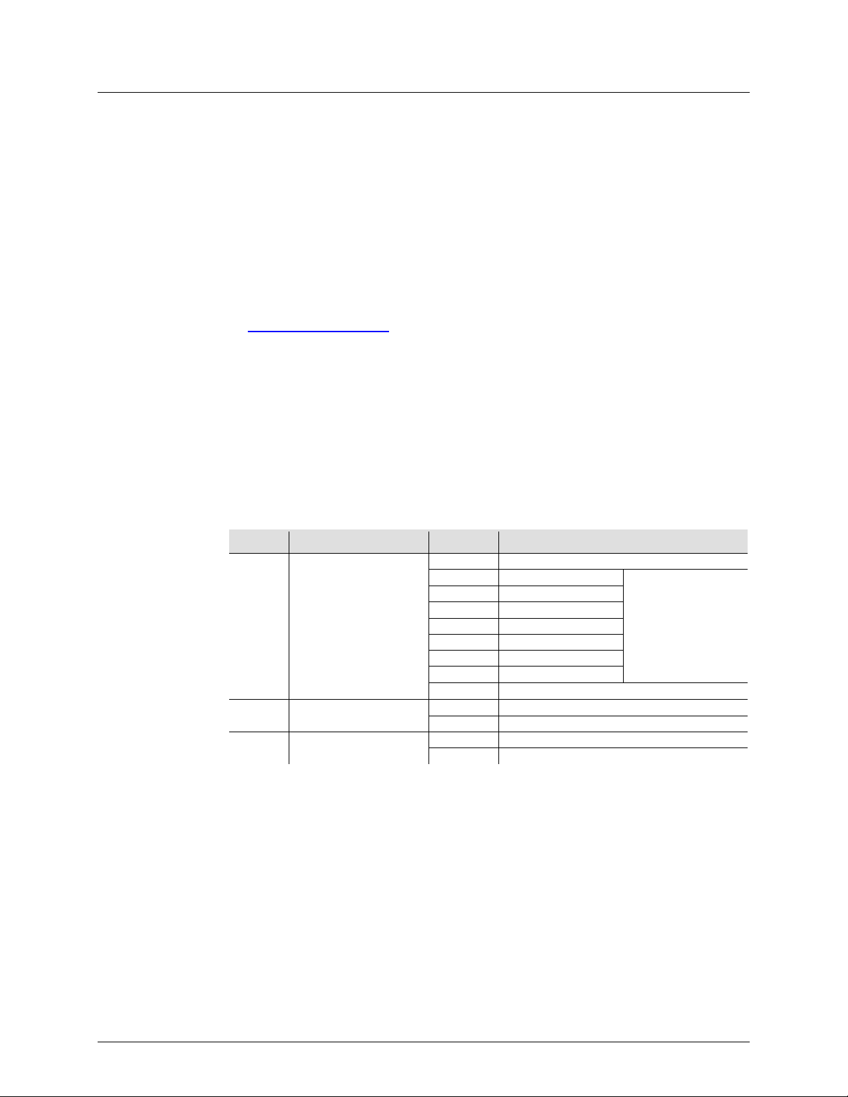
Menu Map
Mode
Programming Steps
Description
P1
P2
Gr een rotation
P6
P8
Color cycle rotation
Speed
Sound-Active
Mode
4. OPERATION
Operation
To access the control panel functions, use the four buttons
display. Pl ease r efer t o t he Product Overview to see the button locations
panel.
Button Function
<MENU>
<UP> Press t o scrol l up t he li st of opti ons or to find a higher valu e
<DOWN> Press t o scrol l down the list of options or to fi nd a low er value
<ENTER> Press to activate a menu option or a selected value
DMX Address 512 d__1-d512 Sets DMX starting address
Auto Programs P--
Press to find an operation mode or to back out of the current menu
option
Red rotation
P3 Blue rotation
P4 White rotation
P5 Amber rotation
All color rotation
P7 Al l color rotation and strobe
Auto Program
S-- S__1-S100 Sets aut o pro gram s peed
SNd Sets Sound-Active Mode
Page 10 of 16 Radius™ 2.0 User Manual Rev. 2
Page 11
Configuration
Starting
the selected DMX mode uses. I f you choose a starting address that is too high, you could
DMX Channel Assignments and Values
3-CH
000 ó 255
No function
000 ó 255
Red rotation
000 ó 255
Green rotation
000 ó 255
Blue rotation
000 ó 255
White r otat i on
000 ó 255
Am ber rotati on
000 ó 255
All color rotation
000 ó 255
Color cycle rotation
000 ó 255
Sound-Active
000 ó 255
No function
000 ó 255
0~100%
000 ó 255
No function
000 ó 255
0-30 Hz
Set the product in DMX mode t o control with a D M X cont rol ler.
(DMX)
1. Connect the product to a suitable po w er outlet .
2. Turn the product on.
3. Connect a DMX cabl e from the DMX out put of the DMX controll er to the DMX input
socket on the product.
Personalities
and
DMX
Address
The Radius™ 2.0 ha s a single 3-channel personality.
The Radius™ 2.0 uses up to 3 DMX channels in its high est DMX mode, which defines the
highest configurable address to 510.
Wh en selec ting a s tart ing DMX addres s, alw ays co nsider the num ber of DMX cha nnels
restrict the access to som e of the product’s channels.
If you are not familiar with the DMX protocol, download the DMX Primer from
www.chauvetlighting.com
.
To select the starting address, do the following:
1. Press <MENU> repeatedly unt i l 512 shows on the display.
2. Press <ENTER>.
3. Use <UP> or <DOWN> to sel ect t he st arting addres s.
4. Press <ENTER>.
Channel Function Value Setting
1 Auto Program s
2 Rotation
3 Strobe
Radius™ 2.0 User Manual Rev. 2 Page 11 of 16
Motor speed controlled
by Ch. 2
Page 12

Configuration
Automatic or
s in standalone
could interfere with the DM X signals from
Automatic Mode
Master/Slave
unit (the “master”) to control the
units (the “slaves”) without the need of a DMX
ate in Slave Mode. Once set and
all the slave units before connecting the master unit to the DMX
Never connect a DMX controller to a DM X string configured for Master/Slave
may interfere with the signals from the
(Standalone)
Set the product in one of the standalone modes to control without a DMX controller.
1. Connect the product to a suitable po w er outlet .
2. Turn the product on.
Never connect a product t hat is operating in any standalone mode (
Sound) t o a DMX string connected to a DMX controller. Product
mode may transmit DMX signal s that
the controller.
Sound-Active
To enable the Sound-Active mode, do the following:
Mode
1. Press <MENU> repeatedly unt i l SNd shows on t he display.
2. Press <ENTER>.
3. Turn the music on and adjust the microphone sensitivity knob until the product
starts responding to the beat of the music.
The product will only respond to low frequencies of music (bass and drums).
To enable the Automatic Mode, follow the instructions below:
1. Press <MENU> repeatedly unt i l P-- shows on the display.
2. Press <ENTER>.
3. Use <UP> or <DOWN> to choose from the different auto programs (P1-P8).
4. Press <ENTER>.
The Master/Slave mode allo ws a si ngle Radius™ 2.0
Mode
actions of one or more Radius™ 2.0
controller. The master unit will be set to operate in either Automatic or Sound-Active
mode, while the slave units will be set to oper
connected, the slave units will operate in unison with the master unit.
Configure the units as indicated below.
Slave un its:
1. Press <MENU> repeatedly unt i l 512 shows on the display.
2. Press <ENTER> to accept.
3. Set th e DMX address to 001.
4. Connect the DMX input of the first slave unit to the DMX output of the master unit.
5. Connect the DMX input of the subsequent slave units to the DMX output of the
previous slave uni t.
6. Finish setting and connecting all the slave units.
Master unit:
1. Set th e m aster unit to opera te i n either Automa t ic or Sound-Active mode.
2. Make the master unit the first unit in the DMX daisy chain.
• Configure
daisy chain.
•
operation because the controller
master unit.
• Do not connect more than 31 sl ave units to the master unit.
• The Radius™ 2.0 will not work in Master/Slave mode with the Radius™.
Page 12 of 16 Radius™ 2.0 User Manual Rev. 2
Page 13

Product
up reduces light output performance and can cause overheating. This can
To maintain optimum performance and
5. TECHNICAL INFORMATION
Dust build-
Maintenance
lead to reduction of the light source’s life.
minimi ze wear, you s hould clean your lighting products at least twice a month. However,
be aware that usage and environmental conditions could be contributing factors to
increase the cleaning frequency.
To clean the product, follow the instructions below:
• Unplug the product from po w er.
• Wait until the product is at room temperature.
• Use a vacuum (or dry compressed air) and a sof t brush to remov e dust collected on
the external surface/vents.
• Clean all transparent surfaces with a mild soap solution, ammonia-free glass
cleaner, or isopropyl alcohol.
• Apply the solution directly to a soft, lint-free cotton clot h or a lens cleaning t i ssu e.
• Wipe any dirt or grime to the outside edges of the transparent surfaces.
• Gently poli sh the transparent surfaces unti l t hey a re fr ee of haze and lint.
Alw ays dry th e transparent surfac es carefully after cleanin g them .
Radius™ 2.0 User Manual Rev. 2 Page 13 of 16
Page 14

General Troubleshooting
Excessive load on the circuit
Make sure that the total load does not
current
Short circuit along the power lines
Check the power lines and power cords
No energy on power outlet
Chec k power outl et
Change to another outlet
Loose or damaged power cord
Check the power cord
Blown fuse
Replace blown fuse with a good one of the
same type and rati ng
Internal problem
Send product for repair
Wrong starting address on the product
Set the correct starting address on the
Use the right fader(s) on the controller
Wrong DMX personality on the product
Set the c orrect DMX product ’ s personality
Assign the faders accordingly
Wrong p olarity s etting on t he DMX
controller
Change the si gnal polarity on the contr oller
Loose or damaged DMX cable
Chec k th e DMX cable before th e faul ty unit
Internal problem
Send product for repair
Signal cabl es are not D M X comp atib le
Replace non DMX cables with true DMX
cables
Interf erence wi th AC or radio signa l s
Keep DMX cables away from AC wires or
radio equipment
DMX cable too l ong
Install an optically coupled DMX amplifier
problems
Too many products connected
Install an optically coupled DMX amplifier
after unit #32
Terminator not connect ed
Install a terminator, as indicated in the DMX
Symptom Possible Cause Possible Acti on
Circuit breaker or fuse
keeps blowing
Product does not
power up
Product does not
respond to DMX
exceed 80% of the breaker or fuse n omi nal
product
Intermittent DMX
Problems
If you still experience problems after trying the solutions provided, contact
CHAUVET® Technical Support.
right before the product with intermittent
Primer section.
Page 14 of 16 Radius™ 2.0 User Manual Rev. 2
Page 15

Contact
CHAUVET®
Contact
Fax: +44 (0)1773 511110
Email: tech@chauvetlighting.com
www.chauvetlighting.com
www.chauvetlighting.co.uk
s to
Returning
to
Tech Support office and request a Return
. Be prepared to
provide the model number, serial number, and a brief description of the cause for the
, in its original box, and with its original packing
the following information on a piece of paper
properly. Any shi pping damage resulting from inadequate
reserves the right to use its own discretion to repair or replace
In case y ou need to return a product or request s upport, follow the procedure below:
Procedure
• If y ou li ve in t he U.S., contact CHAUVET® World Headquarters (see below).
• If y ou li ve in t he UK or I rel and, con tac t CHAUVE T® Europe Ltd.(see below).
• If you live in any other country, DO NOT contact CHAUVET®. Instead, contact your
distributor of record. Refer to our Web site for contact details of distributors outside
the U S, United Kingdom, or Ireland.
Information
Products
CHAUVET®
World Headquart ers
CHAUVET®
General Inform ation
Address: 5200 NW 108th Avenue
Sunrise, FL 33351
Voice: (954) 577-4455
Fax: (954) 929-5560
Toll free: (800) 762-1084
Technical Support
Voice: (954) 577-4455 (Press 4)
Fax: (954) 756-8015
World Wide Web
United Kingdom & Ireland
CHAUVET® Europe Ltd.
General Information
Address: Unit 1C
Brookhill Road Industrial Estate
Pinxton, Nottingham, UK
NG16 6NT
Voice: +44 (0)1773 511115
Technical Support
Email: uktech@chauvetlighting.com
World Wide Web
If you live outside the U.S., United Kingdom, or Ireland, contact your distributor of
record and follow their instructions on how to return CHAUVET® product
them. Visit our website for contact details.
Call the corresponding CHAUVET®
Merchandise Authorization (RMA) number before shipping the product
return.
You must send the merchandise prepaid
and accessories. CHAUVET® will not issue call tags.
Clearly label the package with the RMA number. CHAUVET® will refuse any product
returned without an RMA number.
Write the RMA number on a properly affixed label. DO NO T wr i t e th e RM A number
directly on the box.
Before sending the product, clea rly wr ite
and place it inside the box:
• Your name
• Your address
• Your phone number
• RMA number
• A brief description of the problem
Be su re to p ack th e product
packaging will be your responsibility. FedEx packing or double-boxing are
recommended.
CHAUVET®
returned product(s).
Radius™ 2.0 User Manual Rev. 2 Page 15 of 16
Page 16

Dimensions and
Length
Width
Height
Weight
10.5 in (268 mm)
13 in (330 mm)
9.6 in (243 mm)
6.3 lbs (2.8 kg)
Note: Dimensions in inches rounded to the nearest decimal digit.
Power
Power Supply Type
Range
Voltage Selection
Switching (internal)
100~240 V, 50/60 Hz
Auto-ranging
Parameter
120 V, 60 Hz
230 V, 50 Hz
Consumption
52 W
47 W
Operating
0.4 A
0.2 A
Power linking current (unit s )
8 A (20 units)
8 A (37 units)
Fuse
F 1 A, 250 V
F 1 A, 250 V
Power I / O
US/Worldwide
UK/Europe
Power input connector
IEC
IEC
Power output connector
Edison
IEC
Power Cord plug
Edison (US)
Local plug
Light Source
Type
Power
Lifespan
LED
3 W
50,000 h ours
Color
Quantity
Current
Red
1
730 mA
Green
1
730 mA
Blue
1
730 mA
White
1
730 mA
Amber
1
730 mA
Photo Optic
Parameter
Coverage angle
155º
Thermal
Maximum External Temp.
Cooling Syste m
104° F (40° C)
Convection
DMX
I/O Connectors
Connector Type
Channel Range
3-pin XLR
Sockets
3
Ordering
Product Name
Item Code
Item Numb er
Radius™ 2. 0
03050524
RADIUS20
6. TECHNICAL SPECIFICATIONS
Weight
Page 16 of 16 Radius™ 2.0 User Manual Rev. 2
 Loading...