

Page 1
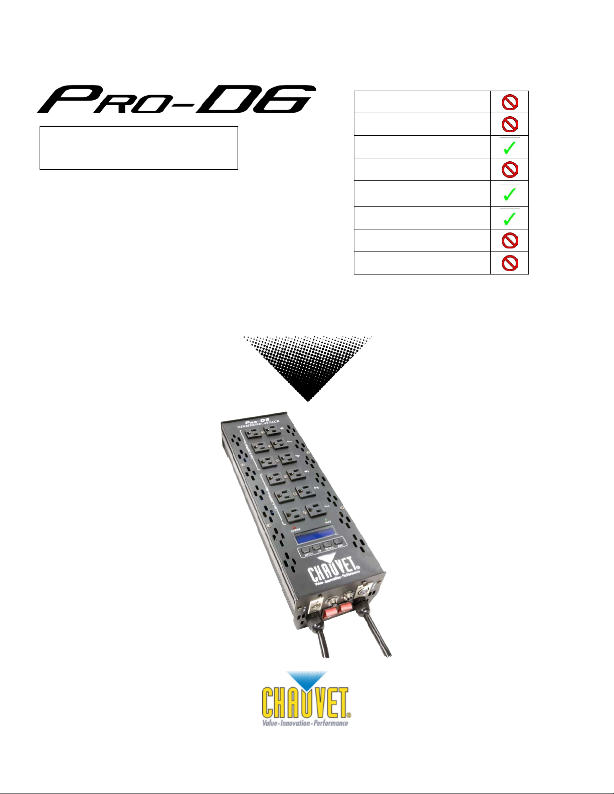
Snapshot
Auto-ranging
100~240 VAC, 50/60 Hz
There are 2 different versions of this product.
One version has a red LED display and the
other has a blue LC D displ ay.
Outdoor Use
Sound-Activated
DMX
Master/Slave
Circuit Breake r
User-Serviceable
Duty Cycle
User Manual
5200 NW 108th Avenue , Sunr ise, FL 33351 U.S.A.
(800) 762-1084 – (954) 577-4455
FAX (954) 929-5560
www.chauvetlighting.com
Page 2

TABLE OF CONTENTS
1. BE FORE YOU BEGIN............................................................................................................................................................ 3
WHAT IS INCLUDED ...................................................................................................................................................................... 3
UNPACKING INSTRUCTIONS ........................................................................................................................................................... 3
AC POWER ................................................................................................................................................................................ 3
SAFETY INSTRUCTIONS................................................................................................................................................................. 3
2. INTRODUCTION .................................................................................................................................................................... 4
FEATURES.................................................................................................................................................................................. 4
CONTROL FEATURES ..................................................................................................................................................... 4
ADDITIONAL FEATURES ................................................................................................................................................. 4
PRODUCT OVERVIEW ................................................................................................................................................................... 5
3. SETUP .................................................................................................................................................................................... 5
FIXTURE LINKING......................................................................................................................................................................... 6
Power connection .............................................................................................................................................................. 6
MOUNTING ................................................................................................................................................................................. 6
Orientation.......................................................................................................................................................................... 6
Rigging ............................................................................................................................................................................... 6
4. OPERAT I NG INSTRUCTIONS .............................................................................................................................................. 7
NAVIGATING THE CONTROL PANEL ................................................................................................................................................. 7
MENU FUNCTIONS ....................................................................................................................................................................... 7
USER CONFIGURATIONS ............................................................................................................................................................... 8
To set the DMX address .................................................................................................................................................... 8
5. APPENDIX .............................................................................................................................................................................. 9
GENERAL MAINTENANCE .............................................................................................................................................................. 9
General Troubleshooting ................................................................................................................................................... 9
RETURN PROCEDURE ................................................................................................................................................................ 10
CLAIMS .................................................................................................................................................................................... 10
TECHNICAL SPECIFICATIONS ....................................................................................................................................................... 11
CONTACT US ............................................................................................................................................................................ 11
Pro-D6 User Manual 2 Rev. 5
Page 3

1. BEFORE YOU BEGIN
Please read these instructions care fully, which include important
What is Included
Unpacking Instructions
Immediately upon receiving a fixture, carefully unpack the carton, check the contents to ensure that
all parts are present, an d have been rec ei ved in g ood condition. Notify the shipper immediately and
retain packing material for inspection if any parts appear damaged from shipping or the carton itself
shows signs of mishandling. Save the carton and all packing materials. In the event that a fixture
must be returned, it is im portant that the fixture be returned in the o riginal box and packing.
AC Pow er
To determine the power requirements for a particular fixture, see the label affixed to the back plate of
the fixture or refer to the fixture’s specifications chart. A fixture’s listed current rating is its average
current draw under normal conditions. All fixtures must be powered directly off a switched circuit and
cannot be run off a rheostat (variable resistor) or dimmer circuit, even if the rheostat or dimmer
channel is used solely for a 0% to 100% switch. Before applying power to a fixture, check that the
source voltage matches the fixture’s requirement. Check the fixture or device carefully to make sure
that if a voltage selection switch exis ts th at it is s et to th e c orr ec t line voltage you will use.
Warning! All fixtures must be connected to circuits with a suitable Earth Ground.
Notes! Input voltage equals outp ut voltage. Line A m ust be used when only one line is
nee ded in order for the unit t o function properly.
Safety Instructions
Ø 1 x Pro-D6
Ø 1 x Warranty Card
Ø 1 x User Manual
inform at i on ab ou t th e inst allation, usage and mai nt en ance of this
product.
• Please keep this User Guide for future consultation. If you sell the unit to another user, be sure that
they also receive this instruction booklet.
• This product is intended for indoor use only!
• To prevent risk of fire or shock, do n ot expose fixture to rain or mois t ure. Make sur e there are no
flamm abl e m at er i als cl os e t o the un it w hi l e op er ating.
• The unit mus t b e installed in a location with adequate ven ti l at i on, at least 20in (50cm) from adjacent
surfac es. Be sure that no ven t i l ati on slots are bloc k ed.
• Always disconnect from power source before servicing or replacing lamp or fuse and be sure to
replace with same lamp source.
• Secure fixture to fastening device using a safety chain. Never carry the fixture solely by the cables.
Use its carrying handles.
• Maximum ambient temperature (Ta) is 104° F (40° C). Do n ot op erate fixture at tem p eratures high er
than this.
• In the event of a s er i ous op erating problem, stop using the unit im m edi ately. Never tr y t o repair the
unit by yourself. Repairs carried out by unskilled people can lead to damage or malfunction. Please
contact the nearest authorized technical assistance center.
• Make sure the power cord is never crimped or damaged.
• Never disconnect the power cord by pulling or tugging on the cord.
Caution! There are no user-serviceable parts inside the unit. Do not open the housing or
attempt any repairs yourself. In the unlikely event your unit may require service,
please contact CHAUVET at: 954-577-4455.
Pro-D6 User Manual 3 Rev. 5
Page 4

2. INTRODUCTION
Features
CONTROL FEATURES
• 6-channel DMX-512 dimmer / relay pack
• Each channel can be set to any DMX address
• Each chan n el c an b e set as either dim m er or relay
• Variable electronic dimmer (0-100%)
ADDITIONAL FEATURES
• Dimmer curve selection for each channel: square, switch or linear
• Dual 20 A power lines (requires 2 separate circuits)
• Individual switch, circuit breaker and plug per line
• Accommodates different input voltages simultaneously
• 2 Edison plugs per channel
Pro-D6 User Manual 4 Rev. 5
Page 5

Product Overview
DMX Out
Line B
Line B
(Channels 4-6)
Line A
Circuit Breaker
Line B
Power Cord
DMX In
Line A
Power Switch
Line B
Power Switch
Line A
Line A
Power Cord
20 A Plug
Connection
(Channels 1-3)
Circuit Breaker
Pro-D6 User Manual 5 Rev. 5
Page 6

Hanging Clamp
Note!
Clamp is sold separately.
3. SETUP
Fixture Linking
You will n eed a serial data link to run light shows of on e or m ore fixtures usi ng a DM X-512 controller,
or to run synchronized shows on two or more fixtures set to a master/slave operating mode. The
combined number of channels required by all the fixtures on a serial data link determines the number
of fix ture s the data link can support.
Important: Fixtures on a serial data link must be daisy chained in one single line. To comply with the
Maximum recommended serial data link distance: 500 meters (1640 ft.)
Maximum r ec om m en d ed number of fixtu res on a serial d ata link: 32
To link fixtures together you must obtain data cables. You can purchase CHAUVET® certifi ed D M X
cables di r ect ly from a dealer/distribu t or or construct your own cable. If you choose to create your own
cable pl ease use data-gr ade cables that c an c arry a high qualit y si gn al an d are less pron e to
electromagnetic interference.
Power connection
The Pro-D6 has been designed to work on multiple input voltages (100-240VAV 50 / 6 0Hz)
simultaneously, and comes fitted with 20 amp connectors for this purpose. For example, Line A can
be plugg ed int o 120V and Lin e B can be pl ugged into 23 0V. Any voltag e bet w een 100-240 volts may
be used.
The power for the Line A and the Line B circuits must share the same electrical phase. The
unit will not operate properly if they are on different phases.
EIA-485 standard no more than 32 devices should be connected on one data link.
Connecting more than 32 fixtures on one serial data link without the use of a DMX
optically-isolated splitter may result in deterioration of the digital DMX signal.
Mounting
Orientation
This fi xtur e m ay b e m ount ed i n an y pos it i on provided th ere is adequate room for ventilation.
Rigging
It is important never to obs truct the fan or ven ts pat hway. Mount th e
fixture using, a suitable “C” or “O” type clamp. Adjust the angle of
the fixture by loosening both knobs and tilting the fixture. After finding the
desired position, retighten both knobs.
• When selecting installation location, take into consideration lamp
replacement access and routine maintenance.
• Safety cables must always be used.
• Never mount in places where the fixture will be exposed to rain, high
humidit y, extreme temp er at ur e ch anges or restr ic t ed ven t i l ation.
Pro-D6 User Manual 6 Rev. 5
Page 7

4. OPERATING INSTRUCTIONS
MAIN FUNCTION
SUB-FUNCTION
SELECTION
INSTRUCTION
Hold
Value=00.2s-20.0s
Prog1-12
Blackout
Start addr
Value=[001-512]
CH[01-06]
Value=[001-512]
Select a separate DMX address for each
channel
Select a pr eh eat p ercentage f or al l
channels
Value=[000-050%]
channel inde pendently
Select a maximum operation level for all
channels
Value=[000-100%]
channel inde pendently
(0/100%)
Manual l y man ip ul ate the output of all
channels simultaneously
Value=[000-100%]
channel inde pendently
Button
Function
Used to select and store the current menu
Scrolls through men u op tions in ascen di ng
Scrolls through men u op tions in desc end ing
<ESC>
Used to r et urn to a previous men u opt ion
DOWN
ESC
UP
MENU
Navigating the Control Panel
Access control panel functions using the four panel buttons located directly underneath the LCD Display.
Menu Functions
<MENU>
<UP>
<DOWN>
The Control Panel LCD Display shows the menu items you select from the menu map. When a menu
function is selected, the display will show immediately the first available option for the selected menu
function. To select a menu item, press <MENU>.
Pressing the <ESC> button will allow acc ess to the top of the menu map. Use the <UP> and
<DOWN> but t ons to navigat e the m en u m ap an d m enu options. Press the <MENU> button to access
the menu function currently displayed, or to enable a menu option. To return to the previous option or
menu without changing the value, press the <ESC> button.
or option wi th in a m enu
order
order
DMX fail
DMX address
Preheat
Max level
Curve
Manual
Speed time
Block
Single
ALL [000-050%]
Single
ALL [000-100%]
Single
ALL SWITCH-LINEAR
Single
ALL [000-100%]
Single
CHAN[01-06]
CHAN[01-06]
CHAN[01-06]
SWITCH-LINEAR
CHAN[01-06]
Select how the product will react if there is
no DMX detected
Select a DMX starting address
Select a pr eh eat p ercentage for each
Select a maximum operation level for each
Selec t operat ion mode for all channels:
dimmer (0-100%) or relay (0/100%)
Select op eration mod e f or eac h c h ann el
indepen d ently: dimm er (0-100%) or relay
Manual l y man ip ul ate the output of each
Pro-D6 User Manual 7 Rev. 5
Page 8

User Configurations
To set the DMX address
1) Select “DMX address” by pressing <Menu>, then the <Up/Down> buttons, until the di s play
reads correctly.
2) Press <Menu> to reach the second step of the addressing menu.
3) Use the <Up/Down> buttons to select Block or Single m od e.
4) P ress the <Menu> button.
5) Use the <Up/Down> buttons to select the correct value. Once you are satis f i ed wit h you r inp ut,
press <Menu>to confirm your selection.
6) Pressing the <Esc> button will allow you to back out of this menu. This is useful if you wish to
select th e opt ion for setting eac h channel to a dif f er ent dm x add ress.
Pro-D6 User Manual 8 Rev. 5
Page 9

5. APPENDIX
Applies to
Foggers
Dimmers
Auto shut off
Chec k fan thermal switch res et
ü
Breaker/Fuse keeps
blowing
Check total load placed on device
Chase is too slow
Check users manual for speed adjustment
ü ü
ü
Device has no power
Check for power on Mains.
Chec k device’s fuse. ( internal a nd/or external)
ü ü
ü
Fixture is not
Check DMX Dip switch settings for correct addressing
Check polarity switch settings
Fixture is on but
audio
Make sure you have the correct audio mode on the
Adjust sound sensitivity knob
Loss of signal
Use o nly DMX cables
or black lights.
Relay will not work
Check circ uit breaker r eset switch
Check cable connections
ü
General Maintenance
To maint ain op t i mu m p erformance and minimize wear, fixtures should be cleaned frequently. Usage
and environment are contributing factors in determining cleaning frequency. As a general ru l e,
fixtures sh ould be cleaned at least twic e a month. Dust build up reduc es lig ht out p ut p er f or m ance and
can caus e overheating . T his c an l ead t o r educed lamp lif e and inc reased mech anical wear. Be sure
to power of f the fi xture before c ond uc ting maint en ance.
Unplug the fixtur e fr om p ower . Use a vacuum or air c om pressor and a sof t brus h to remove dus t
collect ed on ext ernal vents and int er n al c om p onents. Clean all glass wh en th e fixture is cold with a
mild solution of glass cleaner or Isopropyl Alcohol and a soft lint free cotton cloth or lens tissue. Apply
solution to the cloth or tissue and drag dirt and grime to the outside of the lens. Gently polish optical
surfac es un til they are fr ee of h az e and li nt .
The clean in g of internal and ext er n al op t ical lenses and/or mirr ors m u s t b e c arried out periodically to
optimi z e ligh t output. Clean i ng frequenc y depends on the environment in which the fixture operates:
damp, smoky or particularly dirty surrounding can cause greater accumulation of dirt on the unit’s
optics. Clean with soft cloth using normal glass cleaning fluid. - Always dry the parts carefully. - Clean
the external optics at leas t e very 20 days. Cl ean the internal opt ics at least every 30/60 days .
General Troubleshooting
Symptom Solution(s)
responding
there is n o
movement to the
Chec k DMX cables
control switches. If audio provided via ¼” jack, make
sure a liv e audio signal exis ts
Install terminator
Note: Keep DMX cables separated from power cables
If you still have a problem after trying the above solutions, please contact CHAUVET Technical
Support at the locati on on the ne xt pag e.
Lights
& Snow Controllers
ü
ü
ü ü
& Chaser
ü ü ü ü
ü
Pro-D6 User Manual 9 Rev. 5
Page 10

Return Procedure
Return ed m erc handise mus t b e s ent pr epaid and in the original packing; call tags will not be issued.
Package must be clearly labeled with a Return Merchandise Authorization Number (RMA #).
Products returned without an RMA # will be refused. Call CHAUVET and request an RMA # before
shippi ng th e fixture. Be pr ep ared to provid e th e m od el nu m b er, s eri al nu mb er an d a brief descrip ti on
of the cause for the return. Be sure to properly pack fixture, any shipping damage resulting from
inadequate packaging is the customer’s responsibility. As a suggestion, proper UPS packin g or
double-boxing is always a safe method to use. CHAUVET reser v es t he right to use its ow n dis c r et i on
to repair or r epl ac e product(s).
Note: If you are given an RMA #, please include the following information on a piece of
paper inside the box:
1) Your name
2) Your address
3) Your phone number
4) RMA #
5) A brief description of the symptoms
Claims
Damage inc urred during shipping is the responsibility of the shipper; therefore, the d am ag e mus t b e
reported to the carrier upon receipt of merchandise. It is the customer's responsibility to notify and
submit claims with the shipper in the event that a fixture is damaged during shipp ing. Any other cla im
for items suc h as mis s i ng c om ponent/p art , d am ag e not related to sh ipping, an d c oncealed dam ag e,
must be m ad e wit hi n s even ( 7) d ays of r ec ei vi ng m er c h an dise.
Pro-D6 User Manual 10 Rev. 5
Page 11

Technical Specifications
WEIGHT & DIMENSIONS
Length ................................................................................................................................. 18 in (457 mm)
Width .................................................................................................................................. 5.8 in (147 mm)
Height ................................................................................................................................... 3.8 in (97 mm)
Weight .................................................................................................................................. 9.3 lbs (4.2 kg)
POWER
Auto-ranging (in put voltage equ als out pu t vol t ag e) ................................................ 100-240VAC 50/60Hz
Maximum power output (per channel) .................................................................................................. 10A
Circuit breaker (Line A) ......................................................................................................................... 20A
Circuit breaker (Line B) ......................................................................................................................... 20A
Maximum load ....................................................................................................................................... 40A
THERMAL
Maximum ambient temperature .............................................................................................104°F (40°C)
CONTROL & PROGRAMMING
Data input ................................................................................................... locking 3-pin XLR mal e s ock et
Data out put ............................................................................................. locking 3-pin XLR female socket
Data pin configuration................................................................................. pin 1 shield, pin 2 (-) , pi n 3 ( +)
Protocols ........................................................................................................................... DMX-512 USITT
ORDERING INFORMATION
Pro-D6 ............................................................................................................................................. PROD6
WARRANTY INFORMATION
Warranty.................................................................................................................. 2-year limited warranty
The power for the Line A and the Line B circuits must share the same electrical phase. The
unit will not operate properly if they are on different phases.
Contact Us
World Wide
General Inform ation CHAUVET
Technica l Supp ort CHAUVET
World Wide Web www.chauvetlighting.com
Pro-D6 User Manual 11 Rev. 5
5200 NW 108th Avenue
Sunrise, FL 33351
voice: 954.577.4455
fax: 954.929.5560
toll free: 800.762.1084
5200 NW 108th Avenue
Sunrise, FL 33351
voice: 954.577.4455 (Pr e ss 4)
fax: 954.929.5560 (Attention: Service)
 Loading...