How it Works
Log In / Sign Up
Buy Points
How it Works
FAQ
Contact Us
Questions and Suggestions
Users
Champion
Loading...
S
STE 1650
4
STT1170E
2
STT1170Е
2
T
T 221
2
T 233
2
T 252
T256
2
T 262
2
T 263
2
T 266
2
T275
T275-2
T276
T 333
T334FS
2
T336
2
T 337
2
T345
T345-2
T346
T347-2
T374FS
2
T394FS-2
T433-2
T 436
2
T 437
2
T446
T447-2
T 516
2
T 517
2
T 523S-2
Taskmaster PP-3
2
TB360
2
Tri-Fuel
TUW
TUW-15
2
Two Tank
Two Tank w/Prewash
U
U-BW
2
UC-C
3
UC-CW
4
UC-CW-M1
U-H1
3
UH-100
9
UH-100B
10
UH130
2
UH130B
4
UH130B M4
UH130 M4
UH-150
3
UH-150B
2
UH-170
7
UH-170B
7
UH-200
11
UH-200B
8
UH230
UH230B
2
UH230B M4
UH230 M4
UH330 ADA
2
UH330B
UH330B M4
U-HB
2
UL-100
10
UL-130
4
UL130 M4
UL-150
3
U-LD
2
UltraCOOL CP18
UltraCOOL CP20
Ultracool CP25
2
UltraCool CP 35
UltraCool CP 70
2
US-72
USN-10
4
USN-72
3
USN72-135
USN72-185
USN72-250
USN72-60
USN72-85
UTC-6
UTL
2
UTM-10
V
Valu-Clean VC1000
Valu-CleanVC1000HT
VC1000
Versa-Clean
W
W-6
W-6-WS
WC 35
2
WC37
2
WC44
3
WC46
3
WC50
3
WCM28
2
W-DH
2
WheelyBird
WHEELYBIRD 40909
WOBBLE BIRD
Loading...
Loading...
Nothing found
UH-170B
Brochure & Specs
7 pgs
2.98 Mb
0
Installation & Operation Manual
106 pgs
8.36 Mb
0
Installation And Operation Manual
106 pgs
7.98 Mb
0
Installation Manual
84 pgs
6.44 Mb
0
Installation/operation Manual With Service Replacement Parts
106 pgs
16.34 Mb
0
Operation Manual
106 pgs
8.33 Mb
0
User Manual
2 pgs
373.56 Kb
0
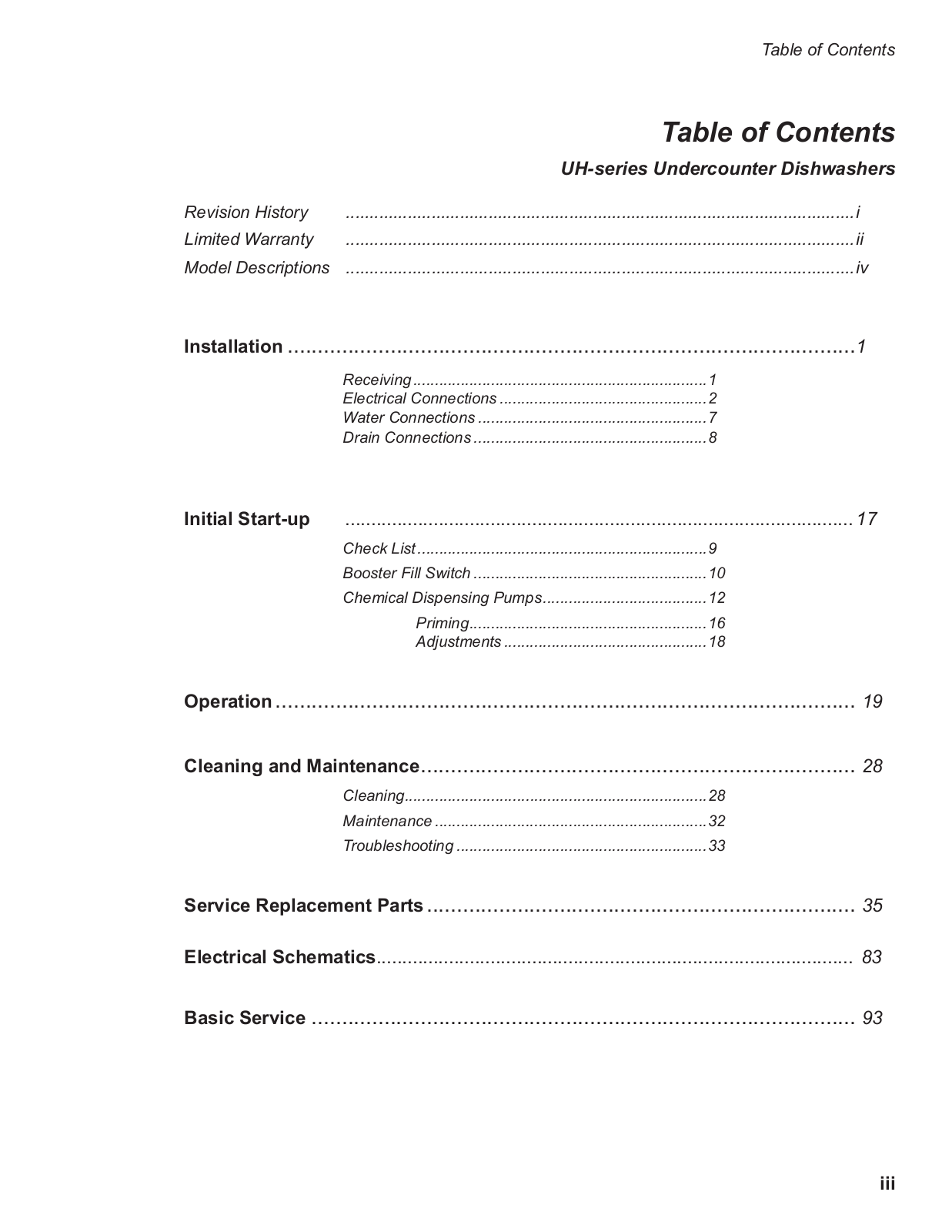
Table of contents
Loading...
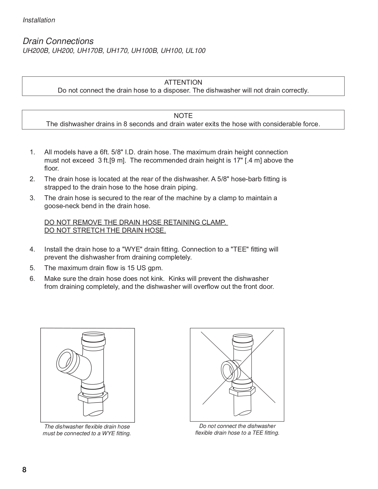
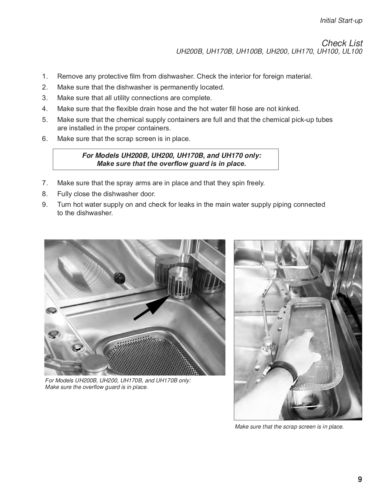
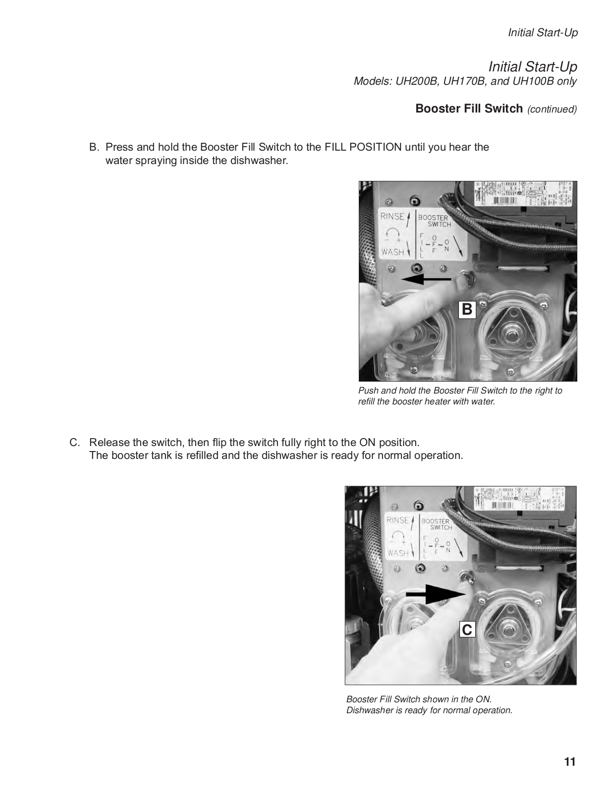
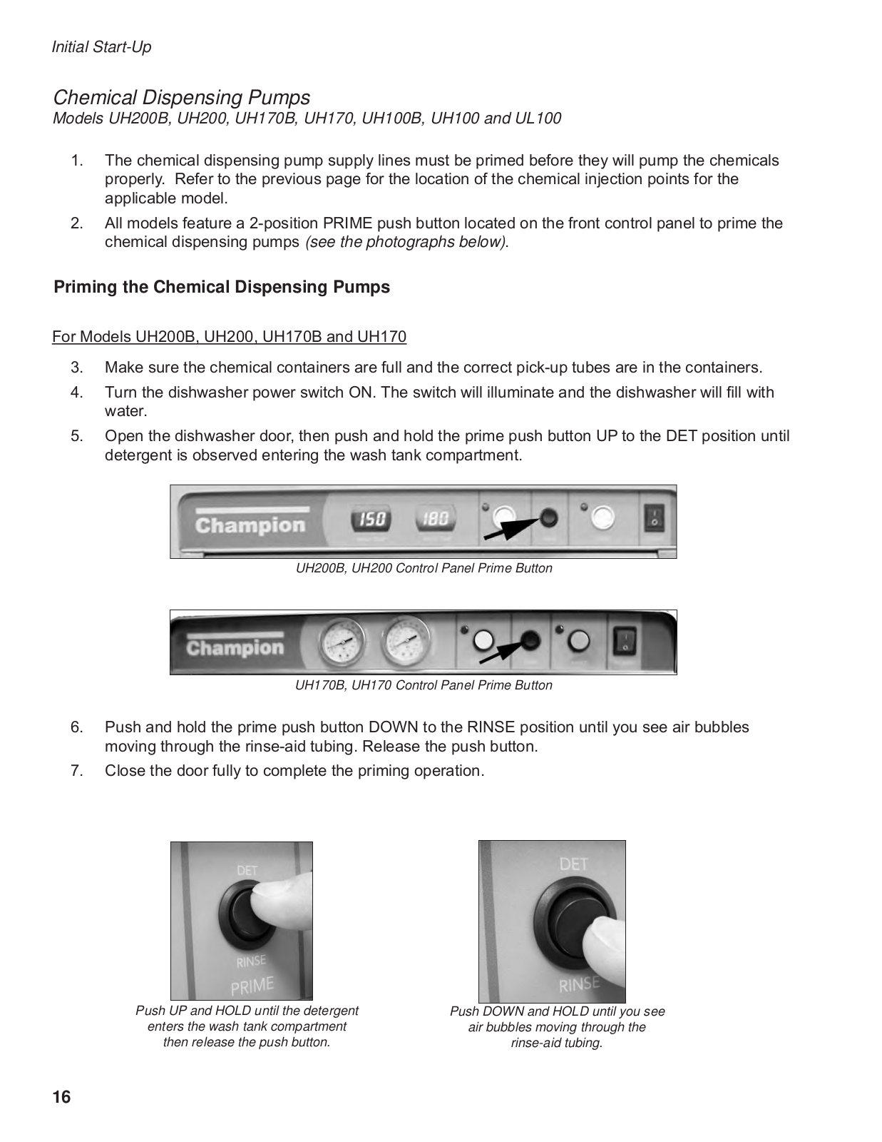
Champion UH-170B, UH-170 Operation Manual
...
Champion Operation Manual
Download
Specifications and Main Features
Frequently Asked Questions
User Manual
Download
Loading...
+
76
hidden pages
Unhide
You need points to download manuals.
1 point = 1 manual.
You can buy points or you can get point for every manual you upload.
Buy points
Upload your manuals