


Technical Manual
Upright Conveyor
Dishwasher
M1
Model
UC-CW
30" Conveyor
July, 2003
P.O. Box 4149
Winston-Salem, North Carolina 27115-4149
336/661-1556 Fax: 336/661-1660
Manual P/N 113160 Rev. F
Machine Serial No.
www.championindustries.com
2674 N. Service Road
Jordan Station, Ontario, Canada L0R 1S0
905/562-4195 Fax: 905/562-4618
For machines beginning with Serial no. 89788
pion
Champion
Cham
Champion
Champion
Champion
Champion
Champion
Champion

Complete the information below so it will be available for quick reference.
Model Number __________________________ Serial Number________________________
Voltage and Phase ______________________________________________________________
Champion Parts Distributor __________________________________ Phone _____________
_____________________________________________________________________________
Champion Service Agency___________________________________ Phone _____________
_____________________________________________________________________________
Champion (USA) Champion (Canada)
National Service Department National Service Department
Phone: 1(800) 858-4477 Phone: 1(800) 263-5798
Fax: 1(336) 661-1660 Fax: 1(905) 562-4618
NOTE: When calling to order parts, be sure to have the model number,
serial number, voltage, and phase of your machine.
Machine Data Plate with
Model No., Serial No.,
Voltage and Phase is
located on the right or left
side of the Control Cabinet
Top of Machine
Control Cabinet
Left to Right
Model Shown
COPYRIGHT © 2003 by Champion Industries, Inc.

Revision History
Revision Revised Serial Number Comments
Date Pages Effectivity
03/10/00 All 89788 Reissue of manual and new replacement parts lists.
07/09/01 89 J1436 Added P/N 325838 overflow to Prewash Section.
07/09/01 44 J1436 Added P/N 113291 float switch to Wash and Rinse
Section.
07/09/01 47 — Changed P/N 110854 to 111019 to Econorinse Section.
07/09/01 79 — Added 480V 95KW element to booster.
11/29/01 80
— Revised bubble numbers on drawing
11/29/01 82
— Changed P/N 105840 to 105841 on Steam Booster
11/29/01 84 — Revised bubble numbers on drawings
01/03/02 40, 44, 47 J1534 Change vacuum breaker 1/2" 100500 to 113220
01/03/02 53 J1534 Change vacuum breaker 3/4" 104429 to 113222
01/03/02 79 J1534 Added GC 1/2" solenoid valve 113352
and repair kit 113392
4/30/02 40 Corrected float switch 110854 to 111019
05/22/02 40, 44, 47 Added 900836 Kit*Repair 1/4" & 1/2"
Vacuum Breaker
05/22/02 53 Added 900837 Kit*Repair 3/4" Vacuum Breaker
2/5/03 39, 43, 47 Replaced P/N 108391 with 113622 thermometer.
2/5/03 67 Replaced impellers with new part numbers.
2/5/03 93, 97 Replaced Furnace (Siemens) overloads with
Telemecanique (Square D) overloads.
7/23/03 40, 44, 47, 53 Revised plastic style vacuum breakers with bronze style.
i
REVISIONS

ii
WARRANTY
LIMITED WARRANTY
Champion Industries Inc. (herein referred to as Champion), P.O. Box 4149, Winston-Salem, North Carolina 27115,
and P.O. Box 301, 2674 N. Service Road, Jordan Station, Canada, L0R 1S0 , warrants machines, and parts, as set out
below.
Warranty of Machines: Champion warrants all new machines of its manufacture bearing the name “Champion” and
installed within the United States and Canada to be free from defects in material and workmanship for a period
of one (1) year after the date of installation or fifteen (15) months after the date of shipment by Champion,
whichever occurs first. [See below for special provisions relating to glasswashers.] The warranty registration
card must be returned to Champion within ten (10) days after installation. If warranty card is not returned to
Champion within such period, the warranty will expire after one year from the date of shipment.
Champion will not assume any responsibility for extra costs for installation in any area where there are
jurisdictional problems with local trades or unions.
If a defect in workmanship or material is found to exist within the warranty period, Champion, at its election,
will either repair or replace the defective machine or accept return of the machine for full credit; provided, however, as to glasswashers, Champion’s obligation with respect to labor associated with any repairs shall end
(a) 120 days after shipment, or (b) 90 days after installation, whichever occurs first. In the event that Champion
elects to repair, the labor and work to be performed in connection with the warranty shall be done during regular
working hours by a Champion authorized service technician. Defective parts become the property of Champion.
Use of replacement parts not authorized by Champion will relieve Champion of all further liability in connection
with its warranty. In no event will Champion’s warranty obligation exceed Champion’s charge for the machine.
The following are not covered by Champion’s warranty:
a. Lighting of gas pilots or burners.
b. Cleaning of gas lines.
c. Replacement of fuses or resetting of overload breakers.
d. Adjustment of thermostats.
e. Adjustment of clutches.
f. Opening or closing of utility supply valves or switching of electrical supply current.
g. Cleaning of valves, strainers, screens, nozzles, or spray pipes.
h. Performance of regular maintenance and cleaning as outlined in operator’s guide.
i. Damages resulting from water conditions, accidents, alterations, improper use, abuse,
tampering, improper installation, or failure to follow maintenance and operation procedures.
j. Wear on Pulper cutter blocks, pulse vanes, and auger brush.
Examples of the defects not covered by warranty include, but are not limited to: (1) Damage to the exterior or
interior finish as a result of the above, (2) Use with utility service other than that designated on the rating plate,
(3) Improper connection to utility service, (4) Inadequate or excessive water pressure, (5) Corrosion from
chemicals dispensed in excess of recommended concentrations, (6) Failure of electrical components due to
connection of chemical dispensing equipment installed by others, (7) Leaks or damage resulting from such
leaks caused by the installer, including those at machine table connections or by connection of chemical
dispensing equipment installed by others, (8) Failure to comply with local building codes, (9) Damage caused by
labor dispute.
Warranty of Parts: Champion warrants all new machine parts produced or authorized by Champion to be free
from defects in material and workmanship for a period of 90 days from date of invoice. If any defect in
material and workmanship is found to exist within the warranty period Champion will replace the defective
part without charge.
DISCLAIMER OF WARRANTIES AND LIMITATIONS OF LIABILITY
. CHAMPION’S WARRANTY
IS ONLY TO THE EXTENT REFLECTED ABOVE. CHAMPION MAKES NO OTHER WARRANTIES,
EXPRESS OR IMPLIED, INCLUDING, BUT NOT LIMITED, TO ANY WARRANTY OF
MERCHANTABILITY, OR FITNESS OF PURPOSE. CHAMPION SHALL NOT BE LIABLE FOR
INCIDENTAL OR CONSEQUENTIAL DAMAGES. THE REMEDIES SET OUT ABOVE ARE
THE EXCLUSIVE REMEDIES FOR ANY DEFECTS FOUND TO EXIST IN CHAMPION DISHWASHING
MACHINES AND CHAMPION PARTS, AND ALL OTHER REMEDIES ARE EXCLUDED,
INCLUDING ANY LIABILITY FOR INCIDENTALS OR CONSEQUENTIAL DAMAGES.
Champion does not authorize any other person, including persons who deal in Champion dishwashing
machines to change this warranty or create any other obligation in connection with Champion Dishwashing Machines.

iii
CONTENTS
CONTENTS
Page
WARRANTY ............................................................................................................................. ii
INTRODUCTION...................................................................................................................... 1
GENERAL................................................................................................................................. 2
Components and Features.................................................................................................... 2
Options................................................................................................................................. 3
Modular Sections (Details and Dimensions)....................................................................... 4
INSTALLATION........................................................................................................................ 5
Unpacking............................................................................................................................ 5
Locating............................................................................................................................... 5
Assembling the Sections...................................................................................................... 5
Assembling the Conveyor Belt............................................................................................ 6
Completing the Assembly ................................................................................................... 7
Installing the Optional Blower Dryer (Steam or Electric).................................................. 7
Plumbing Connections......................................................................................................... 8
Electrical Connections......................................................................................................... 8
Ventilation Connections....................................................................................................... 9
Machine Vent Damper Settings........................................................................................... 9
Chemical Connections......................................................................................................... 9
INITIAL START UP .................................................................................................................. 10
Baffles.................................................................................................................................. 10
Thermometers...................................................................................................................... 10
Conveyor Shut-off Shelf...................................................................................................... 11
Conveyor Belt Drive Clutch Adjustment ............................................................................ 11
Conveyor Belt Alignment.................................................................................................... 11
Energy Sentinel (Idle pump shut-off).................................................................................. 11
OPERATION.............................................................................................................................. 12
Operation Steps.................................................................................................................... 12
Curtain Placement................................................................................................................ 12
MAINTENANCE....................................................................................................................... 15
Maintenance Schedule......................................................................................................... 15
Cleaning............................................................................................................................... 15
Lubrication........................................................................................................................... 16
Operation Checks ................................................................................................................16
Deliming.............................................................................................................................. 17

iv
CONTENTS
Page
TROUBLESHOOTING ............................................................................................................. 18
BASIC SERVICE ....................................................................................................................... 21
Electrical Service................................................................................................................. 22
Fuse Blocks—120VAC Control Voltage....................................................................... 24
Motor Starter Overloads................................................................................................ 24
Pump Timer and Final Rinse Timer .............................................................................. 25
Electric Eye Energy Sentinel System ........................................................................... 26
Automatic Fill/Low Water Heat Protection .................................................................. 28
Thermostat Locations and Adjustments ....................................................................... 31
Motors........................................................................................................................... 32
Mechanical Service..............................................................................................................33
Pump Seal Replacement ............................................................................................... 33
Cross Flow Elbow Adjustment..................................................................................... 34
Solenoid Valve Repair................................................................................................... 34
REPLACEMENT PARTS.......................................................................................................... 35
WIRING DIAGRAMS...............................................................................................................105
ELECTRICAL SCHEMATICS ................................................................................................. 110
LIST OF FIGURES
Figure 1—Component Locator.................................................................................................. 2
Figure 2—Control Cabinet Chemical Connections................................................................... 9
Figure 3—Baffle Locations........................................................................................................ 10
Figure 4—Conveyor Belt Drive Clutch ..................................................................................... 11
Figure 5—Conveyor Belt Alignment......................................................................................... 11
Figure 6—Curtain Placement..................................................................................................... 12
Figure 7—Auto Fill Operation................................................................................................... 12
Figure 8—Fresh Water Make-up ............................................................................................... 14
Figure 9—Fuse Blocks............................................................................................................... 24
Figure 10—Motor Starter Overloads......................................................................................... 24
Figure 11—Pump Timer and Final Rinse Timer ....................................................................... 25
Figure 12—Electric Eye Location ............................................................................................. 26
Figure 13—Sensor Mounting..................................................................................................... 26
Figure 14—Bypass Switch.........................................................................................................27
Figure 15—Electric Eye Indicator Lights.................................................................................. 27
Figure 16—Dual Float Switch Assembly.................................................................................. 28
Figure 17—Dual Float Troubleshooting Diagram..................................................................... 30
Figure 18—Electric Tank Heat Thermostats ............................................................................. 31
Figure 19—Electric Booster Thermostats ................................................................................. 31

v
CONTENTS
Page
Figure 20—Booster High Limit ................................................................................................. 31
Figure 21—Motor Wiring Connections ..................................................................................... 32
Figure 22—Pump Seal Replacement......................................................................................... 33
Figure 23—Cross Flow Elbow................................................................................................... 34
Figure 24—Parker Solenoid Valve............................................................................................. 34
Figure 25—Asco Solenoid Valve............................................................................................... 34
Figure 26—Load Section........................................................................................................... 36
Figure 27—Prewash Section...................................................................................................... 38
Figure 28—Wash/Rinse Section ................................................................................................ 42
Figure 29—EconoRinse Section (Optional).............................................................................. 46
Figure 30—EconoRinse Pumped & Final Rinse Spray Arms................................................... 48
Figure 31—Unload Section ....................................................................................................... 52
Figure 32—Drive Shaft Assembly............................................................................................. 54
Figure 33—Conveyor Drive and Shut-off.................................................................................. 56
Figure 34—Baffles and Back Flow Piping................................................................................ 58
Figure 35—Peg Belt................................................................................................................... 60
Figure 36—Peg Belt with Upper Rod........................................................................................ 60
Figure 37—Flat Belt .................................................................................................................. 62
Figure 38—Insulated Tray Belt and (Optional Silverware Belt)............................................... 62
Figure 39—Stainless Steel Peg Belt.......................................................................................... 64
Figure 40—Pump Assembly...................................................................................................... 66
Figure 41—Electric Tank Heat .................................................................................................. 70
Figure 42—Steam Tank Heat..................................................................................................... 74
Figure 43—Steam Coils (Low Pressure/Standard Pressure)..................................................... 76
Figure 44—Electric Booster ......................................................................................................78
Figure 45—Steam Booster ........................................................................................................80
Figure 46—Steam Booster 40° Rise .......................................................................................... 84
Figure 47—Steam Booster 40° Rise Low Pressure Only.......................................................... 88
Figure 48—Control Cabinet.......................................................................................................92
Figure 49—Blower Dryer (Optional) ........................................................................................ 96
Figure 50—Control Panel, Electric Booster.............................................................................. 98
Figure 51—Wiring Diagram 57KW Electric Booster...............................................................110
Figure 52 —Wiring Diagram 63KW Electric Booster...............................................................111
Figure 53—Wiring Diagram 72KW Electric Booster...............................................................112
Figure 54 —Wiring Diagram 81KW Electric Booster...............................................................113
Figure 55—Wiring Diagram Electric Tank Heat.......................................................................114

vi
CONTENTS
ELECTRICAL SCHEMATICS
B701669—Wiring Diagram (UCCW-2T, Steam/Electric)
(Beginning with Serial Number 89788)
B701670—Wiring Diagram (UC-1T, Steam/Electric)
(Beginning with Serial Number 89788)
B701512—Wiring Diagram (UCCW-3T, Steam/Electric)
(Beginning with Serial Number 89788)
B701559—Wiring Diagram (UCCW-4T-WS, Steam/Electric)
(Beginning with Serial Number 89788)
B701399—Wiring Diagram (UC Tank Heat/Electric)
(Beginning with Serial Number 89788)
APPENDIXES
Appendix A—UC-CW EconoRinse Section....................................................................... 103
Appendix B—Door Safety Switch and Magnet Mounting.................................................104
Appendix C—Cross Flow Elbow Adjustments ................................................................... 105

INTRODUCTION
Welcome to Champion...
and thank you for allowing us to take care of your dishwashing needs.
This manual covers the basic Upright Conveyor Dishwasher model UC-CW.
Your machine was completely assembled, inspected, and thoroughly tested at our factory. Then
it was disassembled and crated in sections for delivery to your installation site.
The reassembly and installation of your machine is performed by others. However, Champion
can arrange for an Authorized Champion Service Agency to super
vise the reassembly and
installation. Electrical wiring and plumbing services, including final connections to the machine
are supplied by others.
This manual contains:
• Warranty information
• Installation and operation procedures
• Maintenance instructions
• Troubleshooting guide
• Basic service information
• Replacement parts lists
• Wiring diagrams and electrical schematics
Complete and return your warranty registration card immediately after the installation of your
machine.
All information, illustrations and specifications contained in this manual are based upon the
latest product information available at the time of publication. Champion constantly improves
its products and reserves the right to make changes at any time or to change specifications or
design without notice and without incurring obligation.
For your protection, factory authorized parts should always be used for repairs.
Replacement parts may be ordered from your Champion authorized parts distributor or from
your Champion authorized service agency.* When ordering parts, please supply the model
number, serial number, voltage, and phase of your machine.
*Champion can only ship parts to customers by VISA or MasterCard at list price.
1
INTRODUCTION
GENERAL
Components and Features
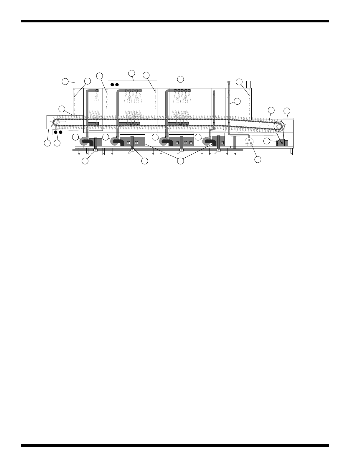
Major Components
The major components of the UC-CW upright conveyor dishwashing machines are listed in
Figure 1.
1. Ball drain valve 11. Peg belt (30" for UC-CW)
2. Load end push button Start-Stop station 12. Sliding conveyor shut-off shelf
3. Load end Recirculating flushing nozzles 13. Conveyor drive assembly
4. Electric Eyes-Energy Sentinel (idle pump shut-off) 14. Optional steam or electric booster
5. Vent openings with 7" stainless steel stacks 15. Steam coil/injectors or electric tank heat
6. Load Section-Long Curtain 16. Low water tank heat protection float switches
7. Prewash Section-Short Curtain 17. High Pressure recirculating pumps
8. Wash Section-Short Curtain 18. Top-mounted control cabinet
9. Unload Section-Long Curtain 19. Automatic Fill
10. Final Rinse Piping
The UC-CW Upright Conveyor is a fully automatic dishwashing machine consisting of modular
sections. Each section is available in a choice of lengths to satisfy your specific space and
warewashing requirements. Champion’s ability to custom build your machine to meet your
application gives you the most powerful and versatile dishwashing machine on the market today.
Standard Features
• All models are constructed of heavy-gauge stainless steel including the panels, base, legs, and feet.
• All Models are available for either Right to Left or Left to Right operation.
• All models are high temperature (180°F final rinse) sanitizing machines.
• All Models have a single common water connection and a single common electrical connection.
(A separate electrical connection is required for an optional electric booster or blower dryer).
• All models have chemical dispensing equipment connection provisions inside the control cabinet.
• Standard Voltages are available in: 208/60/3 240/60/3 460/60/3
For non-standard voltages please consult the factory.
2
GENERAL
Figure 1
Left to Right Machine
18
7
5
4
6
8
19
10
9
11
12
23
171717
15161
17
13
14

Options
Your machine may be equipped with one or more of the following options:
• Auto fill with drain interlock
• Stainless steel back panel
• Conveyor Belts
- Flat belt
- Cup belt
- Thermal tray belt
- Silverware belt (with or without riser)
- Belts with upper rods
- or any combination of the above.
• Blower-dryer, steam or electric (Minimum 9 foot unload required)
• Bumper rail, machine mounted
• Cold water thermostat (for prewash section)
• Conveyor, variable speed, electric
• Doors, one piece lift-out for low ceiling installations
• Doors both sides of hood
• Energy sentinel and rinse saver gate switch system
• External scrap bucket on 4 foot prewash (Standard on 2 foot prewash)
• External scrap bucket on 4 foot wash, 6 and 8 foot wash and/or rinse
• Fused disconnect switch for machine and/or booster (unmounted)
• Insulated hoods, insulated panels
• Isolation switches for motors and/or electric tank heat
• Motor pump, 2-HP optional in lieu of 1-HP on 2 foot prewash
• Motor pump, 3-HP optional in lieu of 1-HP on 2 foot prewash
• Side safety rails
• Split unload section for shipping
• Start/Stop station, unload end
• Steam pressure regulating valve (mounted)
• Tray unloader (sample of tray and cart required)
• Water pressure regulating valve (mounted) — Standard with built-in booster
• Champion steam boosters (built-in) Champion electric boosters (built-in)
40°F Rise through 70°F Rise 40°F Rise through 70°F Rise
3
GENERAL

Modular Sections (Details and Dimensions)
A-Load The minimum available length of the load
section is 3 feet and comes in a cantilevered
design. The 4-8 foot load sections come in a
base and leg design.
B-Prewash Prewash sections are available in 2' and 4'
lengths. The 2' section includes a standard
external scrap basket and uses a 1-HP pump
motor. The 4' prewash uses a 3-HP pump
motor. The external scrap basket is optional
on the 4' prewash.
C-Wash/Rinse The C3 module is a 3' section for either wash or
rinse. The C6 is a combination of a 3' wash
section and 3' power rinse section. Both sections
have a 3-HP pump motor. External scrap baskets
are optional.
C-Wash/Rinse The C4 wash or rinse section is a 4' module. The
C8 is a combination of a 4' wash and a 4' power
rinse section. Both sections have a 3-HP pump
motor. The external scrap baskets are optional.
D-Unload The unload section provides space for handling
clean ware and is available in a minimum length
of 4'. Longer sections are recommended for
maximum drying or when an optional blower
dryer assembly is used.
E-EconoRinse The EconoRinse section is designed to capture
and recirculate the final rinse water one
additional time before it is used in the rest of
the machine. The section measures 2' and uses
a 1/4-HP pump motor.
4
GENERAL
C3/C6
C4/C8

INSTALLATION
Unpacking
❑ Immediately after unpacking your machine, check for any possible shipping damage. If
any damage is found, save the packing materials, including the skids, and contact the
carrier immediately.
❑ All the loose parts for your machine and the hardware needed for the assembly of the
sections are contained in a box located on one of the skids.
Locating
❑ Before moving the sections into position, inspect the location site and be sure that the
electrical, plumbing, and ventilation services are provided in the correct locations.
Champion provides a Plumbing and Electrical Connections Drawing, (P&E), detailing
these requirements. Compare the site connections with the machine to ensure that they will
match when the machine is set in its permanent location.
❑ With each section on its skid, place it as close to its permanent position as possible.
CAUTION:
Each section has piping underneath the base. Lift the section carefully to avoid
damaging the piping.
❑ Carefully lift each section, and remove the skid. Remove any tape and shipping brackets.
❑ Remove the wireway covers on the rear of each section and lay the wire bundles
to the outside.
❑ Open all the doors. If you choose to remove the baffles for easier access to the section
ends, be sure to note their location for correct reassembly later. (See Pg. 18, Fig. 3)
❑ Roll the conveyor belt toward the inside of the sections to make the
section assembling easier.
❑ Move the center section (Wash/Rinse) to its final position and thread the feet in
as far as possible.
❑ Move the other sections into position, leaving about 6 inches of separation between them.
Thread all feet in as far as possible. DO NOT BOLT THE SECTIONS TOGETHER AT
THIS TIME.
Assembling the Sections
❑ Check the height of each section and determine which section is the highest
due to floor variations.
❑ Begin with the Wash/Rinse section and adjust its height. Keep in mind that the other
sections will be leveled in relation to this section. Therefore, the height of the wash/rinse
section must compensate for floor height variations.
❑ Level the wash/rinse section side to side and front to back in several places
using a bubble level.
❑ Run a 1/2" bead of silicone sealant on the face of all sides of the hood gasket of the section
end you are going to join.
5
INSTALLATION
!

Assembling the Sections (continued)
❑ Move the next section closer to the prepared end of the center section and adjust the feet of
the second section so that the bolt holes around the hood and gasket align.
❑ Slide the connecting hoses and clamps on the drain pipes and cross-flow pipes.
Do not tighten.
❑ Level the second section side to side and front to back in several places
using a bubble level.
❑ Check the alignment of the conveyor tracks inside the machine, drains,
cross-flows and wireways.
❑ Bolt the HOOD sections together FIRST, using the 5/16-18 X 3/4" bolts, lockwashers and
nuts from the hardware kit.
❑ Bolt the base together NEXT, using the 1/2-13 X 1" bolts, lockwashers, and nuts from the
hardware kit.
❑ Recheck the level of the assembled sections and relevel the second section if necessary.
❑ Adjust the hoses on the drain pipes and cross-flow pipes and tighten the clamps.
❑ Feed the wire bundles through the wireways and connect the wires.
- Match corresponding numbers and connect them together.
- Connect all white and #2 wires together. White and #2 wires are neutral wires.
❑ Connect the copper water lines at the rear of the sections. Be careful not to
cross-thread the connectors.
❑ Connect the steam piping below the base (applicable to steam machines only).
❑ Install the baffles if you removed them prior to connecting the sections.
❑ Repeat the entire process for each section until the machine is completely assembled.
Assembling the Conveyor Belt
❑ Start at the unload end of the machine and pull the conveyor belt around the sprockets until
approximately 1-1/2 feet of belt is exposed on the upper track of the machine.
❑ Pull a section of belt from the next section along the upper track into the unload end.
❑ Join the belt sections together by feeding a conveyor rod through the links, spacers, and
rollers. Install a cotter pin on each end of the rod to secure the assembly.
❑ Continue this procedure until all the conveyor belt sections are joined.
❑ Adjust the conveyor belt tension at the load end by turning the adjusting bolts on the
take-up assemblies. The take-up assemblies are located on either side of the load end
conveyor shaft. Loosen the adjusting bolt locknuts.
❑ Turn each take-up adjusting bolt clockwise equally making sure that the conveyor shaft
remains square with the end of the machine.
❑ Note the slack in the lower portion of the belt and be sure that the adjustment
removes the slack.
❑ Check for the proper belt tension by lifting up the conveyor belt at the unload end. Proper
tension has been reached when the belt can be lifted off the track a maximum of 1-1/2 to 2
inches. Tighten the adjusting bolt locknuts.
❑ RECHECK THE BELT TENSION IN 2-3 WEEKS AND READJUST AS NECESSARY.
(See Initial Start Up #17, Pg. 11)
6
INSTALLATION

Completing the Assembly
CAUTION:
Overtightening the belt can result in damage to the belt and the conveyor belt drive
assembly.
❑ Trim any excess silicone sealant that may have squeezed out from between the assembled
sections. Apply a finish bead of silicone around the section joints.
❑ Install the vent stacks on the load and unload sections of the machine.
Make sure the damper handles face toward the front of the machine.
❑ Install the curtains. Long curtains hang in hooks on each end of the machine.
Short curtains hang in hooks on the inside of the machine. (See Fig. 6, Pg. 20)
❑ Check each tank and the interior of the machine and remove any foreign material.
❑ Install the screen supports, scrap screens, and access panels.
Installing the Optional Blower Dryer (Steam or Electric)
The blower dryer is available in either electric or steam and is shipped on a separate skid along
with the machine. The vent cowl and mounting hardware for the blower dryer are shipped in the
box containing the dishwashing machine parts and hardware.
❑ Remove the blower dryer from the skid and install the unit on the top of the unload section
of the machine.
❑ Bolt the blower dryer in place using the 5/16-18 X 3/4" bolts, flat washers, and lock
washers from the hardware kit.
❑ Fasten the vent cowl on the discharge end of the blower dryer using the 1/4-20 plain nuts,
flat washers, and lock washers from the hardware kit.
❑ Connect the electrical wiring by moving the prewired flexible conduit into position with
the 3" X 5" junction box located on the side of the blower dryer.
- Secure the conduit to the junction box.
- Match the corresponding wire numbers in the junction box and the conduit and
connect them together.
- Connect all white and #2 wires together. White and #2 wires are neutral wires.
7
INSTALLATION
!

PLUMBING CONNECTIONS
CAUTION:
Plumbing connections must comply with local sanitary and plumbing codes.
❑ Connect all supply connections for water, steam, and drain lines at the points indicated on
the P&E Connections Drawing.
❑ Tags are wired to the machine piping to indicate these connection points.
❑ Shut-off valves should be installed in all supply lines to allow for servicing of the machine.
❑ Pressure Reducing Valves, supplied by Champion or others, should be installed on the
incoming water supply lines and the incoming steam supply lines as close to the machine
as possible.
❑ Water Hammer Arrestor meeting ASSE-1010 standard or equivalent, should be installed in
the common water supply line at the service connection.
❑ HOT WATER
3/4" NPT 140°F. Flow pressure 20-22 PSI (For machine with built-in 40° rise steam/electric booster)
3/4" NPT 110°F. Flow pressure 20-22 PSI (For machine with built-in 70° rise steam/electric booster)
3/4" NPT 180°F. Flow pressure 20-22 PSI (For machine without built-in booster)
❑ COLD WATER
1/2" NPT 65°F tempering cold water connection. (For prewash with cold water thermostat)
❑ STEAM
Refer to the P&E Connections Drawing or consult the factory.
Blower Dryer- 3/4" NPT @ 85lbs/hr consumption at 15 psi flow pressure.
❑ DRAIN
1-1/2" NPT machine connection 3/4" NPT booster relief to an open drain.
ELECTRICAL CONNECTIONS
WARNING:
Electrical and grounding connections must comply with the National Electrical Code
and/or Local Electrical Codes.
WARNING:
When working on the dishwasher, disconnect the electric service and place a tag at the
disconnect switch to indicate work is being done on that circuit.
❑ A qualified electrician must compare the electrical power supply with the machine
electrical specifications stamped on the MACHINE ELECTRICAL CONNECTION
PLATE located inside the control cabinet before connecting to the incoming service at a
fused disconnect switch.
❑ Motor rotation was set at the factory. Correct rotation for the drive motor is indicated by a
direction arrow decal on the drive sprocket. The sprocket can be found at the unload end of
the machine behind a stainless steel panel.
❑ Correct rotation for the pump motors are clockwise when viewed from the rear of the
pump motor. This is also identified by a direction arrow decal on the pump motor.
❑ Reversing motor rotation must be performed in the Control Cabinet. Reverse the wires L1
and L2 on the disconnect switch side of the main electrical connection terminal block.
8
INSTALLATION
!
!
!

❑ A knock-out plug is provided at the rear of the control cabinet for
electrical service connections.
❑ Electric boosters and Electric blower dryers each require a separate electric connection.
❑ A fused disconnect switch or circuit breaker (supplied by others) is required to protect each
power supply circuit.
❑ MOTOR STARTER OVERLOAD levers must be checked to ensure they are
in the ON position.
VENTILATION CONNECTIONS
❑ Stainless steel watertight ducting should be installed above the machine.
❑ Duct connections must be made to the inside of the machine vent stacks.
❑ Exhaust air must not be vented into a wall, ceiling, or concealed space of the building.
❑ Machine Ventilation Requirements:
*With an optional Blower dryer, increase room ventilation by 600 CFM at 1/4" S.P. at the
unload end.
❑ A Minimum of six (6) air changes per hour (provided by building ventilation system) is
recommended for the warewashing area.
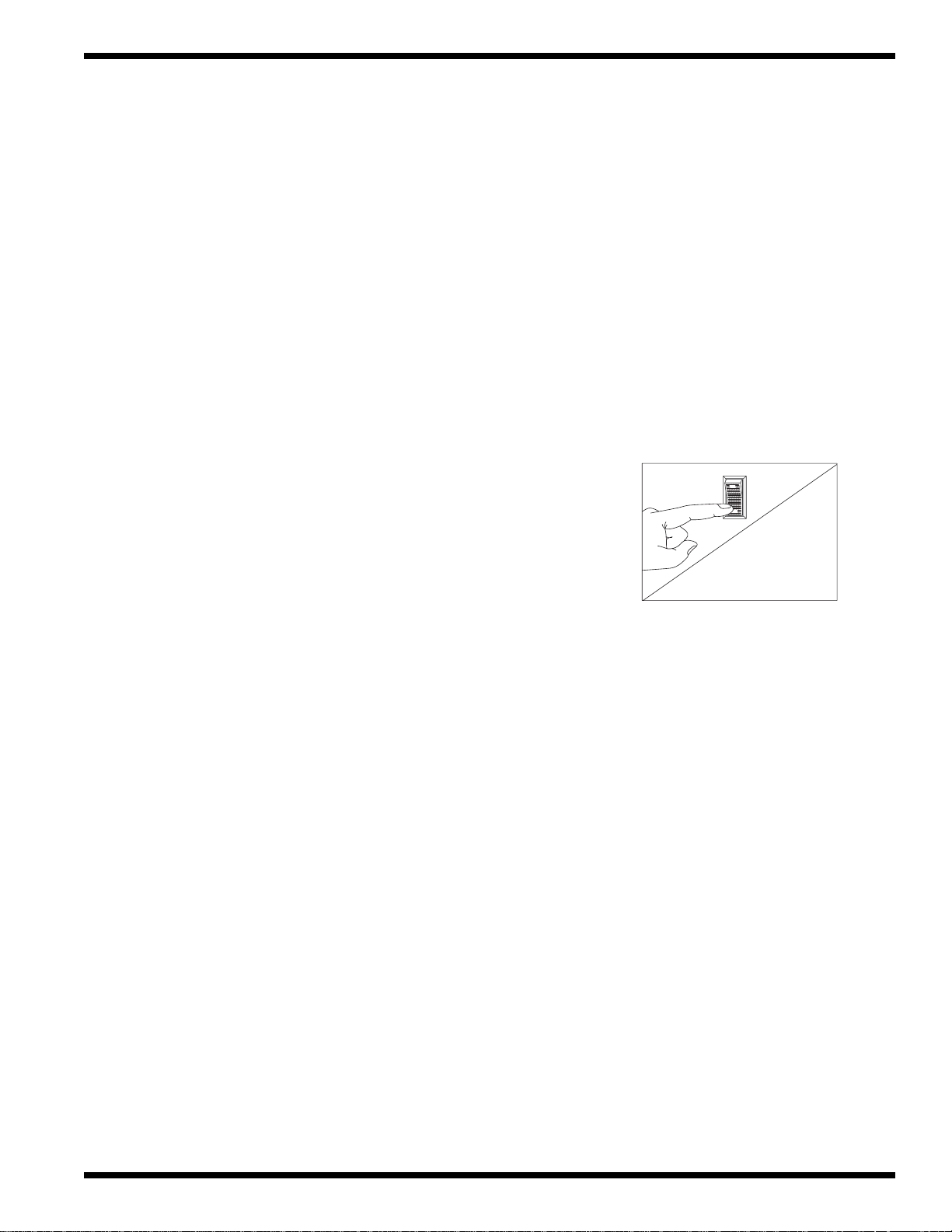
MACHINE VENT DAMPER SETTINGS
❑ Each vent stack is equipped with an adjustable damper.
❑ Proper adjustment of the dampers collects moist vapor as it
exits the machine. This prevents moisture from escaping into
the wash room.
CAUTION:
Opening the dampers too much will remove heat from the
machine interior and may make it difficult to maintain the
proper wash/rinse tank temperatures. Set the dampers to best
meet your particular installation. Figure A and B show the
minimum and maximum vent settings.
CHEMICAL CONNECTIONS
❑ Labeled connection points are provided inside the control cabinet
for chemical dispensing equipment.
These connection points include:
❑ A 120VAC detergent signal between Wire #10 and Common.
❑ A 120VAC rinse aid signal between Wire #12 and Common.
❑ Removable black plugs are located at various points on the
wash tank for the mounting of a conductivity cell.
❑ A removable plug on the final rinse piping is provided as a
rinse aid injection point.
9
INSTALLATION
MODEL UC-CW UC-CW-WS
LOAD END 400 CFM at 1/4" S.P. 300 CFM at 1/4" S.P.
UNLOAD END* 900 CFM at 1/4" S.P. 800 CFM at 1/4" S.P.
Figure 2
Control Cabinet
Chemical Connections
!
Minimum
Maximum
Damper
Handle
Fig. A
(Closed)
Damper
Handle
Fig. B
(Open)

INITIAL START UP
NOTE:
Perform the following checks and adjustments before placing the machine into service.
1. Check the interior of the machine and remove any foreign material.
2. Check the exterior of the machine — make sure that the conveyor belt is free of tape and
foreign material.
Baffles - Tank baffles redirect the flow of water from the spray arm systems back into the
tanks. This prevents water loss and keeps the wash, rinse, and final rinse water
in the proper tank.
3. Check the baffles — make sure that they are installed and positioned correctly.
4. Close the tank drain valves along the lower front of the machine.
5. Open the water supply valves. Check for leaks and take corrective action as required.
6. Open the steam supply valves (if applicable). Check for leaks and take corrective
action if required.
- Machine steam valves
- Blower Dryer (if applicable) steam valves
7. Turn the main power on at the breaker panel or fused disconnect switch.
- Machine main power
- Electric booster main power (if applicable)
8. Flip the Power Switch on the front of the Control Cabinet to the “ON” position.
- The Red power on light will illuminate.
- The machine will begin to fill with water.
9. Allow the machine to completely fill with water.
- The water will shut off automatically.
10. Check for leaks and take corrective action if required.
11. Monitor the tank thermometers for the proper temperature reading.
- Allow sufficient time for the tank heat to reach operating temperature.
- Refer to the chart below.
10
INITIAL START-UP
TANK Prewash Wash Power Rinse
TEMPERATURE
O
F 120O - 140
O
150O - 170
O
160O - 180
O
Figure 3 Baffles
LEFT TO RIGHT
MODEL
PRE-
WASH
BAFFLE BAFFLE BAFFLE
1 HP 3 HP 3 HP
RINSEWASH
FINAL
RINSE

12. Move the conveyor shut-off shelf located at the end of the unload section toward the machine.
- This resets the automatic conveyor stop system.
- When an object on the conveyor contacts the shut-off shelf, the conveyor stops.
13. Press the GREEN start button on the front of the control cabinet.
14. Check the direction of rotation of the conveyor belt by observing the direction arrow
decal on the large conveyor drive sprocket. The sprocket is located on the side of
the unload section.
15. If rotation direction is incorrect, reverse wires L1 and L2 on the disconnect switch side of
the main electrical connection terminal block located inside the control cabinet.
16. Adjust the conveyor belt drive clutch. The clutch is located on the large conveyor drive
sprocket on the side of the unload section. Refer to Fig. 4.
To adjust:
a. Tighten the clutch nut on the center of the drive sprocket until the
conveyor begins to move.
b. Have a person of average build (about 185 lbs.) hold the belt with
both hands and pull against the direction of travel.
c. Continue tightening the clutch nut until maximum effort against the
direction of travel is required to stop the belt.
NOTE:
Final adjustment of the clutch depends upon the overall length of the
conveyor belt and the maximum weight that may be placed on the
conveyor belt during normal operation.
CHECK AND ADJUST CLUTCH MONTHLY.
17. Check the alignment of the conveyor belt. Adjust the take-up
assemblies so that Conveyor Rollers (A) track evenly on Conveyor
Sprockets (B). See Fig. 5.
18. Check the Energy Sentinel (idle pump shut-off) by placing a tray
or dish on the moving conveyor belt.
- The pumps will start as the object enters the tunnel of the machine.
- The optional econorinse pump starts with the final rinse.
-
Check pump motor rotation, CW when viewed from the rear of motor.
19. Check the final rinse temperature as the object enters the
final rinse area.
- The Final rinse temperature must be 180-195°F.
- Adjust the temperature of the incoming water supply if necessary.
- Adjust the booster thermostat setting if necessary.
20. Check the Final rinse water pressure as the object enters the
final rinse area.
- The final rinse pressure must be 20-22 PSI.
- Adjust the Pressure Reducing Valve setting if necessary.
21. Check that the pumps and final rinse shut-off before the object reaches the
conveyor shut-off shelf.
22. Check that the conveyor belt stops when the object pushes the conveyor shut-off shelf.
23. Move the shut-off shelf toward the tunnel of the machine. The conveyor belt will start
moving again.
24. Push the RED stop button. The conveyor belt will stop moving.
25. Flip the power switch on the control cabinet to OFF. The red power light will go out.
26. Open all the drain valves and check that the house drains can handle the flow.
27. Remove any protective film from the stainless steel and install the side panels and chain guard.
11
INITIAL START-UP
Figure 4 - Conveyor
Belt Drive Clutch
Figure 5 - Conveyor
Belt Alignment
Clutch
Nut
A
B

OPERATION
Operation Steps
Perform the following steps to place your machine in operation. Refer to Fig. 6.
1. Check the curtains for correct placement in the machine.
- Be sure the short flaps of the Long Curtains face the load end of the machine.
2. Check the spray pipes.
- Be sure the spray pipe gasket is installed on the end of spray pipe before installing.
- Spray pipes are installed by inserting the pipe into the coupler and turning
1/4 turn clockwise.
3. Check the scrap screens.
- Install any scrap basket covers.
4. Check that the conveyor shut-off shelf is pushed toward the machine tunnel.
5. Close the drain valves, located under the base of each tank.
- When the drain handle is horizontal, the valve is open.
- When the valve handle is vertical, the valve is closed
6. Check the detergent and rinse aid supplies (supplied by others).
7. Turn on the detergent and rinse-aid dispensers (supplied by others).
8. Close all the doors making sure the door safety switches are activated.
9. Flip the Power Switch on the front of the control cabinet to “ON.”
- The RED power light will illuminate.
- The machine will automatically
fill with water.
- When the tanks are full, the
water will stop and the tank heat
will come on.
10. Fig. 7 illustrates the automatic fill
operation.
12
OPERATION
Figure 6
Curtain Placement
Figure 7 - Auto-Fill Operation
LONG CURTAIN
SHORT CURTAIN
SHORT CURTAIN
LONG CURTAIN
LEFT TO RIGHT
MODEL
PRE-
WASH
1 HP 3 HP 3 HP
RINSEWASH
FINAL
RINSE
LEFT TO RIGHT
MODEL
PRE-
WASH
1 HP 3 HP 3 HP
AUTO FILL 140° F
RINSEWASH
FINAL
RINSE
140° F

OPERATION (continued)
11. Wait for the tanks to reach operating temperature.
12. Monitor the temperature gauges located below the doors. Refer to the chart below for the
proper temperature readings.
13. Press the GREEN start button on the front of the control cabinet or the green start button
on the START/STOP station located at the load end of the machine.
- The conveyor belt will begin to move. (Pumps do not run at this time)
- If the conveyor belt does not move, recheck the position of the
conveyor shut-off shelf — and,
- Place the conveyor shut-off shelf in the operating position.
14. Scrap and flush the ware before loading it on the conveyor belt.
For the best washing results:
- Stagger objects across the conveyor belt.
- Cups, glasses, and silverware are best washed in racks. Distribute silverware evenly in
a single layer in the bottom of a flat rack.
As an object enters the tunnel of the load end, it will block the electric eyes. This starts the pumps.
- An Automatic timer controls the pump run time.
- The final rinse, also controlled by an automatic timer, will start as an object moves
near the final rinse area. The optional econorinse pump starts with the final rinse.
15. Check the final rinse temperature as the final rinse begins.
- The temperature gauge is located on the top of the machine in the final rinse piping.
- The correct reading must be between 180°-195°F.
16. Check the final rinse flow pressure during the final rinse.
- The pressure gauge is located on the lower panel of the unload section.
- The correct flow pressure must be between 20-22 PSI. The pressure gauge may read
more than 22 PSI before and after the final rinse cycle. This is a normal condition.
As an object exits the tunnel of the machine the automatic timers will:
- Shut off the final rinse and the pumps before the object reaches the conveyor shut-off shelf.
- If the conveyor belt is loaded with a number of objects, the final rinse and the pumps
will continue to run until an object pushes the conveyor shut-off shelf
into the OFF position.
- The conveyor belt and the final rinse will stop.
- The automatic timers will stop.
13
OPERATION
TANK Prewash Wash Power Rinse
TEMPERATURE
O
F 120O - 140
O
150O - 170
O
160O - 180
O
WARNING:
This machine contains moving conveyor parts
- Use caution when working near conveyor.
- Disconnect power to machine when cleaning or servicing.
!

OPERATION (continued)
17. Push the conveyor shut-off shelf towards the tunnel of the machine to return it to its
operating position. This will:
- Restart the conveyor belt and the final rinse.
- The automatic timers will restart where they left off. This ensures that any objects
remaining on the conveyor belt will be completely washed and sanitized by the
final rinse.
18. Press the RED stop button on the control cabinet or the START/STOP station
on the load section.
- The conveyor will stop.
- The final rinse will stop.
- The pumps will stop.
19. Press the GREEN start button on the control cabinet or the START/STOP station on the
load end. The conveyor, the final rinse, and the pumps will start again.
- The machine will continue to run until the automatic timers complete their timed
cycles or an object pushes the conveyor shut-off shelf to the “OFF” position.
Fresh make-up water is added to the tanks as required automatically.
- A majority of the fresh water comes from the Final Rinse.
- Additional make-up water is supplied by valves activated by float switches located
in each tank.
Refer to Fig. 8 below for the typical fresh water make-up supply.
14
OPERATION
Figure 8
Fresh Water Make-up
INDICATES WATER
LEVEL
LEFT TO RIGHT
MODEL
PRE-
WASH
RINSEWASH
FINAL
RINSE
OPTIONAL
1800 F
CROSS FLOW
PIPING
140° F
INPUT
COLD
WATER
MAINTENANCE
Regularly scheduled maintenance will increase the efficiency and life of your machine. A well
maintained machine gives better washing results and service. Undoubtedly, the time that you
invest in daily maintenance now, will pay-off in the future.
Cleaning your machine is the best maintenance that you can provide. Components that are not
regularly flushed and cleaned do not perform well.
The Maintenance Intervals shown in the following schedules are the minimum requirements
necessary for the proper performance of your machine. Shorten the maintenance intervals
whenever your machine is faced with abnormal working conditions, hard water, or
multiple shift operations.
Maintenance Schedule
CLEANING
• Every 2 Hours or After Each Meal Period
1. When the last object on the conveyor belt exits the tunnel of
the machine, the pumps will shut off automatically.
2. Press the RED stop button on the control cabinet or the
START/STOP station on the load section.
- The conveyor will stop.
3. Flip the Power switch on the front of the control cabinet to “OFF.”
- The Red power on light will go out.
4. Open the doors.
5. Open the drain valves and allow the machine to drain.
- The valve is open when the handle is placed in the horizontal position.
6. Remove the scrap screens and scrap baskets.
- Back flush the screens and baskets and reinstall in the machine.
- Check spray nozzles.
7. Close the drain valves and doors.
8. Flip the Power Switch on the front of the control cabinet to the “ON” position.
- The RED power light will illuminate.
- The machine will automatically refill with water.
• Every 8 Hours or at the End of the Day
1. Press the RED stop button on the control cabinet or the START/STOP station
on the load section.
2. Flip the Power Switch on the front of the control cabinet to the “OFF” position.
3. Remove all the scrap screens and baskets.
4. Back flush the scrap screens and baskets until clean.
DO NOT STRIKE SCREENS OR BASKETS AGAINST SOLID OBJECTS TO CLEAN.
5. Open the drain valves and allow the tanks to drain.
15
MAINTENANCE
POWER
ON
OFF

CLEANING (continued)
CAUTION:
Do Not Leave Water in the Tanks Overnight.
6. Flush the inside of the load and unload sections with clean water.
7. Flush the inside of the tanks with clean water and wipe away any residue.
8. Flush the pump suction strainers, the tank drain screens, and the drain screen
on the unload section.
9. Flush the inside of the machine again making sure all drains are clean and free flowing.
10. Remove the spray pipes by turning 1/4 turn counterclockwise.
- Remove the end cap from each spray pipe
- Flush the pipe and nozzles until clean.
Do not strike the spray pipes on solid objects to clean.
- Replace the end caps
- Make sure that the rubber gaskets are in place on the end of the spray pipe.
11. Reinstall the spray pipes by turning 1/4 turn clockwise.
12. Clean the final rinse pipe nozzles of any mineral deposits.
(A straightened paper clip works very well as a cleaning tool).
13. Remove and clean the curtains. Allow the curtains to air dry.
14. Reassemble the machine.
15. Leave the doors open to allow the interior of the machine to air dry.
16. Clean the exterior of the machine. DO NOT HOSE DOWN WITH WATER.
17. Report any unusual conditions to your supervisor.
Lubrication
• Every 3 months
1. Check the oil level in the conveyor drive gear reducer. Refill with SAE 90 gearcase oil.
2. Add grease to the conveyor shaft bearings; usually one pump from a grease gun using a
general purpose grease.
3. Motor bearings do not require lubrication.
4. Apply a thin coat of grease to the conveyor drive sprocket chain. Avoid getting grease on
the drive clutch; wipe any excess grease off immediately.
Operation Checks
• Daily
1. Check temperature gauges for proper readings.
2. Check pressure gauge for proper reading.
3. Check pumps for leaks around motor shaft.
4. Inspect general condition of machine.
5. Check chemical supplies (supplied by others) and refill as necessary.
16
MAINTENANCE
!

Operation Checks
• Weekly
1. Inspect all water lines for leaks and tighten at joints if required.
2. Clean all detergent residue from the exterior of the machine.
3. Check the drains for leaks.
4. Clean accumulated mineral deposits from the tank heating elements
or steam coils.
5. Remove and inspect each spray pipe for blockage and clean if required.
6. Clean the final rinse nozzles of accumulated mineral deposits.
7. Check the float switches located in each tank to ensure they move freely.
8. Inspect the conveyor belt for broken or worn parts.
9. Inspect the electric eyes and clean the lenses.
10. Inspect the conveyor shut-off shelf for freedom of travel.
11. Check the conveyor drive clutch adjustment.
Deliming
Mineral deposits, which are frequently referred to as lime because of their white color,
accumulate in the interior of the machine over time. The amount of lime build-up depends on
the mineral content of your water supply. Machines in regions of the country that have hard
water (high mineral content) will require more frequent deliming than in regions
with soft water (low mineral content).
NOTE:
Consult your chemical supplier for an appropriate deliming solution.
• Weekly or as required
1. Inspect the interior of the machine for lime deposits.
2. Follow the chemical supplier’s recommendations for the deliming solution.
3. Thoroughly flush the interior of the machine when the deliming is complete.
17
MAINTENANCE
WARNING:
Deliming solutions or other acids must not come in contact with
household bleach (sodium hypochlorite) or any chemicals containing
chlorine, iodine, bromine, or fluorine. Mixing will cause hazardous gases
to form. Skin contact with deliming solutions can cause severe irritation
and possible chemical burns. Consult your chemical supplier for specific
safety precautions.
!

TROUBLESHOOTING
On occasion your machine may not operate as expected.
Use the checklist below before you decide that a mechanical or electrical failure has occurred.
Checklist
1. Are the main disconnect switches, breakers, or motor overloads turned ON?
2. Are the main water and steam supplies turned ON?
3. Are the drain valves closed?
4. Are the spray pipes and rinse nozzles clean?
5. Are the spray pipes in the proper locations?
6. Are the pump intakes clean?
7. Are the scrap screens clean and in place?
8. Are the thermostats correctly adjusted?
9. Are the high limit temperature thermostats reset?
10. Are the doors fully closed?
11. Are the conveyor shut-off and drive assemblies in operating condition?
12. Are the chemical supplies adequately filled?
If a problem still exists after verifying the checklist, refer to the following
Troubleshooting Chart.
CONDITION CAUSE SOLUTION
Conveyor will not run Door not closed................................... Make sure doors are fully closed
Door safety switch faulty.................... Contact your service agency
Start switch faulty ............................... Contact your service agency
Main switch OFF ................................ Check disconnect
Control panel power switch OFF........ Flip switch ON
Conveyor shut-off shelf operated........ Move shelf toward tunnel of machine
Motor overload protector tripped........ Reset overload in control cabinet
Green start button not pressed ............ Press green start button
Conveyor runs but Nothing on the conveyor..................... Load the conveyor
Prewash, Wash, and Electric eyes (Idle pump shut-off) Clean the electric eye lenses
Power Rinse pump system faulty ....................................... Flip the Automatic/Manual switch in the
will not run control cabinet to MANUAL and
Contact your service agency
Optional EconoRinse Final Rinse Timer not calling Refer to EconoRinse section operation
pump will not run for operation........................................ Appendix A (Page 104)
Motor overload tripped ....................... Reset overload in control cabinet
Defective motor................................... Contact your service agency
18
TROUBLESHOOTING

TROUBLESHOOTING
CONDITION CAUSE SOLUTION
A single pump will not run Motor overload tripped....................... Reset overload in control cabinet
Defective motor................................... Contact your service agency
Low or no water Main water supply is turned off .......... Turn on house water supply
Drain valves are open.......................... Close all drain valves
Doors are not fully closed ................... Close doors
Faulty fill valve................................... Contact your service agency
Stuck or defective float switch............ Free float /Contact service agency
Cross-flow piping misadjusted/
clogged................................................ Adjust cross-flow setting/Clean piping
Clogged strainer at supply
connection ........................................... Clean strainer screen
PRV misadjusted or defective............. Readjust pressure setting or replace PRV
Continuous water filling Stuck or defective float switch............ Free float/Contact service agency
Fill valve will not close....................... Clean valve,repair or replace valve
Drain valves open................................ Close drain valves
Wash/Power Rinse tank temperature Incoming water temperature at machine Raise incoming temperature
is low when machine is operating is too low ............................................. 140°F minimum for 40° rise booster
110°F minimum for 70° rise booster
180° F minimum without booster
Defective thermometer........................ Check or replace
Defective thermostat ........................... Readjust setting or replace
Defective electric heater element........ Check or replace
Low steam pressure or volume........... Check steam supply pressure
Defective steam trap............................ Check or replace
Defective solenoid valve ..................... Check or replace
Prewash tank temperature Incoming cold water temperature Lower incoming water temperature
is too high (Optional Cold too high................................................ to maximum of 65°F
Water thermostat Only) Defective cold water thermostat ......... Check or replace
Insufficient pumped spray Clogged pump intake screen............... Clean
pressure Clogged spray pipe.............................. Clean
Scrap screen full.................................. Must be kept clean and in place
Low water level in tank ...................... Check drain valves
Pump motor rotation incorrect............ Reverse wires L1 and L2 in control cabinet
Defective pump seal............................ Contact service agency
Insufficient final rinse or Faulty pressure reducing valve
no final rinse (PRV).................................................. Clean or replace
Improper setting on PRV.................... Set Flow pressure to 20-22 PSI
Clogged rinse nozzle or pipe .............. Clean
Improper water line size...................... Installer must change to proper size
Clogged “Y” strainer........................... Clean or replace
19
TROUBLESHOOTING

TROUBLESHOOTING
CONDITION CAUSE SOLUTION
Low final rinse temperature Low incoming water temperature ....... Raise incoming water temperature
140°F for 40° rise booster
110°F for 70° rise booster
180°F without booster
Defective thermometer........................ Check or replace
Defective thermostat ........................... Recalibrate or replace
High limit thermostat tripped.............. Reset or replace
Low steam pressure............................. Check steam supply pressure
Poor washing results Detergent dispenser not operating ...... Contact the chemical supplier
Detergent supplied not strong
enough................................................. Contact the chemical supplier
Wash water temperature too low See Condition “Wash/Rinse tank
............................................................. water temperature too low”
Spray pipes clogged............................ Clean
Improperly scrapped dishes ................ Check scrapping procedures
Ware improperly loaded on
conveyor.............................................. Stagger ware on belt
Maintenance not performed
as required........................................... See Maintenance Schedule
Electric elements/steam coils have ..... Clean and delime
lime build-up....................................... Contact the chemical supplier
Poor drying results Excessive humidity in
warewashing area................................ Check vent dampers and exhaust fans
Improperly stacked dishes
after washing....................................... Check unloading procedures
Insufficient rinse-aid ........................... Contact chemical supplier
Final rinse temperature See Condition “Final Rinse temperature
too low ................................................ too low”
20
TROUBLESHOOTING

BASIC SERVICE
To the Reader—
This section is intended for qualified service and maintenance personnel only.
DO NOT ATTEMPT ADJUSTMENTS OR REPAIRS IF YOU ARE NOT QUALIFIED.
A qualified servicer is someone who has:
1. A thorough knowledge of all safety precautions and procedures.
2. A thorough knowledge of basic electricity and electrical troubleshooting methods.
3. A thorough knowledge of dishwashing machine mechanics and operation.
To the Qualified Servicer—
The following service information explains procedures for adjusting and repairing some of the
major components on the UC-CW dishwashers. In addition, you will find some basic guidelines
for troubleshooting and evaluating problems.
Champion dishwashers contain some unique design features that may be unfamiliar to you. We
have included explanations about a number of these features.
This Basic Service section does not cover all possible repair procedures. However, if you require
additional service support, you can call:
Champion National Service
1-800-858-4477
Please have the Model and Serial Number of the machine ready when you call.
21
BASIC SERVICE
WARNING:
Serious personal injury may result
if persons lacking the proper training or experience attempt to adjust or
repair a Champion Dishwashing Machine.
—In addition—
Serious or permanent damage to the machine may result
if persons lacking the proper training or experience attempt to adjust or
repair a Champion Dishwashing Machine.
!
WARNING:
This machine contains moving conveyor parts
- Use caution when working near conveyor.
- Disconnect power to machine when cleaning or servicing.
!

Note:
Champion offers a variety of options for the Upright Conveyor dishwasher.
It is extremely important that you identify the options installed on the machine BEFORE you
begin repairs.
The basic operation of the upright conveyor is the same for all models. If you are not completely
familiar with the design and operation of your machine, please read all the information
contained in this manual before attempting any repairs. What appears to be a serious problem at
first, may be corrected with a simple maintenance or operation check.
ELECTRICAL SERVICE
Power Requirements: All models require 3 Phase power.
Standard voltages are available in 208/60/3 240/60/3 460/60/3
Non-standard voltages are available—Consult the factory.
Service Connections: The main power connection is made at a single point in the Control
Cabinet. Optional Electric Boosters have a separate service connection.
Optional Electric Blower dryers have a separate service connection.
Line Voltage: Three phase line voltage
is supplied to: Pump motors
Drive Motor
Optional Blower Dryer motor
Electric tank heater elements
Optional Booster tank heater elements
Single phase line voltage
is supplied to: Control Transformer — (In control cabinet)
[Step-down Line Voltage: 120VAC]
Control Voltage: 120VAC is supplied by
the secondary of the
control transformer to: Control cabinet switches
Remote pushbutton stations
The Electric Eye circuit input
Pump & Final Rinse Timers
Solenoid Valves
Thermostats
Contactors
Motor starter overloads
Hold-in Relay
24VAC Control Transformer
[Step-down 120VAC:24VAC]
22
ELECTRICAL SERVICE