

Page 1

Steuerungsset
CB400
für
AC SCHIEBETORANTRIEBE
-Einbauanleitung-
www.liftmaster.de
Email: info@chamberlain.de
Chamberlain GmbH
Alfred Nobel Strasse 4
D-66793 Saarwellingen
Germany
Page 2
Achtung:
Dieses Produkt darf nur durch eine Elektrofachkraft installiert werden.
Nur entsprechend geschulte Elektrofachkräfte dürfen die Steuerung anschliessen, programmieren und
warten.
Elektrofachkräfte erfüllen die folgenden Anforderungen:
- Kenntnis allgemeiner und spezieller Sicherheitsvorschriften sowie Unfallverhütungsmaßnahmen,
- Kenntnis entsprechender elektrotechnischer Vorschriften,
- sie sind geschult in Umgang und Wartung entsprechender Sicherheitsausrüstung,
- sie sind in der Lage Gefahren zu erkennen, die durch Elektrizität entstehen können.
Aufgabenbereich dieser Anleitung:
Diese Anleitung beschreibt den Einbau und die Anwendungsmöglichkeiten des Produktes CB400
(Steuerung AS210B): Einige Eigenschaften benötigen das optionale ZM-SKS-B Zusatzmodul.
Diese Anleitung darf nur mit den Antrieben SLY2500 und SLY3500 verwendet werden.
Für die mechanische Installation benutzen Sie bitte die dem Antrieb beliegende Anleitung.
Page 3

Eigenschaften
Antriebstyp SLY2500 SLY3500
Motorspannung 230V ~ 400V ~
Steuerung (CB400 kit) AS210B AS210B
Max. Torgewicht (kg) 2500kg 3500kg
Motorschutzschalter nein ja
Thermoschutz (Motor) ja nein
Totmann-Funktion ja ja
Automatik-Funktion ja* ja*
Lichtschranke ja ja
Funk extern extern
Automatisch Schliessen ja* ja*
Blinklampe ja* ja*
Kontaktleisten ja* ja*
Notstopp ja* ja*
Ampel-Funktion mit Rotlicht ja* ja*
WICHTIG:
Stellen Sie vor dem Einbau der Steuerung sicher ob ihre Steuerung an 400Volt/
3 Phasen oder
an 230Volt/ 1 Phase (X4 Anschluss) angeschlossen werden muss.
* benötigt ZM-SKS-B Zusatzmodul
A. Einstelltaster AUF Richtung (S01) /
A. Einstelltaster ZU Richtung (S02)
X1: Netzanschluss
X2: Motor Anschluss / Sicherheitsstromkreis
X3: Anschluss Bedienelemente
X4: Anschluss für wahlweise 230V / 400V
X5: Anschluss Endschalter
X6: Anschluss für Dreifachtaster
X7: Stecksockel für ZM-SKS-B Zusatzmodul
X8: Stecksockel für Spiralkabel
X9: Anschluss für Ampel-Funktion / Hoflicht
(nur bei Gebrauch des ZM-SKS-B Zusatz-
moduls)
X10: Steckbrücken für Selbsthaltung ZU - AUF
X11: Ohne Funktion
Page 4
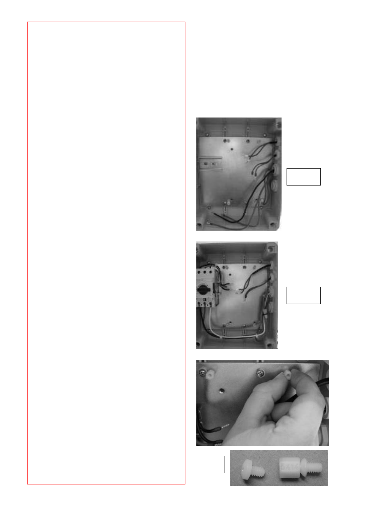
Einbau der Steuerung:
Die Einbauanleitung setzt voraus, dass keine
Steuerung vorinstalliert ist.
Generelle Schritte:
1. Haube des Antriebs entfernen
2. Abdeckung der Steuerungsbox entfernen
3. Vergleich generelle Vorverkabelung
der Steuerung
• Pic. 1: 230Volt 1-Phasen Motor
Verkabelung
• Pic. 2: 400Volt 3-Phasen Motor mit
bereits installiertem
Motorschutzschalter
4. Einbau der Halterungen für die
Steuerung
• 4 Stück in die markierten Löcher
• Siehe Pic. 3
Pic. 3
Pic. 1
Pic. 2
Page 5
Anschlussdiagramm für
Netzanschluss und Motor mit
400Volt, 3-Phasen
F1 Thermosicherung, Steuerspannung
F2 Thermoschutz Motor
K1 Schütz AUF
K2 Schütz ZU
M Motor (400V / 50Hz / 3-Phasen)
S3 Sicherheitsendschalter AUF
(NC Kontakt)
S4 Sicherheitsendschalter ZU (NC contact)
S7 Sicherheitsschalter, Nothandbetrieb
(NC Kontakt)
T1 Transformator
X1 Anschlussblock für Netzanschluss
X2 Anschlussblock für Motor
X4 Anschlussblock für wahlweise:
1+2 = 230Volt
2+3 = 400Volt
Nicht gezeigt:
Netzanschluss:
• L1 = L
• L2 = L
• L3 = L
• PE = PE
ACHTUNG:
Bei Anschluss X4 muss auf den Klemmen
2+3 eine Steckbrücke (Jumper)
aufgesteckt sein (Pic. 1).
Pic. 1
Page 6
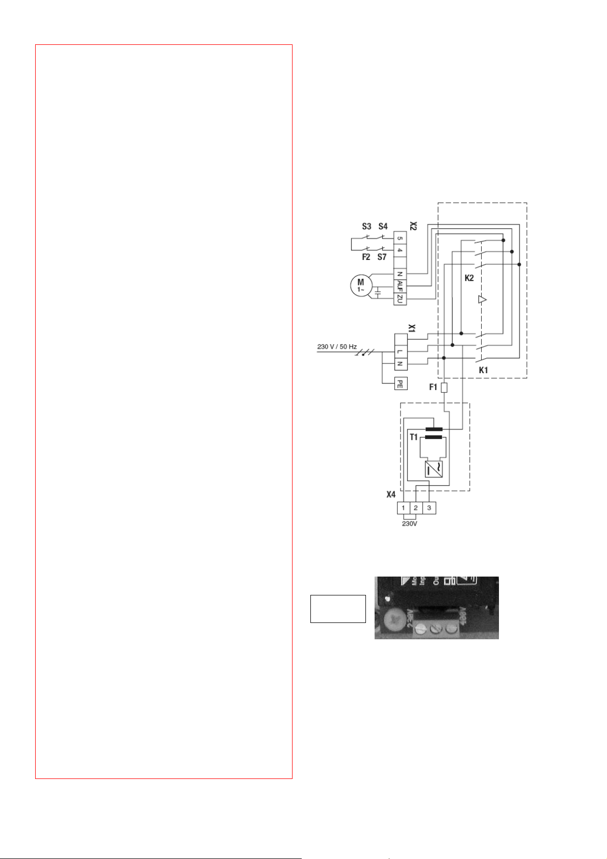
Anschlussdiagramm für
Netzanschluss und Motor mit
230Volt, 1-Phase
F1 Thermosicherung, Steuerspannung
F2 Thermoschutz Motor
K1 Schütz AUF
K2 Schütz ZU
M Motor (230 V / 50 Hz)
S3 Sicherheitsendschalter AUF
(NC Kontakt)
S4 Sicherheitsendschalter ZU
(NC Kontakt)
S7 Sicherheitsschalter, Nothandbetrieb
(NC Kontakt)
T1 Transformator
X1 Anschlussblock für Netzanschluss
X2 Anschlussblock für Motor
X4 Anschlussblock für wahlweise:
1+2 = 230Volt
2+3 = 400Volt
Netzanschluss (siehe Detailschaltplan):
ACHTUNG:
Bei Anschluss X4 muss auf den Klemmen
1+2 eine Steckbrücke (Jumper)
aufgesteckt sein (Pic. 1).
Pic. 1
Page 7
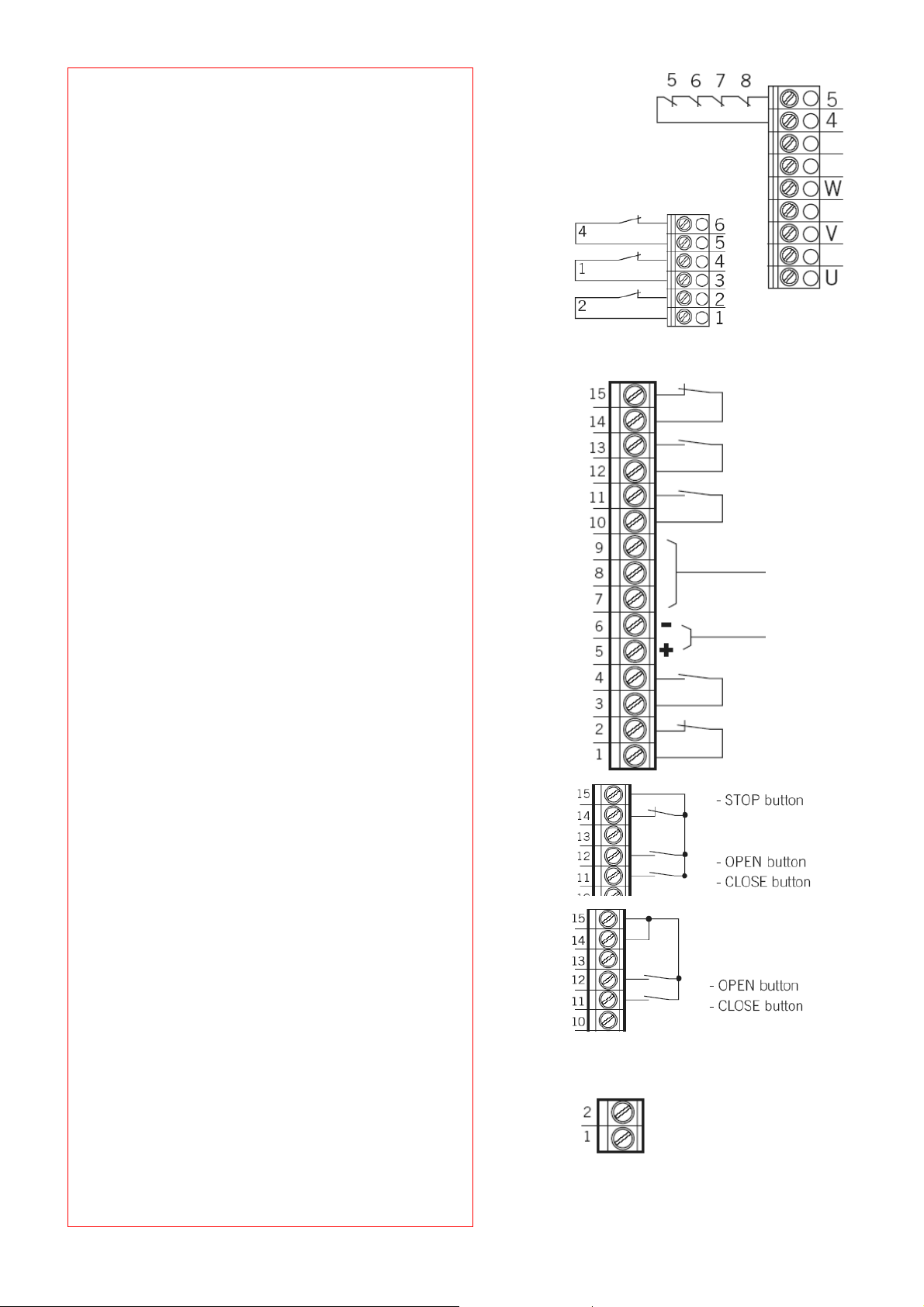
Standard Anschlüsse:
Anschlüsse X5 und X2
Endschalter
1. Endschalter AUF
2. Endschalter ZU
3. Vorendschlter AUF
4. Vorendschalter ZU
(nach Aktivierung reversiert das Tor nicht)
5. Überhitzungsschutz für Motor
6. Notbetrieb (NC Kontakt)
7. Sicherheitsendschalter ZU
8. Sicherheitsendschalter AUF
Anschluss X3
Sicherheitseinrichtungen und
Bedienelemente
14 + 15 STOP Eingang
12 + 13 Eingang AUF Richtung
10 + 11 Eingang ZU Richtung
7, 8 + 9 Kontaktleiste ZU Richtung
(ZM-SKS-B Zusatzmodul notwendig)
5 + 6 Ausgang 24Volt DC , max . 150mA
5= +
6= 3 + 4 Eingang Funk (Automatikbetrieb)
(ZM-SKS-B Zusatzmodul notwendig)
1 + 2 Eingang Lichtschranke
(ZM-SKS-B Zusatzmodul notwendig)
BEISPIEL:
AUF/ STOPP / ZU (4 adrige Variante)
BEISPIEL:
AUF / ZU
X5
X3
X2
Anschluss X9
1 + 2 Potenzialfreier Kontakt für Ampelfunktion
mit Rotlicht oder andere Beleuchtungsarten
X9
Page 8

EXTERNE
SICHERHEITSEINRICHTUNGEN
Verkabelungsbeispiele:
(ZM-SKS-B Zusatzmodul notwendig)
1. Für optoelektrische Kontaktleisten:
ZU Richtung
Einstellungen: Dipschalter 1 = AUS
Klemme 9: +12Volt
Klemme 8: Signal
Klemme 7: Erde
2. Für 8,2kOhm Kontaktleisten
ZU Richtung
Einstellungen: Dipschalter 1 = AN
Klemmen 7+ 8
3. Für pneumatische Kontaktleisten
ZU Richtung
Einstellngen: Dipschalter 1 = AN
Dipschalter 2 = AN
8.2kOhm Widerstand angeklemmt
an Klemmen 7+8
4. Für Relais-Lichtschranken mit
3-Kabel System
ZU Richtung
Klemme 5: +24Volt
Klemme 6: Erde
Klemme 2: Signal
Hinweis: Eine 4-adrige Lichtschranke
muss gebrückt werden.
5. Für Relais-Lichtschranken mit
4-Kabel System
AUF Richtung
Anschluss 14+15:
Klemme 5 : + 24VDC
Klemme 6 : - 24VDC
Weitere Optionen:
• Für Chamberlain 2-kabel Lichtschranken ist
die Interface Box 600213-2 (optional
erhältlich) erforderlich. Drei weitere
Lichtschranken oder Kontaktleisten können
angeschlossen und unabhängig überwacht
werden, Typ 8,2kOhm Kontaktleisten oder
auch gemischt mit 2-Kabel Lichtschranken.
Die Interface Box kann an jeden beliebigen
Anschluss und an den Ausgang für
Sicherheitseinrichtungen angeklemmt
werden, der die AUF oder ZU Richtung
überwacht. Die Box hat den Schutzgrad
IP55 und kann somit auch im Freien
installiert werden.
Page 9

Weitere Einstellungen
Anschluss X6
Anschluss für externen Dreifachtaster.
Wenn der Anschluss nicht belegt ist, muss die
Steckbrücke J4 wie gezeigt aufgesteckt sein.
Anschluss X8
Anschluss für Spiralkabel
Wenn der Anschluss nicht belegt ist, muss die
Steckbrücke J3 wie gezeigt aufgesteckt sein.
Anschluss X7
Anschluss für das ZM-SKS-B Zusatzmodul
Wenn der Anschluss nicht belegt ist, muss die
Steckbrücke J5 wie gezeigt aufgesteckt sein.
Anschluss X10
Steckbrücken für Selbsthaltung
AUF Richtung: J1
ZU Richtung: J2
• J1 und J2 Steckbrücke abziehen wenn das
ZM-SKS-B Zusatzmodul verwendet wird.
• J1 und J2 Steckbrücke aufgesteckt lassen,
wenn das ZM-SKS-B Zusatzmodul nicht
verwendet wird.
WARNUNG:
Ist J2 aufgesteckt, erfolgt kein Stoppbefehl
der Kontaktleiste in ZU Richtung
Anschluss X11
Ohne Funktion
Page 10

Abmessungen: 167 x 85 x 190
Stromversorgung über:
L1, L2, L3, PE:
Sicherung: TYP 10A K
Verbrauch nur Steuerung: Max. 100 mA
Spannung Steuerung: 24 V
Eingänge Steuerung: 24V
Ausgänge Steuerung: 24 V
Sicherheitsstromkreis /
Notbetrieb aus:
Eingang Sicherheitskontaktleiste:*
230V oder 400V
50/60 Hz
max. Leistung 2200 W
3.2 A
ED 60%
DC, max. 250 mA
Potenzialfreier NO Kontakt;
min. 10 mA ; max. 230V
AC / 4A. abgesichert durch
eine selbstzurücksetzende
Sicherung für externe
Messfühler; alle
Spannungseingänge der
Steuerung sind galvanisch
vom Netz getrennt.
DC, alle Eingänge
müssen potenzialfrei sein;
minimale Signaldauer für
Steuerungsbefehl >100
ms
DC, max. 150 mA
Alle Eingänge müssen
potenzialfrei sein; wenn
der Sicherheitsstromkreis
unterbrochen ist, ist keine
weitere elektronisch
gesteuerte Bewegung des
Antriebs möglich, auch
nicht in der Totmann
Einstellung.
für 8.2KΩ elektronische
Sicherheitskontaktleisten,
Lastwiderstand und für
generatorische optische
Systeme
Ausgänge Relais:* Wenn induktive Lasten
Temperaturbereich: In Betrieb: -10°C ...
Luftfeuchte: bis zu 80% unkondensiert
Gewicht: ca. 1.8 kg
Vorgaben: Standards
Die Torsteuerung für SLY2500 and 3500……… AS210B erfüllt die Anforderungen der geltenden
Abschnitte der Normenvorschriften:
EN55014 • EN61000-3 • EN60555, EN60335-1 • ETS300 683 • EN60335-1: 2002 • EN60335-2-103:
2003 • EN55014-1: 2000 + A1 + A2 • EN55014-2: 2001 • EN61000-3-2: 2000 • EN61000-3-3: 1995 +
A1 • EN 301 489-3, V1.3.1 • EN13241-1
sowie die Bestimmungen und sämtliche Ergänzungen
der EU-Vorschriften ..............................................2006/95/EC, 2004/108/EC, 1999/5/EG
Die automatischen Torantriebe, erfüllen die Bestimmungen der EU-Vorschrift 98/38/EC
und ihre Ergänzungen, wenn sie gemäß den Anleitungen des Herstellers installiert und
gewartet werden und wenn sie mit einem Tor verwendet werden, das ebenfalls gemäß
Herstelleranleitungen installiert wurde und gewartet wird.
Harry Naumann
Manager, Regulatory Affairs
Chamberlain GmbH
D-66793 Saarwellingen
July, 2008
Konformitätserklärung
Einschlußerklärung
Die Unterzeichnende erklärt hiermit, dass das vorstehend
angegebenne Gerät sowie sämtliches im Handbuch aufgeführtes
Zubehör den oben genannten Vorschriften und Normen entspricht.
anliegen (z.B. zusätzliche
Relais oder Bremsen)
müssen diese erst mit
entsprechenden Entstörungsfiltern (Freilaufdioden,
Varistoren,Widerständen,
Kondensatoren
ausgestattet sein.
Einmal unter Leistung
benutzte Kontakte können
keine Kleinströme mehr
schalten.
+45°C
Außer Betrieb: -25°C ...
+70°C
Page 11

February 27, 2008
Page 12

CONTROL BOARD KIT
CB400
for
AC SLIDING GATE OPERATORS
-Installation Instructions-
www.liftmaster.de
Email: info@chamberlain.de
Chamberlain GmbH
Alfred Nobel Strasse 4
D-66793 Saarwellingen
Germany
Page 13

Attention:
This product may only be installed from professional installers. Only qualified and trained electricians
may connect, programme and service the controls. Qualified and trained electricians meet the
following requirements:
- have knowledge of the general and specific safety and accident prevention regulations,
- have knowledge of the relevant electrical regulations,
- are trained in the use and care of appropriate safety equipment,
- are capable of recognising the dangers associated with electricity.
Scope of these instructions:
These instructions describe the installation and options for the product CB400 (control board
AS210B): Some features require the optional ZM-SKS plug in logic board to work. This manual should
only be used together with SLY2500 and SLY3500 operators!
For mechanical installation of the operator use the instruct ion included with the operator.
Page 14

FEATURES
Type of gate motor used SLY2500 SLY3500
Motor Voltage 230Volt 400Volt
Controller (CB400 kit) AS210B AS210B
Max. Gate weight (kg) 2500kg 3500kg
Motor Protection Switch no yes
Thermal protection (internal) yes no
Hold to run function yes yes
Automatic function yes yes
IR-Sensor yes yes
Radio external external
Automatic close yes* yes*
Flashing Light yes* yes*
Safety edges yes* yes*
Emergency Stop yes* yes*
External Light switching function yes* yes*
Traffic light with Red-Light yes* yes*
IMPORTANT:
BEFORE the installation of control board make sure it is checked if your control motor
requires to be set for 400Volt, 3-Phase or
* requires ZM-SKS-B plug in card
230Volt, 1-Phase (X4 terminal).
A. Test button OPEN direction (S01) /
A. Test button CLOSE direction (S02)
X1: Terminals Mains
X2: Terminals Motor / safety circuit of drive
X3: Terminals Command devices
X4: Terminals Selection 230V / 400V
X5: Terminals Limit switches
X6: Terminals for 3-way switch
X7: Plug-in socket for ZM-SKS-B circuit card
X8: Plug-in socket for spiral cable
X9: Terminals for traffic light / yard light
(only in connection with a ZM SKS B plug-
in circuit card)
X10: Terminals for press-and-release
CLOSE- OPEN
X11: Not used
Page 15

Installation of control board:
The assembly instructions assume that there
is no control board pre-installed.
General steps:
1. Remove cover of operator
2. Remove control board box cover
3. Compare general pre-assembly of
control board
• Picture 1: 230Volt 1-Phase motor
assembly
• Picture 2: 400Volt 3-Phase motor
with motor protection switch
installed
4. Install the control board holders
• 4 pieces into the marked holes
• See picture 3
Pic. 3
Pic. 1
Pic. 2
Page 16

Circuit diagram for mains
connection and motor
400 V / 3-phase
F1 Thermal fuse, control voltage
F2 Thermal overload protection for motor
K1 Protection OPEN
K2 Protection CLOSE
M Motor (400 V / 50 Hz / 3-phase)
S3 Safety limit switch OPEN (NC contact)
S4 Safety limit switch CLOSE (NC contact)
S7 Safety switch, emergency manual
operation
(NC contact)
T1 Transformer
X1 Terminal block for mains connection
X2 Terminal block for motor
X4 Terminal block for mains voltage
selection
1+2 = 230Volt
2+3 = 400Volt
Picture of general wiring 400Volt shows:
• Connection to motor via motor
protection switch
• Limit switch connected (right side)
• Ground wire connected to board
Not shown:
Connect mains to:
• L1 = L
• L2.= L
• L3 = L
• PE = PE
ATTENTION:
Terminal X4 must have a jumper between
terminals 2+3 installed! (Picture 1)
Pic. 1
Page 17

Circuit diagram for mains
connection and motor
230V / 1-phase
F1 Thermal fuse, control voltage
F2 Thermal overload protection for motor
K1 Protection OPEN
K2 Protection CLOSEM Motor (230 V / 50
Hz)
S3 Safety limit switch OPEN (normally
closed contact)
S4 Safety limit swit ch CLOSE (normally
closed contact)
S7 Safety switch, emergency manual
operation (normally closed contact)
T1 Transformer
X1 Terminal block for mains connection
X2 Terminal block for motor
X4 Terminal block for mains voltage
selection
Picture of general wiring 1-Phase 230Volt
motor
• Connection to motor via motor
protection switch
• Limit switch connected (right side)
• Ground wire connected to board
Not shown:
Connect mains to:
L2 = L- 230Volt
L1 = N Neutral
PE = PE
ATTENTION:
Terminal X4 must have a jumper
between terminals 1+2 installed!
(Picture 1)
Pic. 1
Page 18

GENERAL CONNECTIONS:
Terminals X5 and X2
Limit switches
1. Limit switch OPEN
2. Limit switch CLOSE
xx??
3.
4. Pre-limit switch CLOSE (after activation th e
door does not reverse)
5. Thermal overload protection for motor
6. Emergency operation (normally closed
contact)
7. Safety limit switch CLOSE
8. Safety limit switch OPEN
Terminal block X3
Safety Devices and Commands
14 + 15 STOP Input
12 + 13 OPEN Direction Input
10 + 11 CLOSE Direction Input
7, 8 + 9 Safety Edges Closed Direction.
Requires the ZM-SKS module
5 + 6 Output 24Volt DC , max . 150mA
5= +
6= -3 + 4 Radio input (Automatic operation)
Requires the ZM-SKS module
1 + 2 Photocell Close connection
Requires the ZM-SKS module
EXAMPLE:
OPEN/ STOP CLOSE (4 lead solution)
EXAMPLE:
OPEN / CLOSE
X5
X3
X2
Terminal block X9
1 + 2 Dry Contact for red light traffic light
or other lights
X9
Page 19

EXTERNAL SAFETY- DEVICES
Connection (wiring) examples:
Requires optional ZM-SKS-B module to be
installed
1. For optoelectric safety edges:
Closing direction
Settings: Dipsw itch 1 = OFF
Terminal 9: +12Volt
Terminal 8: Signal
Terminal 7: Ground
2. For 8.2KOhm safety edges
Closing direction
Settings: Dipsw itch 1 = ON
Terminal 7+ 8
3. For pneumatic safety edges
Closing direction
Settings: Dipsw itch 1 = ON
Dipswitch 2 = ON
8.2KOhm resistor in place
Terminal 7+8
4. For relay photocell with 3-wire
technology
Closing direction
Terminal 5: +24Volt
Terminal 6: Ground
Terminal 2: Signal
Notice: A 4-wire photocell requires a
jumper to be added
5. For relay photocell with 4-wire
technology
OPENING direction
Terminal 14+15: Signal
Terminal 5 : + 24VDC
Terminal 6 : - 24VDC
MORE OPTIONS:
• For Chamberlain 2-wire photocells the
optional 600213-2 interface box is
required. Three more photocells or safety
edges may be connected and monitored
independently, Type suitable 8.2KOhm
type or mixed with 2-wire Chamberlain
photocells. The interface box can be
connected to any terminal and connected
to the safety output protecting the opening
OR the closing direction. The box is IP55
and can be located outside.
Page 20

OTHER SETTINGS
X6 Socket
Socket for an external 3-way switch.
If the terminal is not used by a connector plug
the stop jumper marked on J4 must be
inserted.
X8 Socket
Socket for coiled (spiral) cable.
If the terminal is not used by a connector plug
the jumper marked on J3 must be inserted.
X7 Socket
Socket for the ZM-SKS plug in board.
If the terminal is not used by the module the
jumper marked J5 must be inserted.
X10 Socket
Terminal for press and release full open
and full close.
Opening direction: J1
Closing direction: J2
• J1 and J2 jumper OPEN if ZM-SKS board is
used.
• J1 and J2 jumper CLOSED if not
connected.
WARNING:
If jumper J2 is inserted the safety edge output
does NOT revers and stop the closing
direction!
X11 Socket
No Function
Page 21

Dimensions of circuit
167 x 85 x 190
board:
Power supply via L1, L2,
L3, PE:
230 V or 400 V, 50 / 60
Hz; - max. power input
2200 W - 3.2 A; duty cycle
60% for a maximum
running time of 120 s
Fuse protection: 10A K type
Consumption of the
max. 100 mA
controls alone:
Control voltage: 24 V
DC, max. 250 mA;
protected by self-resetting
fuse for external sensor
systems; all control
voltage inputs are
galvanically isolated from
the supply
Control inputs: 24V
DC, all input
connections must be
potential-free; minimum
signal duration for input
control command >100 ms
Control outputs: 24 V
Safety circuit / emergency
off:
DC, max. 150 mA
all input connections must
be potential-free; if the
safety circuit is
interrupted, no further
electrically powered
movement of the drive is
possible, not even in dead-
man mode.
Input -safety contact
edge:*
for 8.2 kW electrical safety
contact edges, terminating
resistor and for dynamic
optical systems
Relay outputs:* if inductive loads are
connected (e.g. additional
relays or brakes), they
must be fitted with
appropriate interference
suppression devices (freewheeling diodes, varistors,
resistor-capacitor
elements). Potential-free
normally open contact;
min. 10 mA ; max. 230V
AC / 4A.Contacts used
once for power switching
can not be subsequently
used for connecting small
currents.
Temperature range: In operation: -10°C ...
+45°CIn storage: -25°C ...
+70°C
Air humidity: up to 80% not condensing
gk 8.1 .xorppa :thgieW
Guidelines: Standards
Declaration of Conformity
Gate Control Board for SLY2500 and 3500……… AS210B is in conformity to the applicable sections
of Standards:
EN55014 • EN61000-3 • EN60555, EN60335-1 • ETS300 683 • EN60335-1: 2002 • EN60335-2-103:
2003 • EN55014-1: 2000 + A1 + A2 • EN55014-2: 2001 • EN61000-3-2: 2000 • EN61000-3-3: 1995 +
A1 • EN 301 489-3, V1.3.1 • EN13241-1
per the provisions & all amendments
of the EU Directives .................................2006/95/EC, 2004/108/EC, 1999/5/EG
Automatic Gate Opener Models , when installed and maintained according to all the Manufacturer’s
instructions in combination with a Gate, which has also been installed and maintained according to all
the Manufacturer’s instructions, meets the provisions of EU Directive 89/392/EEC and all
amendments.
Harry Naumann
Manager, Regulatory Affairs
Chamberlain GmbH
D-66793 Saarwellingen
Germany
July, 2008
Declaration of Incorporation
I, the undersigned, hereby declare that the equipment
specified above and any accessory listed in the manual
conforms to the above Directives and Standards.
W1-704200A
 Loading...