

Page 1
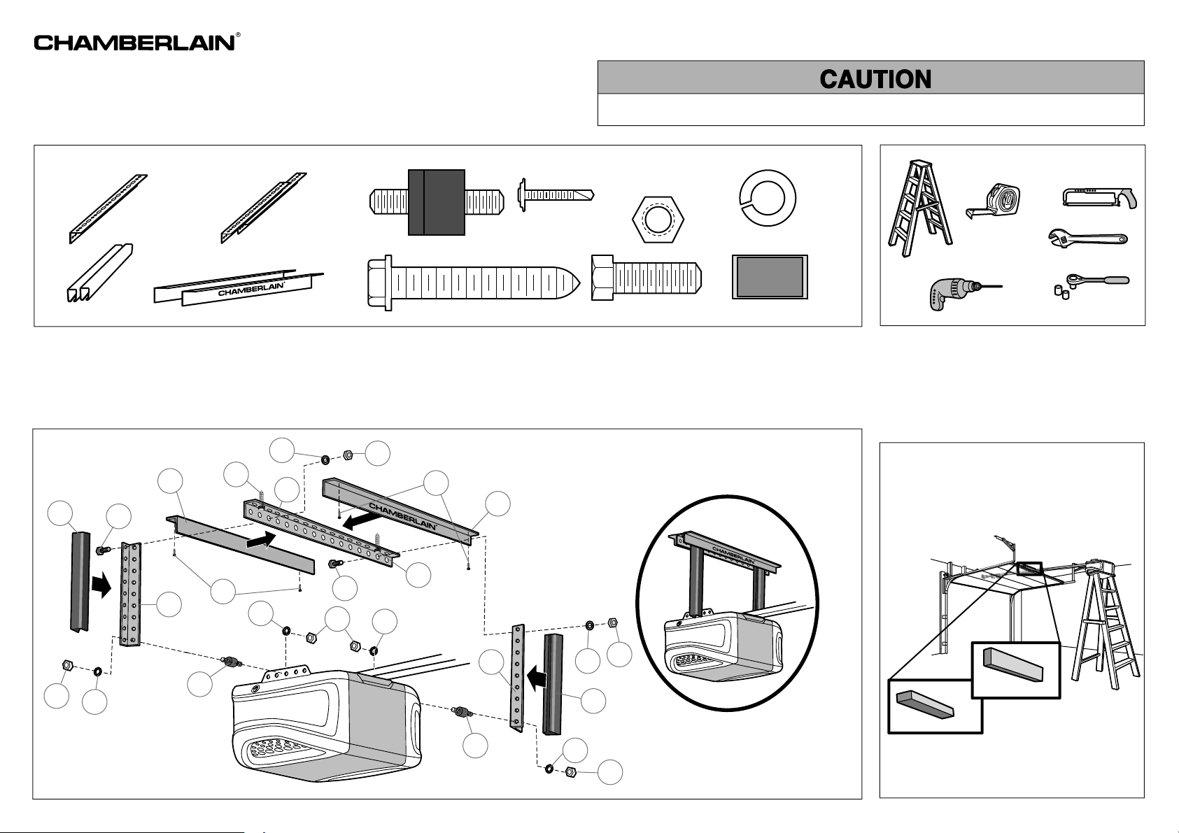
The Installation Upgrade Kit includes all components needed to hang garage door openers up to 24" from
the ceiling. The Installation Upgrade Kit works with ANY BRAND of garage door opener and gives openers a
fi nished look using premium components, hardware, and wire management. Vibration Isolator Bolts are also
included to make even the quietest garage door openers more silent within the home.
INSTALLATION UPGRADE KIT • MODEL BIK01
To prevent damage to garage door, rest garage door opener rail on 2x4 placed on top section of door.
CARTON INVENTORY:
(G) Nut
5/16"-18 (6)
(F) Lock Washer (6)
(I) Double Sided Tape (4)
(A) 32" Support
Bracket (1)
(C) 23" “C”-Shaped
Bracket Shields (2)
(D) 24" Hanging
Brackets (2)
(B) 32" Angled
Bracket Shields (2)
(J) Self-Threading
Screw (4)
(E) Vibration Isolation Bolts 5/16"-18 (2)
(H) Lag Screw 1-7/8" (2) (K) Hex Bolt 5/16"-18 x 7/8" (2)
Introduction
Assemble and install the garage door opener in accordance with the manufacturer’s instructions but STOP before positioning the garage door opener. Carefully and
safely remove all existing hanging brackets and hardware used with the previously installed garage door opener.
Overview
C
B
H
K
F
A
G
J
B
TOOLS NEEDED:
Ladder
2
1
Tape Measure
Drill with Phillips Screw
Bit and 5/16" bit
Position the garage door opener
21
NOTE: A 2x4 is ideal for setting the distance between
the rail and the door. If the ladder is not tall enough
you will need help at this point.
Remove any packing material and lift the garage
door opener onto a ladder. Fully open the door
and place a 2x4 (laid flat) under the rail. For
one-piece doors without tracks, lay the 2x4 on
its side.
Hacksaw
Adjustable Crescent
Wrench
Socket Wrench and
7/16" and 1/2" Sockets
D
F
J
K
G
F
G
D
F
All other
door types
E
H
G
F
E
C
One-piece door
without tracks
F
G
Page 2
3
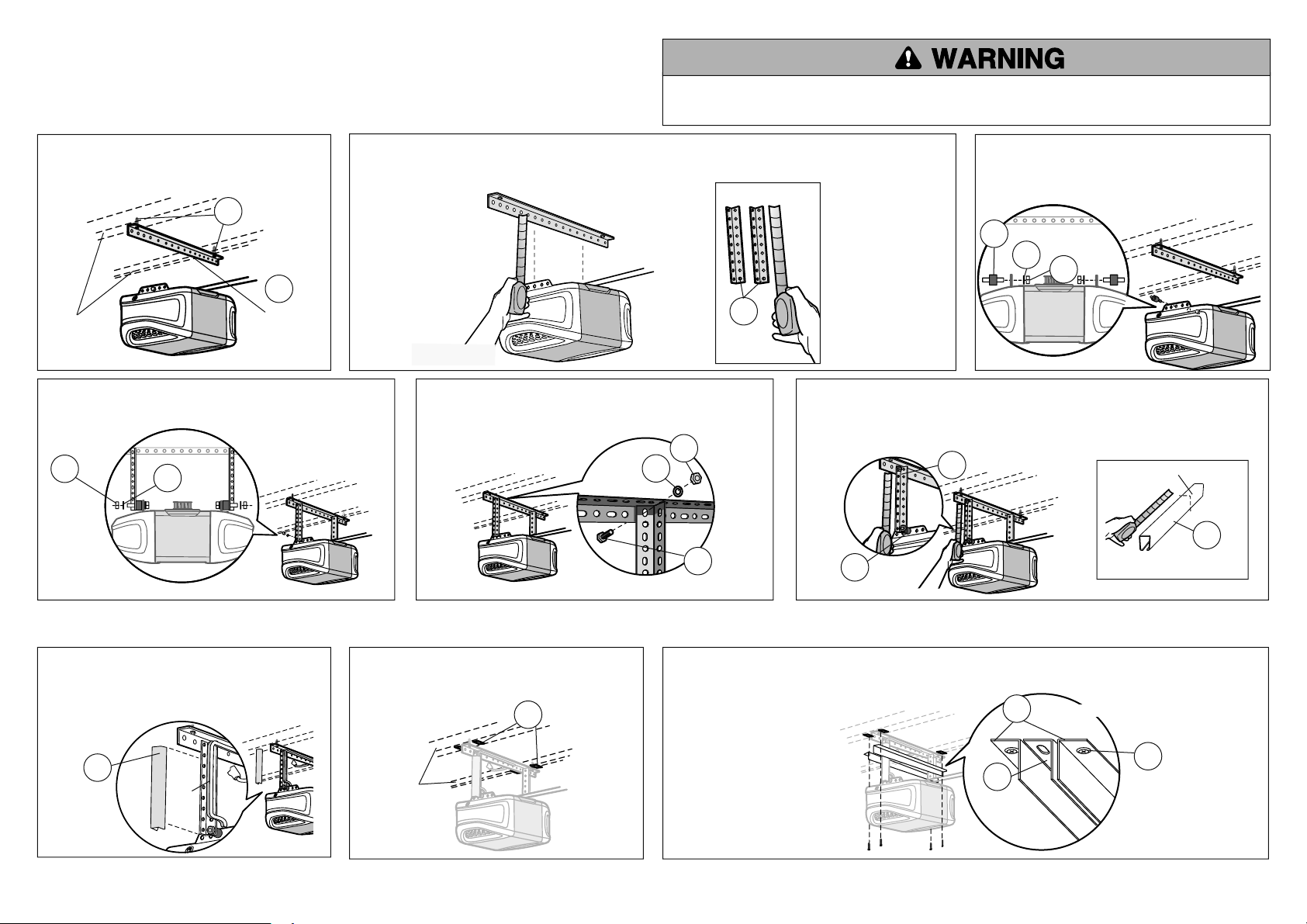
Hang the garage door opener
Hanging the garage door opener will vary depending on your garage. Your installation may be different. For
ALL installations the garage door opener MUST be connected to structural supports.
To avoid possible SERIOUS INJURY from a falling garage door opener, fasten it SECURELY to structural
supports of the garage. Concrete anchors MUST be used if installing ANY brackets into masonry.
3.1 Use lag screws (H) to attach the support
3.2 Make sure the garage door opener is aligned with the header bracket. Measure the distance from each
bracket (A) to the structural supports.
Lag Screw
H
A
Structural
Supports
32" Support
Bracket
3.4 Secure the hanging brackets to vibration isolator bolts
using lock washers (F) and nuts (G).
G
Nut
Lock
F
Washer
side of the garage door opener to the support bracket. Cut both hanging brackets (D) to the required
length.
D
Hanging
Brackets
3.5 Secure the hanging brackets to the support bracket using
the hex bolt (K), lock washers (F), and nuts (G).
3.6 Measure the distance between the support bracket and the vibration isolator
bolt. Cut both “C”-shaped bracket shields (C) to the required length. Finish
installing the garage door opener in accordance with the manufacturer’s
instructions BEFORE proceeding to Step 4.
E
Vibration Isolator Bolt
Lock
Washer
Nut
G
F
Hex Bolt
K
3.3 Insert the vibration isolation bolts (E) into
the garage door opener mounting holes that
align directly below the support bracket.
Secure with lock washers (F) and nuts (G).
Vibration Isolator Bolt
Hanging Brackets
D
E
Lock Washer
F
Nut
G
Cut
C
“C”-Shaped
Bracket Shields
Finish installation
4
4.1 Route the door control wires, safety sensor
wires, and power cord inside the hanging
bracket. Snap the bracket shield around the
hanging bracket to conceal the wires.
C
“C”-Shaped
Bracket Shields
Wires
4.2 Peel one side of the double sided tape (I)
and position the double sided tape on the
structural supports.
Double Sided Tape
I
Structural
Support
4.3 Peel the other side of the double sided tape and adhere to the bracket shields (B) as shown. Secure
the bracket shields to the ceiling or structural supports with the self-threading screws (J). Repeat for
opposite side.
B
A
32"
Support
Bracket
32" Bracket Shields
Self-Threading Screw
J
Page 3
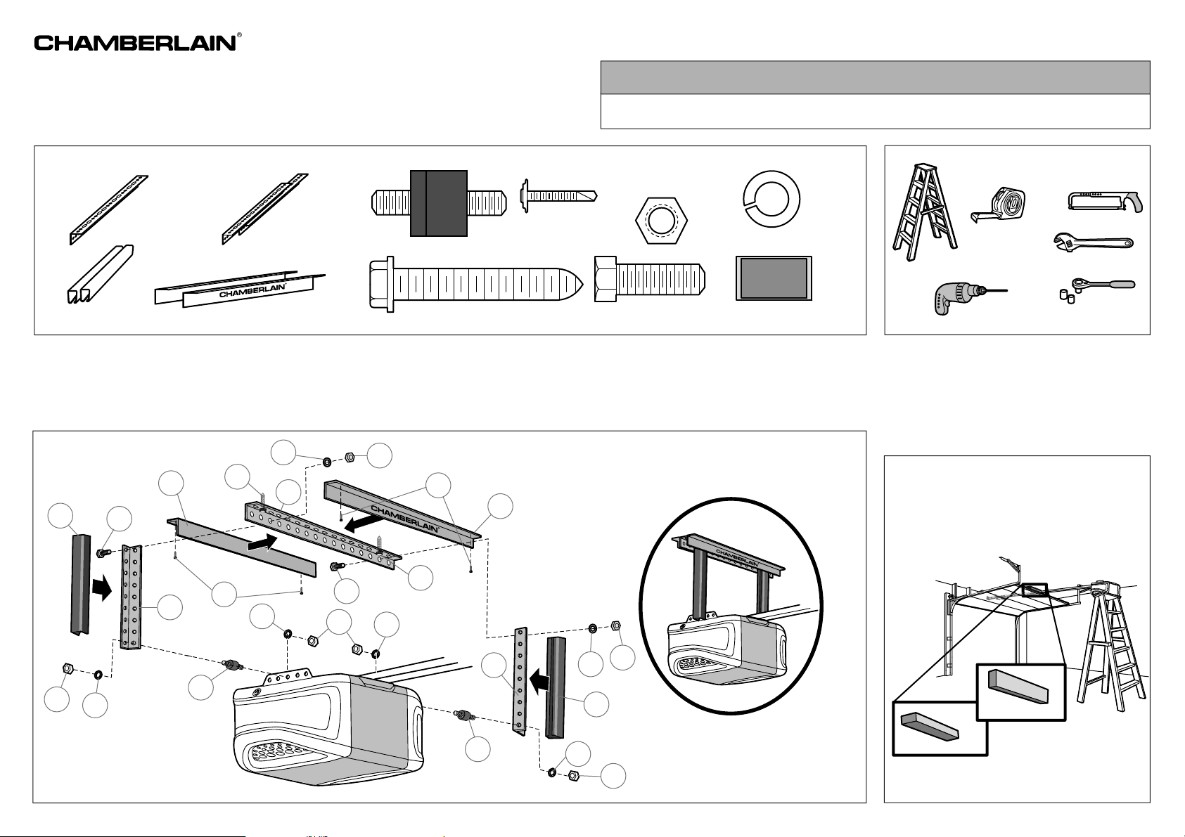
El juego de instalación tiene todos los componentes necesarios para colgar el abre-puerta a una altura de hasta
PRECAUCIÓNPRECAUCIÓN
60 cm (24 pulg.) del techo. El juego de instalación es compatible con CUALQUIER MARCA de abre-puerta de garaje.
Tiene componentes y accesorios de primer nivel que le confi eren un aspecto de refi nada terminación. Contiene pernos
amortiguadores de vibración que hacen aún más silencioso al más silencioso de los abre-puertas.
JUEGO DE INSTALACIÓN MODIFICADA • MODELO BIK01
Para evitar que la puerta del garaje sufra daños, apoye el riel del abre-puertas de garaje sobre un listón de madera de 2x4
colocado en la sección superior de la puerta.la partie supérieure de la porte.
(D) Ménsulas de suspensión
de 60 cm (24 pulg.) (2)
(A) Ménsula de soporte
de 81 cm (32 pulg.) (1)
(C) Tapas de perfil C de
58 cm (23 pulg.) para
ménsula (2)
(B) Tapas en ángulo de
81 cm (32 pulg.) para
ménsula (2)
(J) Tornillos
autorroscantes (4)
(E) Pernos antivibratorios de 5/16 de pulg.-18 (2)
(H) Tornillos tirafondo de
1-7/8 de pulg. (2)
(K) Pernos de cabeza hexagonal de
5/16 de pulg.-18 x 7/8 de pulg. (2)
(G) Tuercas de
5/16 de pulg.-18 (6)
(F) Arandelas de presión (6)
(I) Cinta adhesiva de
doble lado (4)
Introducción
Armar e instalar el sistema de abre-puerta según las instrucciones del fabricante, pero DETÉNGASE antes de colocar la unidad abre-puerta. Desmonte con cuidado todas las ménsulas de
soporte y los accesorios de fi jación del abre-puerta.
CONTENIDO DE LA CAJA:
Descripción general
C
K
B
H
F
A
G
J
B
HERRAMIENTAS NECESARIAS:
Escalera
2
1
Cinta métrica
Taladro, punta Phillips,
llave tubo de 5/16 de pulg.
Colocar en posición el
21
Sierra
Llave inglesa
Crescent
Llaves tubo de 7/16 de pulg.
y 1/2 de pulg.
abre-puerta del garaje
NOTA: Un listón de 2x4 es ideal para mantener la distancia
de separación entre el riel y la puerta. Si la escalera no es lo
sufi cientemente alta, va a necesitar ayuda.
Desembalar totalmente el abre-puerta y colocarlo sobre
la escalera. Abrir totalmente la puerta y colocar el listón
de madera (acostado) de 2x4 bajo el riel. En puertas de
una sola pieza sin rieles, colocar el listón de madera en
posición vertical.
D
F
E
G
F
J
K
G
F
G
D
E
F
Otros tipos
C
F
de puerta
Puerta de una sola
pieza sin rieles
G
H
Page 4
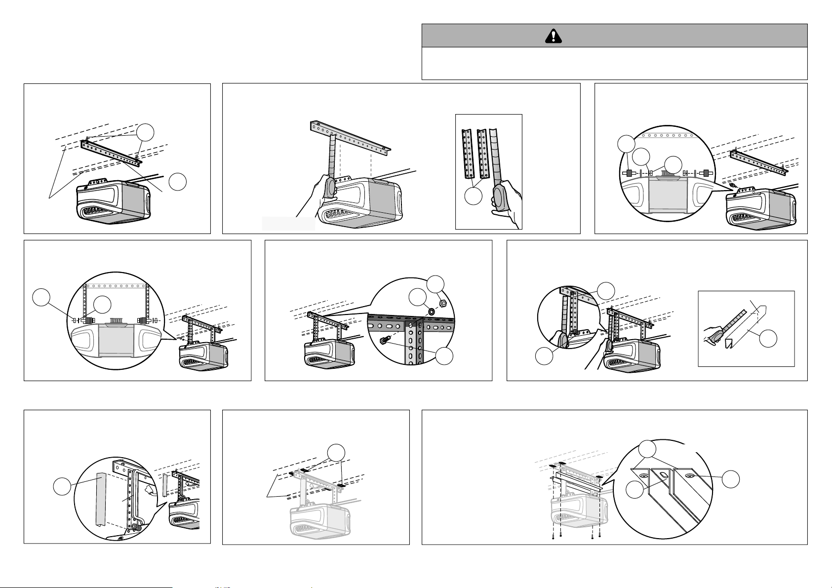
Colgar el abre-puerta del garaje
ADVERTENCIAADVERTENCIA
3
El montaje del abre-puerta puede variar según la estructura del garaje, por ello, la instalación en su caso podría ser
diferente. En TODAS las instalaciones, el abre-puerta DEBE estar conectado a los soportes estructurales.
Para evitar la posibilidad de una LESIÓN GRAVE si se cayera el abre-puertas de garaje, sujételo FIRMEMENTE a
los soportes estructurales del garaje. Se DEBEN usar anclajes para concreto si alguno de los soportes se va a instalar
en mampostería.
3.1 Fijar la ménsula (A) a los soportes estructurales
usando los tornillos tirafondo (H).
Tornillo tirafondo
H
3.2 El abre-puerta debe quedar alineado con la ménsula superior. Mida la distancia entre cada lado del
A
Soportes
estructurales
Ménsula de
soporte de
81 cm (32 pulg.)
3.4 Fije las ménsulas de suspensión a los pernos antivibratorios con
las arandelas de presión (F) y las tuercas (G).
Tuerca
G
F
Arandela
de presión
abre-puerta y la ménsula de soporte. Corte las ménsulas (D) a la medida necesaria.
D
Ménsulas
de suspensión
3.5 Fije las ménsulas de suspensión a la ménsula de soporte el
perno (K), las arandelas de presión (F) y las tuercas (G).
Tuerca
G
Arandela
de presión
F
Pernos de
K
cabeza
hexagonal
3.3 Coloque los pernos antivibratorios (E) en los agujeros
de montaje del abre-puerta que quedan alineados
directamente bajo la ménsula de soporte. Coloque y
ajuste las arandelas de presión (F) y las tuercas (G).
Perno antivibratorio
E
Arandela de presión
F
Tuerca
G
3.6 Mida la distancia entre la ménsula de soporte y el perno antivibratorio. Corte las tapas
de perfi l C (C) a la medida necesaria. Termine de instalar el abre-puerta según las
instrucciones del fabricante ANTES de ejecutar el Paso 4.
Ménsulas de suspensión
D
Corte
C
E
Perno antivibratorio
Tapas de perfil
C para ménsula
Terminar la instalación
4
4.1 Pasar los cables de control, de los sensores de
seguridad y el cordón de alimentación eléctrica por
la ménsula de suspensión. Colocar la tapa en la
ménsula de suspensión para ocultar los cables.
C
Tapas de perfil
C para ménsula
All Rights Reserved Printed in China
114A4391 Todos los derechos reservados Impreso en China
Cables
4.2 Quitar el revestimiento de un lado de la cinta
adhesiva (I) y colocar cinta en los soportes
estructurales.
Soportes
estructurales
Cinta adhesiva de
I
doble lado
© 2011, The Chamberlain Group, Inc.
4.3 Quitar el revestimiento del otro lado de la cinta y pegar las tapas de ménsula (B), tal como se muestra. Fijar
las tapas de ménsula al techo o a los soportes estructurales con los tornillos autorroscantes (J). Repetir el
procedimiento del otro lado.
Tapas de 81 cm (32 pulg.) para ménsula
B
Tornillo
J
A
Ménsula
de soporte de
81 cm (32 pulg.)
autorroscante
 Loading...