

Page 1

TM
OWNER’S MANUAL MODEL CB24
BEDIENUNGSANLEITUNG MODELL CB24
Serial # Arm 1
Seriennummer Arm 1
Serial # Arm 2
Seriennummer Arm 2
Serial # Box
Seriennummer Box
Installation Date
Installationsdatum
Konformitätserklärung
Electronic Control Model CB24
erfüllt die Anforderungen der geltenden
Abschitte der Normenvorschriften EN300220-3 • EN55014 • EN61000-3 • EN60555,
EN60335-1 • ETS 300 683 • EN60335-1: 2002 • EN60335-2-103: 2003 • EN55014-1:
2000 + A1 + A2 • EN55014-2: 2001 • EN61000-3-2: 2000 • EN61000-3-3: 1995 + A1 • EN
301 489-3, V1.3.1 • EN 300 220-3 V1.1.1 • EN 13241-1
sowie die Bestimmungen und sämtliche Ergänzungen
der EU-Vorschriften ..................................................73/23/EEC, 89/336EEC, 1999/5/EG
Einschlußerklärung
Die Steuerung, erfüllt die Bestimmungen der EU-Vorschrift 89/393/EEC und ihre
Ergänzungen, wenn sie gemäß den Anleitungen des Herstellers installiert und gewartet
wird und wenn sie mit einem Tor verwendet wird, das ebenfalls gemäß
Herstelleranleitungen installiert wurde und gewartet wird.
Die Unterzeichnende erklärt hiermit, dass das vorstehend
angegebenne Gerät sowie sämtliches im Handbuch aufgeführtes
Zubehör den oben genannten Vorschriften und Normen entspricht.
The Chamberlain Group, Inc
Elmhurst, IL 60126, USA
May, 2005
B. P. Kelkhoff
Manager, Test and Regulatory
Declaration of Conformity
Electronic Control Model CB24
are in conformity to the applicable
sections of StandardsEN300220-3 • EN55014 • EN61000-3 • EN60555, EN60335-1 • ETS
300 683 • EN60335-1: 2002 • EN60335-2-103: 2003 • EN55014-1: 2000 + A1 + A2 •
EN55014-2: 2001 • EN61000-3-2: 2000 • EN61000-3-3: 1995 + A1 • EN 301 489-3,
V1.3.1 • EN 300 220-3 V1.1.1 • EN 13241-1
per the provisions & all amendments
of the EU Directives ..................................................73/23/EEC, 89/336EEC, 1999/5/EG
Declaration of Incorporation
Electronic Control, when installed and maintained according to all the Manufacturer’s
instructions in combination with a Gate, which has also been installed and maintained
according to all the Manufacturer’s instructions, meets the provisions of EU Directive
89/392/EEC and all amendments.
I, the undersigned, hereby declare that the equipment
specified above and any accessory listed in the manual
conforms to the above Directives and Standards.
The Chamberlain Group, Inc
Elmhurst, IL 60126, USA
May, 2005
B. P. Kelkhoff
Manager, Test and Regulatory
Chamberlain GmbH • Alfred-Nobel-Str. 4 • D-66793 Saarwellingen
GB
D
TM
ALARM
MAGLOCK
GATE 1
ACCESSORY
POWER
GATE 2
J4
P2
D6
TIMER
RUNNING
D1
D4
D2
P1
TIMER TO
CLOSE
F7
C13
J18
U4
F6
F2
J19
K6
NO
C
NO
C
NC
Z1
10A 32V
BRN
GRN
WHT
YEL
BLU
RED
Z12
R9
24V
BRN
GRN
WHT
YEL
BLU
RED
D15
R196
C2R4
24 VAC/
SOLAR
INPUT
F3
D1
Ø
K1
Ø
10A 32V
MOV2
J1
K5
L1
S8
1
R2
LEARN
SINGLE
XMITTER
R1
2
K2
DIAGNOSTIC
SET
Q9
OPEN
LIMIT
Ø
1
R1
R1
ØØ
F4
ACCESSORY
OVLD
K4
F5
D21
K3
D8
D22
Q22
C11
MOV1
JMPR2
DB1
Ø
14GPØ89ØE
Ø
14LGØ89ØE
Ø
14SKØ89ØE
O
N
1 2 3 4 5
OFF
ON
OFF
NO
NO
FORCE
MIN MAX OFF MAX OFF MAX
C12
C64
SAVE
ON
MAGLOCK
DUAL
MODE
NC
EDGE
PHOTO
NC
S1
GATE 1
SET
LEARN
CLOSE
LIMITS
LIMIT
GATE 2
BIPART
DELAY
R35
D9
D27
Z3
Z4
U3
R9
JMPR1
U2
BUTTON
C4
SINGLE
Ø
7
R2
R224
SINGLE BUTTON
CHGR
OVLD
F1 2
FUSE
OPEN
Z2
Ø
R227
0
A 32V
R223
Z22
R92
R91
R94
R93
COM
OVLD
OPEN
RESET
STOP
POWER
SHADOW
INTERRUPT
24V
OVLD
BATT 1BATT 2
COM
COM
COM
CLOSE
EDGE
OPEN EDGE/
PHOTO
OPEN
PHOTO
CLOSE
PHOTO
SWITCHED
ACCESSORY
POWER
CONTROL
INPUTS
LOOP
INPUTS
Z9
Z8
Page 2
SPECIFICATIONS
Carton Inventory . . . . . . . . . . . . . . . . . . . . . . . . . . . . . . . . . . . . .2
Control Board Specifications . . . . . . . . . . . . . . . . . . . . . . . . . . . .2
WARNINGS
Safety Installation Information . . . . . . . . . . . . . . . . . . . . . . . . . . .3
Warnings and Precautions . . . . . . . . . . . . . . . . . . . . . . . . . . . . . .3
Suggested Entrapment Protection Device Locations . . . . . . . . . .4
WIRING
Control Box Mounting . . . . . . . . . . . . . . . . . . . . . . . . . . . . . . . . .5
Earth Ground Rod Installation . . . . . . . . . . . . . . . . . . . . . . . . . . .6
Control Wiring . . . . . . . . . . . . . . . . . . . . . . . . . . . . . . . . . . . . . . .7
Wiring Of Motor To Control Board . . . . . . . . . . . . . . . . . . . . . . . .9
BASIC CONTROL BOARD SETUP
Set Dip Switch for Gate Type . . . . . . . . . . . . . . . . . . . . . . . . . . . .9
Install Radio Module . . . . . . . . . . . . . . . . . . . . . . . . . . . . . . . . .10
Programming Remote . . . . . . . . . . . . . . . . . . . . . . . . . . . . . . . .10
Wire Stop Button . . . . . . . . . . . . . . . . . . . . . . . . . . . . . . . . . . . .10
Optional Control Devices . . . . . . . . . . . . . . . . . . . . . . . . . . .11-13
Force and Timer to Close . . . . . . . . . . . . . . . . . . . . . . . . . . . . . .14
Program Limits . . . . . . . . . . . . . . . . . . . . . . . . . . . . . . . . . . . . .14
DIP Switch Settings . . . . . . . . . . . . . . . . . . . . . . . . . . . . . . . . . .15
OPERATION and MAINTENANCE
First Use . . . . . . . . . . . . . . . . . . . . . . . . . . . . . . . . . . . . . . . . . . .16
Maintenance . . . . . . . . . . . . . . . . . . . . . . . . . . . . . . . . . . . . . . . .16
WIRING DIAGRAM
. . . . . . . . . . . . . . . . . . . . . . . . . . . . . . .17
TROUBLESHOOTING
. . . . . . . . . . . . . . . . . . . . . . . . . . .18-19
REPAIR PARTS
. . . . . . . . . . . . . . . . . . . . . . . . . . . . . . . . . . .20
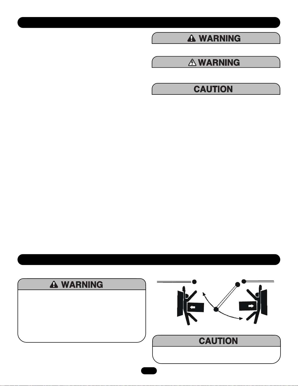
When you see these Safety Symbols and Signal Words on the
following pages, they will alert you to the possibility of serious
injury or death if you do not comply with the warnings that
accompany them. The hazard may come from something
mechanical or from electric shock. Read the warnings carefully.
When you see this Signal Word on the following pages, it will
alert you to the possibility of damage to your gate and/or the gate
operator if you do not comply with the cautionary statements that
accompany it. Read them carefully.
Mechanical
Electrical
TABLE OF CONTENTS
• BEFORE attempting to install, operate or maintain the operator,
you must read and fully understand this manual and follow all
safety instructions.
• These instructions are intended to highlight certain safety
related issues. These instructions are not intended to be
comprehensive. Because each application is unique, it is the
responsibility of the purchaser, designer, installer and end user
to ensure that the total gate system is safe for its intended use.
•
Save These Instructions
IMPORTANT NOTE
01-G0665F18
SAFETY PRECAUTIONS FOR SWING and ORNAME NTAL “GRILL TYPE GATES”
To pr ev ent SERIOUS INJU RY or DEAT H from a moving gate:
• Entrapment protection devices MUST be installed to protect
anyone who may come near a moving gate.
• Locate entrapment protection devices to protect in BOTH the open
and close gate cycles.
• Locate entrapment protection devices to protect between moving
gate and RIGID objects, such as posts.
• A swinging gate shall NOT open into public access ways
INSTALLATION
We recommend to use E-locks/Maglock against vandilism and if gate
is installed where strong winds may appear.
2
Page 3

LY N3 00 -2 4 W in g G at e O pe ra t or 2 4V ol t/ 2 50 kg /2 .5 m
LY N4 00 -2 4 W in g G at e O pe ra t or 2 4V ol t/ 2 50 kg /4 .0 m
SCS300-24 Wing Gate Operator 24Volt/250kg/3.0m
LA400-JB40 Extensioncable Kit 12m (page 6)
600206-24 Solar Panel 24 Volt
041ASWG-0479 Post bracket for round posts/piece
50-19503 Post bracket for gates opening to outside
(push to open)/piece
Battery Charger Supply . . . . . . . . . . . . . . . . . . . . . . . . .26Vac, 29VA
Solar Panel Supply (Optional) . . . . . . . . . . . . .27.4V, 9W (Minimum)
Temperature . . . . . . . . . . . . . . . . . . . . . . . . . . . . . . . .-20
o
C to + 55oC
Battery 12V/7AH . . . . . . . . . . . . . . . . . . . . . . . . . . . .-15
o
C to + 55oC
Electronic Control . . . . . . . . . . . . . . . . . . . . . . . . . . . . . . . . . . . .IP44
Main Supply (Control) Dedicated
Circuit . . . . . . . . . . . . . . . . . . . . . . . . . . . . . . . .230V~240V/50~60Hz
Absorbed Power . . . . . . . . . . . . . . . . . . . . . . . . . . . . . . . .0.75 Watts
Protection Fuse Gate 1 . . . . . . . . . . . . . . . . . . . . . . . . . . . . .ATC 10A
Protection Fuse Gate 2 . . . . . . . . . . . . . . . . . . . . . . . . . . . . .ATC 10A
Protection Fuse Battery . . . . . . . . . . . . . . . . . . . . . . . . . . . .ATC 20A
CARTON INVENTORY
3
CB24K KIT
1x PVC – Box
1x CB24-Logic Board (pre-mount)
1x Charge transformer (pre-mount)
2x 12Volt Batteries & wires (pre-mount)
1x 771E IR-sensor
CB24R KIT
1x PVC – Box
1x CB24-Logic Board (pre-mount)
1x Run transformer (pre-mount)
1x IR-sensor (771E)
CAK-1 COMMON ACCESSORY KIT
1x RF module 433.92MHz
2x Transmitter 3-channel 94335E
1x Key switch
1x Flashing Light (FLA24-2)
1x Antenna
INVENTORY & SPECIFICATIONS
SAFETY INSTALLATION INFORMATION
Warning - To reduce the risk of SEVERE INJURY or DEATH from an incorrect installation:
1. Vehicular gate systems provide convenience and security. Gate systems are comprised of many component parts. The gate operator is only one
component. Each gate system is specifically designed for an individual application.
2. Gate operating system designers, installers and users must take into account the possible hazards associated with each individual application.
Improperly designed, installed or maintained systems can create risks for the user as well as the bystander. Gate systems design and installation
must reduce public exposure to potential hazards.
3. A gate operator can create high levels of force in its function as a component part of a gate system. Therefore, safety features must be
incorporated into every design. Specific safety features include:
• Gate Edges • Guards for exposed rollers • Photoelectric Sensors
• Screen Mesh • Vertical Posts • Instructional and Precautionary Signage
4. Install the gate operator only when:
a. The operator is appropriate for the construction and the usage class of the gate.
b. All openings of a horizontal swing gate are guarded or screened from the bottom of the gate to a minimum of
4' (1.2 m) above the ground to prevent a 2 1/4" (6 cm) diameter sphere from passing through the openings anywhere in the gate, and in that
portion of the adjacent fence that the gate covers in the open position.
c. All exposed pinch points are eliminated or guarded, and guarding is supplied for exposed rollers.
5. The operator is intended for installation only on gates used for vehicles. Pedestrians must be supplied with a separate access opening.
6. The gate must be installed in a location so that enough clearance is supplied between the gate and adjacent structures when opening and closing
to reduce the risk of entrapment. Swinging gates shall not open into public access areas.
7. The gate must be properly installed and work freely in both directions prior to the installation of the gate operator.
8. Controls must be far enough from the gate so that the user is prevented from coming in contact with the gate while operating the controls.
9. Controls intended to be used to reset an operator after 2 sequential activations of the entrapment protection device or devices must be located in
the line of sight of the gate, or easily accessible controls shall have a security feature to prevent unauthorized use.
10. All warning signs must be installed where visible, on each side of the gate.
11. For a gate operator utilizing a non-contact sensor:
a. Reference owner’s manual regarding placement of non-contact sensor for each type of application.
b. Care shall be exercised to reduce the risk of nuisance tripping, such as when a vehicle trips the sensor while the gate is still moving.
c. One or more non-contact sensors shall be located where the risk of entrapment or obstruction exists, such as the perimeter reachable by a
moving gate or barrier.
12. For a gate operator utilizing a contact sensor such as an edge sensor:
a. A hard wired contact sensor shall be located and its wiring arranged so the communication between the sensor and the gate operator is not
subject to mechanical damage.
b. A wireless contact sensor such as the one that transmits radio frequency (RF) signals to the gate operator for entrapment protection functions
shall be located where the transmission of the signals are not obstructed or impeded by building structures, natural landscaping or similar
obstruction. A wireless contact sensor shall function under the intended end-use conditions.
c. One or more contact sensors shall be located at the leading edge, trailing edge and post mounted both inside and outside of a vehicular
horizontal slide gate.
d. One or more contact sensors shall be located at the bottom edge of a vehicular vertical lift gate.
e. One or more contact sensors shall be located on the inside and outside leading edge of a swing gate. Additionally, if the bottom edge of a
swing gate is greater than 6" (15 cm) above the ground at any point in its arc of travel, one or more contact sensors shall be located on the
bottom edge.
Page 4
4
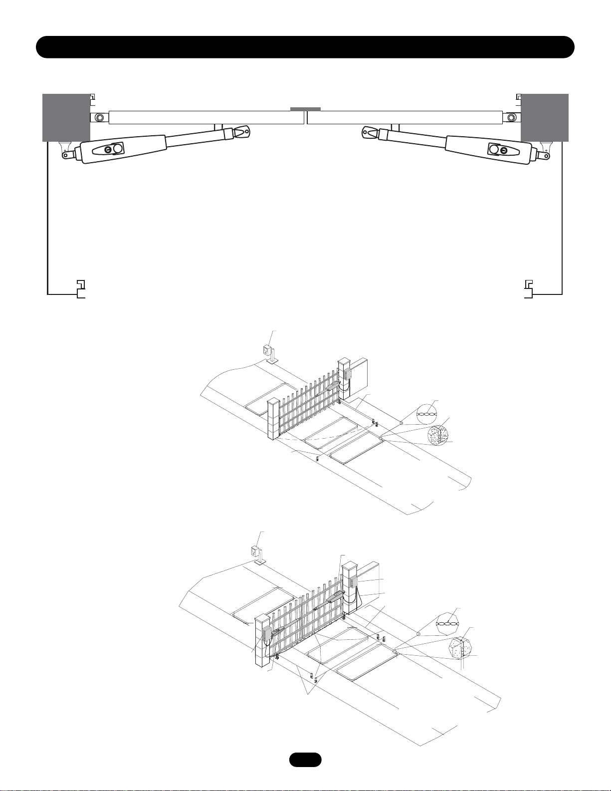
SUGGESTED ENTRAPMENT PROTECTION DEVICE LOCATIONS
SINGLE SWING GATE SYSTEM
DUAL SWING GATE SYSTEM
MAIN PROTECTION, WITH 2 PAIR OF PHOTOCELLS
Other options:
Complex or Parking Lot
1. Telephone Entry System
2. Photo Eye for Open Cycle
3. Run Twisted Wire* from Loop
to Operator
4. Seal Loops*
5. Loop Copper Wire
6. Interrup Loop
7. Shadow Loop
Complex or Parking Lot
1. Telephone Entry System
2. Gate 2
3. Junction Box
4. Extension Cable
5. Photo Eye for Open Cycle
6. Run Twisted Wire* from Loop
to Operator
7. Seal Loops
8. Loop Copper Wire
9. Interrupt Loop
10. Shadow Loop
11. Control Box
12. Gate 1
INSTALL ALL EQUIPMENT IN COMPLIANCE WITH EN60335-2-103, EN13241-1.
>>>>>>>>>>>>>>>>>>>>>>>>>>>>>>>>>>>>>>>>>>>>>>>>>>>>>>>>>>>>>>>>>>>>>>>>>>>>
<<<<<<<<<<<<<<<<<<<<<<<<<<<<<<<<<<<<<<<<<<<<<<<<<<<<<<<<<<<<<<<<<<<<<<<<<<<<<
Primary Photocell For Closing
>>>>>>>>>>>>>>>>>>>>>>>>>>>>>>>>>>>>>>>>>>>>>>>>>>>>>>>>>>>>>>>>>>>>>>>>>>>>>
<<<<<<<<<<<<<<<<<<<<<<<<<<<<<<<<<<<<<<<<<<<<<<<<<<<<<<<<<<<<<<<<<<<<<<<<<<<<<
Photocell For Opening
1
6
1
9
11
12
2
7
2
5
6
2
3
4
5
10
9
3
4
5
6
7
8
Page 5
5
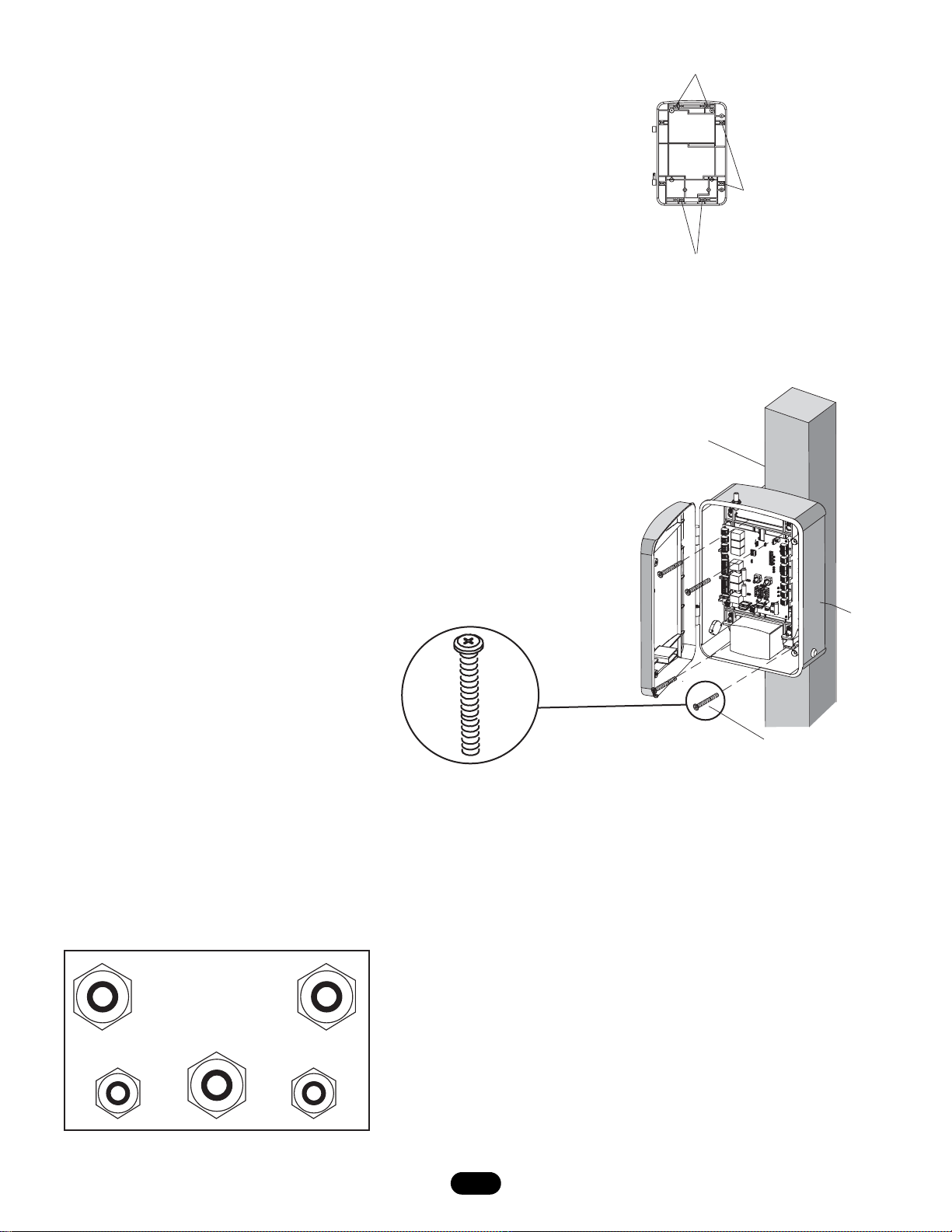
CONTROL BOX MOUNTING
1. Determine the spacing required for mounting and select the
proper holes to be used for mounting (Figure 1).
2. Knockout plastic from holes using screw driver.
Insert the strain reliefs (Figure 3).
3. Place box up against the mounting surface. Insert the screws
through the mounting holes in back and secure in place
(Figure 2).
STRAIN RELIEF
(1) Screw Spacing 101.6mm (4”)
(2) Screw Spacing 152.4mm (6”)
(3) Screw Spacing 63.5mm (2-1/2”)
(1) Mounting Post
(2) E-Box
(3) Mounting Screws (4 pieces)
1
Figure1
2
3
1
Figure 2
Figure 3
2
3
Page 6
230Vac POWER WIRE
(STRANDED COPPER WIRE)
NOTE: Calculated using NEC guidelines. Local codes and conditions must be reviewed for suitability of wire installation.
To r educe the r isk of SEVER E INJURY or DE ATH:
• ANY maintenance to the operator or in the area near the
operator MUST not be performed until disconnecting the
electrical power and locking-out the power via the operator
power switch. Upon completion of maintenance the area MUST
be cleared and secured, at that time the unit may be returned
to service.
• Disconnecting power at the fuse box BEFORE proceeding.
Operator MUST be properly grounded and connected in
accordance with local electrical codes.
NOTE: The operator
should be on a separate fused line of adequate capacity.
• ALL electrical connections MUST be made by a qualified
individual.
• DO NOT install any wiring or attempt to run the operator
without consulting the wiring diagram. We recommend that
you Install an optional reversing edge BEFORE proceeding with
the control station installation.
• ALL power wiring should be on a dedicated circuit and well
protected. The location of the power disconnect should be
visible and clearly labeled.
• ALL power and control wiring MUST be run in separate
conduit.
• BEFORE installing power wiring or control stations be sure to
follow all specifications and warnings described below. Failure
to do so may result in SEVERE INJURY to persons and/or
damage to operator.
Wire Gauge
0.75/1.5mm
2
1.5mm
2
Length
50m
100m
WIRING
6
EARTH GROUND ROD INSTALLATION
Attach ground wire to control
box.
System must be grounded. In case no ground wire is available
a ground rod must be installed. Follow the local applicable
standards of EN or IEC.
1
All power wiring should be on a dedicated circuit and well protected.
24Vac TRANSFORMER
(STRANDED COPPER WIRE)
Wire Gauge
0.75/1.5mm
2
1.5mm
2
Length
50m
100m
LA400-JB40 MOTOR
EXTENSION CABLE KIT
(OPTIONAL)
Kit Contains:
(1) 12m cable with terminals
(1) Junction box IP65
(2) Strain reliefs PG 13,5
(1) Mounting hardware
(1) Control Box
1
3
2
Page 7

7
MOV2
24 VAC/
SOLAR
INPUT
J4
BATT 2
BATT 1
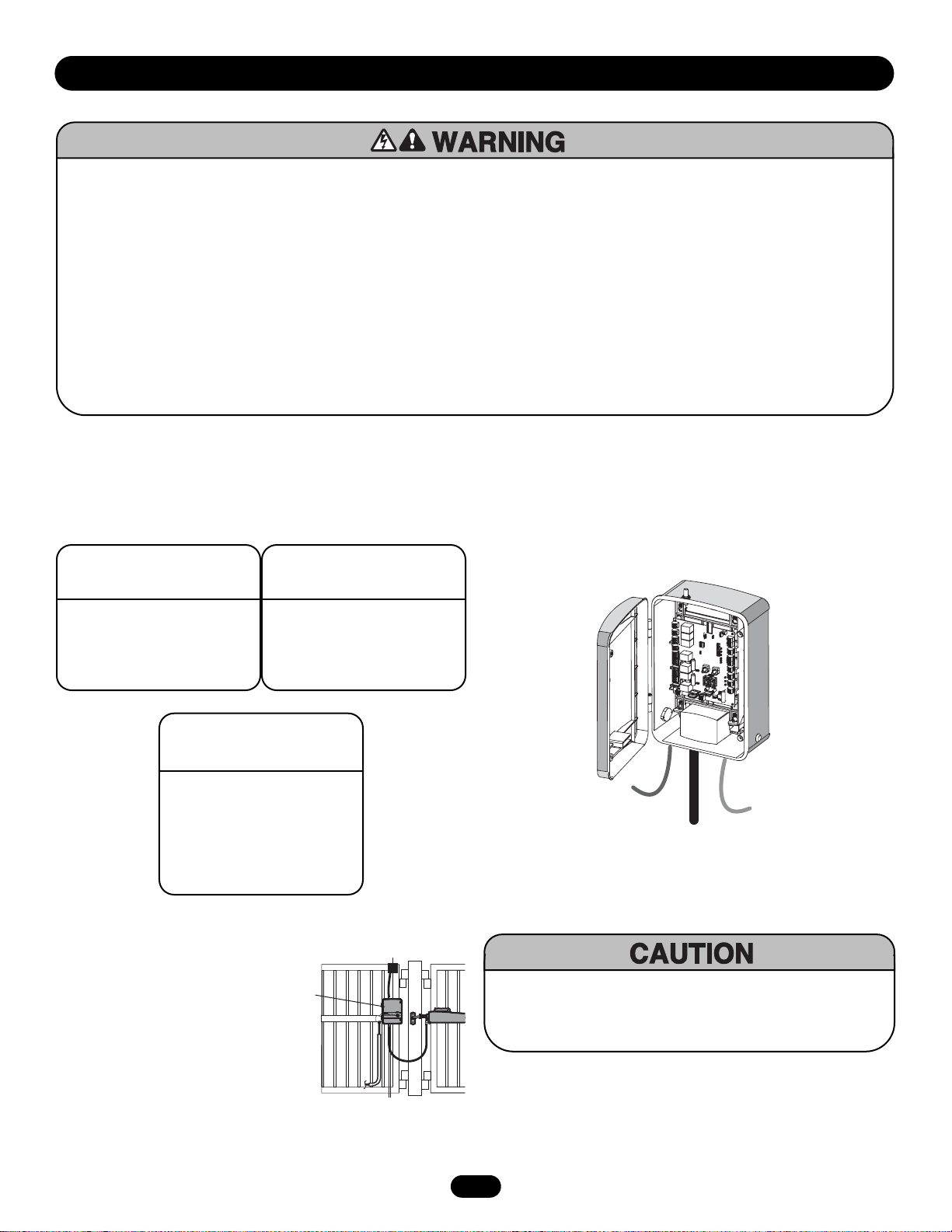
BATTERY WITH CHARGE TRANSFORMER
The main source of power are the batteries. The batteries
can be charged in circuit by using a charging transformer
or solar panels.
CONTROL WIRING
POWER IN
The 24Vac input can accept a charging transformer or the run
transformer. Ideally the charge transformer is installed at the
house and a low voltage line is used to the control board at the
gate.
The run transformer is installed in the control box.
SOLAR PANELS
Optional solar panels may be used to charge the batteries. Solar
Panels must be a minimum of 27.4V, 9W output.
To r educe the r isk of FIRE or I NJURY to perso ns use only
Chamberlain parts for replacement batteries.
BATTERY WITH RUN TRANSFORMER
The main source of power is the transformer.
The batteries may or may not be used. Batteries
if installed function as back-up to open the gate
in case of a power outage.
Transfor mer must be re moved fr om the backside of the control board if batteries are installed.
GROUND
ALARM
MAGLOCK
GATE 1
ACCESSORY
POWER
GATE 2
J4
GREEN/YELLOW
J19
NO
C
NO
C
NC
Z1
BRN
GRN
WHT
YEL
BLU
RED
BRN
GRN
WHT
YEL
BLU
RED
C2R4
K6
10A 32V
Ø
D1
Z12
R9
Ø
24V
10A 32V
D15
R196
24 VAC/
SOLAR
INPUT
MOV2
J1
K5
L1
S8
1
OFF
R2
OFF
LEARN
SINGLE
XMITTER
R1
NO
NO
2
F3
K2
DIAGNOSTIC
SET
K1
Q9
OPEN
LIMIT
Ø
1
ØØ
F4
ACCESSORY
OVLD
K4
MIN MAX OFF MAX OFF MAX
F5
D21
K3
D8
D22
Q22
C11
MOV1
C64
JMPR2
DB1
FORCE
C12
U2
R1
R1
P2
Ø
14GPØ89ØE
Ø
14LGØ89ØE
Ø
14SKØ89ØE
O
N
1 2 3 4 5
ON
SAVE
ON
MAGLOCK
DUAL
MODE
NC
EDGE
NC
PHOTO
S1
GATE 1
SET
LEARN
CLOSE
LIMITS
LIMIT
TIMER
GATE 2
RUNNING
BIPART
TIMER TO
DELAY
CLOSE
R35
D9
D27
Z3
F7
Z4
U3
D4
R9
D1
JMPR1
D2
D6
R223
P1
Ø
7
R2
Z2
R227
J18
R224
U4
SINGLE
BUTTON
SINGLE BUTTON
C13
C4
CHGR
OVLD
F6
F2
Ø
F1 2
FUSE
OPEN
Ø
Z22
R92
R91
R94
R93
POWER
SHADOW
INTERRUPT
A 32V
CLOSE
EDGE
OPEN EDGE/
PHOTO
Z9
OPEN
PHOTO
Z8
CLOSE
PHOTO
24V
SWITCHED
ACCESSORY
COM
OVLD
POWER
OVLD
CONTROL
INPUTS
OPEN
RESET
STOP
COM
COM
LOOP
INPUTS
COM
BATT 1BATT 2
(Optional)
150VA
TORROID
TRANSFORMER
USE DEDICATED CIRCUIT
OR
Page 8

8
Z22
R91
CLOSE
EDGE
R94
R92
R93
L1
R1
R2
Z1
K5
Ø
14GPØ89ØE
Ø
14LGØ89ØE
Ø
14SKØ89ØE
K6
K2
F3
10A 32V
D1
Ø
OPEN EDGE/
PHOTO
OPEN
PHOTO
CLOSE
PHOT
O
J18
R227
R2
Ø
7
Z2
Ø
R223
P1
Z9
Z8
F2
F6
D4
D2
R9
C64
JMPR1
R224
U4
P2
J1
J19
SINGLE
BUTTON
CONTROL
INPUTS
FORCE
BIPART
DELAY
TIMER TO
CLOSE
MIN MAX OFF MAX OFF MAX
OPEN
SINGLE BUTTON
RESET
STOP
SHADOW
S1
INTERRUPT
CHGR
OVLD
COM
COM
COM
FUSE
OPEN
LOOP
INPUTS
POWER
BATT 1BATT 2
F1 2
0
A 32V
R35
D9
Z3
Z4
U3
D1
D27
F5
C11
C13
C12
D15
C2R4
R1
Ø
1
R1
ØØ
R9
Ø
Q9
K1
R196
Q22
D8
K3
K4
D21
D22
C4
ACCESSORY
OVLD
D6
JMPR2
MOV1
MOV2
DB1
U2
Z12
24 VAC/
SOLAR
INPUT
GATE 2
ACCESSORY
POWER
MAGLOCK
ALARM
GATE 1
C
C
NC
NO
NO
GRN
WHT
YEL
BLU
RED
BRN
GRN
WHT
YEL
BLU
RED
BRN
F4
10A 32V
F7
24V
24V
COM
OVLD
OVLD
SWITCHED
ACCESSORY
POWER
TIMER
RUNNING
GATE 2
SET
OPEN
LIMIT
SET
CLOSE
LIMIT
LEARN
LIMITS
DIAGNOSTIC
GATE 1
J4
SAVE
MAGLOCK
MODE
EDGE
PHOTO
OFF
OFF
SINGLE
NO
NO
ON
ON
DUAL
NC
NC
LEARN
XMITTER
S8
1 2 3 4 5
O
N
2
1
14
13
12
20
11*
10
2
LED A
3
5
4
6*
22
7
8
18
17
19
1
9 23 24 25 15
16
LED P
LED Q
LED R
LED S
LED T
LED U
21
26
LED C
LED D
LED E
LED F
LED G
LED H
LED I
LED J
LED K
LED L
LED M
LED N
LED O
LED B
LED V
LED W
LED X
LED Y
LED Z
27
BASIC CONTROL BOARD SETUP
ITEM DESCRIPTION FUNCTION
1Connector P1 Antenna Input
2Connector P6 Close Edge
3Connector P8 Open Edge/Photo
4Connector P7 Open Photo
5Connector P9 Close Photo
6Connector P12 Switched Accessory Power
7Connector P10 Control Inputs
8Connector P11 Loop Inputs
9Connector P5 24Vac/Solar Input
10 Connector P16 Gate 2
11 Connector P13 Accessory Power
12 Connector P17 Gate 1
13 Connector P14 Maglock/Solenoid
14 Connector P15 Alarm
15 Connector Battery 1
16 Connector Battery 2
18 Pushbutton Learn Xmitter - Program Remote
Button 1 To Open Gate 1
Button 2 To Open Gate 1 and Gate 2
19 Pushbuttons Gate 1 - Jog Learn Limit
20 Pushbutton Learn Limits
21 Pushbuttons Gate 2 - Jog Learn Limit
22 Pushbutton Single Button
23 Potentiometer Force
24 Potentiometer BiPart Delay
25 Potentiometer Timer To Close
26 Connector Earth
27 Radio Socket Radio Module
*Maximum 300 mA combined output
LED DESCRIPTION
RED LED should be “Off” or indicate a fault to resolve (Example: Photocell activated or
shortened wire).
GREEN LED should be “On” to indicate “OK”.
ITEM DESCRIPTION
LED A Red Edge for closing
LED B Red Edge/photo for opening
LED C Red Photo for opening
LED D Red Photo for closing
LED E Red Accessory current overload
LED F Red COM overload
LED G Red Timer to close run indicator
LED H Red Open gate command
LED I Red Open gate command
LED J Red Reset Function button
LED K Green Stop Button
LED L Green Logic board general power
LED M Green Shadow loop
LED N Green Interrupt loop
LED O Red Charger Overload
LED P Red Battery fuse open
LED Q Red Accessory overload
LED R Red Gate 2 Limit indicator
LED S Red Gate 2 Limit indicator
LED T Red Gate 1 Limit indicator
LED U Red Gate 1 Limit indicator
LED V Red E-Lock/Maglock relay indicator
LED W Red Alarm/Flashing light relay indicator
LED X Green Diagnostic (see troubleshooting section)
LED Y Red Transmitter learn indicators
LED Z Red Open/Close programming indicator
Page 9

S1
SAVE
MAGLOCK
MODE
EDGE
PHOTO
OFF
OFF
SINGLE
NO
NO
ON
ON
DUAL
NC
NC
1 2 3 4 5
O
N
SET DIP SWITCH FOR GATE TYPE
1. The Save switch must be set to the OFF position prior to
setting or changing the switches.
2. Set switch to Single for single gate installation. For Dual
(Gate 1 and 2) installation set switch on Dual.
3. Set the Save switch to ON to save the setting.
NOTE: When setting switches S2-5 the save switch must be in
the off position prior to setting or changing switches for the
change to be saved.
WIRING OF MOTOR 1 & 2 INTO THE CONTROL BOARD
Connect gate that opens first to terminal “Gate 1”, the other to
terminal “Gate 2”.
NOTE: Connect color correctly. Watch out if you use splitter
boxes.
9
ALARM
MAGLOCK
GATE 1
ACCESSORY
POWER
GATE 2
P2
LEARN
LIMITS
R35
JMPR1
SAVE
MAGLOCK
MODE
EDGE
PHOTO
BIPART
DELAY
D9
Z3
Z4
P1
TIMER
RUNNING
TIMER TO
CLOSE
F7
C13
U3
D4
D1
D2
D6
J19
NO
C
NO
C
NC
Z1
BRN
GRN
WHT
YEL
BLU
RED
Z12
BRN
GRN
WHT
YEL
BLU
RED
C2R4
J4
K6
K5
L1
S8
1
R2
LEARN
XMITTER
10A 32V
R9
24V
D15
R196
24 VAC/
SOLAR
INPUT
R1
2
F3
Ø
D1
K2
SET
K1
Q9
OPEN
10A 32V
LIMIT
Ø
1
R1
R1
ØØ
F4
ACCESSORY
OVLD
K4
F5
D21
K3
D8
D22
Q22
MOV1
JMPR2
DB1
Ø
MOV2
Ø
14GPØ89ØE
Ø
14LGØ89ØE
Ø
14SKØ89ØE
J1
O
N
1 2 3 4 5
OFF
ON
OFF
ON
SINGLE
DUAL
NO
NC
NO
NC
S1
DIAGNOSTIC
GATE 1
SET
CLOSE
LIMIT
GATE 2
FORCE
MIN MAX OFF MAX OFF MAX
C12
D27
C11
R9
C64
U2
R223
CLOSE
Z22
R92
R91
R94
R93
OVLD
RESET
POWER
SHADOW
INTERRUPT
24V
COM
OVLD
OPEN
STOP
COM
COM
COM
BATT 1BATT 2
EDGE
OPEN EDGE/
PHOTO
Z9
OPEN
PHOTO
Z8
CLOSE
PHOTO
SWITCHED
ACCESSORY
POWER
CONTROL
INPUTS
SINGLE
LOOP
INPUTS
OFF
OFF
SINGLE
NO
NO
OFF
OFF
NO
NO
O
N
1 2 3 4 5
O
N
1 2 3 4 5
ON
ON
DUAL
NC
NC
ON
ON
DUAL
NC
NC
Ø
7
R2
Z2
Ø
R227
J18
R224
U4
SINGLE
BUTTON
SINGLE BUTTON
C4
CHGR
OVLD
F6
F2
F1 20A 32V
FUSE
OPEN
1 Brown
2 Green
3 White
4 Yellow
5 Blue
6 Red
Page 10

10
COM
COM
CONTROL
INPUTS
OPEN
SINGLE BUTTON
RESET
STOP
POWER
WIRE STOP BUTTON (OPTIONAL)
A jumper wire is factory installed between the stop and common input.Stop (N/C) - Stop only (does not reset alarm)
PROGRAMMING REMOTE
1.Press LEARN XMITTER button (LED will light up).
2.Press remote button, the LED will flash, alarm output will
activate twice.
3. Repeat steps 1 and 2 until all remotes are programmed
(50 remotes maximum total).
NOTE: For highest level of security, we recommend the Rolling
Code line of products.
XMITTER button 1 will open Gate 1 only.
XMITTER button 2 will open both gates with one command
from the remote control.
COMPATIBLE REMOTES - 433MHz
Billion Code Remotes Rolling CodesRemotes
4330E 94330E
4333E 94333E
4335E 94335E
4332E (1 x Dip)
Keypads Rolling Codes Keypad
747E 9747E
L
i
f
t
M
a
s
t
e
r
L1
R1
R2
Z1
K5
Ø
14GPØ89ØE
Ø
14LGØ89ØE
Ø
14SKØ89ØE
K6
K2
F3
10A 32V
D1
Ø
P1
P2
J1
J19
S1
Q9
K1
Z12
MAGLOCK
ALARM
GATE 1
C
C
NC
NO
NO
GRN
WHT
YEL
BLU
RED
BRN
SET
OPEN
LIMIT
SET
CLOSE
LIMIT
LEARN
LIMITS
DIAGNOSTIC
GATE 1
SAVE
MAGLOCK
MODE
EDGE
PHOTO
OFF
OFF
SINGLE
NO
NO
ON
ON
DUAL
NC
NC
1 2 3 4 5
O
N
LEARN
XMITTER
2
1
LEARN
XMITTER
2
1
INSTALL PLUG-IN RADIO RECEIVER MODULE
DELETE REMOTE
1.Press LEARN XMITTER button (LED will light up) and
hold until LED is off.
Transmit ter Memor y is era sed.
ALARM
MAGLOCK
Z1
GATE 1
ACCESSORY
POWER
GATE 2
J4
NO
C
NO
C
NC
10A 32V
BRN
GRN
WHT
YEL
BLU
RED
Z12
R9
24V
BRN
GRN
WHT
YEL
BLU
RED
D15
R196
C2R4
24 VAC/
SOLAR
INPUT
P2
R35
JMPR1
D9
Z3
Z4
BIPART
DELAY
SAVE
MAGLOCK
MODE
EDGE
PHOTO
U3
D1
D6
TIMER
RUNNING
D4
TIMER TO
D2
CLOSE
F7
P1
C13
J19
K6
K5
L1
S8
1
R2
LEARN
XMITTER
R1
2
F3
D1
Ø
K2
SET
K1
Q9
OPEN
Ø
LIMIT
R1
Ø
1
ØØ
R1
F4
ACCESSORY
10A 32V
OVLD
K4
F5
D21
K3
D8
D22
Q22
MOV2
MOV1
JMPR2
DB1
Ø
14GPØ89ØE
Ø
14LGØ89ØE
Ø
14SKØ89ØE
J1
O
N
1 2 3 4 5
OFF
ON
OFF
ON
SINGLE
DUAL
NO
NC
NO
NC
S1
DIAGNOSTIC
GATE 1
SET
LEARN
CLOSE
LIMITS
LIMIT
GATE 2
FORCE
MIN MAX OFF MAX OFF MAX
C12
D27
C11
R9
C64
U2
R223
CLOSE
Z22
R92
R91
R94
R93
COM
OVLD
RESET
POWER
SHADOW
INTERRUPT
EDGE
OPEN EDGE/
PHOTO
Z9
OPEN
PHOTO
Z8
CLOSE
PHOTO
24V
SWITCHED
ACCESSORY
OVLD
POWER
CONTROL
INPUTS
OPEN
STOP
COM
COM
LOOP
INPUTS
COM
BATT 1BATT 2
Ø
7
R2
Ø
Z2
R227
J18
R224
U4
SINGLE
BUTTON
SINGLE BUTTON
C4
CHGR
OVLD
F6
F2
F1 20A 32V
FUSE
OPEN
Page 11

11
COM
COM
CONTROL
INPUTS
OPEN
SINGLE BUTTON
RESET
STOP
POWER
OPTIONAL CONTROL DEVICES
SBC (Single Button Control) Input (N/O)
This input will command the gate to OPEN ! STOP ! CLOSE !
STOP in sequence.
Reset Control Input (N/O) - This input will NOT stop the gate.
This input is NOT active.
Open (N/O) - Opens only or reverses a closing gate
Open Input and Exit Loop
These terminals are intended for use as a general open control.
Accessories such as telephone entry systems, radio receivers
(open only applications), exit loop detectors, keypads and 7-day
timers may be wired to this input.
EXIT LOOP
OPEN
COMMON
AND/OR
PRESEN
RELAY 2
625 X
CE
SENS
FREQ
FREQ
Sarasota
625X
MADE IN USA
ALARM
MAGLOCK
GATE 1
ACCESSORY
POWER
GATE 2
SINGLE
BUTTON
COMMON
AND/OR
J19
K6
NO
C
NO
C
NC
Z1
10A 32V
BRN
D1
Ø
GRN
WHT
YEL
BLU
RED
Z12
R9
Ø
24V
BRN
GRN
10A 32V
WHT
YEL
BLU
RED
D15
R196
C2R4
24 VAC/
SOLAR
INPUT
MOV2
J4
K5
1
R2
LEARN
XMITTER
R1
2
F3
K2
SET
K1
Q9
OPEN
LIMIT
R1
Ø
1
R1
ØØ
F4
K4
K3
Q22
J1
L1
S8
OFF
OFF
SINGLE
NO
NO
DIAGNOSTIC
FORCE
ACCESSORY
OVLD
MIN MAX OFF MAX OFF MAX
F5
D21
D8
C12
D22
C11
MOV1
C64
JMPR2
U2
DB1
P2
Ø
14GPØ89ØE
14LGØ89ØE
Ø
Ø
14SKØ89ØE
O
N
1 2 3 4 5
ON
SAVE
ON
MAGLOCK
DUAL
MODE
NC
EDGE
NC
PHOTO
S1
GATE 1
SET
LEARN
CLOSE
LIMITS
LIMIT
TIMER
GATE 2
RUNNING
BIPART
TIMER TO
DELAY
CLOSE
R35
D9
D27
Z3
F7
Z4
U3
D4
R9
D1
JMPR1
D2
D6
R223
P1
R2
7
Ø
Z2
R227
J18
R224
U4
SINGLE
BUTTON
SINGLE BUTTON
C13
C4
CHGR
OVLD
F6
F2
F1 20A 32V
FUSE
OPEN
Ø
Z22
R92
R91
R94
R93
POWER
SHADOW
INTERRUPT
CLOSE
EDGE
OPEN EDGE/
PHOTO
Z9
OPEN
PHOTO
Z8
CLOSE
PHOTO
24V
SWITCHED
ACCESSORY
COM
OVLD
POWER
OVLD
CONTROL
INPUTS
OPEN
RESET
STOP
COM
COM
LOOP
INPUTS
COM
BATT 1BATT 2
Page 12
12
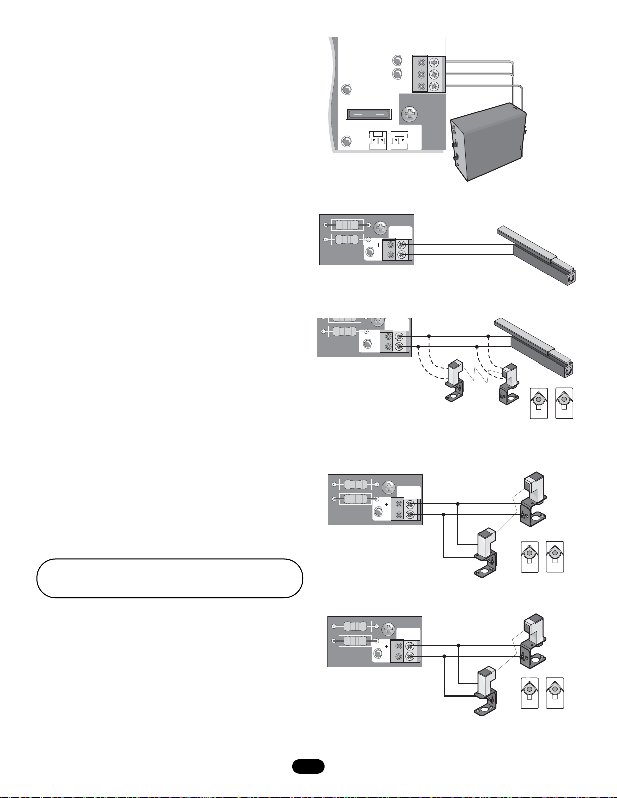
PHOTO/EDGE INPUTS (P6-7-8 and 9) (see page 13)
Terminal P 6 – C lose Edge
This input will reverse a closing gate. It will disable the Timer-toClose if that feature has been enabled. Activating this input while
the gate is opening will have no effect.
Terminal P 8 – O pen Edge or Ph oto Eye
If an Open Edge device or a Retro-Reflective Photo Eye has been
connected to Terminal P8, then this input will reverse an opening
gate for 2 seconds then stop. Activating this input with an Open
Edge device or a Retro-Reflective Photo Eye connected to
Terminal P 8 w hile the ga te is closi ng will have n o effect.
If a Chamberlain Pulsing Photo Eye has been connected to
Terminal P 8, then this i nput will p ause an open ing gate un til the
obstruction has been removed. Upon removing the obstruction,
the gate will continue to open. Activating this input with a
Chamberlain Pulsing Photo Eye connected to Terminal P8 while
the gate is closing will have no effect.
Terminal P 7 – O pen Photo Ey e
This input will pause an opening gate until the obstruction has
been removed. Upon removing the obstruction, the gate will
continue to open. Activating this input while the gate is closing
will have no effect.
Terminal P 9 – C lose Phot o E ye
This input will reverse a closing gate to the open limit. Activating
this input while the gate is opening will have no effect. The Timerto-Close will not reactivate at the open limit.
NOTE: Make sure the positive (+) and negative (-) wires are
wired correctly.
LOOP INPUTS (P11) (see page 13)
Shadow Loop Input Terminal and Common
This input protects cars by preventing the gate from moving off
of the open or close limit when the shadow loop input is active.
Interrupt Loop Input Terminal and Common
This input functions to reverse a closing gate to the open limit.
Latching this input will reset the timer to close.
CLOSE
EDGE
OPEN EDGE
PHOTO
or
771E
OPEN
PHOTO
or
771E
CLOSE
PHOTO
or
771E
See page 15 for Dip-Switch settings.
Unused safety inputs may require a wire bridge (JUMPER)
F1 20A 32V
FUSE
OPEN
CHGR
OVLD
SHADOW
INTERRUPT
BATT 1BATT 2
COM
LOOP
INPUTS
SHADOW LOOP
INTERRUPT LOOP
COMMON LOOP
PR
ES
E
NCE
RE
L
AY
Sarasota
2
625X
SEN
S
625 X
FRE
FRE
Q
Q
MADE IN USA
Page 13

13
MAGLOCK/ALARM/FLASHING LIGHT
Flashing Light
(optional)
Siren
(optional)
Maglock
When enabled, the maglock output is activated (energized) while the gate
is in motion.
E-Lock
(optional)
Maglock
(optional)
ALARM
MAGLOCK
GATE 1
ACCESSORY
POWER
GATE 2
J4
P2
U3
D1
D6
TIMER
RUNNING
TIMER TO
D4
D2
P1
CLOSE
F7
C13
J18
U4
J19
10A 32V
R9
R196
K6
J1
K5
L1
1
R2
LEARN
SINGLE
XMITTER
R1
2
F3
D1
Ø
K2
DIAGNOSTIC
SET
K1
Q9
OPEN
LIMIT
Ø
Ø
1
R1
R1
ØØ
F4
K4
K3
Q22
ACCESSORY
OVLD
F5
D21
D8
D22
MOV1
JMPR2
DB1
10A 32V
MOV2
NO
C
NO
C
NC
Z1
BRN
GRN
WHT
YEL
BLU
RED
Z12
24V
BRN
GRN
WHT
YEL
BLU
RED
D15
C2R4
24 VAC/
SOLAR
INPUT
Ø
14GPØ89ØE
Ø
14LGØ89ØE
Ø
14SKØ89ØE
O
N
1 2 3 4 5
OFF
ON
OFF
NO
NO
SAVE
ON
MAGLOCK
DUAL
MODE
EDGE
NC
PHOTO
NC
S1
GATE 1
SET
LEARN
CLOSE
LIMITS
LIMIT
GATE 2
BIPART
DELAY
FORCE
MIN MAX OFF MAX OFF MAX
R35
D9
C12
D27
Z3
Z4
C11
R9
C64
JMPR1
U2
F6
F2
SINGLE
BUTTON
C4
R2
Ø
7
Ø
Z2
R227
R224
SINGLE BUTTON
CHGR
OVLD
F1 20A 32V
FUSE
OPEN
R223
Z22
R92
R91
R94
R93
COM
OVLD
OPEN
RESET
STOP
POWER
SHADOW
INTERRUPT
24V
OVLD
BATT 1BATT 2
COM
COM
COM
CLOSE
EDGE
OPEN EDGE/
PHOTO
OPEN
PHOTO
CLOSE
PHOTO
SWITCHED
ACCESSORY
POWER
CONTROL
INPUTS
LOOP
INPUTS
Z9
Z8
Accessory
Power
Auxillary Output Power for Optional Devices
(2) +24VDC Outputs (P13 and P12) have
been provided for optional devices
Maximum 300mA combined output
The switched output should be used only if the gate is
powered by a solar panel to reduce the energy consumption
during stand by.
Page 14

FORCE
GATE 2
SET
OPEN
LIMIT
SET
CLOSE
LIMIT
LEARN
LIMITS
DIAGNOSTIC
GATE 1
14
TIMER TO CLOSE ENABLE
Set the TIMER TO CLOSE to
desired setting. The range is 0 to
180 seconds, 0 seconds is OFF.
FORCE CONTROL
Set the sensitivity such that the unit will
complete a full cycle of gate travel but will
reverse off an obstruction without applying
an unreasonable amount of force.
BIP
ART DELAY
Set the BIPART DELAY to desired
setting. The range is 0 to 8
seconds, 0 seconds is OFF.
FORCE AND TIMER TO CLOSE
PROGRAM LIMITS
1. Turn BiPart switch to desired setting. Set to “Off” for single
gate applications.
2. Press the “LEARN LIMITS” button.
3. The “SET OPEN LIMIT” LED will blink.
4. Use any of the “Gate 1” buttons to move Gate 1 to the
desired open position. Repeat if Gate 2 is present using “Gate
2” buttons.
5. Press the “LEARN LIMITS” button to set the Open Limit for
gate(s).
6. The “SET OPEN LIMIT” LED will turn off. The “SET CLOSE
LIMIT” LED will blink.
7. Use the “Gate 1” buttons to move Gate 1 to the desired close
position. Repeat if Gate 2 is present using “Gate 2” buttons.
8. Press the “LEARN LIMITS” button to set the close limit for
gate(s).
9. The “SET CLOSE LIMIT” LED will turn off. The limits are set.
10 Using programmed remote or single button input (SBC) run
the gate(s) from the close limit to the open limit. After
reaching the open limit, run the gate(s) to the close limit.
This will learn the force in the open and close direction.
11. If the learned force is not high enough, manually
adjust the force control as described above.
NOTE: Any following SBC or Remote inputs will move the gate
.
The “Save” Dip switch must be set to OFF to allow programming.
After completion set the “Save” switch back to on.
INSTALL ALL EQUIPMENT IN COMPLIANCE WITH EN60335-2-103, EN13241-1.
MIN MAX OFF MAX OFF MAX
ALARM
MAGLOCK
GATE 1
ACCESSORY
POWER
GATE 2
NO
C
NO
C
NC
Z1
BRN
GRN
WHT
YEL
BLU
RED
BRN
GRN
WHT
YEL
BLU
RED
C2R4
J4
K6
K5
1
R2
XMITTER
10A 32V
Z12
24V
D15
R196
24 VAC/
SOLAR
INPUT
R1
2
F3
Ø
D1
K2
K1
Q9
OPEN
10A 32V
LIMIT
Ø
1
R1
R1
ØØ
F4
K4
K3
Q22
R9
Ø
MOV2
J19
J1
L1
OFF
OFF
LEARN
SINGLE
NO
NO
S1
DIAGNOSTIC
SET
FORCE
ACCESSORY
OVLD
MIN MAX OFF MAX OFF MAX
F5
D21
D8
C12
D22
C11
MOV1
C64
JMPR2
U2
DB1
O
N
1 2 3 4 5
SET
CLOSE
LIMIT
P2
Ø
14GPØ89ØE
Ø
14LGØ89ØE
Ø
14SKØ89ØE
ON
SAVE
ON
MAGLOCK
DUAL
MODE
NC
EDGE
NC
PHOTO
GATE 1
LEARN
LIMITS
TIMER
GATE 2
RUNNING
BIPART
TIMER TO
DELAY
CLOSE
R35
D9
D27
Z3
F7
Z4
U3
D4
R9
D1
JMPR1
D2
D6
R223
P1
R2
Ø
7
Z2
Ø
R227
J18
R224
U4
SINGLE
BUTTON
SINGLE BUTTON
C13
C4
CHGR
OVLD
F6
F2
F1 2
0
A 32V
FUSE
OPEN
Z22
R92
R91
R94
R93
OVLD
RESET
POWER
SHADOW
INTERRUPT
CLOSE
EDGE
OPEN EDGE/
PHOTO
Z9
OPEN
PHOTO
Z8
CLOSE
PHOTO
24V
SWITCHED
ACCESSORY
COM
OVLD
POWER
CONTROL
INPUTS
OPEN
STOP
COM
COM
LOOP
INPUTS
COM
BATT 1BATT 2
Page 15

COM
OVLD
S1
SAVE
MAGLOCK
MODE
EDGE
PHOTO
OFF
OFF
SINGLE
NO
NO
ON
ON
DUAL
NC
NC
1 2 3 4 5
O
N
DIP SWITCH SETTINGS
SAVE SWITCH S1-1
This switch (S1-1) is used to save the settings for
switches 2 thru 5 and the limits of the gate.
NOTE: When setting switches S2-5 the save switch
must be in the off position prior to setting or changing
switches for the change to be saved.
MAG DELAY ENABLE
This switch (S1-2) enables the Mag Lock/E-Lock feature.
On an open command there will be a .5 second delay
before the motor starts, to allow the Mag Lock/E-Lock to
release.
MODE DUAL/SINGLE
This switch (S1-3) sets the mode as Dual or Single
(See Programming section for mode).
SAFETY INPUTS
Swing gates allow four safety inputs. A DIP switch is
required for determining between N/O and N/C edges and
N/O and N/C eyes.
EDGE INPUT (SAFETY EDGE)
Set switch (S1-4) to the following settings:
N/O Edge (Active Close) = 8.2K, 10K Edge, N/O dry
contact edge
N/C Edge (Active Open) = N/C dry contact edge
NOTE: Monitored Edges should be set in the N/O
position, as the activation condition is shorting the
terminals. Unused inputs in N/C mode require a wire
bridge (JUMPER).
PHOTO-EYE INPUT (PHOTOCELL)
This switch (S1-5) differentiates between N/O and N/C
dry contact photoelectric eye inputs.
NOTE: Pulsing Chamberlain photoelectric eyes will
automatically learn in N/C mode. Unused inputs in N/C
mode require a wire bridge (JUMPER).
15
ALARM
MAGLOCK
GATE 1
ACCESSORY
POWER
P2
GATE 1
LEARN
LIMITS
GATE 2
SAVE
MAGLOCK
MODE
EDGE
PHOTO
TIMER
RUNNING
P1
J19
NO
C
NO
C
NC
Z1
BRN
GRN
WHT
YEL
BLU
RED
K6
K5
L1
S8
1
R2
LEARN
XMITTER
10A 32V
Z12
R1
2
F3
Ø
D1
K2
SET
K1
Q9
OPEN
Ø
R9
LIMIT
J1
OFF
OFF
SINGLE
NO
NO
DIAGNOSTIC
S1
O
N
1 2 3 4 5
SET
CLOSE
LIMIT
Ø
Ø
Ø
ON
ON
DUAL
NC
NC
14GPØ89ØE
14LGØ89ØE
14SKØ89ØE
R223
Ø
7
R2
Z2
Ø
R227
J18
R224
Z22
U4
R92
R91
R94
R93
24V
OVLD
CLOSE
EDGE
OPEN EDGE/
PHOTO
Z9
OPEN
PHOTO
Z8
CLOSE
PHOTO
SWITCHED
ACCESSORY
POWER
MAG DELAY
SAVE
OFF
OFF
OFF
OFF
O
N
1 2 3 4 5
O
N
1 2 3 4 5
O
N
1 2 3 4 5
SAVE
ON
O
N
1 2 3 4 5
ON
MAG DELAY
ON
OFF
OFF
SINGLE
NO
NO
OFF
OFF
SINGLE
EDGE NO
OFF
OFF
SINGLE
PHOTOEYE NO
O
N
1 2 3 4 5
N
N
O
1 2 3 4 5
O
1 2 3 4 5
O
N
1 2 3 4 5
ON
ON
DUAL
NC
ON
ON
DUAL
NC
ON
ON
DUAL
NC
NC
Page 16

16
External entrapment
protection systems
●
Check for proper operation
Gate warning signs
●
Make sure they are present
Manual disconnect
●
Check and operate
Gate
●
Inspect for wear or damage
Accessories
●
Check all for proper operation
Electrical
●
Inspect all wire connections
Frame bolts
●
Check for tightness
Total unit
●
Inspect for wear or damage
6 MONTHS
MONTHLY
3 MONTHS
WEEKLY
12 MONTHS
6 MONTHS
TASK
CHECK AT LEAST ONCE EVERY
Complete Check Out
NOTES:
1. Disconnect power before servicing.
2. Severe or high cycle usage will require more frequent maintenance checks.
3. Inspection and service should always be performed anytime a malfunction is observed or suspected.
4. When servicing, please do some “house cleaning” of the operator and the area around the operator. Pick up any debris in the area.
Clean the operator as needed.
5. It is suggested that while at the site voltage readings be taken at the operator. Using a Digital Voltmeter, verify that the incoming
voltage to the operator it is within ten percent of the operators rating.
DESCRIPTION
To r educe the r isk of SEVER E INJURY or DE ATH:
• Disconnect ALL power BEFORE performing ANY
maintenance.
• ALL maintenance MUST be performed by a LiftMaster
professional.
IMPORTANT SAFETY INSTRUCTIONS
To reduce the risk of SEVERE INJURY or DEATH:
1. READ AND FOLLOW ALL INSTRUCTIONS.
2. NEVER let children operate or play with gate controls.
Keep the remote control away from children.
3. ALWAYS keep people and objects away from the gate.
NO ONE SHOULD CROSS THE PATH OF THE MOVING
GATE.
4. Test the gate operator monthly. The gate MUST reverse
on contact with a rigid object or stop when an object
activates the non-contact sensors. After adjusting the
force or the limit of travel, retest the gate operator.
Failure to adjust and retest the gate operator properly
can increase the risk of INJURY or DEATH.
5. Use the emergency release ONLY when the gate is not
moving.
6. KEEP GATES PROPERLY MAINTAINED. Read the
owner’s manual. Have a qualified service person make
repairs to gate hardware.
7. The entrance is for vehicles ONLY. Pedestrians MUST
use separate entrance.
8.
SAVE THESE INSTRUCTIONS.
OPERATION and MAINTENANCE
MAINTENANCE
MONTH
DAILY
●
COMMERCIAL USE 50+ CYCLES/DAY (350+ PER WEEK
RESIDENTIAL USE 1-50 CYCLES/DAY (350 PER WEEK)
Page 17

17
WIRING DIAGRAM
To p rotect ag ainst fir e and elect rocuti on:
• DISCONNECT power BEFORE installing or servicing
operator.
• Replace ONLY with fuse of same type and rating.
D6
JMPR2
DB1
Siren
T
(optional)
Flashing Light
E-Lock
(optional)
Maglock
(optional)
GATE 1
(Opens First)
GATE 2
GROUND
(Optional)
GREEN/YELLOW
150VA
TORROID
TRANSFORMER
BRN
GRN
WHT
YE L
BLU
RED
BRN
GRN
WHT
YE L
BLU
RED
ALARM
MAGLOCK
GATE 1
ACCESSORY
POWER
GATE 2
J4
P2
BIPART
DELAY
SAVE
MAGLOCK
MODE
EDGE
PHOTO
U3
D1
D6
TIMER
RUNNING
D4
TIMER TO
D2
CLOSE
F7
P1
C13
J19
D15
24 VAC/
SOLAR
INPUT
YELLOW
10A 32V
R196
K6
J1
K5
L1
1
R2
LEARN
XMITTER
R1
2
F3
ÿ
D1
K2
SET
K1
Q9
OPEN
10A 32V
LIMIT
R1
ÿ
1
R1
ÿÿ
F4
ACCESSORY
OVLD
K4
F5
D21
K3
D8
D22
Q22
MOV1
JMPR2
DB1
R9
ÿ
MOV2
O
N
1 2 3 4 5
OFF
ON
OFF
SINGLE
DIAGNOSTIC
ON
DUAL
NO
NC
NO
NC
S1
GATE 1
SET
LEARN
CLOSE
LIMITS
LIMIT
GATE 2
FORCE
MIN MAX OFF MAX OFF MAX
R35
D9
C12
D27
Z3
Z4
C11
R9
C64
JMPR1
U2
BLUE
SECONDARY
NO
C
NO
C
NC
Z1
BRN
GRN
WHT
YEL
BLU
RED
Z12
24V
BRN
GRN
WHT
YEL
BLU
RED
C2R4
J18
U4
F6
F2
BLACK
C4
SINGLE
BUTTON
ÿ
7
R2
R224
SINGLE BUTTON
F1 20A 32V
FUSE
OPEN
CHGR
OVLD
RED
Z2
ÿ
R227
R223
Z22
R92
R91
R94
R93
OVLD
RESET
POWER
SHADOW
INTERRUPT
CLOSE
EDGE
OPEN EDGE/
PHOTO
Z9
OPEN
PHOTO
Z8
CLOSE
PHOTO
24V
SWITCHED
ACCESSORY
COM
OVLD
POWER
CONTROL
INPUTS
OPEN
STOP
COM
COM
LOOP
INPUTS
COM
BATT 1BATT 2
BLACK
OR OR
EDGE EDGE EDGE
OR OR
EDGE
EDGE
PULSING PHOTO
OR OR
PHOTO
PHOTO
PULSING PHOTO
OR OR
PHOTO
PHOTO
24VDC OUTPUT
SWITCHED OFF
IN LOW POWER MODE
OPEN (EXIT LOOP)
SINGLE BUTTON
RESET
STOP
COMMON (+24VDC)
COMMON (+24VDC)
SHADOW LOOP
INTERRUPT LOOP
COMMON (+24VDC)
RED
EDGE
PULSING PHO
OR
GREEN/YELLOW
CHARGE TRANSFORMER
PRIMARY
Page 18

18
OPERATOR IS DEAD
When power is supplied to
the control board, no LED
turns ON.
OPERATOR DOES NOT RUN
Unit does not respond to a
Radio command.
OPERATOR DOES NOT RUN
Unit does not respond to
SBC command.
MOTOR DOES NOT RUN
Relays ‘click’ when Radio
or SBC signal is given, but
the operator does not
move.
GATE STOPS AND
REVERSES RIGHT AFTER
IT STARTS MOVING
GATE STOPS RUNNING
RIGHT AFTER IT STARTS
MOVING (BATTERY RUN)
GATE OPENS BUT DOES
NOT CLOSE
GATE LOSES LIMITS
1) Battery fuse is blown. ➤ Replace battery fuse. Use only 20A, ATC style fuse.
2) Battery or Run Transformer
➤ Check battery and transformer connections.
connection is loose.
3) Dead battery.
➤ Measure voltage across battery > 23V.
4) Bad control board.
➤ Replace control board.
1) Low battery.
➤ Measure voltage across battery >23V.
2) SBC button connection loose.
➤ Check SBC and COM connections to ensure they are secure.
3) STOP button connection loose.
➤ Check STOP button connections (STOP and COM) to make sure they
STOP LED is OFF. are secure.
4) Obstruction is blocking the photoelectric
➤ Check gate area to ensure photoelectric eyes are not blocked.
eyes in the direction of movement.
5) The safety edge is damaged
➤ Check gate area to ensure safety edge is not resting on an obstruction.
or on an obstruction.
➤ Check safety edge wiring and connections.
6) Interrupt loop is obstructed.
➤ Check gate area to ensure path is unobstructed.
7) Bad control board.
➤ Replace control board.
8) Motor fuse is blown.
➤ Replace motor fuse. Use only 10A, ATC style fuse.
9)Indicator light blinks.
➤ Reset system by achieving the Stop/Reset with a wire bridge momentarily.
10)Release lever opened.
➤ Reconnect arm.
1) Bad motor. ➤ Replace motor.
2) Cable wiring between control and
➤ Fix wiring or connect arm.
operator arm disconnected or loose.
3) Bad control board.
➤ Replace control board.
4) Batteries not connected.
➤ Connect batteries.
1) A fault has occurred. ➤ Check gate for obstructions.
2) Force set too low.
➤ Adjust FORCE setting until gate completes a full open/close cycle
without reversing. The force setting may need to be adjusted in cold
weather, as the gate will not move as freely.
1) Battery voltage low or near low ➤ Charge batteries. If problem persists, they may be near the end of their
voltage cut-off. LED blinks 11x. life. Replace batteries.
NOTE: Replace both batteries at the same time.
2) A fault has occurred. ➤ Check gate for obstructions.
➤ Check motor terminals.
1) An input is continuously activated. ➤ Verify that all inputs are functioning properly.
2) Entry system output is connected to
➤ Verify Entry system connections and operation.
the Open input, and is “stuck” opening.
➤ Disconnect devices or Led if gate closes. Reconnect devices after one
by one.
FAULT POSSIBLE CAUSE FIX
TROUBLESHOOTING
1) After a day the programming is lost or ➤ Make sure the “SAVE” Dip-switch is back to “ON” after programming.
different.
1)Low battery.
➤ Measure voltage across battery > 23V.
2)Radio (remote) not programmed.
➤ See Programming Remote section for programming instructions.
3)STOP button connection loose.
➤ Check STOP button connections (STOP and COM) to make sure they
STOP LED is OFF. are secure.
4)There is an obstruction blocking
➤ Check gate area to ensure photoelectric eyes are not blocked.
photoelectric eyes in direction
of movement.
5)Safety edge is damaged or on an
➤ Check gate area to ensure safety edge is not resting on an obstruction.
obstruction. Check safety edge wiring and connections.
6)Interrupt loop is obstructed.
➤ Check gate area to ensure path is unobstructed.
7)Bad control board.
➤ Replace control board.
8)Motor fuse is blown.
➤ Replace motor fuse. Use only 10A, ATC style fuse.
9)Release lever opened.
➤ Reconnect arm.
Page 19

19
GATE RUNS TOO SLOW
GATE DOES NOT CLOSE
AUTOMATICALLY
GATE WON’T STAY OPEN
WHEN USING FIRE INPUT
Fire Input switch should
be a constant contact
key switch connected to
Open Loop input
(Open only).
INTERRUPT LOOP DOES
NOT ACT PROPERLY
EXIT LOOP (FREE EXIT)
DOES NOT OPEN GATE
MAGLOCK DOES NOT
WORK
Maglock does not hold
gates locked
STATUS INDICATOR LED
BLINKS
# OF BLINKS (1-11) AND
THEIR MEANING
PHOTO LED’S ON BOARD
INDICATE PROBLEM BUT
PHOTOCELLS AND WIRING
ARE OK
1) Open and Close Limits are set too ➤ If the Open and Close Limits are set within the ramp down distance of
close together. each other, the gate will run at slow speed all the time.
2) The gate is starting within the ramp
➤ Gate will run slow to limits if motion is started within the ramp-down
down distance from the Open or distance from the limit.
Close Limit.
1) Verify that the TTC is turned OFF. ➤ Verify that the TTC (Timer To Close) is ON and set.
2) Gate opened by an obstruction reversal.
➤ Check gate area to ensure path is unobstructed.
3) The Interrupt Loop is obstructed.
4) Obstructed close photoelectric eye or edge.
5) The Open input is "stuck".
➤ Check the Open Loop area to ensure all obstructions are removed. If an
external opening device or entry or entry system is attached, check for
proper operation of that system.
1) Fire Input switch is a momentary ➤ Make sure the Fire Input switch is constant contact. If it is not, replace
contact. with a constant contact switch.
1) Bad loop sensor or loop detector. ➤ Replace loop sensor or loop detector.
2) Bad connection between loop sensor,
➤ Check connections to make sure they are secure.
loop detector, and the control board.
1) Bad loop sensor or detector. ➤ Replace loop sensor or loop detector.
2) Bad connection between the loop
➤ Check connections to make sure they are secure.
sensor, loop detector, and the
control board.
3) The Shadow Loop is obstructed.
➤ Check the gate area to make sure all obstructions are removed.
4) An Open photoelectric eye or safety
➤ Check the gate area to make sure all obstructions are removed.
edge is obstructed.
1) Bad connection between the Maglock, ➤ Check connections between the Maglock, its power supply, and
its power supply, and the control board. the control board to make sure they are secure.
2) Bad Maglock or Maglock power supply.
➤ Replace Maglock or Maglock power supply.
3) Large gap between gates.
➤ Reduce the gap between the gates.
4) Bad control board.
➤ Replace the control board.
FAULT POSSIBLE CAUSE FIX
TROUBLESHOOTING
1) No stop switch connected 6) Force reversal 11) Battery low or bad
2) Gate 1 arm disengaged 7) Processor Reset
3) Gate 2 arm disengaged 8) ROM check failed
4) Both gate arms disengaged 9) RAM check failed
5) RPM reversal 10) EEPROM check failed
1) Dip switch setting incorrect NO/NC ➤ Set Dip switch correctly
for Photo/Edge.
➤ Set program “Save” switch to OFF
2) Photocell still bad or misaligned
➤ Check LED’s of Photocells if LED is constant.
➤ Detach Photocells and jumper output “Dip to NC” to see if it works.
➤ Switch to OFF or cycle switch with a pause (2-3 seconds)
Page 20

Refer to the parts lists below for replacement parts available for your operator. If optional modifications and/or accessories are included
with your operator, certain components may be added or removed from these lists.
E-BOX ASSEMBLY
ITEM PART # DESCRIPTION QTY
1K79-12815Control Board 1
2K75-15480Control Box & Cover
with Gasket 1
3K75-30764Control Board Bracket1
4 K74-19499 Antenna 1
5600190Battery 2
6K74-30763Charge Transformer1
K21-30749 Run Transformer 1
Not Shown K74-30941 ATC Fuse Kit Includes
20 Amp (1), 10 Amp (2)
REPAIR PARTS
WHEN ORDERING REPAIR PARTS, ALWAYS GIVE THE
FOLLOWING INFORMATION:
• PART NUMBER
• PART NAME
• MODEL NUMBER
ADDRESS ORDERS TO:
Email: info@chamberlain.com
www.liftmaster.com
HOW TO ORDER REPAIR PARTS
INSTALLATION AND SERVICE INFORMATION
IS AS NEAR AS YOUR TELEPHONE SIMPLY DIAL:
Int. Service (+49) 6838/907 172
für Service 06838/907 172
for service (+44) 0845 602 4285
pour service 03 87 95 39 28
voor service 020 684 7978
INT
D
GB
F
NL
© 2005, Chamberlain GmbH, Inc
01-32640B All Rights Reserved
2
3
1
6
5
4
 Loading...