

Page 1

T
M
TM
TM
TM
TM
TM
Chamberlain GmbH
Alfred-Nobel-Str. 4
D-66793 Saarwellingen
www.chamberlain.de
e-mail: info@chamberlain.de
ELECTRONIC BARRIER WITH AUTOMATIC FUNCTION
TM
TM
TM
Page 2
2/40
Notes
PLEASE START BY READING THESE IMPORTANT SAFETY RULES • SAVE THESE INSTRUCTIONS
This safety alert symbol means "Caution" - failure to comply with such an instruction involves risk of personal injury or damage to property. Please read these warnings carefully.
This barrier is designed and tested to offer appropriately safe service provided it is installed and operated
in strict accordance with the following safety rules.
Incorrect installation and/or failure to comply with the following instructions may result in serious personal
injury or property damage.
Installation and wiring must be in compliance
with your local building and electrical installation codes. Power cables must only be connected to a properly earthed supply.
Any entrapment possibility by the moving wing
between wing & walls must be secured with
safety edges or IR-sensors.
Disconnect electric power to the system
before making repairs or removing covers.
A disconnecting device must be provided in the permanently-wired installation
to guarantee all-pole disconnection by
means of a switch (at least 3mm contact
gap) or by a separate fuse.
At least one Warning Sign for every traffic
direction is to be put up in the barrier
environment.
Make sure that people who install, maintain or operate
the barrier and/or the control board are
qualified and follow these instructions.
Keep these instructions in a safe place
so that you can refer to them quickly
when you need to.
Some installation steps require a second
person.
After the installation a final test of the full function of the system and the full function of the
safety devices must be done.
The full protection against potential
squeeze or entrapment must work direct
when the drive arms are installed.
Pedestrians must not pass the barrier and
must have save access next to the barrier.
IMPORTANT FITTING AND OPERATING INSTRUCTIONS
WARNING / ATTENTION
Page 3

3/40
Notes
Contents
1 Important information
1.1 Use as prescribed
1.1.1 Designated setting
1.2 Influence of wind
1.3 Safety
1.3.1 General safety advice
1.3.2 Minimizing the risks
1.3.3 Safety for pedestrians
1.3.4 Explanation of warning signs used in the manual
1.3.5 Installation and maintenance
1.4 Service
1.4.1 Wearout parts and maintenance
1.5 Technical changes
1.6 Manual as part of the product
2 Guarantee
3 Overview
3.1 Overview of models
3.2 Main accessories
3.3 Additional accessories
4 Installation examples
4.1 Example 1
4.2 Example 2
4.3 Example 3
4.4 Example 4
4.5 Example 5
5 Operation description
5.1 Operation of barrier
5.2 Description of parts
5.3 Operation of barrier (straight pole)
5.4 Operation of barrier (90° articulated pole)
5.5 Operation of barrier (180° folding pole)
5.6 Operation of barrier (lattice/fence)
5.7 Operation of motor
5.8 Operation of spring (balancing spring)
5.9 Operation of limit switches
6 Installation
6.1 Foundation construction: barrier
6.2 Foundation construction: tip support post (support)
6.3 Contact loops (induction loops) - description
6.4 Installation of induction loops – general
6.5 Installation of induction loops – procedure
6.6 Installation of operation switches
6.7 Usage of photocells
7 Mounting
7.1 Service door
7.2 Removing the hood
7.3 Release (manual operation)
7.4 Mounting the barrier (casing)
7.5 Mounting the tip support post (support)
7.6 Mounting the barrier pole (straight)
7.7 Adjusting the length
7.8 Mounting the barrier pole (90° articulated)
Page 4

4/40
Notes
7.8.1 Mounting the articulated-guide
7.8.2 Adjusting the length
7.9 Fixation and setting of push rod for articulated barrier
7.10 Construction barrier left / right and conversion
8 Spring balance
8.1 Testing
8.2 Spring setting
8.3 Correcting spring settings
8.4 Removing the spring
9 Electric connection
9.1 Connection to supply voltage
9.2 Earthing
9.3 Main switch
9.4 Handling in case off power failure
9.5 Electrical protection of unit
10 Control unit
10.1 Functions of control unit
10.2 Control unit’s modes of operation
10.3 Operation via radio
10.4 Connecting control unit
10.5 Installation description of control unit
10.5.1 Description of screw terminals
10.5.2 Description of socket connectors
10.5.3 Description of switches
10.5.4 Description of signal LED’s
11 Adjusting the barrier
11.1 Adjustment of limit switches
11.2 Correcting the limit switch adjustments
11.3 Adjusting length of connecting arm between motor and barrier axle
12 Completion (finalizing installation)
13 Trouble shooting and FAQ’s
13.1 Barrier does not work (no movement)
13.2 Does not open
13.3 Does not close
13.4 Does not open / close, incomplete movement or is slow
13.5 Barrier is not quite vertical / horizontal
13.6 Other
14 Technical Data
14.1 General
14.2 Dimensions of articulated barrier pole 90°
14.3 Articulated and folding barrier pole 180°
14.4 Lattice barrier pole
14.5 Technical support
14.6 Spare parts
15 Test certificate and handover
Page 5

5/40
Notes
1 Important information
1.1 Use as prescribed
Our herein described barrier models and accessories are suitable for locking and opening
entries and exits to parking lots, access roads and entries for motor vehicles and motorbikes.
A different use or a use beyond the here described ones is not in line with the prescribed use;
especially not permissible for pedestrian traffic.
The control is only designed for operation with these barriers. Conversions or changes which are
not described herein are not permitted and need to be approved of in writing in each individual
incidence.
In case of improper use neither the manufacturer nor the distributor may be held liable for any
resulting direct injuries and/or damages or consequential damages.
1.1.1 Designated setting
The barrier may be mounted outdoors or indoors. All parts of the barrier are sufficiently protected
against corrosion in order to guarantee a long life span. The barrier base must be protected
against moisture with the aid of a pedestal. An escape (outlet) for rain must also be provided for.
The permitted temperature ranges are to be considered.
Mounting is not permissible in explosion-prone spaces or in spaces where hazardous and
combustible gases are present.
1.2 Influence of wind
The standard barrier pole fastening can withstand a maximum wind velocity of 10 (heavy storm)
or 28,5m/s resp. 102 km/h. With barrier pole length of more than 4m it must be taken into
consideration what damage can be caused in the case of barrier fracture of a vertically positioned
barrier pole.
Page 6
1.3 Safety
1.3.1 General safety advice
This barrier is constructed and tested in order to guarantee sufficient safety when installed and
when used according to the following safety regulations.
The products have left our house free of faults. Still there can be risks involved when mounting or
during later operation, if the product has been installed or used improperly. Keep manual within
reach, so it can be consulted by the owner of the unit at any time.
The manufacturer cannot foresee each critical point which can be caused by the installed product.
The operator of the unit and the installer have to ensure that no risks may result for people or
objects. If parts of the unit are damaged (e.g. barrier pole broken) the unit must be taken out of
service. Only authorized and skilled professionals may make the necessary repairs. A complete
security check including proper documentation is necessary after the repair work.
1.3.2 Minimizing the risks
The installer of the unit has to take care to minimize possible remaining risks according to the
latest state of engineering.
Example 1: Put up sufficient signal panels, warning signs or surrounding construction in order that
pedestrians are adequately warned and do not cross the barrier unit’s path.
Example 2: Construct entry width for vehicles in a way so wider, longer and higher vehicles may fit
through entry without problems, i.e. without damaging the unit. Install clearly visible warning signs.
1.3.3 Safety for pedestrians
The utmost care must be taken to ensure the safety of pedestrians.
This means that this instruction manual must be followed carefully.
Also, country-specific directives and regulations in order to
avoid accidents must be considered and adhered to. A barrier unit is
not safe for pedestrians and/or cyclists and must not be operated by
either resp. be operateable by either. The installer or operator must
ensure suitable measures and separate pedestrian and vehicle traffic.
It is necessary to put up a sufficient number of warning signs and to
ensure security by means of construction (walls/fences etc.).
The pedestrian path must be outside the barrier path. The opening and
closing movements of the barrier must be carefully watched and sur
veyed. If no surveillance or monitoring is possible then operation is not
permitted.
1.3.4 Explanation of warning signs used in the manual
Possible risks and notes are indicated in the following way in this manual and operation guide:
WARNUNG / ACHTUNG:
This safety alert symbols mean "Caution " - failure to comply with such an instruction involves risk of
personal injury or damage to property. Please read these warnings carefully. Incorrect installation
and/or failure to comply with the following instructions may result in serious personal injury or property
damage.
6/40
Notes
Page 7

7/40
Notes
1.3.5 Installation and maintenance
• All units must be connected according to our instructions.
• Before opening the control unit the power supply must be disconnected.
• In case of maintenance/repair work all command devices (radio, switches, push buttons, loops)
must be deactivated, so that the barrier does not move uncontrollably.
• There is a risk of jamming and getting caught due to moving parts when the barrier casing is
open (door/lid). Utmost caution should be taken with electrical power, tension springs and moving
parts.
• Minimum distance: 500mm between barrier pole tip and a solid obstacle.
• After installation is complete check to make sure that the mechanism is properly set and that the
drive, security system and emergency release function correctly.
• Remove all additional accessories out of the reach of children. Do not allow children to operate
push buttons or remote controls. Serious injury may be the result of a closing barrier.
• Upon start-up all necessary safety devices must be installed, working and tested. The locally
effective regulations must be adhered to.
• In case of maintenance, cleaning or service the roadway must be blocked from traffic.
• All command devices must be installed with direct visual contact to the barrier.
• During the movement of the barrier no people or vehicles may be directly under the barrier.
• When planning, mounting and operating the barrier care must be given towards cables and other
objects in the swivel axis of the barrier pole.
• The area for and around the mounting spot of the barrier must have a solid floor space with
heavy load capacity and must be free of obstacles.
• Start-up without proper anchorage of barrier unit to floor space is not permitted.
• The mounting/disassembly of the barrier pole is only permitted in calm wind.
• The mounting/disassembly of the barrier requires two people.
• With barrier pole length exceeding 4.5m we recommend a support or tip support post. If barrier
pole is 6m or longer this is a regulation and must be adhered to.
• The surface temperature of the motor can exceed 90°C. Potential danger of burning.
• In case of shut-down or in times when the unit is not checked, the barrier pole must remain
closed. If the barrier is to remain open, the barrier pole must be removed completely.
Page 8

8/40
Notes
1.4 Service
Barrier units are not maintenance free and therefore need regular inspection. Hereby the number
and extent of the inspections depend on the frequency of use (number of cycles) and where the
unit is placed and less on the time span since the previous inspection. The operator must keep
an inspection record of all risks which describes and confirms the extent of the inspection.
An inspection record should contain:
• V
isual inspection: apparent deficiencies, damages through vehicles, environmental influences
or vandalism. Visual inspection of safety installations and signposting. Frequency: depends on
where unit is placed and vehicle frequency: daily ? monthly to be carried out by a qualified /
experienced person (janitor, technician)
• Inspection / service:
in addition to visual inspection. Complete inspection of unit regarding
mechanical signs of wear. If necessary exchange parts and repair.
• In order to make use of the guarantee it is necessary to conclude a maintenance contract with
the operator of the unit and to have regular maintenance / inspections of unit carried out.
Estimated cycles per annum:
Pole length ¼ yearly maintenance ½ yearly maintenance Yearly maintenance
Up to 3m 1 sec. 250 000 125 000 75 000
Up to 4.5m 3 sec. 200 000 100 000 50 000
Up to 6m 6 sec. 100 000 50 000 25 000
6m -8m 6 sec. 25.000 15.000 5000
1.4.1 Wearout parts and maintenance
• Balance spring 750 000 = exchange
• Spring guide 250 000 = lubrication
• Drive mechanism 250 000 = inspection of lubrication
• Ball bearing rotary arms 250 000 = lubrication
• Screws every inspection = check (tighten)
• Control every inspection = visual check (leak test)
• Cables and connections every inspection = visual check
• Articulated poles every inspection = visual check
• Limit stops every inspection = visual check
• Limit switch Photocells every inspection = visual check (soiling)
• Stability every inspection = check
• Soiling every inspection = visual check
• Corrosion of casing every inspection = visual check
• Barrier pole every inspection = check for cracks
• Fan (motor) every inspection = noise/function
Page 9

9/40
Notes
1.5 Technical changes
Being the manufacturer, we reserve the right to make technical changes to the product in the
interest of technical improvement without prior notice.
You can receive the latest issue if you order the newest documents available directly from us.
We are happy to relate information about any changes to our customers.
1.6 Manual as part of the product
The manual is part of the product. Without existing manual the installation and start-up is not
permitted. We gladly send you a free copy of the latest issue (electronic or in print).
If you have any questions regarding the contents of the manual, please contact – without
continuing installation – our service team in your country of residence.
The mounting- and operating-instruction, as well as the maintenance instruction and inspection
record, must be handed over to the operator of the unit.Inquire whether there is an edition in the
language of your choice.
2 WARRANTY
Chamberlain GmbH warrants to the first retail purchaser of this product that the product shall be
free from any defect in materials and/or workmanship for a period of 24 full months (2 years) from
the date of purchase. Upon receipt of the product, the first retail purchaser is under obligation to
check the product for any visible defects.
Conditions: The warranty is strictly limited to the reparation or replacement of the parts of this
product which are found to be defective and does not cover the costs or risks of transportation of
the defective parts or product.
This warranty does not cover non-defect damage caused by unreasonable use (including use not
in complete accordance with Chamberlain’s instructions for installation, operation and care; failure
to provide necessary maintenance and adjustment; or any adaptations of or alterations to the
products), labor charges for dismantling or reinstalling of a repaired or replaced unit or
replacement batteries.
A product under warranty which is determined to be defective in materials and/or workmanship will
be repaired or replaced (at Chamberlain's option) at no cost to the owner for the repair and/or
replacement parts and/or product. Defective parts will be repaired or replaced with new or factory
rebuilt parts at Chamberlain's option.
If, during the warranty period, the product appears as though it may be defective, contact your
original place of purchase.
This warranty does not affect the purchaser’s statutory rights under applicable national legislation
in force nor the purchaser’s rights against the retailer arising from their sales/purchase contract. In
the absence of applicable national or EU legislation, this warranty will be the purchaser’s sole and
exclusive remedy, and neither Chamberlain nor its affiliates or distributors shall be liable for any
incidental or consequential damages for any express or implied warranty relating to this product.
No representative or person is authorized to assume for Chamberlain any other liability in
connection with the sale of this product.
Page 10

10/40
Notes
3 Overview
3.1 Overview of models
Model Pole length Opening time Alignment
BARS1-L 1.5 - 2.5m 1 sec Left
BARS1-R 1.5 - 2.5m 1 sec Right
BARS3-L 1.5 - 4.5m 3 sec Left
BARS3-R 1.5 - 4.5m 3 sec Right
BARM6-L 4.5 - 6.0m 6 sec Left
BARM6-R 4.5 - 6.0m 6 sec Right
BARL6-LE 6.0 - 8.0m 6 sec Left
BARL6-RE 6.0 - 8.0m 6 sec Right
3.2 Main accessories
203292 1-channel loop detector
203308 2-channel loop detector
BAR-BM3 barrier pole straight 3m
BAR-BM4 barrier pole straight 4.5m
BAR-BM8 barrier pole straight 8m
BAR-B90 articulated pole 90° up to 4.5m
BAR-B180 articulated-folding pole 180° up to 3.2m
BAR-H2 support 830mm
BAR-H1 pendulum support post for barrier pole
In preparation:
BAR-BF barrier pole lattice
3.3 Additional accessories
In the following frequently needed accessories are listed. Other accessories can be found in the
LiftMaster Accessories catalogue.
• Photocells 100263
• Post for Photocells 530mm 600008
• Post for switches 1100mm 600015
• Emergency stop switch 600084
• Key switch 100034, 2-command, flush-mount
• Key switch 100041, 2-command, surface-mount
• Remote control 94330E, 1-channel
• Universal receiver 8002E
• Multi-channel receiver, 250x remote control STAR250-433
• Antenna for outdoors ANT4X-1LM
• Flash/warning lamp FLA230
• Remote control, 433MHz, 3-channel 94333E
• Remote control, 433MHz, 4-channel Mini 94334E
• Remote control, 433MHz, 3-channel Mini 94335E
• Code lock, 433MHz 9747E
Page 11
11/40
Notes
4 Installation examples
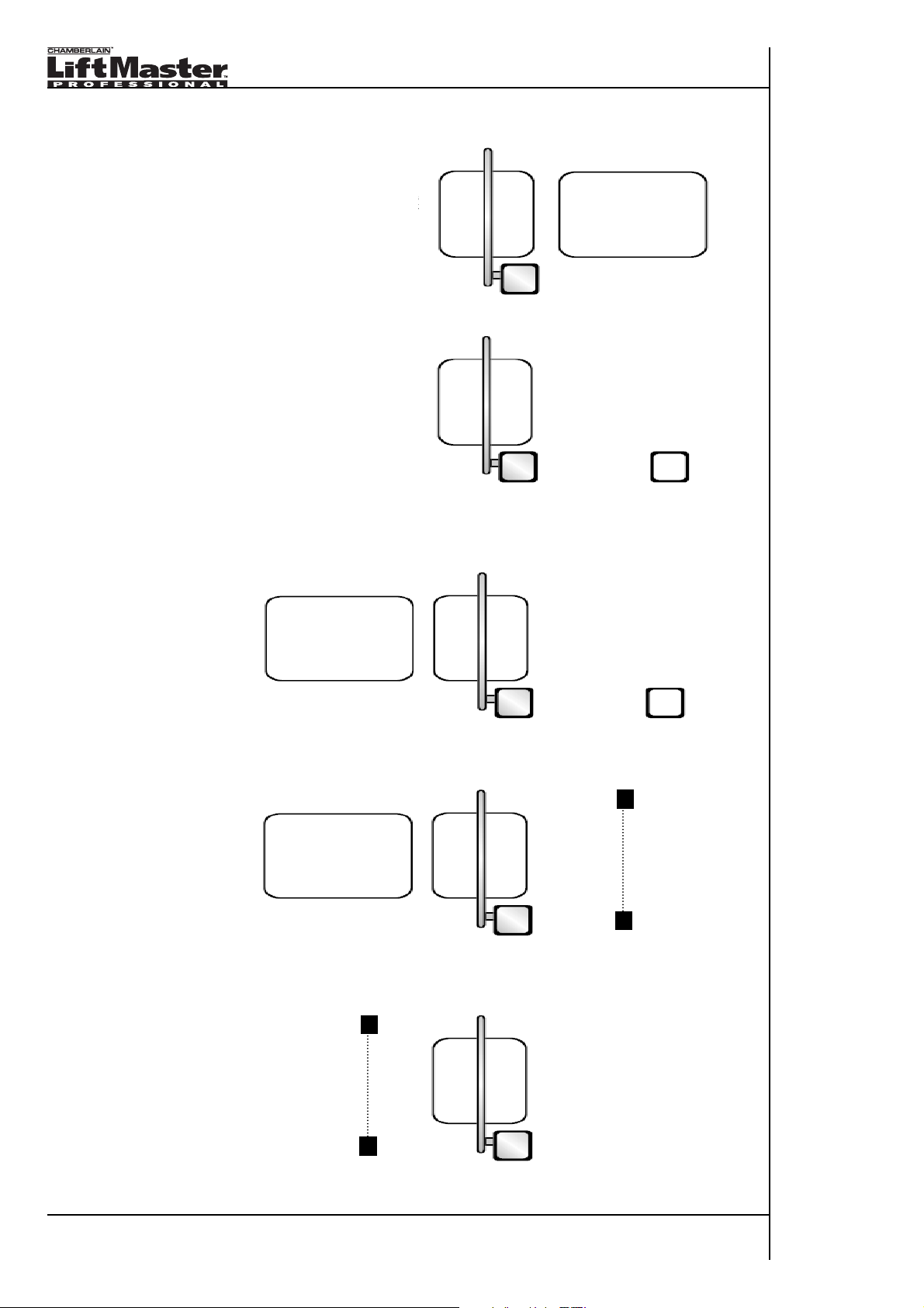
4.1 Example 1
Free exit
Safety loop and loop for automatic opening
of barrier. Distance between loops: 1.0m
4.2 Example 2
Opening by means of switch / push button /
card reader or safety loop. This installation
represents an entry or an exit.
4.3 Example 3
Safety loop. Opening on one side by means of switch / push button / etc. In order to exit: loop for
automatic opening of barrier. Distance between loops: 1.0m
4.4 Example 4
As in examples 1 and 3, but with Photocell for opening barrier from the inside as opposed to loop
for exiting.
4.5 Example 5
Safety loop underneath barrier and additional Photocell for added safety.
Note: example only applicable to one-way traffic!
Page 12
12/40
Notes
5 Operation description
5.1 Operation of barrier
Barriers are available in models Right / Left. The casing is made of welded sheet steel (apart from
specific models) and is powder coated against corrosion. The drive unit and control are integrated
into the casing and accessible by lifting off the hood and opening the service door.
The drive motor is powered by the control and is fed by line voltage. Force and rotary motion are
transferred by a leverage system.
This leverage mechanism is defined ex works by a slow deceleration in both directions in case of
quick movement of barrier.
The effective force is limited through the applied capacitor and is defined ex works.
An incorporated sensor reverses the barrier in the direction OPEN if an obstacle should be hit.
The maximum run time of the motor as well as the opening time of the barrier are determined by
the drive in use and the time setting on the control (1-3-6 seconds).
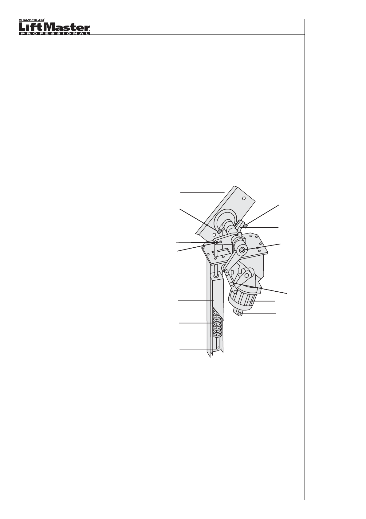
5.2 Description of parts
1. Slot for emergency release key
2a. End stop screw OPEN
2b. End stop screw CLOSE
3. Intermediate lever
4. Spring setting
5. Barrier pole bracket
6. Tilting lever Hole 1
7. Tilting lever Hole 2
8. Spring casing
9. Spring
10. Sensor
11. Motor
2a
6
5
2b
1
7
3
8
11
10
9
4
Page 13

13/40
Notes
5.3 Operation of barrier (straight pole)
Barriers with straight barrier posts are available in different
lengths. The straight pole moves from horizontal to the complete
vertical position. Short barrier posts can be opened very quickly (1
second), long posts must be openend more slowly (3 / 6 seconds)
in order to ensure lasting and safe operation of unit.
5.4 Operation of barrier (90° articulated pole)
The 90° articulated pole is used when there is only limited height
available or an ensuing height restriction is indicated at the barrier
(limited to car entry only). These types of barriers open in 3 – 6
seconds. For dimensions see Technical Data.
5.5 Operation of barrier (180° folding pole)
The 180° folding pole operates similarly to the 90° version. The
difference is that the pole is swung completely out of the way. This
leads to a height saving which can be used otherwise. This type of
barrier requires at least 3 seconds to open. For dimensions see
Technical Data.
5.6 Operation of barrier (lattice/fence)
(in preparation) The lattice barrier is used in combination with the straight barrier pole. The lattice
moves with the barrier pole and visually keeps pedestrians from passing through the barrier resp.
redirects to a pedestrian path. These barriers work slower due to additional weight – normally 6
seconds.
5.7 Operation of motor
The rotary motion of the motor is transferred to the axle via a buffer lever. The characteristic
mechanism lets the barrier open slowly at first, then it accelerates it and finally slows it down again
before reaching the end position. This prevents the barrier pole from slamming and helps increase
the life span. The special mechanics results in the barrier being totally irreversible and for the
mechanics to break down first. This renders the barrier extremely durable and in case of
vandalism or the barrier pole being damaged – only the barrier pole has to be replaced.
5.8 Operation of spring (balancing spring)
There are 2 resp 3 springs (depending on model) under the casing’s hood. The main spring and 2
buffer springs. The main spring is responsible for the balancing of the barrier pole and the prestressing is adjusted according to barrier pole length. The buffer spring or emergency spring
guarantees a smooth travel and serves for added safety in case the main spring should break.
5.9 Operation of limit switches
End stops are attached to the intermediate lever as well as the limit levers, which have been
preset ex works to the 90° movement. A contact-free limit switch shuts the control off. After the
preset time the control shuts off the motor. An exact setting can ensure the shortest possible motor
run time, preventing the motor from heating up unnecessarily when travelling towards the end
stops and shutting down in this position after some time.
Page 14

14/40
Notes
6 Installation
6.1 Foundation construction: barrier
A stable position of the barrier casing is imperative. We recommend a foundation with the following
minimum requirements. If there is a risk of frost, the foundation must be constructed in a way as to
ensure protection against frost – so the ground does not rise. All necessary ductwork and wires
have to be led out of the center of the barrier’s pedestal.
• Duct for power supply
• Duct for Photocell
• Duct for control wires
• Duct for loop connection 1
• Duct for loop connection 2
• Etc.
Barriers up to 6m
Depth: 900mm
Diameter: 500 x 500mm
Barriers up to 8m
Depth: 1 400mm
Diameter: 500 x 500mm
The upper pedestal area is to be constructed in a smooth, flat and absolutely horizontal way with
regard to the road, so the barrier casing can be mounted vertically. The used concrete should
comply with hardness BH PC 250 (25N/mm2). The pedestal must be constructed with solid steel
reinforcement. The drilled holes are to be designated according to the dimensions and to be
fastened to the composite anchors (Ø 20mm x 110mm).
6.2 Foundation construction: tip support post (support)
In order to mount the support, a stable and inalterable location is required. The support is fastened
by means of composite anchors (not included in delivery).
500
500
900
500
[ mm ]
500
1400
500
500
282
325
[ mm ]
150
Page 15

15/40
Notes
6.3 Contact loops (induction loops) – description
A contact loop reacts to metal and is especially suitable for safe operation of barriers.
The dimensions, number and installation of loops has to be executed with great care.
Principally the following applies:
• Control loops prevent a premature closing. The most important loop for this is located underneath
the barrier pole (see Examples) and has to secure the entire length of the barrier pole. As long as
the vehicle is standing on the loop the barrier cannot be closed. After leaving the loop the
automatic closing mechanism is activated. This may happen immediately or after a short delay.
• Opening loops are installed infront of barrier unit and activate it like a switch. The distance
between both loops may be 1m at the most. Larger distances may cause problems with short or
slow vehicles.
• Motorbikes and bicycles can also be recognized by the loops. For this purpose special lanes must
be created and identified (e.g. Motorbike Lane). A car loop cannot be a motorbike loop and vice
versa.
• The loops should be installed at a minimum depth underneath road surface. The deeper the loop is
situated the less the detection. Particularly vehicles with higher ground clearance and also trailers
might therefore not be detected. The detection of trailers or campers is difficult due to their flooring
often being made of wood and thus not being detectable until axle crosses the loop. Either a
second loop has to be installed behind the barrier which the pulling vehicle must cross first or the
automatic closing has to be adjusted according to the trespassing speed. Photocells may be
installed as an alternative for added security.
Zul
eit
ung
S
c
hleifenve rlegung
Drauf
s
icht
Zuleitun
g
E
cken di
E
in
f
r
ä
s
un
agonalgeschn
gDrau
fs i
ch
t
itten
Page 16

16/40
Notes
6.4 Installation of induction loops – general
The geometry has to be executed depending on unit:
• The loop has to be positioned exactly underneath barrier pole. The barrier pole is positioned on the
side of the barrier casing.
• The monitored area for cars has to be at least 500mm on both sides. For trucks the loops have to
be larger or a second safety loop must be installed.
• Keep loop at a distance of 300 – 400mm from road side.
• Faulty road surface, cracked areas, moving subsoil, loose paving, coarse gravel, metal parts may
be diagnosed as errors and thus disturb the operation. The subsoil must be stable and rigid.
• Avoid iron reinforcements in the road. This may lead to the loop being disturbed. Keep >50cm
distance from iron.
• Heated roads also disturb loop (keep > 100cm distance)
• Garage doors, rolling gates, sliding gates and wing gates disturb the loop’s operation if made of
steel. Keep a distance!
• The distance between the loop’s control and the loop itself may be max. 15 – 20m. If that is not
possible the diagnosis unit must be installed outside the barrier unit.
• The cable of the loop must be fitted exactly. Coiled cable interferes with analysis.
• The loop’s resistance must be checked after installation. It shoul be about 0.8 – 2.0Ohm. The insu
lation resistance against ground must be larger than 1MOhm. The inductance of the loop must be
between 70 - 500μHenry.
Page 17

17/40
Notes
6.5 Installation of induction loops – procedure
Installation under asphalt or concrete:
• Size and positioning of loop(s)has been decided upon. Mark positions on the ground and check
again.
• The corners of the loops are to be executed at an angle of 45°. See Illustrations.
• By means of a cutting disk or similarly suitable tool a furrow must be cut into the road with a
depth of 50mm. the width of the furrow must allow for the cable which will be inserted at a later
point in time. The loop must lie evenly deep (parallel) with regard to road.
• The furrow must be very clean! A vacuum cleaner is ideal to remove dirt and small obstructions.
• The loop is laid with one insulated wire with a profile of 0.75mm² to max. 1.0mm² in diameter.
3 – 5 windings are laid. Now resistance and inductance can be measured.
If supply has already been installed then do a check!
• Secure loop with a plastic or wooden spatula.
ATTENTION: Do not damage cable insulation!
• Both wires are intertwined with one another in the supply line to the loop (between loop
evaluation and actual starting point of loop) in order to prevent another loop from occurring
• The supply line is led to the evaluation or is wired through the ductwork into the barrier casing
• The loop cable is now covered with fine quartz sand in order to fill the gaps between cable and
wall. At least 25mm have to remain free to road surface
• The furrow containing the loop can now be closed up. Take care when using hot potting
compound, such as bitumen! Temperatures of 90°C damage the cable isolation and destroy the
loop. Laying under interlocking stone pavement. Pay additional attention!
• There has to be enough room between the individual stones of the pavement and the loop
(30mm). The stones may move in the course of time and damage the loop.
• The loop is laid as described above with 3-5 windings – not directly into the sand but through a
customary plastic duct with a small diameter. The diameter must be small in order to prevent the
cable in the loop from moving in case of vibrations (car). The windings can also be held together
by means of cable ties. The plastic duct prevents dirt from entering due to the weight of the cars.
These measures should be prepared in the workshop and not as late as on site. The loop can
also be tested in the workshop by placing it partly under a parked car.
• The duct in which the loop is laid is to be marked and excavated. Position loop inside and cover
with fine quartz sand. Do not use grit or gravel, as these materials do not remain firm and stones
may damage the loop.
Page 18

18/40
Notes
6.6 Installation of operation switches
Operation/command devices must be placed such as to ensure easy access from inside the
vehicle. They must be in direct visual contact with regard to barrier. Poorly placed switches and
pillars represent possible safety hazards.
6.7 Usage of Photocells
Photocells are especially suitable as an alternative to a contact loop; though even more effective
in combination with a safety loop. Especially when trailers, campers or trucks with trailers pass
through the barrier, Photocells are perfect. Ideally Photocells are positioned directly under the
barrier in order to recognize an object and delay the closing motion. They may also be installed
behind a barrier so as to send a further signal and thus prevent the barrier from closing or delay
the closing motion some more. The height of the installation depends on the situation and should
be located at a position which does not let the invisible light beam transmit underneath the
vehicles (truck, SUV).
Reflector Photocells are not suitable for operation, as vehicle finishes, sun or strong rain lead to
incorrect reflector operation.
Page 19

19/40
Notes
7 Mounting
7.1 Service door
The included key (2 keys) is necessary to open the service door. It can
be found in the accessory package which is included in the barrier’s
transport packaging. On the inside of the service door the already preinstalled and partly wired control is situated.
Attention: Inside the barrier electrical parts are located which are live
wired!
WARNING: The mechanics inside of the barrier can lead to serious
injury if barrier is activated.
7.2 Removing the hood
Attention: Disconnect barrier from power supply. Inspection necessary!
The hood is secured by means of a wing nut which is only accessible
when service door is open. In order to remove hood, reach into barrier
with hand and remove wing nut (twist off). Now lift up hood on door
side, approx. 2cm.Then, in lifted position, move backwards in the
direction of barrier pole and lift hood off completely.
Note: Hood is secured with one wing nut. A second one may be used if
necessary. This is not required for technical reasons. It is impossible to
remove a hood that is secured with a screw without this leading to
strong and lasting damage.
To place hood back in original position go through above steps in
reverse order.
Transport: For transport a plastic film is placed between hood and
casing in order to prevent the finish from getting damaged.
This precaution may be removed upon installation.
7.3 Release (manual operation)
For this purpose the release key is necessary which can be found in
the accessory package of the barrier.
On the side where the service door is located there is a drilling in the
hood. The release key must be inserted here and in order to release
barrier the key must be turned clockwise.
Barrier may only be locked again as in the initial position when
released. If barrier was closed never leave barrier pole unsecured in
open position, as it may move downwards unchecked.
The manual
release is reserved for emergency situations or in case of maintenance
work and is not suitable for daily use.
The release function can be deactivated and is thus not accessible from
the outside if misuse is to be expected. For this purpose find enclosed
in the accessory package a small fastening which can be inserted into
the release drilling before the hood is put on.
Page 20

20/40
Notes
7.4 Mounting the barrier (casing)
Note: 2 people required! The necessary parts can be found in the accessory package included in
the delivery contents of the barrier.
2x U-profiles
4x composite anchors Ø20mm x 110mm long
• Indicate drillings for composite anchors and prebore
• Position barrier and tighten screws slightly
• With barriers up to a length of 4m the final alignment can be executed after mounting the barrier
pole
• With barriers longer than 4m the alignment must be executed immediately (without barrier
pole) and the screws are tightened firmly
ATTENTION: It is important that the composite anchors are fitted well in order to prevent barrier
from becoming dislodged. Especially in case of long barrier poles this can be dangerous!
• The gap between the base of the barrier casing and the pedestal has to be grouted with silicone
to prevent moisture from entering (important for protection against corrosion).
7.5 Mounting the tip support post (support)
Mounting the pole strut should be done after barrier pole has been fitted and aligned.
Installation is executed by means of composite anchors (not included in delivery) in the
ground and on a solid and stable subsoil.
A pendulum support is available as accessory.
7.6 Mounting the barrier pole (straight)
Attention: 2 people required to secure barrier pole.
Barrier must be in “Closed” position. Barrier pole is slid onto attachment and fixed in place by
means of the cover plate and the two provided screws (accessory package barrier). The nut must
be put on from the outside resp. the screw is to be slid through from the inside out. The barrier
pole has to have a firm fit on the arm and must not move nor have any clearance. The screws
allow tightening. If the screws appear to be too short to begin with, omit the washer and/or the
circlip. After tightening both screws slightly, loosen one screw and remove it in order to provide
washer and circlip. Tighten screw again and now retrofit other screw.
BARS = 2x
BARM = 2x
BARL = 4x
180
180
Page 21

21/40
Notes
7.7 Adjusting the length
The unmounted barrier pole is longer than actual barrier operation width.
This width is always 270mm shorter.
If a barrier pole support is used then operation width is decreased by about 100mm.
The barrier pole cannot be shortened on the side of the drive but on the opposite end.
The end cap can be removed and then the length of the pole can be adjusted.
7.8 Mounting the barrier pole (90° articulated)
Mounting these barrier poles at the axle is the same as with the straight version. See Mounting the
barrier pole (straight).
Before fitting the barrier pole the articulated-guide must be installed. Furthermore see Mounting the
articulated-guide and Fixation and setting of push rod for articulated barriers.
Note: The full length (max. 3200mm) articulated pole may only be used in combination with
barriers with a run time of 3 to 6 seconds. Barriers with run times of 1 second may only be used in
combination with articulated poles of max. 2500mm length.
7.8.1 Mounting the articulated-guide
The articulated-guide is installed behind the pivot point of the
barrier pole. It is essential that the necessary drillings are
executed accurately. There is near enough zero tolerance in this
case and inaccurate works cannot be compensated. If the articulated-guide is wrongly positioned the pole cannot be set and
hangs downwards, stands upwards resp. a final position is not
adjustable.
Note:
This work should not be done on site, but should be
prepared in the workshop.
Adhere to the following course of action:
• Position barrier without pole on a solid surface (workshop) and
remove hood (see Removing the hood)
• Relax barrier spring and remove (see Setting of springs)
• Release barrier by means of key and turn in open direction
(see Release)
• Take accurate measurements of drillings for articulated-guide,
indicate and prebore with no more than 4-5mm. After that bore
through with 8.5mm
• The measurement from the upper plate to the upper drillings of
the fitting is crucial and equals 45mm. The drillings located
below are set 50mm lower
• The measurement from the centre of the rotation axle of the
barrier to the first of the two drillings is 83mm (horizontally).
The drillings behind are 40mm further away.
• Between articulated-guide and casing there is another plate.
This plate is important because the casing cannot be mounted or
removed otherwise
• Due to engineering the threads of the articulated-guide are first
cut and then varnished. Please check condition of threads. If
need be spray with oil to ensure that the screws can be fitted
more easily
• It is advisable to work with a long extension in order to fit and
tighten the screws
• The articulated-guide must have a firm fit and not have any
clearance
• Fit casing and check
• Then refit barrier spring and go through steps above in reverse
order. But do not tension spring yet, merely put nut back on
+
83
123
95
45
50
O 8,5
[ mm ]
[ mm ]
45
95
50
83
123
Page 22

22/40
Notes
7.8.2 Adjusting the length
The articulated pole can only be shortened at the end behind the articulated mechanism.
All other parts are already adjusted to correct measurements ex works.
7.9 Fixation and setting of push rod for articulated barriers
Familiarize yourself with all parts of the push rod. See illustration.
Attention: 2 people necessary!
Adhere to the following course of action:
• Attach the two screws on the left and right hand side of the articulated pole-fittings and tighten
them (if necessary use oil spray). These screws serve for the adjustment of the fitting.
• Insert axle around which the push rod will rotate. Pay attention to correct alignment. One side has
a slanted edge and faces towards the push rod. Tighten by means of acorn nut, washer and
circlip (as shown) in the long slot (in the centre)
• The barrier spring must not or hardly be tensioned
• Now install the barrier pole as afore described
• Release barrier and position horizontally
• Insert push rod. The push rod is pre-assembled but not set precisely. Turn rod as long as it takes
to reach correct measurement. The threads are left/right threads. Pay attention when sliding
bearing onto axle! Mind the correct side! In the eye of the push rod’s bearing there is a circlip. It
must point towards the barrier otherwise the clip will be jammed by the nut. This is why the axle
has a slanted edge on one side.
• Use long acorn nut with washer and circlip
• Setting: by rotating in the centre of the push rod the position of the barrier pole can be adjusted
• The slotted hole serves the alignment in the horizontal position
• The push rod serves the alignment in the open position
• Final setting is not advisable until barrier is operated electrically and limits are correctly set
7.10 Model barrier left / right and conversion
The barriers are pre-assembled in the following versions: “Left” or “Right”.
Principally all parts of the barrier can be used both ways. Retrofitting must be authorized in writing
by the manufacturer.
Page 23

23/40
Notes
8 Spring balance
The spring in the barrier equalizes the weight of the barrier pole. It is essential that the correct
spring is combined with the correct barrier length. If the barrier pole is not balanced the unit does
not work well, the barrier does not close/open completely and the life span is drastically shortened.
8.1 Testing
Release barrier and lift barrier pole manually and let go in the following different positions: 15°,
30°, 45°, 60°. The barrier pole should not move from these positions. It remains in the unhanded
position only held by the spring. If the setting is incorrect readjust spring setting.
8.2 Spring setting
Depending on model used different springs have to be used in order to balance the pole length.
Springs:
Pole length Lever drilling Spring diameter
2.5m 3.5m 2 5.5mm
3.5m 4.5m 1 5.5mm
4.5m 5.0m 2 6.5mm
5.0m 6.0m 1 6.5mm
6.0m 7.0m 2 7.0mm 2 springs
7.0m 8.0m 1 7.0mm 2 springs
Additionally there are two drillings situated at the lever of the barrier shaft. These drillings amplify
or reduce the force of the spring. If the pole length is borderline between the indications then use
the drilling further away from the rotation axle. The spring has a longer life span if less tensioned.
Attention: before retrofitting to a different drilling relax spring! The barrier pole, if already mounted,
has to be in the CLOSE position (horizontal).
8.3 Correcting spring settings
With open barrier the spring force can be adjusted through the service door.
It is a right-hand thread setting. Screwing in heightens the spring force.
Screwing out reduces the spring force.
1
2
1
2
Page 24

24/40
Notes
8.4 Removing the spring
Attention: if the spring is to be exchanged in one operational step then follow the steps below.
If unit is left unmonitored without spring then the barrier must be closed and secured against being
opened – or the barrier pole must be dismantled.
The power supply must be cut thus preventing the barrier from being operated.
• Remove barrier pole
• Cut power supply
• (1) Dislodge barrier spring: for this purpose the setting of the spring must be turned far down.
By applying pressure on the inner casing of the spring with your fingers (1A/1B) it can be
dislodged.
• (2) Loosen lever screw and lower spring
• (3) Loosen the 4 screws (depicted in illustration) and lower spring casing
• (4) Now the spring can be removed including rod and case
• Repair, maintenance, inspection or exchange can now be conducted
• Reassemble by following steps in reverse order
1
1A
1B
2
3
4
Page 25

25/40
Notes
9 Electric connection
The barrier must be connected to grounded mains. The connection must be executed
professionally and must comply with the relevant norms and guidelines of the installation site.
The offered models are partially wired ex works in their standard versions. Special edition models
may differ from this pattern and may include other controls.
9.1 Connection to supply voltage
The power supply is connected to the main switch situated on the inside of the casing. The strain
relief for the cable of the supply line has to be executed on site and can be done as shown.
9.2 Earthing
The grounding is connected to the specially designated clamp and must comply with the relevant
guidelines of the unit’s installation site.
9.3 Main switch
All standard models are equipped with a main switch, which disconnects the voltage supply at all
poles. It serves to ensure safe handling when maintenance and inspection work is executed or in
case of shut down. If unit is not in operation the switch must also be labelled with the necessary
information in order to prevent from being switched accidentally.
9.4 Handling in case of power failure
If the power supply to the barrier is cut and there is no alternative 230Volt supply
connected the barrier will stop. Programmed settings remain stored. The barrier is able
to operate again within seconds after switching the power supply back on.
Note: if barrier is in completely open position it will close automatically after programmed
time has elapsed. If barrier is positioned between the limit switches then a signal is
needed to open or close the barrier.
9.5 Electrical protection of unit
• The electrical backup of the entire unit must be done with 5A
• The control is equipped with a 5A glass fuse (5x20)
• The motor has an automatic protection against overheating (after cooling down the motor
switches itself back on : switches off at 140°C and switches back on at approx. 75°C
Page 26

26/40
Notes
10 Control unit
The control is a modern design micro controller and is purely designated and conceived for the
operation of these barriers. The control already has many integrated functions.
10.1 Functions of control unit
• Automatic closing (adjustable)
• Immediate closing after clearance of loop
• Photocell entry
• Loop entry
• Exit for signal barrier closed
• Separate OPEN – CLOSE – STOP signals
• Traffic light control red – green
• Cooling fan control (not all models)
• Diagnostic LED’s
• Plug-in socket for radio connection
• Signal relay when barrier open
• Signal relay when barrier closed
10.2 Control unit’s modes of operation
The modes of operation result from the connection of accessories and control components to the
control. The following description sums up the generally used modes of operation:
• Manual OPEN: barrier is opened via switch/push button and closes automatically after lapse of
programmed time or stays in open position until signal to close is given. An optionally connected
loop or photocell prevents barrier from closing if vehicle is standing in barrier’s way
• Manual OPEN – radio control:
in addition with connected radio control unit for OPEN/CLOSE or
OPEN and CLOSE. Remote control with at least 2 channels necessary
• Automatic:
in addition (without radio utilization). On one side of the barrier a loop or photocell is
located which opens the barrier and, after clearance through another loop, closes barrier again
Note: if traffic occurs in both directions at barrier, it must be taken into consideration that vehicles
driving in the opposite direction also activate the loop and the closing time is thus delayed.
Exception: 2 loops with direction recognition.
10.3 Operation via radio
• Operation of barrier via radio is possible, but the barrier must be within direct sight. Closing the
barrier via radio is not advisable. Safety devices against closing in danger zone should definitely
be used.
• For connection see Description of socket connectors -> RADIO RECEIVER
10.4 Connecting control unit
The control has been connected to main switch, motor, limit switches, fan (if installed) ex works
and has already been tested regarding correct operation and is generally pre-programmed
(standard models). If main switch is supplied with voltage and switched on the control is live wire.
Page 27

27/40
Notes
10.5 Installation description of control unit
10.5.1 Description of screw terminals
• Motor: outlet to motor 230V
o L = black or brown
o N = blue
o L = brown or black
• POWER LINE: connection voltage 230V of control
o L
o N
o Grounding
• RED/GREEN (G; COM;R):
connection to red/green traffic light
Outlet operates without adjustable delay
Outlet is potential-free: max. 10A
o G = green, when barrier open
o COM = neutral conductor
o R = red, when barrier closed
• PHOT
O POWER OUTPUT: connection accessory, e.g. Photocells
o 12VAC
o Max. 250mA
• DOWN LIMIT OUTPUT
: connection for signal relay – barrier CLOSE
to peripheral devices or controls
o Voltage free outlets. Not suitable to operate 230V or load.
o COM: joint contact
o NO: “Normally Open” contact
o NC: “Normally Closed” contact
• SPECIAL
FOR MOTORCADE:
Description: The incoming signal “Motorcade” is connected to the function
“Vehicle Detector Signal”, which situated directly adjacent.
Contact type: N/C Open
1. the combination prevents the closing of the barrier because further vehicles
are to pass through the barrier. For this purpose the signal “Motorcade” is
used in addition to the “Vehicle Detector Signal” in order to control the barrier’s
operation.
2. alternatively connect contact loop as an opening contact (NO = Normal Open)
instead of an NC.
Starting up the terminal: with most models the inlet is switched off (not active)
ex works. In this case there is a small soldered wire jumper (specification 5V)
underneath the Motorcade clamp. If it has not been soldered then a wire
jumper must be inserted into control contact or a suitable accessory must be
connected as described below.
Page 28

28/40
Notes
Note 1: The pace of the vehicles should be slow. All examples should be adapted to the local
situations. All of the following examples are executed without oncoming traffic.
Note 2:
Not suitable for operation with trailers.
Note 3:
As a third safety device it is necessary to place a Photocell under the barrier pole
Note 4: Automatic closing after a certain (preset) time is not possible with this function
Note 5: It is important to understand the Vehicle Detector Signal – function
Example 1: Entry OR Exit
• A contact loop is installed underneath the barrier and connected to the input Vehicle Detector
Signal as N/O contact (closer)
• A further loop or Photocell which is connected to the Motorcade input should be installed with a
clear distance to the first loop in front. The first vehicle of a motorcade should NOT activate both
loops simultaneously
• Description of process: one vehicle activates the immediate closing of the barrier unless
another vehicle is already blocking the Photocell (loop) transmission which has been installed
keeping some distance from the contact loop. Then the barrier stays open, as no signal can be
transmitted.
Example 2: Entry or Exit
• A contact loop is installed underneath the barrier and connected to the input Motorcade as N/C
contact (opener)
• A further loop or Photocell which is connected to the Vehicle Detector Signal input should be
installed with a clear distance beyond the first loop. The first vehicle of a motorcade should NOT
activate both loops simultaneously
• Description of process: vehicle drives over loop and underneath barrier without the control
reacting until the Photocell (loop), which has been installed with some distance from the first
loop, is activated. If there is another vehicle on the loop underneath the barrier by then, the
barrier remains open until the Photocell (loop), which is positioned beyond, is reactivated.
• VEHICLE DETECT
OR SIGNAL: input for safety loop
The loop detector is connected in away as to close (NO) a relay when a vehicle is standing or
moving underneath the barrier. Effective March 2009, controls with NC
contact (inverse func
tion) are also in use. In this case a jumper is factory installed in the controller. In case of closed
relay contact it is possible to open barrier but not to close it. If barrier is OPEN there will sound
a warning signal via a beeper on the control unit indicating that a vehicle is standing on the
loop. After the loop is released (relay open again) the barrier closes immediately. If a vehicle
drives onto safety loop during closing motion the barrier reverses to OPEN.
Note 1: If you wish to delay the release because barrier should not close
straight away, then this delay has to be adjusted at the loop detector (relay
drop delay).
Note2: The input can also be operated ac N/C contact
(opener) in combination with adjacent input Motorcade.
See input Special for Motorcade.
• Contact open: inactive
• Contact closed: active
Page 29

29/40
Notes
• SERIAL COMMUNICATION
o Inactive for these barrier models
• LOOP
– output to loop
o Only if socket VEHICLE DETECTOR SOCKET is occupied
o The functionis identical to output: Vehicle Detector Signal
• PHOT
O SIGNAL
INPUT
Terminal for Photocell input N/O contact (closer)
2 modes of operation possible:
Adjustment via DIP switch 3
DIP switch 3 OFF:
Photocell keeps barrier from closing. If automatic closing is activated (preset time), this time runs
in the background (= is not reset to beginning). After release of photocell the barrier closes
immediately.
Note 1: Install Photocells in height of vehicle body (sheeting height), not in height of wheels
(600-800mm)
Note 2: Photocells are installed after barrier has been mounted – as a second safety device
Note 3: A unit where automatic closing is activated should not be secured solely by means of
photocells. A loop is more suitable. Especially bear this in mind with fast closing barriers
(1&3 seconds)
DIP switch 3 ON:
Photocell opens. As soon as Photocell is interrupted the barrier opens. If automatic closing is
activated (preset time) this time runs in the background (0 is not reset). After time has elapsed
the barrier closes, no matter if the Photocell is still active. This mode of operation is only suitable
to let a single vehicle exit.
Note: the automatic closing time is reset when, while the barrier is open, another command is
given for the barrier to OPEN, which is applied for at least 1 second.
• UP
LIMIT OUTPUT:terminal for signal forwarding barrier OPEN to peripheral equipment or
controls
o Voltage-free output. Not suitable for 230Volt or load operation
o COM: joint contact
o N/O: Normally open – closer
o N/C: Normally closed - opener
• SIGNAL
INPUT:input for switch
o All terminals N/O (closer)
o COM: joint connection
o UP: input barrier open
o DOWN: input barrier close
o STOP: input stop-switch
Note: if there is a continuous signal applied at the UP contact the barrier remains open. If a closing
time has been preset the timer will start countdown after contact has been released.
• VEHICLE DETECT
OR SOCKET: plug-in socket for loop diagnosis with universal socket
o The socket in question is a universal socket which can be used with standard loop diagnosis
units. The loop itself is connected via the outputs: LOOP.
Note1: Prior to installation ensure that the applied detector fits into the control box (overall height),
otherwise a different model must be fitted externally
Note 2: Prior to usage of diagnosis unit check compatibility. See Terminal occupancy of socket.
A list of reference with compatible diagnosis units may be obtained through the customer service
department (August 2008 in preparation)
Page 30

30/40
Notes
10.5.2 Description of socket connectors
• SHORTCUT CONNECTOR: terminal blocked for particular type of loop detector. Cable not
included in range of offer. Serves the same purpose as the VEHICLE DETECTOR SIGNAL
• CAP
ACITOR X2: capacitor terminal
o Power: 2x 9μF/450Volt
o Clamp occupancy from left to right:
• COM
• C1
• C2
• LIMIT SIGNAL
INPUT: limit switch terminals
o Terminals for limit switches
o Clamp occupancy from left to right:
• Red
• Green
• Yellow
• Black
• SENSOR:
rotation sensor terminal
o Sensor monitors motor rotational speed. If barrier is brought to a standstill (hits obstacle) during
travel (down) the barrier reverses. The sensor is located at the bottom of the motor and is
equipped with LED’s for operation control.
o Clamp occupancy from top to bottom:
• Red
• Black
• Brown
• RADIO RECEIVER:
external radio terminal
o Terminal for radio receiver, which is installed outside of the control in a suitable casing.
The connecting wire is included in delivery contents of standard barrier models. If a signal is
transmitted from the radio receiver to the control, then the beeper on the control unit sounds as
a means of verification and indication for the time of the given impulse.
o Possible receiver models
• 8002E 2-channle, 15 remote controls each per channel IP57
• STAR250-433, 1-channel Management System for 250x remote controls; box for external
installation must be ordered separately
NOTE: in order to use a radio code lock a receiver of the above mentioned models is necessary
o Clamp occupancy from left to right
• COM 5V COM red
• Stop signal stop black
• Down signal close yellow
• Up signal open green
• Not occupied brown
• TEST
: Motor fan terminal (in barrier motor)
o Operation of fan is possible via TEST switch
o Not all barrier models are fitted with a fan ex works
o Clamp occupancy from left to right
• - (minus)
• Test
• + (plus)
• COMMUNICA
TION MODULE
o Socket presently not usable
A
B
C
D
G
E
F
Page 31

31/40
Notes
10.5.3 Description of switches
• FAN: test switch for fan operation ON/OFF
o If a fan is installed in the barrier, see occupancy socket: TEST (resp. model), it can be tested
with this switch
o Normal setting: OFF
o Test setting: ON
o NOTE: if motor temperature rises above 70°C the fan automatically starts
• BARRIER SELECT
:
o Setting of used gear type. Is preset ex works to correspond with bought model.
No retrofitting necessary
o 1 sec = for barriers with run time of 1 second
o 3 sec = for barriers with run time of 3 seconds
o 6 sec = for barriers with run time of 6 seconds
NOTE: the speed of the barrier is determined by the gear and not by the switch. Wrong settings
may interfere with barriers logic and cause disturbances!
•
AUTO DOWN / TIMING: (automatic closing)
o Setting of the time which determines how long the barrier is kept open.
By adjusting the setting of DIP switches 1 and 2 determined times are programmed:
DIP1 DIP2 TIME
OFF OFF OFF
ON ON 5 seconds
OFF ON 10 seconds
ON OFF 20 seconds
NOTE: DIP switch 3 has a different function. See Photocells.
J
I
H
Page 32

32/40
Notes
10.5.4 Description of signal LED’s
• POWER
o Colour: red
o On: power on
o Off: no power supply
• UP
o Colour: red
o On: signal OPEN applied
o Off: no signal
• DOWN
o Colour: red
o On: signal CLOSE applied
o Off: no signal
• STOP
o Colour: red
o On: STOP active ( no movement of barrier possible)
o Off: STOP not active
• PHOTO
o Colour: red
o On: Photocell locks functions
o Off: Photocell unobstructed
• VEHICLE DETECTOR
o Colour: red
o On: output active
o Off: output inactive
• DOWN L.M. (limit)
o Colour: red
o On: limit switch CLOSE active
o Off: limit switch inactive
• UP L.M. (limit)
o Colour: red
o On: limit switch OPEN active
o Off: limit switch inactive
•
symbol (motor rotation direction OPEN)
o Colour: red
o On: relay active
o Off: relay inactive
•
symbol ( motor rotation direction CLOSE)
o Colour: red
o On: relay active
o Off: relay inactive
• 2x Signal LEDs “without description”
not functioning
Page 33

33/40
Notes
11 Adjusting the barrier
The power supply and at least one switch OPEN-CLOSE must be connected. The barrier pole has
to be installed and balanced.
Attention:
the traffic lane and the area surrounding the moving barrier pole must be
blocked from traffic in the mean time.
11.1 Adjustment of limit switches
The adjustment of limit switches is only possible if barrier pole is balanced.
The barrier can execute movements up to 90°.
Attention DANGER:
Each time adjustments to limit switches are carried out the main switch
must be turned off. All operational components have to be secured to ensure that they
cannot be operated inadvertently.
Technically the Limit switch is a photocell which is located in a small case under the hood.
The limit is activated by a finger that interrupts the sensor beam. A LED indicates if a limit is
reached. Factory-provided the barrier is preset and only minor corrections should be needed,
if at all.
11.2 Correcting the limit switch adjustments
• turn off main switch
• remove barrier hood
• release barrier and lift into final position manually. The corresponding limit switch (LED on limit
switch) lights up, if the final position is reached electrically
o Correcting adjustments:
o Losen finger from shaft until it can be moved with little force.
o Move barrier to desired limit.
o The LED must light up in final position, but also as soon as final position is abandoned
Correct function:
Barrier is switched off via Photocell and limit stop buffers are hardly or
only very slightly pushed in
• Turn on main switch and check result
11.3 Adjusting length of connecting arm between motor and barrier axle
The length of the pole has been adjusted ex works and must not be changed!
In case of adjustment being too short or too long the barrier does not reach the final position or
travels beyond final position. Then the slow travel at the end of the up or down movement does
not occur. The pole slightly touches on the limit buffers if correctly adjusted!
Page 34

34/40
Notes
12 Completion (finalizing installation)
• All electrical connections must be correct
• All safety devices must have been checked concerning proper function
• All modes of operation of unit must have been tested
• All mechanical parts must be securely tightened. Even if no adjustments have been carried out
on mechanical parts ALL setting screws and connection screws of
o Spring
o Spring pole
o Barrier pole must be checked.
• The control unit must be closed tightly and in accordance with regulations
• The strain relief at the bottom of the control has to be checked and, if necessary, tightened
Page 35

35/40
Notes
13 Trouble shooting and FAQ’s
13.1 Barrier does not work (no movement) (refer to 13.2)
13.2 Does not open
Description Remedy / Reason / Solution
13.3 Does not close
Description Remedy / Reason / Solution
- barrier shows no reaction
- NO LED lighting up in control unit
- power supply interrupted
- main switch turned off
- protection switch F1 has triggered
- fuse in control unit has blown
- Voltage is applied up to control unit
- LED’s on control unit are off
- fuse in control unit damaged
- overload due to connection of damaged
accessory (short circuit)
- Voltage is applied up to control unit
- LED’S on control unit are on
- switch for OPEN damaged
- short circuit (continuous contact) to
connected command device
- stop switch activated
- barrier has been released for manual
operation
- check proper limit switch setting. If both
limit switches have been activated
simultaneously the barrier does not
operate.
Limit switch wiring might be damaged
- barrier spring is damaged. Check release
and balance function of barrier
- LED’s indicate other possible faults
- Rare: motor damaged
- Rare: capacitor damaged
Everything seems normal, but barrier motor is very
warm
- in case of continuous usage, the tempera
ture protection might be triggered. After
cooling down, unit operates normally again
- if fan is installed, check function via test
switch
Barrier does not close resp. does not close as desired
(see also: Does not open)
- barrier has been released
- a connected accessory item fails (switch,
push button, loop, Photocell)
- wrong setting of motor type to control unit
- limit switch already triggered; loose
Page 36

36/40
Notes
13.4 Does not open / close, incomplete movement or is slow
Description Remedy / Reason / Solution
13.5 Barrier is not quite vertical / horizontal
Description Remedy / Reason / Solution
Barrier does not close resp. does not close as desired
(see also: Does not open)
- barrier has been released
- a connected accessory item fails
(switch, push button, loop, Photocell)
- wrong setting of motor type to control unit
- limit switch already triggered; loose
- no barrier pole mounted
- motor too warm (see: Does not open
Barrier moves faster in upward direction than downwards
- wrong spring in use ? exchange
- spring incorrectly adjusted
- wrong drilling for spring used in deflection
lever
- barrier pole does not correspond to spring
(too light)
- check: barrier pole must be balanced
Barrier moves faster in downward direction than
upwards
- wrong spring
- barrier pole too heavy
- check: barrier pole must be balanced
- spring damaged
- wrong drilling for spring used in deflection
lever
Barrier hits hard in final position
- check: barrier pole must be balanced
Barrier pole hangs down (generally)
- has been bent forcefully. Pole has been
bent up/down while in closed position
- limit switch not tightened and thus mis
aligned
- connecting arm (motor or rotation axle) has
not been tightened according to regulation
and has misaligned itself
- limit stop buffers worn / knocked out
Additionally for articulated pole 90° and folding pole
180°
- re-install 1: mounting plate which has been
fixed to barrier is wrongly positioned
- re-install 2: linkage has not yet been
adjusted properly. See Installation and
Adjustment in the instructions.
- Linkage screws have been loosened and
have misaligned themselves
Page 37

37/40
Notes
13.6 Other
Description Remedy / Reason / Solution
14 Technical Data
14.1 General
Technical Data
Barrier closes as soon as loop has been unblocked
Normal control unit function. Delay has to be
set at loop diagnosis unit.
Barrier comes to standstill during travel
Power failure during operation. See also:
Barrier does not work.
r
Opening Time (Seconds)
Closing Time (Seconds)
Max. Length Straight Boom (mm)
Max. Length 90° Folding Boom (mm) - 3200 - -
Max. Length 180° Folding Boom (mm) - 3020 - -
Duty Rating (%)
Max. Cycles per Day
Warranty (Years) 2222
Voltage IN (V) 220-240 220-240 220-240 220-240
Frequency (Hz) 50 50 50 50
Consumption Nominal (A) 1111
Power (W) 100 120 120 120
Motor Voltage (V) 230 230 230 230
Motor RPM (rpm) 933 933 933 933
Capacitor (µF)
Rating of Housing (IP) 45 45 45 45
Rating Control Board Box (IP) 56 56 56 56
emp. Range (°C)
T
Cooling Fan for Moto
Overheat ProtectionMotor (°C) 140 140 140 140
Housing:
Width Door Side (mm)
Depth (mm) 282 282 282 282
Height (mm) 930 930 930 930
Pivot Point / Bar Height (mm)
Housing Color Standart (RAL) 2003 2003 2003 2003
Weight with Transport Box (kg) 60 60 60 60
BARS1 BARS3 BARM6 BARL6
1366
1366
2500 4500 6000 8000
100 100 100 100
900 500 200 200
9+9 9+9 9+9 9+9
-25°/75° -25°/75° -25°/75° -25°/75°
- yes yes yes
325 325 325 325
830 830 830 830
Page 38

38/40
Notes
Model and carton content chart
Length and weights
g
Mountin
Model
BARS1
BARS3
BARM6
BARL6
*BARL6 Series available End 2008
Drive Unit
Mounting
Bar (2x)
●●
●●
●●
●●
bolt
(concrete)
4x
4x
4x
4x
Service
Limit
Switch
(optical)
Release
(manual)
Door
Electronic
control
●●●●
●●●●
●●●●
●●●●
Release
Key Radio
1x
1x
1x
1x
Radio
connector
cable
Number of
cartons
-●
-●
-●
-
●
1
1
1
1
+
+
BAR-BM3 = 3000mm
BAR-BM4 = 4500mm
BAR-BM6 = 6000mm
BAR-BM8 = 8000mm
Page 39

39/40
Notes
14.2 Dimensions of articulated barrier pole 90°
14.3 Articulated and folding barrier pole 180°
+
+
3200
1260 1940
2200
1260
830
1940
50
110
[ mm ]
2040
1260830 110
+
1260 300 1440
2200
+
3000
[ mm ]
Page 40

40/40
Notes
14.4 Lattice barrier pole
In preparation.
Information available on request.
14.5 Technical support
For technical support contact the installer of the unit. You may also contact us in case of technical
questions. Please have model identification (on the inside of door), unit diagram and unit’s
documentation ready.
Chamberlain GmbH
www.chamberlain.de
email: info@liftmaster.de
14.6 Spare parts
We are happy to send you an up-to-date list of spare parts on request. Please contact the installer
of the unit or our customer service department. Only use original parts from our Chamberlain
product range. Usage of non-original parts is not permitted.
15 Test certificate and handover
• Draw up an inspection record for the operator of the unit
• The inspection record must contain all relevant information about the unit itself as well as the
special requirements of the unit
• All persons are to be listed (with name and corresponding function) who have been instructed in
the use and operation of the unit
• Give a detailed explanation of what to do in case servicing is needed: power failure, damage to
barrier pole, etc.
• All outstanding work still to be executed, which has an influence on the function of the unit,
needs to be listed. After completion a further inspection is required.
• If the unit is not safe to use, prohibit usage
• Document ALL inspections /check-ups that have been done
• Denote the expected dates of maintenance
• Draw up a diagram of the unit or take pictures as a means of documentation. If changes are
made by the operator, they can be proven in this way. The same goes for damages.
• Give the operator of the unit a copy of this installation and operation guide.
Declaration of Conformity
Automatic Barriers Models BARS1, BARS2, BARM6, BARL6 are in conformity to the
applicable sections of Standards EN60555, EN60335-1 • EN60335-1: 2002 • EN60335-2103: 2003 • EN55014-1: 2000 + A1 + A2 • EN55014-2: 2001 • EN61000-3-2: 2000 •
EN61000-3-3: 1995 + A1 • EN13241-1
per the provisions & all amendments
of the EU Directives .............................................2006/95/EC, 2004/108/EC, 1999/5/EG
Declaration of Incorporation
Automatic Barriers , when installed and maintained according to all the Manufacturer’s
instructions meets the provisions of EU Directive 98/37/EG and all amendments.
I, the undersigned, hereby declare that the equipment
specified above and any accessory listed in the manual
conforms to the above Directives and Standard
s.
Harry Naumann
Manager, Regulatory Affairs
Chamberlain GmbH
D-66793 Saarwellingen
March, 2009
041BARMAN 03/2009
 Loading...