

Page 1
Smart Garage Opener
• Please read this manual and the enclosed safety materials carefully!
• Fasten the manual near the garage door after installation.
• The door WILL NOT CLOSE unless the Protector System® is connected
and properly aligned.
• Periodic checks of the garage door opener are required to ensure
safe operation.
Owner’s Manual
B980
Belt Drive
Garage Door Opener
FOR RESIDENTIAL USE ONLY
PRE-PROGRAMMED REMOTE CONTROL
INCLUDED
TO WATCH VIDEOS GO TO:
tinyurl.com/lgh5x3h
• The model number label is located on the left side panel of your
garage door opener.
• This garage door opener is compatible with MyQ® and
Security+b2.0® accessories.
• DO NOT install on a one-piece door if using devices or features
providing unattended close. Unattended devices and features are
to be used ONLY with sectional doors.
Contents
Preparation ......................................2-5
Assembly .........................................6-9
Installation .................................. 10-28
Install the Door Control ............20-21
Install the Protector System® ....22-25
Install the Automatic Door Lock ......26
Connect power ..............................27
Adjustments .................................29-31
Battery Backup ..................................32
MyQ® Smartphone Control .................33
Operation .....................................34-38
Using your Garage Door Opener ..... 35
To Open the Door Manually ...........35
Smart Control Panel® ............... 36-37
Remote Control .............................37
To Erase the Memory .....................38
Maintenance .....................................39
Troubleshooting ........................... 40-41
Accessories ........................................42
Warranty ...........................................43
Automatic Garage Door Opener
Safety & Maintenance Guide .......... 44-45
Repair Parts ................................. 46-47
www.chamberlain.com
www.mychamberlain.com
Page 2
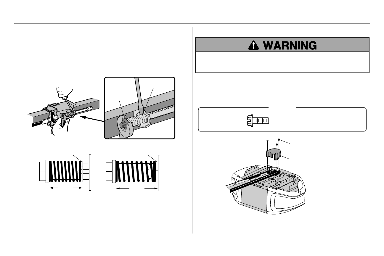
Torsion
Spring
Extension
Spring
OR
Preparation
Safety Symbol and Signal Word Review
This garagedoor opener has been designedandtestedto offer safeservice provided it is installed, operated,
maintained and tested in strict accordancewith theinstructions and warnings containedin this manual.
Whenyou see these Safety Symbols and Signal Words on
the followingpages, they will alert you to the possibility of
Mechanical
serious injury or death if youdo not comply with the
warnings that accompany them.The hazard may come
from somethingmechanical or from electric shock. Read
Electrical
the warnings carefully.
Whenyou see this Signal Word onthe followingpages, it
will alert you to thepossibility of damageto your garage
door and/or the garage door opener if you do notcomply
with thecautionary statements that accompany it. Read
themcarefully.
WARNING: This product can expose youto chemicals including lead, which are known to the State of
California to cause cancer or birth defects or other reproductive harm. For more information go to
www.P65Warnings.ca.gov
Unattended Operation
The Timer-to-Close (TTC) feature, the MyQ®SmartphoneControl app, and MyQ®Garage Door andGate Monitor
are examples of unattendedclose and are to be used ONLY with sectional doors. Anydevice or feature that allows the
door to close without being in the line of sightof the door is considered unattended close. TheTimer-to-Close (TTC)
feature, the MyQ®SmartphoneControl, and any other MyQ®devices are to be usedONLY with sectional doors.
Check the Door
To preventpossible SERIOUSINJURYor DEATH:
l ALWAYScall a trained door systems technician if garage door binds, sticks, or is out ofbalance. An
unbalanced garage door may NOT reverse whenrequired.
l NEVER try to loosen, move or adjust garage door, door springs, cables, pulleys, brackets or their hardware,
ALLof which are under EXTREME tension.
l DisableALLlocks and removeALLropes connected to garage door BEFORE installationandoperating
garagedoor opener to avoid entanglement.
l DO NOT install ona one-piece door if usingdevices or features providingunattended close.Unattended
devices and features are to be used ONLY with sectional doors.
To preventdamageto garage door and opener:
l ALWAYSdisable locks BEFORE installing and operating the opener.
l ONLY operate garage door opener at 120V, 60Hz toavoid malfunction and damage.
Before you begin:
1. Disable locks andremove any ropes connectedto the garage door.
2. Lift the door halfway up. R elease the door. Ifbalanced, it should stay in place,
supportedentirely byits springs.
3. Raise andlower thedoor to check for bindingor sticking. If your door binds,
sticks, or is out ofbalance,call a trained door systems technician.
4. Check theseal on the bottomof the door. Any gap between the floor andthe
bottom of the door must not exceed 1/4 inch (6 mm). Otherwise, the safety
reversal system may not work properly.
5. The opener should beinstalled above the center ofthe door. If there is a torsion
spring or center bearing plate in the way of the header bracket, it may be
installed within 4feet (1.2 m) to the leftor right of the door center. See page 11.
2
Page 3
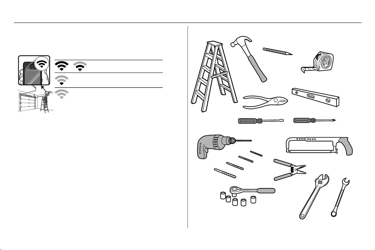
Wi-Fi signal is weak.
The garage door opener will likely connect to your Wi-Fi
network. If not, try one of the options below
.
No Wi-Fi signal. Try one of the following:
• Move your router closer to the garage door opener to
minimize interference from walls and other objects
• Buy a Wi-Fi range extender
• Buy a Chamberlain MyQ® Internet Gateway (CIGBU) see page 41
Check Signal Strength. If you see:
Wi-Fi signal is strong. You’re all set!
Install your new garage door opener.
Visit wifihelp.chamberlain.com for more details
3/16
7/16
1/2
5/32
5/16
3/4
5/8
9/16
1/4
7/16
Preparation
Before You Connect with Your Smartphone
Monitor andcontrol your garagedoor from anywhere usingthe MyQ®app.Youwill need a router with Wi-Fi anda
smartphone or other mobile device. Make sure your mobile device is connectedto your Wi-Fi network. Hold your
mobile device in the place where your garagedoor opener will be installedandcheck the Wi-Fi signal strength.
See MyQ®SmartphoneControl page 33 to connect your garagedoor opener to your Wi-Fi network.
AdditionalItems You May Need:
Survey your garage area to see if you will need any of thefollowing items:
l (2) 2X4Piecesof wood : May be used to fasten the header bracket to the structural supports. Also used to
position the garage door opener during installation and for testingthesafety reversing sensors.
l Support bracket and fastening hardware: Must be usedif you havea finished ceiling in your garage.
l Extension brackets (MODEL 041A5281-1) or wood blocks: Depending upongarageconstruction,
extensionbrackets or woodblocks may beneeded to install the safety reversing sensor.
l Fastening hardware: Alternatefloor mountingof the safety reversing sensor will require hardware not
provided.
l Door reinforcement: Required if you have a lightweight steel, aluminum,fiberglass or glass panel door.
l Rail extension kit: Required if your garagedoor is more than 7 feet(2.13 m) high.
Tools Needed
3
Page 4
Preparation
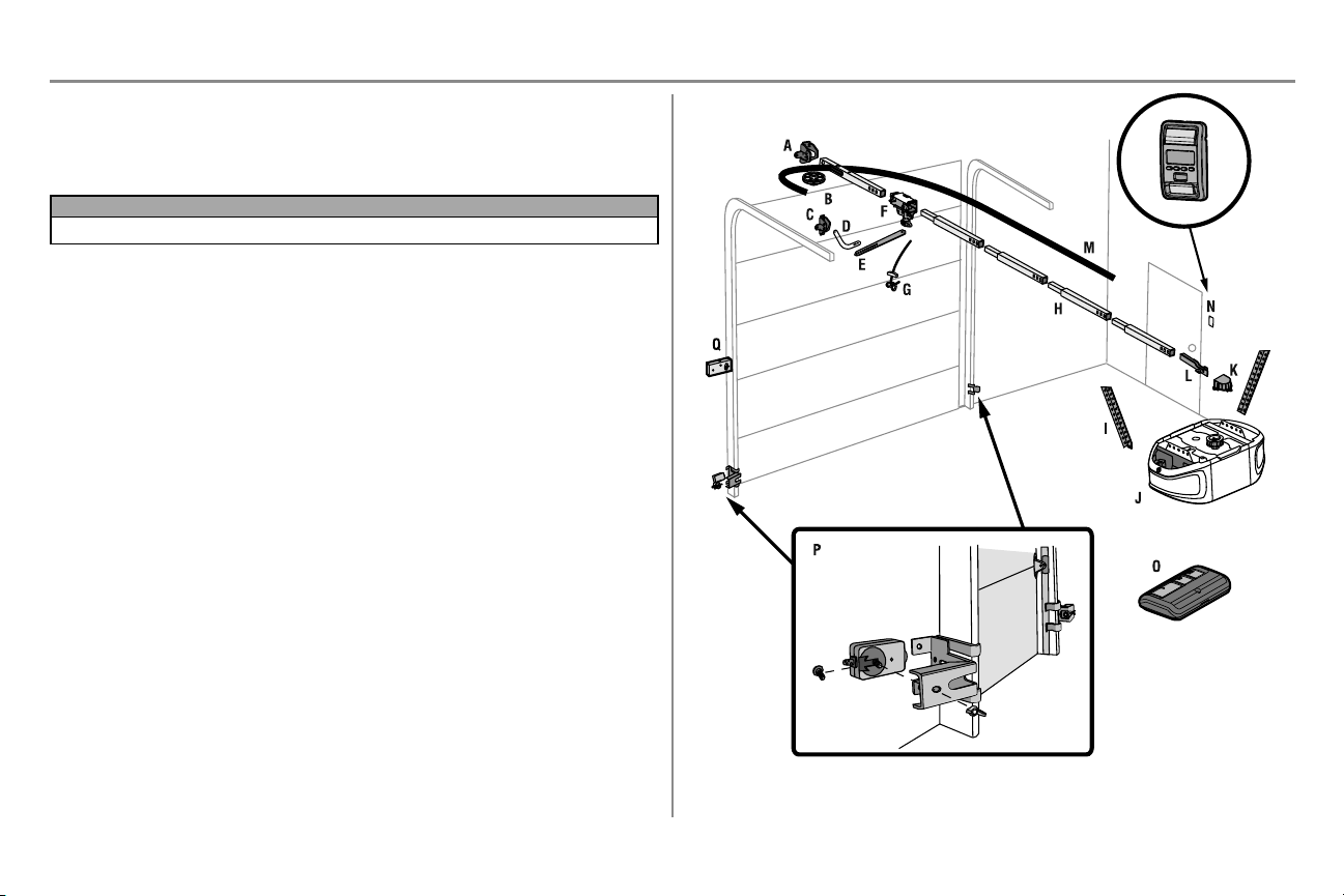
CartonInventory
Save the cartonandpacking material until theinstallation and adjustmentis complete. Instructions for the accessories
will beattached to the accessory and are not includedin this manual. Theimagesthroughout this manual are for
reference only andyour product may look different.
Model Power Door Control Remote Control Wireless Keypad
B980 Max Lift Power System™
A. Header bracket
B. Pulley
C. Door bracket
D. Curved door arm
E. Straight door arm
(Packaged inside frontrail section)
F. Trolley
NOTE: Be sure to assemble the trolley before sliding onto rail.
G. Emergency releaserope and handle
H. Rail (1 frontand4 center sections)
I. Hanging brackets (2)
(Packaged inside thefront rail section)
J. Garage door opener (motor unit)
K. Sprocket cover and screws
L. “U” bracket
M. Belt
N. Door Control
O. Remote control
P. The Protector System
Safetyreversing sensors with 2conductor white and white/black wire attached: Sending Sensor (1),
ReceivingSensor (1), and Safety Sensor Brackets (2)
Q. Automatic GarageDoor Lock
NOT SHOWN
Wireless keypad
White and red/white wire
Owner's manual
Hardware
Smart Control Panel
®
®
3-button(2)
ü
4
Page 5
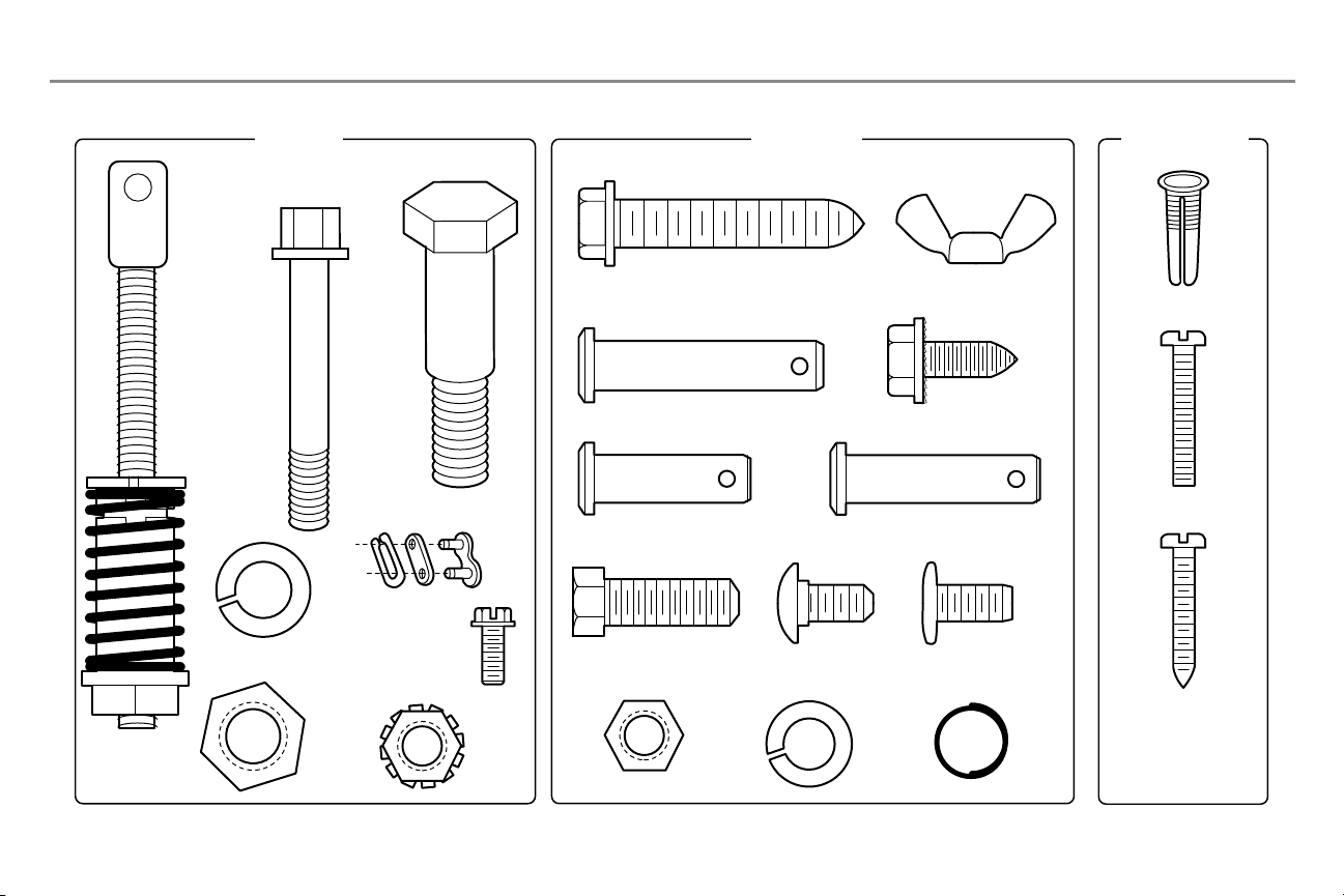
ASSEMBLY INSTALLATION
DOOR CONTROL
Insulated Staples
(N
ot Shown)
Clevis Pin 5/16"x1-1/2"
Ring
Fastener (3)
Hex Bolt 5/16"-18x7/8" (4)
Self-Threading Screw
1/4"-14x5/8" (2)
Clevis Pin 5/16"x1"
Clevis Pin 5/16"x1-1/4"
Carriage Bolt
1/4"-20x1/2" (2)
Screw
1/4"-20x1/2" (2)
Wing Nut
1/4"-20 (2)
Lag Screw 5/16"-9x1-5/8" (4)
Screw 6ABx1" (2)
Drywall Anchors (2)
Screw 6-32x1" (2)
Hex Screw #8x3/8" (3)
(packed with the
sprocket cover)
Bolt
1/4"-20x1-3/4"
Lock Nut
1/4"-20
Bolt
Nut 3/8"
Lock Washer 3/8"
Master Link
Threaded
Shaft with
Spring
Trolley Nut
Lock Washer
5/16"-18 (4)
Nut
5/16"-18 (4)
Preparation
Hardware
5
Page 6
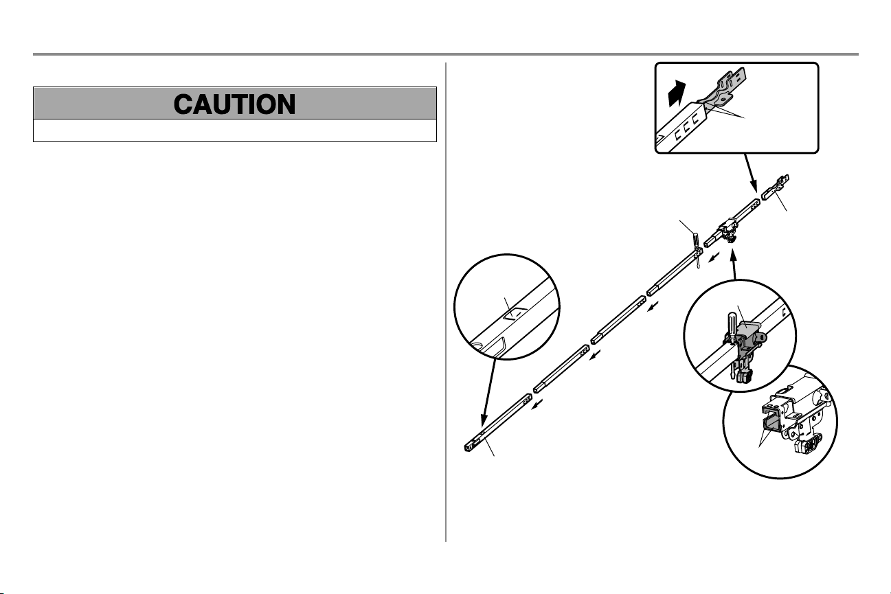
Assembly
Wear Pads
Front Rail Section
(TO DOOR)
“U” Bracket
(TO MOTOR UNIT)
Trolley
Rail Tab
On Top
Slide to stops
on top and sides
of “U” bracket
Screwdriver
STEP 1 Assemble the rail and install the trolley
To preventINJURY frompinching,keep hands and fingers away fromthejoints while assembling the rail.
To avoid installation difficulties, do not run the garage door opener until instructed to do so.
The frontrail has a cut out “w indow” at the door end. The rail tab MUST be on top of therail when assembled.
1. Remove the straightdoor arm andhanging bracket packagedinside the frontrail andset asidefor
Installation Step 5 and 9. NOTE: To prevent INJURY while unpacking the r ail carefully removethe straight
door arm stored within the rail section.
2. Align the rail sectionson a flatsurface as shown and slide the tapered ends intothe larger ones.Tabs
alongthe side will lock into place.
3. Place the motor unit onpacking material toprotect the cover, andrest the back endofthe rail on top. For
convenience, put a support under the frontendof the rail.
4. As atemporary stop,insert a screwdriver into the hole in the second rail section from the motor unit, as
shown.
5. Check tobe sure there are 4plastic wear pads inside the inner trolley. If they becameloose during
shipping, check all packing material. Snap themback intoposition as shown.
6. Slide the trolley assembly toward the screwdriver as shown.
7. Slide the rail onto the “U” bracket, until it reachesall thestops on the top and sides of the “U” bracket.
6
Page 7
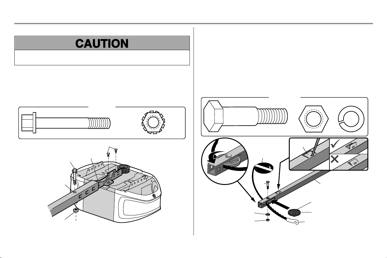
Assembly
Bolt
1/4"-20x1-3/4"
Lock Nut
1/4"-20
HARDWARE
“U” Bracket
Cover Protection
Bolt Hole
Bolt
Lock Nut
Bolts (Mounted in the garage door opener)
Rail
Idler Pulley
Grease Inside Pulley
Bolt
Belt
Lock Washer
Nut
Bolt
Nut 3/8" Lock Washer 3/8"
HARDWARE
Trolley Connector
Rail Tab
STEP 2 Fasten the rail to the motor unit
To avoid SERIOUS damageto garage door opener, use ONLY those bolts/fasteners mountedin the top of the
opener.
1. Insert a 1/4"-20 x 1-3/4" bolt intothe cover protectionbolt hole on theback end of the rail as shown. Tighten
securely with a1/4"-20 lock nut. DO NOT overtighten.
2. Remove the bolts from the top of the motor unit.
3. Use thecarton to support the frontendof the rail.
4. Place the “U” bracket, flat side down onto the motor unit andalign the bracket holes with the bolt holes.
5. Fasten the “U” bracket with the previously removed bolts; D O NOT useany power tools. Theuse of power
tools may permanently damage the garage door opener.
STEP 3 Install the idler pulley
1. Lay the belt besidetherail, as shown. Grasp theendwith thehooked trolley connector and pass
approximately 12" (30 cm) of belt through the window. Keep the ribbed side toward the rail, and allow it to
hanguntil Assembly Step4.
2. Remove the tape from the idler pulley. The inside center should bepre-greased. If dry, regreaseto ensure
proper operation.
3. Place the idler pulley into the window as shown.
4. Insert the idler bolt from the top through the rail and pulley. Tightenwith a 3/8" lock washer and nut
underneaththe rail until thelock washer is compressed.
5. Rotate the pulley to be sure it spins freely.
6. Locatetherail tab. The rail tabis between the idler bolt andthetrolley in the frontrail section. Use a
flathead screwdriver and lift the rail tabuntil thetab is vertical (90º).
7
Page 8
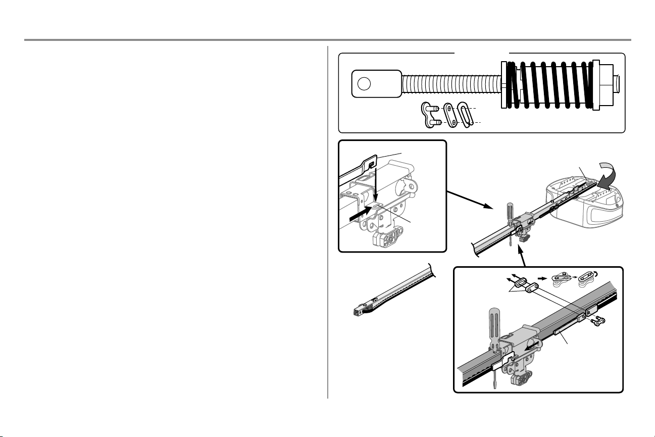
Assembly
HARDWARE
Master Link
Figure 3
Threaded Shaft with Spring Trolley Nut
Threaded Shaft
Master Link
Sprocket
Figure 2
Figure 1
Trolley
Connector
Retaining
Slot
STEP 4 Install the belt
1. Pull thebelt around the idler pulley and toward thetrolley. The ribbedside must contact the pulley.
2. Hook thetrolley connector intothe retaining slot on the trolley as shown (Figure 1).
3. With the trolley against the screwdriver, dispense the remainder of thebelt along the rail lengthtoward the
motor unit and around the sprocket (Figure 2). Thesprocket teeth must engagethe belt.
4. Check tomake sure thebelt is not twisted.Connect the trolley threaded shaft with the master link(Figure
3).
l Push pins ofmaster link bar throughholes in end of belt and trolley threadedshaft.
l Push master link capover pins andpast pin notches.
l Slide the closed end of the clip-on spring over oneof the pins. Pushthe openendof the clip-on spring
ontotheother pin.
5. Remove the spring trolley nut fromthe threadedshaft.
6. Insert the trolley threaded shaft through the hole in the trolley.
8
Page 9
Assembly
Spring
Trolley Nut
Nut Ring Slot
Nut RingNut Ring
AFTER
1-1/4" (3.18 cm)
BEFORE
1" (2.5 cm)
Hex Screw #8x3/8"
(Packed with the sprocket cover)
HARDWARE
Hex Screw
Sprocket Cover
STEP 5 Tighten the belt
1. By hand,thread the springtrolley nut on the threaded shaft until it is finger tightagainstthe trolley. Do not
use any tools. R emovethe screwdriver.
2. Insert a flathead screwdriver tip intooneof the nut ring slots and brace it firmly against the trolley.
3. Tighten the spring trolley nut with an adjustable wrench or a 7/16" open end wrench abouta quarter turn
until the spring releases and snaps the nut ring against the trolley. This sets the spring to optimumbelt
tension.
STEP 6 Install the sprocket cover
To avoid possible SERIOUS INJURY to finger frommoving garage door opener:
l ALWAYSkeephandclear ofsprocket while operating opener.
l Securely attach sprocketcover BEFORE operating.
1. Position the sprocket cover over thesprocket as shown and fasten to the mountingplatewith 8x3/8" hex
screws provided.
You have now finished assembling your garagedoor opener. Please read the following warnings before
proceeding to the installation section.
9
Page 10
Installation
IMPORTANT INSTALLATION INSTRUCTIONS
To reduce the risk of SEVERE INJURY or DEATH:
1. READ AND FOLLOW ALL INSTALLATION WARNINGS AND INSTRUCTIONS.
2. Install garage door opener ONLY on properly balancedandlubricated garage door. Animproperly balanced
door may NOT reverse whenrequired and could result in SEVERE INJUR Y or DEATH.
3. ALL repairs to cables, spring assemblies andother hardware MUST bemade by a trained door systems
technician BEFORE installing opener.
4. Disable ALL locks and remove ALL ropes connectedtogaragedoor BEFORE installing opener to avoid
entanglement.
5. Where possible, install the door opener 7 feet(2.13 m) or more above the floor.
6. Mount the emergency release within reach, but atleast 6 feet (1.83m) above the floor andavoiding contact
with vehicles to avoid accidental release.
7. NEVER connectgaragedoor opener to power source until instructed to doso.
8. NEVER wear watches, rings or loose clothing while installing or servicing opener. They could be caught in
garagedoor or opener mechanisms.
9. Install wall-mountedgaragedoor control:
l within sight of the garage door.
l out of reachof small children ata minimum heightof 5feet (1.5m) above floors, landings, steps or any
other adjacent walking surface.
l away fromALLmoving parts ofthe door.
10. Place entrapment warning label onwall next to garage door control.
11. Place emergency release/safety reverse test label in plain view oninside of garage door.
12. Upon completion of installation,test safety reversal system.Door MUST reverse on contact with a 1-1/2"
(3.8cm) high object (or a 2x4 laid flat) on thefloor.
13. To avoid SERIOUS PERSONAL INJURY or DEATH from electrocution,disconnect ALL electric and battery
power BEFORE performing ANY service or maintenance.
14. DO NOT install ona one-piece door if using devices or features providingunattended close.Unattended
devices and features are to be used ONLY with sectional doors.
10
Page 11
Installation
Header Wall
Vertical Centerline of Garage Door
2x4
Structural
Supports
Level
(Optional)
Unfinished
Ceiling
2x4
OPTIONAL CEILING MOUNT
FOR HEADER BRACKET
Sectional door with curved track
Header Wall
Track
2" (5 cm)
Highest
Point of
Travel
Door
One-piece door with horizontal track
Header Wall
Track
2" (5 cm)
Highest
Point of
Travel
Door
One-piece door without track:
jamb hardware
Header Wall
8" (20
cm)
Highest
Point of
Travel
Door
Jamb
Hardware
One-piece door without track:
pivot hardware
Header Wall
8" (20
cm)
Highest
Point of
Travel
Door
Pivot
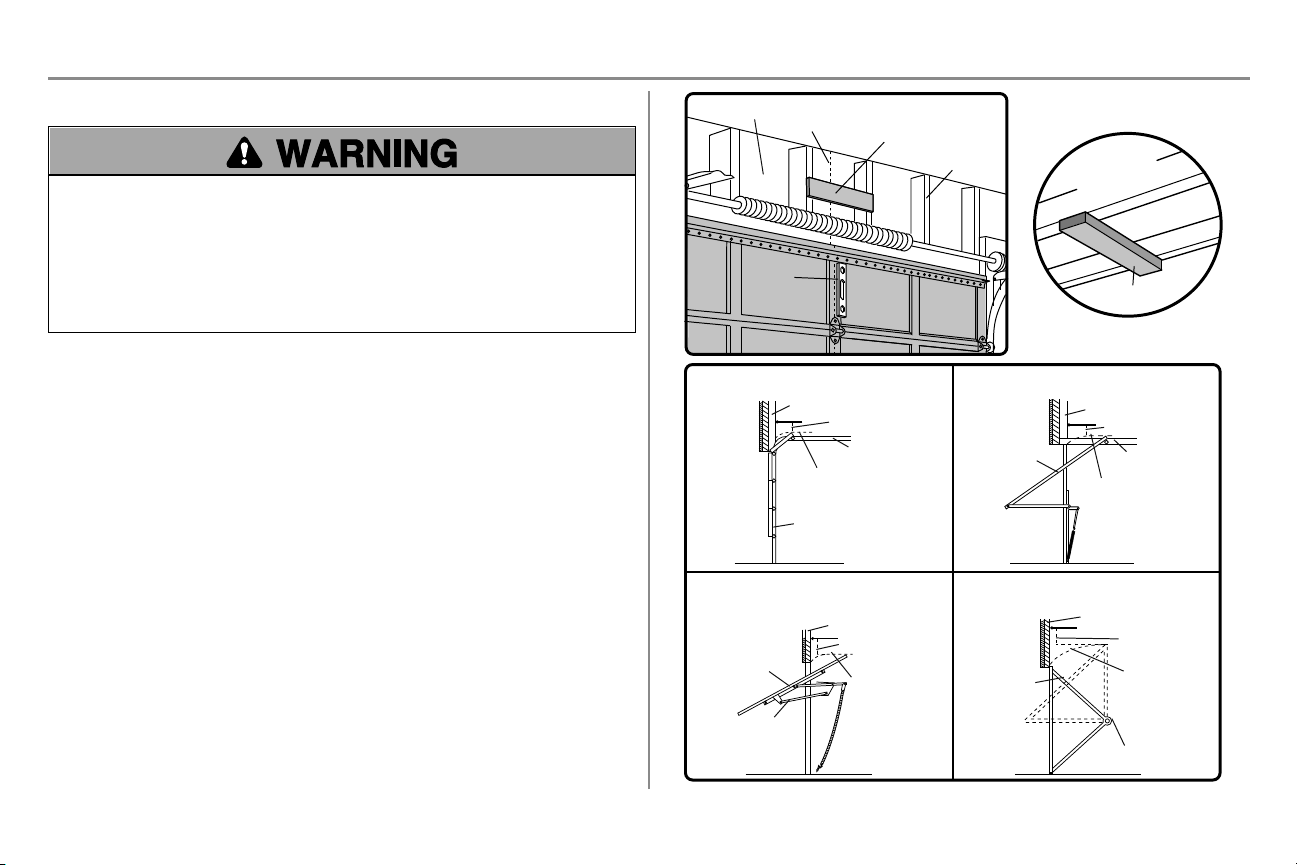
STEP 1 Determine the header bracket location
To preventpossible SERIOUS INJURY or DEATH:
l Header bracket MUST beRIGIDLY fastened to structural support on header wall or ceiling, otherwise
garagedoor might NOT reverse whenrequired. DO NOT install header bracket over drywall.
l Concrete anchors MUST beusedif mountingheader bracketor 2x4into masonry.
l NEVER try to loosen, move or adjust garage door, springs, cables, pulleys, brackets, or their hardware, ALL
of which are under EXTREME tension.
l ALWAYScall a trained door systems technician if garage door binds, sticks, or is out ofbalance. An
unbalanced garage door might NOT reverse whenrequired.
Installation procedures vary accordingto garage door types. Follow theinstructions which apply to your door.
1. Close thedoor and mark theinside vertical centerlineof the garage door.
2. Extendthe line onto the header wall above the door.You can fasten the header bracket within 4 feet (1.22m)
of the left or right of the door center only if a torsion spring or center bearing plate is in the way; or you can
attachit totheceiling (see page 12) whenclearance is minimal. (It may bemountedonthe wall upside
down if necessary, to gainapproximately 1/2" (1 cm). If you need to install the header bracket on a 2x4(on
wall or ceiling), uselag screws (not provided) tosecurely fastenthe2x4 to structural supports as shown
here and on page 12.
3. Open your door tothehighest point of travel as shown. Draw anintersecting horizontal line on the header
wall 2" (5 cm) abovethehigh point:
l 2" (5 cm) abovethe high point for sectional door andone-piece door with track.
l 8" (20 cm) abovethehigh point for one-piece door withouttrack.
This heightwill providetravel clearance for thetopedgeofthe door. N OTE: If the total number of inches exceeds the
height available in your garage, use themaximum height possible, or refer to page 12 for ceiling installation.
11
Page 12
Installation
Lag Screw 5/16"-9x1-5/8"
HARDWARE
UP
Wall Mounting
Holes
WALL INSTALLATION
CEILING INSTALLATION
Optional Mounting
Holes
Vertical
Centerline of
Garage Door
Header Wall
Header
Bracket
2x4
Structural
Support
Door
Spring
Garage Door
Highest Point
of Garage
Door Travel
Horizontal
Line
Lag
Screw
UP
Header Wall
Ceiling Mounting
Holes
Finished Ceiling
Vertical
Centerline of
Garage Door
Header
Bracket
6" (15 cm)
Maximum
Door Spring
Garage Door
Lag Screw
STEP 2 Install the header bracket
You can attach the header bracket either tothewall abovethe garage door, or to the ceiling. Follow the instructions
which will work best for your particular requirements. Do not install the header bracket over drywall. If installing
into masonry, use concrete anchors (not provided).
OPTIONA - WALLINSTALLATION
1. Center the bracket onthe vertical centerlinewith thebottom edgeof the bracket onthe horizontal line as
shown (with thearrow pointingtoward the ceiling).
2. Mark the vertical set of bracket holes. Drill 3/16" pilot holes and fasten the bracket securely to a structural
support with the hardware provided.
OPTIONB - CEILING INSTALLATION
1. Extendthe vertical centerlineontotheceilingas shown.
2. Center the bracket onthe vertical mark, nomore than 6" (15 cm) from the wall. Make sure thearrow is
3. Mark the sideholes. Drill 3/16" pilot holes and fasten bracket securely to a structural support with the
pointingaway fromthewall. The bracket can be mounted flush against the ceiling whenclearance is
minimal.
hardware provided.
12
Page 13
Installation
HARDWARE
Clevis Pin
5/16"x1-1/2"
Ring Fastener
Clevis Pin
Ring Fastener
Connected Disconnected
One-piece door
without tracks
2x4 2x4
All other
door types
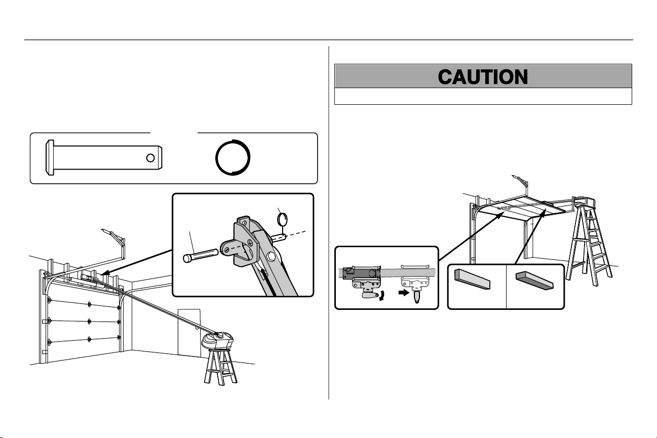
STEP 3 Attach the rail to the header bracket
1. Position the opener on thegaragefloor below the header bracket. Use packing material asa protective
base.
NOTE: If thedoor spring is in the way, you w ill need help. Have someone hold the opener securely on a
temporary support to allow the rail to clear the spring.
2. Position the rail bracket against the header bracket.
3. Align the bracket holes and join with a clevis pin as shown.
4. Insert a ring fastener tosecure.
STEP 4 Positionthe garage door opener
To preventdamageto garage door, rest garage door opener rail on2x4 placed on top sectionof door.
1. Remove the packing material and lift the garage door opener onto a ladder.
2. Fully openthe door and place a 2x4 (laid flat) under the rail. For one-piece doors without tracks, lay the
2x4 on it's side.
NOTE: A 2x4 is ideal for setting the distance between the r ail andthe door. If the ladder is not tall enough you will
needhelp at this point. If the door hits the trolley when it is r aised, pull the trolley release arm down to disconnect the
inner and outer trolley. Slide the outer trolley toward thegaragedoor opener. The trolley can remain disconnected
until instructed.
13
Page 14
Installation
Finished Ceiling
Lag Screw
1
2
3
Not
Provided
Not Provided
Not Provided
Hex Bolt
Nut
Lock
Washer
4 5
6
Lag Screw
Finished Ceiling
EXAMPLES
Unfinished Ceiling
HARDWARE
Hex Bolt
5/16"- 18x7/8"
Nut
5/16"-18
Lock Washer
5/16"-18
Lag Screw
5/16"-9x1-5/8"
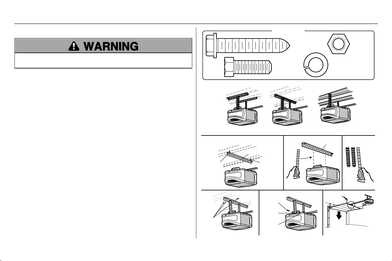
STEP 5 Hang the garage door opener
To avoid possible SERIOUS INJURY from afalling garage door opener, fasten it SECURELY to structural
supports of the garage. Concreteanchors MUST beusedif installing ANY brackets into masonry.
Hanging the garage door opener will vary depending on your garage.Below are three example installations. Your
installation may bedifferent.For ALLinstallations the garage door opener MUST be connectedto structural supports.
The instructions illustrate one of theexamples below.
1. On finishedceilings, usethe lag screws to attach a support bracket (not provided) to thestructural
supports before installing the garage door opener.
2. Make sure thegaragedoor opener is aligned with the header bracket.Measure thedistancefrom each side
of the garage door opener to the support bracket.
3. Cut both pieces ofthehanging bracketto required lengths.
4. Attach the end of each hangingbracket to thesupport bracket with appropriate hardware (not provided).
5. Attach the garage door opener to thehanging brackets with thehex bolts, lock washers, andnuts.
6. Remove the 2x4 and manually close the door. Ifthe door hits the rail, raise the header bracket.
14
Page 15
Installation
or
or
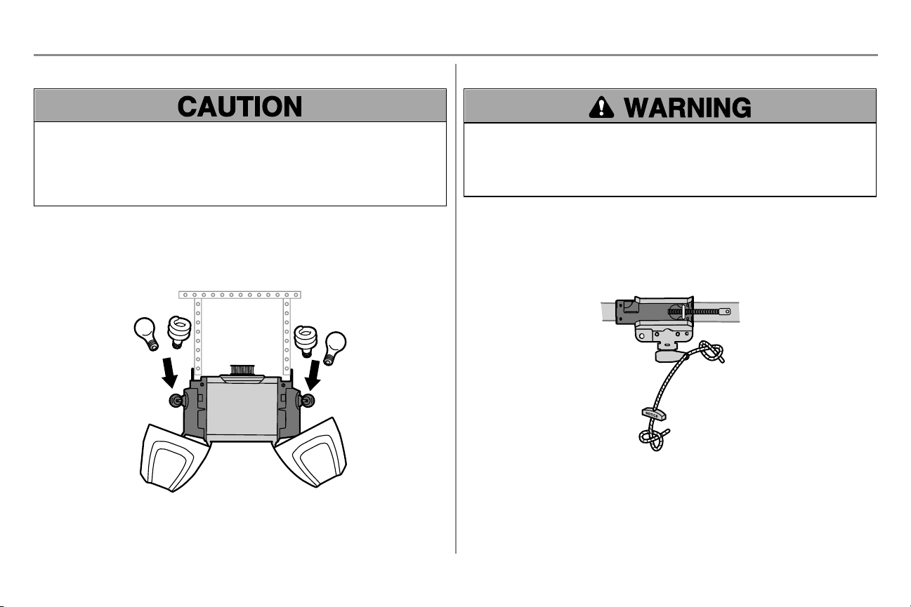
STEP 6 Install the Light Bulbs
To preventpossible OVERHEATING of the end panel or lightsocket:
l Use ONLY A19 incandescent (100W maximum) or compactfluorescent (26W maximum) lightbulbs.
l DO NOT use incandescent bulbs larger than 100W.
l DO NOT use compact fluorescent light bulbs larger than 26W (100Wequivalent).
l DO NOT use halogenbulbs.
l DO NOT use short neck or specialty light bulbs.
1. Pull onthetop sides ofthe lightlens and rotatethelight lens down.
2. Insert an A19incandescent (100W maximum) or compact fluorescent (26W, 100W equivalent) light bulb
into the light socket.
3. Rotate the lens upto close.
NOTE: Do not use halogen,short neck, or specialty light bulbs as these may overheat the end panel or light socket.
Do not use LED bulbs as they may reducethe range or performance of your remote controls.
STEP 7 Attach the emergency release rope andhandle
To preventpossible SERIOUS INJURY or DEATH from afalling garage door:
l If possible, useemergency release handleto disengagetrolley ONLY whengaragedoor is CLOSED. Weak
or brokensprings or unbalanceddoor could result in an open door falling rapidly and/or unexpectedly.
l NEVER use emergency release handle unless garage doorway is clear of persons and obstructions.
l NEVER use handle to pull door open or closed. If ropeknot becomes untied, you could fall.
1. Insert one end of theemergency release rope through the handle. Make sure that “NOTICE” is rightside
up. Secure with an overhand knot at least 1" (2.5 cm) from the end of the ropeto prevent slipping.
2. Insert the other end of theemergency release rope through the hole in the trolley release arm. Mount the
emergency release within reach, but at least 6 feet (1.83 m) abovefloor, avoiding contact with vehicles to
prevent accidental releaseand secure with an overhand knot.
NOTE: If it is necessary to cut the emergency release rope, seal the cut end with a match or lighter toprevent
unraveling. Ensure the emergency release rope and handle are above the top of all vehicles to avoid entanglement.
15
Page 16

Installation
FIGURE 1
FIGURE 3 FIGURE 4
FIGURE 2
Vertical
Reinforcement
Vertical
Centerline
of Garage Door
UP
Door Bracket
Vertical Reinforcement
Vertical Reinforcement
Horizontal Reinforcement
Vertical Centerline
of Garage Door
Hardware
(not provided)
Door Bracket
UP
Vertical
Centerline
of Garage Door
UP
Vertical Centerline of
Garage Door
Hardware
(not provided)
UP
Inside Edge of Door or
Reinforcement Board
Self-Threading Screw
Self-Threading
Screw
HARDWARE
Self-Threading Screw
1/4"-14x5/8"
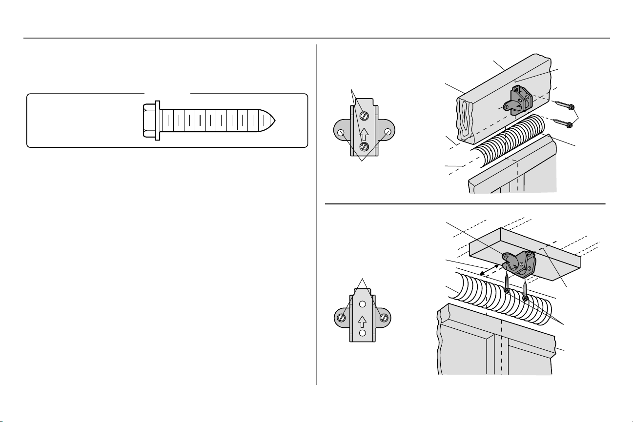
STEP 8 Install the door bracket
Fiberglass, aluminum or lightweight steel garagedoors WILL REQUIRE reinforcementBEFORE installation of
door bracket. Contactthe garage door manufacturer or installing dealer for opener reinforcement instructions or
reinforcementkit. Failure toreinforce the top sectionas required according tothedoor manufacturer may void the
door warranty.
A horizontal and vertical reinforcement is needed for lightweight garage doors (fiberglass, aluminum, steel, doors with
glass panel, etc.) (not provided). A horizontal reinforcement brace should be longenough to be secured to two or three
vertical supports. A vertical reinforcement brace shouldcover theheight of thetoppanel. Contactthe garage door
manufacturer or installingdealer for opener reinforcement instructions or reinforcementkit.
NOTE: Many door reinforcement kits provide for direct attachment of the clevis pin and door arm. In this case you will
not need the door bracket; proceedto the next step.
OPTIONA - SECTIONALDOORS
1. Center the door bracket on the previously marked vertical centerlineused for theheader bracket
installation. Notecorrect UP placement,as stampedinside the bracket.
2. Position the top edge of the bracket 2"-4" (5-10cm) below the top edge of thedoor, OR directly below any
structural support across the topof thedoor.
3. Mark, drill holes and install as follows, dependingon your door’s construction.
Metal or light weight doors using a vertical angle iron bracebetween the door panel support and the door
bracket:
l Drill 3/16" fastening holes. Secure thedoor bracket using thetwo 1/4"-14x5/8" self-threadingscrews.
(Figure1)
l Alternately, use two 5/16"-18x2" bolts, lock washers and nuts (not provided). (Figure2)
Metal,insulated or light weight factory reinforced doors:
l Drill 3/16" fastening holes. Secure thedoor bracket using theself-threadingscrews. (Figure3)
Wood doors:
l Use topandbottom or side to side door bracket holes. Drill 5/16" holes through the door and secure
bracket with 5/16"-18x2" carriage bolts, lock washers and nuts (not provided). (Figure4)
NOTE: The 1/4"-14x5/8" self-threading screws are not intended for use on wood doors.
16
Page 17

Installation
HARDWARE
Self-Threading Screw
1/4"-14x5/8"
For a door with no exposed
framing, or for the optional
installation, use lag screws
5/16"x1-1/2" (not provided)
to fasten the door bracket.
Vertical
Centerline
of Garage
Door
Optional
Placement
of Door
Bracket
Door Bracket
Header Bracket
Header Wall
2x4 Support
(Finished Ceiling)
Door
Bracket
Top of Door
(Inside Garage)
Top Edge of
Door
Optional
Placement
Optional
Placement
Top Edge
of Door
Top of Door
(Inside Garage)
Door
Bracket
Hardware
(not provided)
Hardware
(not provided)
Metal Door Wood Door
Self-Threading Screw
STEP 8 Install the door bracket (continued)
OPTIONB - ONE-PIECE DOORS
1. Center the door bracket on the top of thedoor, in line with the header bracket as shown.
2. Mark either theleft and right,or the topandbottomholes.
Metal Doors:
l Drill 3/16" pilot holes and fasten the bracket with the self-threading screws provided.
Wood Doors:
l Drill 5/16" holes and use 5/16"-18x2" carriage bolts, lock washers and nuts (not provided) or 5/16"x1-1/2"
lag screws (not provided) depending on your installationneeds.
NOTE: The door bracket may be installed on the top edge of the door if required for your installation. (R efer to the
dotted line optional placement drawing.)
17
Page 18

Installation
HARDWARE
Hex Bolt 5/16"-18x7/8"
Nut 5/16"-18
Lock Washer
5/16" -18
Clevis Pin 5/16"x1" Clevis Pin 5/16"x1-1/4"
Ring Fastener
Lock Washer
Nut
Hex Bolt
Clevis Pin
5/16"x1-1/4"
Ring Fastener
Clevis Pin 5/16"x1"
Straight
Door Arm
(Groove
facing out)
Curved
Door Arm
STEP 9 Connect the door arm to the trolley
Installation will vary according to the garage door type.Follow the instructions which apply to your door.
OPTIONA - SECTIONALDOORS
IMPORTANT: The grooveon the straightdoor arm MUST face away from the curveddoor arm.
1. Close thedoor. Disconnectthe trolley by pulling the emergency releasehandle.
2. Attach the straightdoor arm totheouter trolley using theclevis pin. Secure with the ring fastener.
3. Attach the curveddoor arm tothe door bracket using the clevis pin. Secure w ith the ring fastener.
4. Bring arm sections together. Find two pairs of holes that lineup and join sections. Select holes as far apart
as possible to increase door arm rigidity and attach usingthe bolts, nuts, and lock washers.
5. Pull theemergency release handletoward the garage door opener until the trolley releasearm is
horizontal. The trolley will re-engageautomatically when the garage door opener is activated.
NOTE: If theholes in thecurved door arm and the straightdoor arm donot align, reverse the straight door arm, select
two holes ( as far apart as possible) and attach using bolts, nuts, and lock washers. If the str aight door arm is hanging
down too far, you may cut 6 inches (15 cm) from the solid end.
18
Page 19

Installation
HARDWARE
Hex Bolt 5/16"-18x7/8"
Nut 5/16"-18
Lock Washer
5/16" -18
Clevis Pin 5/16"x1" Clevis Pin 5/16"x1-1/4"
Ring Fastener
One-Piece Door without Track
One-Piece Door with Track
Ring Fastener
Ring Fastener
Ring Fastener
Nut
Nut
Ring Fastener
Lock Washer
Lock Washer
Clevis Pin 5/16"x1-1/4"
Clevis Pin
5/16"x1-1/4"
Hex Bolts
Hex Bolts
Clevis Pin
5/16"x1"
Clevis Pin
5/16"x1"
Straight Door Arm
(Groove facing out)
Curved Door Arm
STEP 9 Connect the door arm to the trolley (continued)
OPTIONB - ONE-PIECE DOORS
IMPORTANT: The grooveon the straightdoor arm MUST face away from the curveddoor arm.
1. Close thedoor. Disconnectthe trolley by pulling the emergency releasehandle.
2. Fasten the straight door arm andthecurved door arm together tothe longest possible length (with a2 or 3
hole overlap) using the bolts, nuts, and lock w ashers.
3. Attach the straightdoor arm tothedoor bracket using the clevis pin.Secure with the ring fastener.
4. Attach the curveddoor arm tothe trolley using the clevis pin. Secure with the ring fastener.
5. Pull theemergency release handletoward the garage door opener until the trolley releasearm is
horizontal.
19
Page 20

Installation
Screw
6AB
x1"
(2)
Drywall
Anchors
(2)
Screw
6-32x1"
(2)
HARDWARE
7/16" (11 mm)
Wall
1
2 3
4-5 6
8
7
DRYWALL
GANG BOX
6ABx1"
6-32x1"
Drywall Anchor
DRYWALL GANG BOX
6ABx1"
6-32x1"
Drywall Anchor
STEP 10 Install the door control
To preventpossible SERIOUS INJURY or DEATH from electrocution:
l Be sure power is NOT connectedBEFORE installing door control.
l Connect door control ONLY to 12 VOLT low voltage wires.
To preventpossible SERIOUS INJURY or DEATH from aclosing garage door:
l Install door control within sightof garage door, out ofreach of small children ata minimum height of 5feet
(1.5m) above floors, landings, steps or any other adjacent walking surface, and away from ALL moving parts
of door.
l NEVER permit children to operate or play with door control push buttons or remotecontrol transmitters.
l Activate door ONLY whenit canbe seen clearly, is properly adjusted,andthere are noobstructions to door
travel.
l ALWAYSkeepgaragedoor in sight until completely closed.NEVER permit anyone to cross path of closing
garagedoor.
INTRODUCTION
Older Chamberlain door controls andthird party products are notcompatible. Install thedoor control within sight of the
door at aminimumheight of 5feet(1.5 m) abovefloors, landings, steps or any other adjacent walking surface, where
small children cannot reach, and away fromthemoving parts ofthedoor. For gangbox installations it is not necessary
to drill holesor install the drywall anchors. Use the existing holes in the gang box.
NOTE: Your product may look different than the illustrations.
1. Strip 7/16 inch (11 mm) ofinsulation from one end of the wire andseparatethewires.
2. Connect one wire toeach of the two screws onthe back of thedoor control. The wires canbe connectedto
either screw. If your garage is pre-wired for the door control choose any two wires toconnect,notewhich
wires are used so thecorrect wires are connected to the garage door opener in a later step.
3. Mark the location ofthebottom mounting hole and drill a 5/32inch hole.
4. Install the bottomscrew, allowing 1/8 inch (3 mm) to protrude from thewall.
5. Position the bottom hole of thedoor control over the screw and slide down intoplace.
6. Lift the push bar upandmark the tophole.
7. Remove the door control from the wall and drill a 5/32inch hole for the top screw.
8. Position the bottom hole of thedoor control over the screw and slide down intoplace. Attach the top screw.
20
Page 21

Installation
RED
WHITE
WHITE
GREY
7/16" (11 mm)
2
3
1
HARDWARE
Insulated Staple (Not Shown)
Staple
STEP 11 Wire the door control to the garage door opener
1. Run the white and red/whitewire fromthedoor control to the garage door opener. Attach the wire tothe
wall and ceilingwith thestaple (not applicable for gangbox or pre-wired installations). Do not pierce the
wire with the staple as this may causea short or an open circuit.
2. Strip 7/16 inch (11 mm) ofinsulation from the end of thewire near the garage door opener.
3. Connect the wire tothe red and white terminals onthegaragedoor opener. If your garage is pre-wired
makesure youuse the same wires thatare connectedto the door control. To insert or release wires from
the terminal, push in the tab with screwdriver tip.
STEP 12 Attach the warning labels
1. Attach the entrapment warning label on thewall near the door control with tacks or staples.
2. Attach the manual release/safety reverse test label in a visible location ontheinside of thegaragedoor.
21
Page 22

Installation
Safety Reversing Sensor
6" (15
cm) max. above floor
Invisible Light Beam
Protection Area
Facing the door from inside the garage
Carriage Bolt
1/4"-20 x 1/2"
Wing Nut
1/4"-20
HARDWARE
No more
than 6 inches
(15 cm)
Carriage Bolt
Wing Nut
1
2
3
STEP 13 Install the Protector System
®
Be sure power is NOT connectedto the garage door opener BEFORE installing the safety reversing sensor.
To preventSERIOUS INJURY or DEATH fromclosing garage door:
l Correctly connect and align thesafety reversing sensor. This required safety device MUST NOT be
disabled.
l Install the safety reversing sensor so beamis NO HIGHER than 6" (15 cm) above garage floor.
IMPORTANT INFORMATION ABOUT THE SAFETY REVERSING SENSORS
The safety reversing sensors must be connected and aligned correctly before the garage door opener will
move in the down direction.
The sending sensor (with an amber LED) transmits aninvisible lightbeamto thereceiving sensor (w ith a green
LED). If an obstruction breaks the lightbeamwhile thedoor is closing, the door will stop and reverse to thefull open
position, and the garage door opener lightswill flash 10 times.
NOTE: For energy efficiency the garage door opener will enter sleep mode when the door is fully closed. The sleep
modeshuts the garage door opener down until activated. The sleep mode is sequenced with the garage door opener
light bulb; as the light bulb turns offthe sensor LEDs w ill turn off andw henever thegaragedoor opener lights turn on
the sensor LEDs will light. The garage door opener will not go into thesleep modeuntil the garage door opener has
completed 5 cycles upon power up.
When installing the safety reversing sensors checkthe following:
l Sensors are installed inside the garage, one on either side of thedoor.
l Sensors are facing each other with the lenses alignedandthereceivingsensor lens does not receive direct
sunlight.
l Sensors are no more than 6 inches (15 cm) above the floor and the light beamis unobstructed.
The safety reversing sensors can beattached to the door track, the wall, or the floor. The sensors should be no more
than6 inches (15 cm) abovethefloor. If thedoor track will notsupport thesensor bracket a wall installation is
recommended. Chooseoneof the following installations.
OPTIONA - DOOR TRACKINSTALLATION
1. Slide the curvedarms ofthesensor bracket around the edge of the door track. Snap into place so that the
sensor bracket is flush against the track.
2. Slide the carriage bolt intotheslot oneachsensor.
3. Insert the bolt through the hole in the sensor bracket and attach with the wing nut. The lenses on both
sensors should point toward eachother. Make sure the lens is not obstructed by thesensor bracket.
22
Page 23

Installation
Lens
Carriage
Bolt
(Not provided)
No more than
6 inches (15 cm)
1 2
(Not provided)
Wing Nut
3 4
(Not provided)
I
e
l
l
1 2
Carriage Bolt
Wing Nut
3 4
STEP 13 Install the Protector System®(continued)
OPTIONB - WALLINSTALLATION
If additional clearanceis neededan extension bracket (not provided) or woodblocks canbe used. Make sure each
bracket has thesameamount of clearanceso they will align correctly.
1. Position the sensor bracket against the wall with the curved arms facingthedoor. Make sure there is
enough clearance for the beamto be unobstructed. Mark holes.
2. Drill 3/16inch pilot holes for each sensor bracket and attach the sensor brackets to thewall using lag
screws (not provided).
3. Slide the carriage bolt intotheslot oneachsensor.
4. Insert the bolt through the hole in the sensor bracket and attach with the wing nut. The lenses on both
sensors should point toward eachother. Make sure the lens is not obstructed by thesensor bracket.
OPTIONC - FLOORINSTALLATION
Use anextensionbracket (not provided) or woodblock to raise the sensor bracket if needed.
1. Carefully measure the position of bothsensor brackets so they will be the same distance fromthe wall and
unobstructed.
2. Attach the sensor brackets to thefloor using concreteanchors (notprovided).
3. Slide the carriage bolt intotheslot oneachsensor.
4. Insert the bolt through the hole in the sensor bracket and attach with the wing nut. The lenses on both
sensors should point toward eachother. Make sure the lens is not obstructed by thesensor bracket.
23
Page 24

Installation
Staple
7/16" (11 mm)
WHITE
WHITE
GREY
RED
1
2
3
HARDWARE
Insulated Staple (Not Shown)
STEP 14 Wire the Safety Reversing Sensors
If your garagealready has wires installed for the safety reversing sensors, proceed to page 25.
OPTIONA - INSTALLATION WITHOUTPRE-WIRING
1. Run the wire from both sensors to the garage door opener. Attach the wire tothe wall and ceiling with the
staples.
2. Strip 7/16 inch (11 mm) ofinsulation from each set ofwires. Separate the wires. Twist the white wires
together. Twist thewhite/black wires together.
3. Insert the white wires intothe white terminal on the garage door opener. Insert thewhite/black wires into
the grey terminal onthegaragedoor opener. To insert or remove the wires from the terminal, pushin the
tab with a screwdriver tip.
24
Page 25

Installation
Safety reversing
sensor wires
Pre-installed
wires
White
White/Black
Yellow (for example)
Purple (for example)
Wire nuts (not provided)
Pre-installed wires
Safety reversing
sensor wires
1
3
4
7/16" (11 mm)
2
Purple
Yellow
5
7/16" (11 mm)
Yellow
Purple
To insert or remove the wires from the terminal,
push in the tab with a screwdriver tip.
STEP 14 Wire the Safety Reversing Sensors (continued)
OPTIONB - PRE-WIREDINSTALLATION
1. Cut theend ofthesafety reversing sensor wire, making sure there is enough wire to reach the pre-installed
wires fromthe wall.
2. Separatethesafety reversing sensor wires and strip 7/16 inch (11 mm) of insulationfrom each end.
Choose two of the pre-installed wires and strip 7/16 inch (11 mm) of insulation from each end. Make sure
thatyou choose the samecolor pre-installed wires for each sensor.
3. Connect the pre-installed wires to the sensor wires with wire nuts making sure the colors correspondfor
each sensor. For example, the white wire would connect to the yellow wire andthewhite/black w ire would
connectto the purple wire.
4. At the garage door opener, strip 7/16 inch (11 mm) ofinsulation from each end of the wires previously
chosenfor thesafety reversing sensors. Twist thelike-colored wires together.
5. Insert the wires connected to the white safety sensor wires to the white terminal onthegaragedoor opener.
Insert the wires thatare connectedto the white/black safety sensor wires tothe grey terminal on the garage
door opener.
25
Page 26

Installation
1
2
3
4
5
Approx. 3"
(7.6 cm)
Lock
Terminals
STEP 15 Install the Automatic Garage Door Lock
For use on Residential Garages with an Entry Door Only. Install On Sectional Doors with Torsion
Assemblies Only. Up to two locks canbe installed per compatible garage door opener.
To preventpossible SERIOUS INJURY or DEATH from aclosing gate or door:
l Automatic GarageDoor Lock MUST be installed per theowner’s manual.
l Be sure to DISCONNECT ALLELECTRIC AND BATTERY POWER to the garage door opener BEFORE
installing thegaragedoor lock.
l The door MUST be in the fully opened or closed position BEFORE installing the garage door lock.
l Be sure to DISASSEMBLEandREMOVE any manual door locks that might be currently installed.
UNPLUG THE GARAGE DOOR OPENER AND DISCONNECT THE BATTERY (IF APPLICABLE) BEFORE
PROCEEDING. REMOVE ANY MANUAL LOCKS FROM THE GARAGE DOOR.
1. Attach template(provided) totrack. TIP: The second roller from the bottomis ideal for most installations.
2. Drill holes as markedon template. Use a 3/4" stepdrill bit todrill holes as marked on the template.
OR
If not usinga step drill bit, pre-drill with a smaller drill bit toassure proper placement of the 3/4" hole.
3. Fasten automatic garage door lock to theoutsideof the garage door track with the 1/4"-20x1/2" screws.
4. Run wire (provided) from automatic garage door lock to garagedoor opener. Use insulated staples (not
provided) tosecure wire in several places. N OTE: If you are going to cut the wire you will need to
reconnect wire using a wire nut. D o not tape the ends together. The lock is polarized and requires you
reconnect black to black and white to white wi res.
5. Plug the connector intooneof the lock terminals onthegaragedoor opener. NOT E: To install a second
automatic garage door lock, repeat installation steps on the opposite side of the garage door.
26
Page 27

Installation
Ground Tab
Green Ground Screw
Ground Wire
White Wire
Black Wire
STEP 16 Connect power
To preventpossible SERIOUS INJURY or DEATH from electrocutionor fire:
l Be sure power is NOT connectedto the opener, and disconnect power to circuit BEFORE removingcover to
establish permanentwiring connection.
l Garage door installation and wiring MUST be in compliance with ALL local electrical and building codes.
l NEVER use an extension cord, 2-wire adapter, or change plug in ANY way tomake it fit outlet. Be sure the
opener is grounded.
To avoid installation difficulties, do not run the opener at this time.
To reducethe risk ofelectric shock, your garagedoor opener has agroundingtypeplug with a third grounding pin.
This plug will only fit into a grounding type outlet. If theplug doesn’t fit intothe outlet you have, contact a qualified
electrician to install the proper outlet.
THERE ARE TWO OPTIONS FOR CONNECTING POWER:
OPTIONA - TYPICAL WIRING
1. Plug in the garage door opener intoa groundedoutlet.
2. DO NOT run garage door opener at this time.
OPTIONB - PERMANENT WIRING
If permanent wiring isrequired by your local code, refer to the following procedure. To make a permanent
connection through the 7/8 inch hole in the top of the motor unit (according to local code):
1. Remove the motor unit cover screws and set the cover aside.
2. Remove the attached3-prong cord.
3. Connect the black (line) wire tothe screw onthebrass terminal; the white (neutral) wire to thescrew on
the silver terminal; and the ground wire tothegreen ground screw. The opener must be grounded.
4. Reinstall the cover.
27
Page 28

Installation
Green LED
Amber LED
Wing Nut
SENDING SENSOR
RECEIVING SENSOR
(invisible light beam)
If the receiving sensor is in direct
sunlight, switch it with sending sensor so
it is on the opposite side of the door.
RED
WHITE
GREY
3
2
1
1
2
STEP 17 Aligning the safety reversing sensors
The door will not closeif the sensors have not been installed and aligned correctly.
Whenthelight beam is obstructed or misalignedwhile thedoor is closing,thedoor will reverse andthegaragedoor
opener lights will flash ten times. Ifthe door is already open,it will not close.
1. Check tomake sure theLEDs in both sensors are glowingsteadily. The LEDs in both sensors will glow
steadily if they are aligned and wired correctly.
The sensors can be aligned by looseningthewing nuts, aligningthesensors, and tighteningthe wingnuts.
IF THE AMBER LED ON THE SENDING SENSOR IS NOT GLOWING:
1. Make sure there is power to the garage door opener.
2. Make sure thesensor wire is not shorted/broken.
3. Make sure thesensor has been wired correctly: white wires to white terminal and white/black wires to
grey terminal.
IF THE GREEN LED ON THE RECEIVING SENSOR IS NOT GLOWING:
1. Make sure thesensor wire is not shorted/broken.
2. Make sure thesensors are aligned.
STEP 18 Ensure the door control is wired correctly
If the door control has been installed and wired correctly, a messagewill display on the Smart C ontrol Panel screen.
28
Page 29

Adjustments
UP (Open)
DOWN (Close)
Correct
Incorrect
UP Button
Adjustment
Button
DOWN Button
Actual product may differ from image shown.
PROGRAMMING
BUTTONS
Introduction
Withouta properly installed safety reversal system,persons (particularly small children) couldbe SERIOUSLY
INJURED or KILLED by a closing garage door.
l Incorrect adjustmentof garage door travel limits will interfere with proper operation of safety reversal
system.
l After ANY adjustments are made, the safety reversal system MUST betested.Door MUST reverse on
contactwith1-1/2" (3.8 cm) highobject (or 2x4 laid flat) on floor.
To preventdamageto vehicles, be sure fully opendoor provides adequate clearance.
Your garage door opener is designedwith electronic controls to make setup and adjustments easy. The adjustments
allow you to programwhere the door will stop in theopen(UP) and close (DOWN) position. The electronic controls
sense the amountof force required to open and close the door. The force is adjusted automatically when youprogram
the travel.
NOTE: If anything interferes with the door’s upward travel it will stop. If anything interferes with thedoor’s downward
travel, it will reverse.
One-Piece Doors Only
Whensettingthe UP travel for a one-piece door ensure that the door does not slant backwards when fully open(UP).
If the door is slanted backwards this will causeunnecessary bucking and/or jerking whenthedoor is opening or
closing.
ProgrammingButtons
The programming buttons are located on the left side panel of the garage door opener and are usedto program the
travel. While programming,the UP andDOWN buttons can beused to move the door as needed.
29
Page 30

Adjustments
UP Button
Adjustment
Button
DOWN Button
Actual product may differ from image shown.
PROGRAMMING
BUTTONS
1 2
3
4
5
6 7
STEP 1 Program the Travel
Withouta properly installed safety reversal system,persons (particularly small children) couldbe SERIOUSLY
INJURED or KILLED by a closing garage door.
l Incorrect adjustmentof garage door travel limits will interfere with proper operation of safety reversal
system.
l After ANY adjustments are made, the safety reversal system MUST betested.Door MUST reverse on
contactwith1-1/2" (3.8 cm) highobject (or 2x4 laid flat) on floor.
While programming, the UP and DOWN buttons can beusedto move the door as needed.
1. Press andhold the AdjustmentButton until theUP Button begins to flashand/or a beepis heard.
2. Press andhold the UP Buttonuntil thedoor is in the desiredUP position.
3. Once the door is in the desiredUP position press andrelease the Adjustment Button. Thegaragedoor
opener lights will flash twice and the DOWN Button will begin to flash. IMPORTANT NOTE: For one-
piece door installations refer to page 29.
4. Press andhold the DOWN button until thedoor is in the desired DOWN position.
5. Once the door is in the desiredDOWN position press and release the AdjustmentButton. The garage door
opener lights will flash twice and the UP Button will beginto flash.
6. Press andrelease the UP Button. Whenthe door travels to theprogrammed UP position, the DOWN Button
will begin to flash.
7. Press andrelease the DOWN Button.The door will travel to the programmedDOWN position.
Programmingis complete.
* If thegaragedoor opener lights are flashing5 times during the steps for Program the Travel, the programming has
timedout.If the garage door opener lights are flashing10 times during the steps for Program the Travel, the safety
reversingsensors are misaligned or obstructed (refer to page 28). When the sensors are alignedandunobstructed,
cycle thedoor through a completeup and down cycle using the remote control or the UP and DOWN buttons.
Programmingis complete. If youare unable to operate the door upanddown, repeat the steps for Programming the
Travel.
To watch a video,go to tinyurl.com/lkwbnhj
30
Page 31

Adjustments
1 2
1
2
STEP 2 Test the Safety Reversal System
Withouta properly installed safety reversal system,persons (particularly small children) couldbe SERIOUSLY
INJURED or KILLED by a closing garage door.
l Safetyreversal system MUST be tested every month.
l After ANY adjustments are made, the safety reversal system MUST betested.Door MUST reverse on
contactwith1-1/2" (3.8 cm) highobject (or 2x4 laid flat) on the floor.
1. With the door fully open,place a 1-1/2inch (3.8 cm) board (or a 2x4 laid flat) on the floor, centered under
the garagedoor.
2. Press theremotecontrol push buttonto close the door. Thedoor MUST reverse when it makes contact
with theboard.
If the door stops but does not reverse:
1. Review the installationinstructions providedto insure all steps were followed;
2. Repeat Program the Travel (see Adjustment Step 1);
3. Repeat the Safety Reversal test.
If the test continues to fail, call a traineddoor systems technician.
STEP 3 Test the Protector System
Withouta properly installed safety reversing sensor, persons (particularly small children) could be SERIOUSLY
INJURED or KILLED by a closing garage door.
1. Open the door. Place the garage door opener cartonin the path of the door.
2. Press theremotecontrol push buttonto close the door. Thedoor will not move more than an inch (2.5 cm),
andthe garage door opener lights will flash 10 times.
The garage door opener will not close froma remote control if the LED in either safetyreversing sensor is off (alerting
you to the factthatthe sensor is misalignedor obstructed). If the garage door opener closes the door whenthe safety
reversingsensor is obstructed (andthe sensors are no more than 6inches [15 cm]abovethefloor), call for a trained
door systems technician.
®
31
Page 32

Battery Backup
Battery Status LED
1 2
3
STEP 1 Install the Battery
To reducethe risk ofFIRE or INJURY to persons:
l Disconnect ALL electric andbattery power BEFORE performing ANY service or maintenance.
l Use ONLY Chamberlain part # 41A6357-1 for replacementbattery.
l DO NOT dispose of battery in fire. Battery may explode. Check with local codes for disposal instructions.
ALWAYSwear protective gloves and eye protection whenchanging the battery or working around the battery
compartment.
The battery backup allows access in andoutof your garage, even whenthe power is out. The battery does not have to
be fully charged to operate the garage door opener. When the garage door opener is operating on battery power, it will
run slower andthebattery status LED will glow solid orange, a beep will soundapproximately every 2 seconds. The
following features are unavailable whenoperatingonbattery power:
l Garage Door Opener Lights
l Unattended close devices andfeatures (e.g.MyQ
1. Unplug the garage door opener.
2. Open the lightlens on the right side panel of thegarage door opener. Use a Phillips head screwdriver to
remove the battery cover on thegaragedoor opener.
3. Partially insert thebattery into the battery compartment with the terminals facing out.
4. Connect red (+) and black (-) wires from the garage door opener to thecorresponding terminals onthe
battery.
5. Replace the battery cover.
®
SmartphoneControl andTimer-to-Close)
6. Plug in the garage door opener.
7. Wait for thegreen Battery Status LED to start flashing before proceeding to test thebattery.
STEP 2 Test the Battery
1. Unplug the garage door opener. Thebattery status LED will either glow solid orange indicating opener is
operatingon battery power or will flash indicatinglow battery power. NOTE:Make sure the garage door
opener is unplugged.
2. Open and close thedoor using the remote control or door control. The garage door opener may run slower
if the battery is not fully charged.The battery will take 24 hours tofully charge.
3. Plug in the garage door opener. Verify the battery status LED is flashing green, indicatingthebattery is
charging.
Charge the Battery
The battery chargeswhen the garage door opener is plugged into a 120Vac electrical outlet that has power and
requires 24hours to fully charge.A fully charged battery supplies 12Vdc to thegaragedoor opener for oneto two days
of normal operation duringan electrical power outage. After theelectrical power has been restored,thebattery will
recharge within 24 hours. Thebattery will last approximately 1 to 2 years with normal usage. Instructions for
replacement are provided with the battery. To obtain maximumbattery life and prevent damage, disconnect the battery
when the garage door opener is unplugged for anextended period of time,such as a summer or winter home.
NOTE: When the garage door opener is in battery backup mode the garage door opener lights, Timer-to-Close, and
Remote Close features are unavailable.
In battery backup mode, the Automatic GarageDoor Lock will unlock when the garage door is opened, and will remain
disabled until power is restored.
32
Page 33

MyQ®Smartphone Control
“beep”
LED
Learn
Button
Google Play
App Store
or
Get Connected
…and control your garage door opener with the MyQ®App.
You will need:
l A smartphoneor tablet
l Broadband Internet connection
l A strongWi-Fi signal (2.4 Ghz, 802.11b/g/n required) in the garage, see page3
l Password for your homenetwork
®
l MyQ
serial number locatedonthe garage door opener
1. ACTIVATE "Wi-FiLEARN"MODE
Press andrelease the yellow LEARN buttononthe garage door opener 3 times.The garage door opener will beep
once and a blue light will flash. You have 20 minutes to complete the connectionprocess.
2. CONNECTTO THE MyQ®Wi-FiNETWORK
On your mobile device, go toSettings > Wi-Fi, andselect the network with the "MyQ-" prefix.
3. CONNECTTHEGARAGE DOOR OPENER TO YOURHOME Wi-FiNETWORK
Launch the web browser (such as Safari or Chrome) onyour mobile device andgo to "setup.myqdevice.com". Follow
the on-screenprompts to addthegaragedoor opener to your home Wi-Fi network.
4. SETUP YOURMyQ®ACCOUNT
Download the MyQ®appfrom the App StoreSMor Google Play™ store. Signup for your MyQ®accountandaddthe
MyQ®serial number to your account.
Congratulations you've successfully completed the setup. Enjoy MyQ®Smartphone Control!
In addition to controlling your garagedoor opener you cancontrol your houselighting with additional MyQ
accessories, see page42.
NOTES:
The MyQ®Smartphone Control WILL NOT work if the garage door opener is operating on battery power.
To erase the Wi-Fi settings, see page 38.
®
To learn more go towifihelp.chamberlain.com.
33
Page 34

Operation
IMPORTANT SAFETY INSTRUCTIONS
To reduce the risk of SEVERE INJURY or DEATH:
1. READ AND FOLLOW ALL WARNINGS AND INSTRUCTIONS.
2. ALWAYSkeep remote controls outof reach ofchildren. NEVER permit children to operate or play with garage
door control pushbuttons or remote controls.
3. ONLY activategaragedoor whenit canbe seen clearly, it is properly adjusted, and there are no obstructions
to door travel.
4. ALWAYSkeep garage door in sight and away from people and objects until completely closed. NO ONE
SHOULD CROSS THE PATH OF THE MOVING DOOR.
5. NO ONE SHOULD GO UNDER A STOPPED, PARTIALLY OPENED DOOR.
6. If possible, use emergency release handle to disengagetrolley ONLY whengaragedoor is CLOSED. Use
cautionwhen using this releasewith thedoor open.Weak or broken springs or unbalanceddoor could result in
an opendoor falling rapidly and/or unexpectedly and increasing the risk ofSEVERE INJURY or DEATH.
7. NEVER use emergency releasehandle unless garagedoorway is clear ofpersons and obstructions.
8. NEVER use handle to pull garagedoor open or closed. If ropeknot becomesuntied,you could fall.
9. After ANY adjustments are made,thesafety reversal system MUST betested.
10. Safety reversal system MUST be tested every month. Garage door MUST reverse oncontact with 1-1/2"
(3.8 cm) high object (or a 2x4 laid flat) on thefloor. Failure to adjustthe garage door opener properly
increases therisk of SEVERE INJURY or DEATH .
11. ALWAYS KEEP GARAGE DOOR PROPERLY BALANCED (seepage2). An improperly balanceddoor
may NOT reverse whenrequired and could result in SEVERE INJURY or DEATH.
12. ALLrepairs to cables, spring assemblies and other hardware, ALL of which are under EXTREMEtension,
MUST bemade by a trained door systems technician.
13. ALWAYS disconnect electric and battery power to garage door opener BEFORE making ANY repairs or
removing covers.
14. This operator systemis equippedwith anunattended operation feature. The door could move
unexpectedly. NO ONE SHOULD CROSS THE PATH OF THE MOVING DOOR.
15. DO NOT install ona one-piece door if using devices or features providingunattended close.Unattended
devices and features are to be used ONLY with sectional doors.
16. SAVE THESE INSTRUCTIONS.
34
Page 35

Operation
Manual
release
Using your Garage Door Opener
l The garage door opener can beactivatedwith a wall-mounted door control, remotecontrol, wireless
keyless entry, MyQ®SmartphoneControl appor MyQ®Garage Door Monitor. When the door is closed and
the garagedoor opener is activated the door will open.If the door senses an obstruction or is interrupted
while opening the door will stop. When the door is in any positionother than closed and the garage door
opener is activatedthe door will close. Ifthe garage door opener senses anobstruction while closing, the
door will reverse. If the obstruction interrupts the sensor beamthe garage door opener lights will blink 10
times. If the door is fully open, and the safety reversing sensors are not installed, or are misaligned,the
door will notclose froma remote control, TTC, or the MyQ®SmartphoneControl app. However, youcan
close the door by holding the buttonon the door control or the ENTER button on the keyless entry until the
door is fully closed.
l The garage door opener lightbulbs will turn on whenthe opener is initially plugged in; power is restored
after interruption, or when the garage door opener is activated. The lights will turn off automatically after 41/2 minutes.The lights will turn on whensomeone enters through the opengaragedoor and the safety
reversingsensor infrared beamis obstructed, see page 36. Use an incandescent A19 lightbulb (100W
maximum) or for maximumenergy efficiency a 26W (100W equivalent) compact fluorescent light (CFL)
bulb. NOTE: Do not use halogen, short neck, or specialty light bulbs as these may overheat the end panel
or light socket. D o not use LED bulbs as they may reduce the range or performance of your remote
controls.
To Open the Door Manually
To preventpossible SERIOUS INJURY or DEATH from afalling garage door:
l If possible, useemergency release handleto disengagetrolley ONLY whengaragedoor is CLOSED. Weak
or brokensprings or unbalanceddoor could result in an open door falling rapidly and/or unexpectedly.
l NEVER use emergency release handle unless garage doorway is clear of persons and obstructions.
l NEVER use handle to pull door open or closed. If ropeknot becomes untied, you could fall.
TO MANUALLYDISENGAGE AUTOMATICGARAGE DOORLOCK
1. The door shouldbe fully closed if possible.
2. Disengagethe automatic garage door lock by slidingthe manual releaseto the
openposition.
3. Pull theemergency release handledown and back (toward thegaragedoor
opener). The garage door canthenbe raisedandlowered manually as
necessary.
4. To reconnect the trolley, pull the emergency release handle straight down. The
trolley will reconnect on thenextUP or DOWN operation.
NOTE: The automatic garage door lock w ill re-engage when garage door opener
operationresumes.
DISCONNECTTHETROLLEY
1. The door shouldbe fully closed if possible.
2. Pull down on the emergency releasehandle so the trolley release arm snaps to
the vertical position. The door cannow be raised and lowered as often as
necessary.
TO RE-CONNECTTHE TROLLEY
1. Pull theemergency release handletoward the garage door opener so the
trolley release arm snapsto the horizontal position. The trolley will reconnect
on the next UP or DOWN operation,either manually or by using the door
control or remote control.
35
Page 36

Operation
Push Bar
LIGHT Button
Motion Sensor
Navigation Buttons
Screen
Smart Control Panel
SYNCHRONIZE THE DOOR CONTROL: To synchronize thedoor control to the garage door opener, press the
push bar until thegaragedoor opener activates (it may take upto 3 presses). Test the door control by pressing the
push bar; each press of thepushbar will activate the garage door opener.
PUSH BAR: Press thepush bar toopen or close the door.
LIGHT BUTTON: Press theLIGHT buttonto turn thegarage door opener lights on or off. When the lights are turned
on they will stay on until theLIGHT button is pressed again, or until the garage door opener is activated. Once the
garagedoor opener is activated the lights will turn off after thespecified period oftime (the factory default is 4-1/2
minutes). The LIGHT buttonwill not control thelights whenthe door is in motion.The Light Feature will turn onthe
light on thegaragedoor opener whensomeoneenters through the open garage door and the safety reversing sensor
infrared beam is obstructed.
MOTION SENSOR: The motion sensor automatically turns on the garage door opener lights when motion is detected.
The lights come on for the set period of time, and then shutoff.If using thegaragedoor opener light as awork light
disable the motion sensor, otherwise the lights may turn off automatically if youare beyond the rangeofthe motion
sensor.
NAVIGATION AND SCREEN: The screen displays the time, temperature, and current battery charge(if applicable)
until the menubutton is pressed, and then it will display the menu options. If there is a problemwith thegaragedoors
opener the screen will display an error code(diagnostic code, see page 40). Thefeatures onthedoor control can be
programmed through a series ofmenus on the screen.Use thenavigationbuttons to scroll throughthe menus and
makeselections.
®
MENUOPTIONS
CLOCK SETUP: Set the time; choose 12 or 24 hour clock andshow/hideclock.
TEMPERATURE: Display the temperature in Fahrenheit or Celsius and show/hidethetemperature.
LANGUAGE: SelectEnglish, Spanish or French.
CONTRAST ADJUST: Adjust thescreen contrast.
LIGHT SETTINGS:
To change the amount of timethelights stay on:
1. Select LIGHT SETTINGS fromthe menu.
2. Select LIGHT TIME.
3. Select the timeinterval.
To turn the Light Feature on or off (Factory default is On):
1. Select LIGHT SETTINGS fromthe menu.
2. Select AUTOMATIC LIGHTS.
3. Select ENTRY SENSOR.
To turn the motion sensor onor off:
1. Select LIGHT SETTINGS fromthe menu.
2. Select AUTOMATIC LIGHTS.
3. Select MOTION SENSOR.
LOCK: Prevents the garage door opener from being activated by remotecontrols while still allowing activationfrom
the door control andkeyless entry.
To turn the LOCK feature ON or OFF:
1. Select LOCK from the menu.WhentheLOCK feature is on, a message displays on the screen.
36
Page 37

Operation
1
2 3
OR
PIN
? ?
? ?
4
Press
to continue.
Press
to continue.
MENUOPTIONS (CONTINUED)
TIMER-TO-CLOSE (TTC) (Factory default is set to off): The Timer-to-Close feature automatically closes the
door after aspecified time period and can beadjusted using thedoor control. DO NOT enable TTC if operating a onepiece door. TTC is to be used ONLY with sectional doors. The garage door opener will beepandthe lights will flash
before closing the door. The TTC feature will deactivateif the garage door encounters an obstruction twice; or the
safety reversing sensors are incorrectly installed. Thegaragedoor will reverse open and WILL NOT close until the
obstructions are clear or the safety reversing sensors are correctly installed. When the obstruction has been cleared
or thesafety reversing sensors have been aligned, the door will close when the garage door opener is activated. TTC
WILLNOT work if thegaragedoor opener is operating by battery power or if thesafety reversing sensors are
misaligned.This feature is NOT intendedto be the primary methodof closing the door. A keyless entry should be
installed in the event of anaccidental lock out whenusing this feature.
To turn TTC onor off or to setthe TTC timeinterval:
1. Select TTC from the menu.
2. Select a timeinterval of1, 5, 10minutes or a customsettingup to 99 minutes. Once the TTC has beenset
andthe door is open, a message will display on the screen with the selected time interval.
To temporarily suspend the TTC feature select HOLD. Select REL to resume normal TTC operation.
PROGRAM: Any compatibleremotecontrol, wireless keyless entry, or MyQ®devices canbe programmedto the
garagedoor using the PROGRAM option fromthemenu.
Remote Control and Keyless Entry
Pre-programmed remote control included, no need to program the remote.
To add or reprogram aremotecontrol, follow the instructions below. Older Chamberlain remote controls are NOT
compatible, see page 42 for compatible accessories.
PROGRAMUSINGTHE DOOR CONTROL
1. Press thenavigationbutton below "MENU" to view the Features menu.
2. Use thenavigationbuttons to scroll to "PROGRAM".
3. Select "REMOTE" or "KEYPAD" to programfrom the program menu.
4. Remote Control: Press thebutton on the remote control that you wish tooperateyour garage door.
KeylessEntry: Enter a 4-digit personal identification number (PIN) of your choice on the keyless entry
keypad.Then press theENTER button.
The garage door opener lights will flash (or two clicks will beheard) whenthe code has been programmed. Repeat
the steps for programmingadditional remote controls or keyless entry devices. If programming is unsuccessful, repeat
the steps usingthe learn buttonon the garage door opener.
To watch a video,go to tinyurl.com/lcsf6xt
37
Page 38

Operation
LEARN Button
Adjustment Button
To Erase the Memory
ERASE ALL REMOTE CONTROLS AND KEYLESS ENTRIES
1. Press andhold the LEARN buttonongaragedoor opener until thelearn LED goes out (approximately 6
seconds). All remote control andkeyless entry codes are now erased.Reprogram any accessory youwish
to use.
ERASE ALL REMOTE CONTROLS,KEYLESS ENTRIES ANDMyQ®DEVICES FROM GARAGE
DOOR OPENER
1. Press andhold the LEARN buttonongaragedoor opener until thelearn LED goes out (approximately 6
seconds).
2. Immediately press and hold the LEARN buttonagainuntil the learn LED goes out. All codes are now
erased. Reprogram any accessory youwish to use.
ERASE THE CONNECTIONFROMGARAGE DOOR OPENER TO HOMEWi-FiNETWORK
1. Press andhold the black adjustmentbuttonon thegaragedoor opener until 3 beeps are heard
(Approximately 6 seconds).
ERASE A MyQ®ACCOUNT
1. Go to www.mychamberlain.comto access your MyQ®account.
2. Go to "Account" section.
3. Click "Delete Account".
Go to wifihelp.chamberlain.com for more details.
38
Page 39

Maintenance
1
2
3
Maintenance Schedule
EVERY MONTH
l Manually operate door. If it is unbalancedor binding, call a traineddoor systems technician.
l Check tobe sure door opens and closes fully. Adjust if necessary, see page29.
l Test the safety reversal system.Adjust if necessary, seepage31.
EVERY YEAR
l Oil door rollers, bearings and hinges. Thegaragedoor opener does not require additional lubrication. Do not
grease the door tracks.
l Test the battery backup and consider replacing the battery to ensure the garage door opener will operateduring
an electrical power outage, see page 32 totest the battery backup.
The Remote Control Battery
To preventpossible SERIOUS INJURY or DEATH:
l NEVER allow small children near batteries.
l If battery is swallowed, immediately notify doctor.
To reducerisk of fire, explosionor chemical burn:
l Replace ONLY with 3V CR2032 coin batteries.
l DO NOT recharge, disassemble, heat above 212°F (100°C) or incinerate.
The 3V CR2032 Lithium battery should produce power for upto 3
years. Ifthe battery is low, the remote control’s LED will not flash
when the button is pressed.
To replace battery, pry openthe case first in the middle (1), then at
each side (2 and 3) with thevisor clip. Replace the batteries with only
3V CR2032coin cell batteries. Insert battery positive sideup. Dispose
of old batteries properly.
NOTICE: This device complies with Part 15of the FCC rules andIndustry Canada’s license-exemptRSSs.
Operation is subject to the following two conditions:(1) this device may not causeharmful interference, and (2) this
device must accept any interferencereceived, includinginterference that may cause undesired operation.
Any changes or modifications not expressly approved by theparty responsible for compliance couldvoid the user’s
authority to operate the equipment.
This device must be installed to ensure a minimum20 cm (8 in.) distance is maintainedbetweenusers/bystanders
anddevice.
This device has been tested and foundto comply with the limits for a Class B digital device, pursuantto part 15 of
the FCC rules and Industry CanadaICES standard. These limits are designed to providereasonableprotection
againstharmful interference in a residential installation. This equipmentgenerates, uses andcanradiate radio
frequency energy and, if notinstalled and used in accordance with the instructions, may causeharmful interference
to radio communications.However, there is no guaranteethatinterference will notoccur in a particular installation.
If this equipmentdoes cause harmful interferenceto radioor television reception, which can bedetermined by
turning the equipment off and on, the user is encouraged to try to correct theinterferenceby one or more of the
following measures:
l Reorient or relocate the receiving antenna.
l Increase the separation between the equipmentandreceiver.
l Connect the equipment into anoutlet on acircuit different from that to which the receiver is connected.
l Consult the dealer or an experiencedradio/TV technician for help.
39
Page 40

Troubleshooting
Diagnostic Chart
Your garage door opener is programmedwith self-diagnostic capabilities. The UP and DOWN arrows on the garage door opener flash the diagnostic codes.
DIAGNOSTICCODE SYMPTOM SOLUTION
Up Arrow
Flash(es)
1 1
1 2
1 3
1 4
1 5
1 6
2 1-5
3 2
3 3
4 1-4
4 5
Down Arrow
Flash(es)
The garage door opener will not close and the light bulbs flash.
The garage door opener will not close and the light bulbs flash.
The door control will notfunction.
The garage door opener will not close and the light bulbs flash.
Door moves 6-8" (15-20cm) stops or reverses.
No movement, only a single click.
Opener hums for 1-2 seconds no movement.
Door coasts after it has cometo a complete stop. Program travel to coasting positionor have door balanced by atrained door systems technician.
No movement, or sound. Replace logic board.
Unable to setthe travel or retain position. Check travel module for proper assembly, replace if necessary.
The battery status LED is constantly flashing green. Battery backup charging circuit error, replace the logic board.
Door is moving stops or reverses. Manually open and close thedoor. Check for binding or obstructions, suchas a broken springor door lock, correct as
Opener runs approximately 6-8" (15-20cm), stops and reverses. Communicationerror to travel module. Check travel module connections, replacetravel module if necessary.
Safetyreversing sensors are not installed,connected, or wires may becut. Inspect sensor wires for a disconnected
or cutwire.
There is a short or reversedwire for the safety reversing sensors. Inspect safety sensor wire at all staple and
connectionpoints,replace wire or correct as needed.
The wires for the door control are shortedor thedoor control is faulty. Inspect door control wires at all staple and
connectionpoints,replace wire or correct as needed.
Safetyreversing sensors are misaligned or were momentarily obstructed. Realign both sensors to ensure both LEDs
are steady and not flickering. Make sure nothing is hangingor mountedon the door that would interruptthe sensor’s
pathwhile closing.
Manually open and close thedoor. Check for binding or obstructions, suchas a broken springor door lock, correct as
needed.Check wiring connections at travel module and at the logic board. Replacetravel module if necessary.
Manually open and close thedoor. Check for binding or obstructions, suchas a broken springor door lock, correct as
needed.Replace logic board if necessary.
Manually open and close thedoor. Check for binding or obstructions, suchas a broken springor door lock, correct as
needed.Replace motor if necessary.
needed.If the door is binding or sticking contact a traineddoor systems technician. If door is not binding or sticking
attempt to reprogramtravel (refer topage30).
40
Page 41

Battery Status LED
Troubleshooting
DIAGNOSTICCODE SYMPTOM SOLUTION
Up Arrow
Flash(es)
4 6
The garage door opener can beep for severalreasons:
l Operating on battery power or the 12Vdc battery needs to bereplaced, see page 32.
l Garage door opener has been activated through a device or feature such as Timer-to-Close or garagedoor
monitor, seepage37.
My remote control willnot activate the garage door:
l Verify thelock feature is not activated on the door control.
l Reprogram the remote control.
l If the remote control will still not activate thedoor check the diagnostic codes to ensurethe garage door opener
is workingproperly.
My door will not close and the light bulbs blink on my motor unit:
The safety reversing sensor must be connectedandalignedcorrectly before the garage door opener will movein the
down direction.
l Verify thesafety reversing sensors are properly installed, aligned and freeof any obstructions.
My garage door opener light(s) willnot turn off when the door is open:
The garage door opener is equipped with a feature that turns thelight on whenthe safety reversing sensors have been
obstructedor whenthe motionsensor onthedoor control detects movementin the garage. Thesefeatures canbe
disabled using the door control, seepage36.
Wi-Fi troubleshooting
The garage door opener will NOT enter Wi-Fi LEARN mode:
l After the initial installationof the garage door opener, the garage door opener must complete a full cycle (open
andclosed) before the Wi-Fi LEARN mode can beactivated.
l If there has been a recent power outage,thegaragedoor opener must complete a full cycle before the Wi-Fi
LEARN mode can be activated.
See page33 to activateWi-Fi LEARN mode.
If your black adjustment button is notsolid greengo to wifihelp.chamberlain.com.
Down Arrow
Flash(es)
The garage door opener will not close and the light bulbs flash. Safetyreversing sensors are misaligned or were momentarily obstructed. Realign both sensors to ensure both
LEDs are steady and not flickering.Makesure nothingis hanging or mountedonthe door that would interruptthe
sensor’s pathwhile closing.
My vehicle'sHomelink®is not programming to my garage door opener:
Compatibility BridgeTM(not included) may be necessary for certain vehicles. Visit bridge.chamberlain.com to findout if
a Bridgeis needed.
My neighbor’s remote control opens my garage door:
Erase the memory fromyour garage door opener and reprogramthe remote control(s).
Green battery status LED - All systems are normal:
l A solid green LED light indicatesthe battery is fully charged.
l A flashing greenLED indicates the battery is being charged.
Orange battery status LED - The garagedoor opener has lost power and isin battery backup mode:
l A solid orange LED with beep, soundingapproximately every 2 seconds, indicates the garage door opener is
operatingon battery power.
l A flashing orange LED with beep, soundingevery 30seconds,indicates the battery is low.
Red battery status LED - The garage door opener's 12V battery needs to be replaced:
l A solid redLED with beep, soundingevery 30seconds, indicates the 12V battery will no longer hold a charge and
needs to bereplaced. Please call for replacement battery to allow your systemto operate during a power outage.
41
Page 42

Accessories
CLOSED
8808CB
8810CB
8 Foot (2.4 m) Rail Extension:
To allow an 8 foot (2.4 m)
door to open fully.
10 Foot (3 m) Rail Extension:
To allow a 10 foot (3 m) door
to open fully.
041A5281-1
CLLP1
Extension Brackets:
(Optional) For safety reversing
sensor installation onto the
wall or fl oor.
Laser Parking Assistant:
Park in the right spot every
time! A laser beam is activated
by your
garage door opener and
projected on to the dashboard
of your vehicle to guide perfect
parking.
MyQ® Accessories
You can program up to 10 MyQ® accessories to your MyQ® account.
PILCEV MyQ® Remote Lamp Control:
Monitor and control this plug
in lamp switch with the MyQ®
Smartphone App.
WSLCEV MyQ® Interior/Exterior Light
Switch
Monitor and control this wall
light switch with the MyQ®
Smartphone App.
953EV
940EV Wireless Keypad:
CIGBU
42
Remote Control:
Works with ALL Chamberlain
openers from 1993-present.
®
compatible. Includes
MyQ
visor clip.
For use outside of the home
to enable access to the garage
using a 4-digit PIN. Works
with ALL Chamberlain openers
from 1993-present. MyQ®
compatible.
MyQ® Internet Gateway:
Offers longer range wireless
signal than standard Wi-Fi.
Plugs into your home router
as an optional way to provide
MyQ® Smartphone Control for
your garage door opener and
MyQ® light controls.
956EV Keychain Remote Control:
Works with ALL Chamberlain
openers from 1993-present.
MyQ® compatible. With key
ring.
41A6357-1 Standby Power System
Battery:
Provides backup power to the
garage door opener.
Page 43

Warranty
This garage door opener WILL NOT work until the
safety reversing sensors are properly installed and aligned.
Contact Information
For installation and service information call:
1-800-528-9131
Before calling, please have the model number of the garage door opener.
If you are calling about a Troubleshooting issue, it is recommended that you have access to your
garage door opener while calling.
If you are ordering a repair part please have the following information:
part number, part name, and model number.
STOP!
The Chamberlain Group, Inc.® (“Seller”) warrants to the fi rst retail purchaser of this product, for the residence
in which this product is originally installed, that it is free from defects in materials and/or workmanship for a
specifi c period of time as defi ned below (the “Warranty Period”). The warranty period commences from the
date of purchase.
Parts Motor Accessories Belt Battery Backup
5 Years Lifetime 1 year Lifetime 1 year
The proper operation of this product is dependent on your compliance with the instructions regarding
installation, operation, and maintenance and testing. Failure to comply strictly with those instructions will void
this limited warranty in its entirety. If, during the limited warranty period, this product appears to contain a
defect covered by this limited warranty, call 1-800-528-9131, toll free, before dismantling this product. You
will be advised of disassembly and shipping instructions when you call. Then send the product or component,
pre-paid and insured, as directed to our service center for warranty repair. Please include a brief description
of the problem and a dated proof- of-purchase receipt with any product returned for warranty repair. Products
returned to Seller for warranty repair, which upon receipt by Seller are confi rmed to be defective and covered
by this limited warranty, will be repaired or replaced (at Seller’s sole option) at no cost to you and returned
pre-paid. Defective parts will be repaired or replaced with new or factory rebuilt parts at Seller’s sole option.
[You are responsible for any costs incurred in removing and/or reinstalling the product or any component .]
ALL IMPLIED WARRANTIES FOR THE PRODUCT, INCLUDING BUT NOT LIMITED TO ANY IMPLIED
WARRANTIES OF MERCHANTABILITY AND FITNESS FOR A PARTICULAR PURPOSE, ARE LIMITED IN
DURATION TO THE APPLICABLE LIMITED WARRANTY PERIOD SET FORTH ABOVE FOR THE RELATED
COMPONENT(S), AND NO IMPLIED WARRANTIES WILL EXIST OR APPLY AFTER SUCH PERIOD. Some
States and Provinces do not allow limitations on how long an implied warranty lasts, so the above
limitation may not apply to you. THIS LIMITED WARRANTY DOES NOT COVER NON-DEFECT DAMAGE,
DAMAGE CAUSED BY IMPROPER INSTALLATION, OPERATION OR CARE (INCLUDING, BUT NOT LIMITED TO
ABUSE, MISUSE, FAILURE TO PROVIDE REASONABLE AND NECESSARY MAINTENANCE, UNAUTHORIZED
REPAIRS OR ANY ALTERATIONS TO THIS PRODUCT), LABOR CHARGES FOR REINSTALLING A REPAIRED
OR REPLACED UNIT, REPLACEMENT OF CONSUMABLE ITEMS (E.G., BATTERIES IN REMOTE CONTROL
TRANSMITTERS AND LIGHT BULBS), OR UNITS INSTALLED FOR NON-RESIDENTIAL USE. THIS LIMITED
WARRANTY DOES NOT COVER ANY PROBLEMS WITH, OR RELATING TO, THE GARAGE DOOR OR GARAGE
DOOR HARDWARE, INCLUDING BUT NOT LIMITED TO THE DOOR SPRINGS, DOOR ROLLERS, DOOR
ALIGNMENT OR HINGES. THIS LIMITED WARRANTY ALSO DOES NOT COVER ANY PROBLEMS CAUSED
BY INTERFERENCE. UNDER NO CIRCUMSTANCES SHALL SELLER BE LIABLE FOR CONSEQUENTIAL,
INCIDENTAL OR SPECIAL DAMAGES ARISING IN CONNECTION WITH USE, OR INABILITY TO USE,
THIS PRODUCT. IN NO EVENT SHALL SELLER’S LIABILITY FOR BREACH OF WARRANTY, BREACH OF
CONTRACT, NEGLIGENCE OR STRICT LIABILITY EXCEED THE COST OF THE PRODUCT COVERED HEREBY.
NO PERSON IS AUTHORIZED TO ASSUME FOR US ANY OTHER LIABILITY IN CONNECTION WITH THE SALE
OF THIS PRODUCT.
Some states and provinces do not allow the exclusion or limitation of consequential, incidental or special
damages, so the above limitation or exclusion may not apply to you. This limited warranty gives you specifi c
legal rights, and you may also have other rights, which vary from state to state and province to province.
CHAMBERLAIN® LIMITED WARRANTY
WARRANTY PERIOD
43
Page 44

Automatic Garage Door Opener Safety & Maintenance Guide
Garage Door Opener Safety – An Automatic Decision
A garage door isthe largest moving object in the home. An improperly adjusted garage door and opener can exert deadlyforce when the door closes– which could lead to entrapment of children or adults and
subsequent injury or death.
Proper installation, operation,maintenance, and testing ofthegaragedoor and automatic opener are necessary to provide a safe, trouble-freesystem. Careless operation or allowing childrento play with or use garage door opener controls are
also dangerous situations that can leadto tragic results. A few simple precautions can protectyour family andfriends frompotential harm. Pleasereview the safety and maintenance tips in this guide carefully and keep it for reference.Check
the operationof your garagedoor and opener to ensure they function in a safe and trouble-free manner. Be sure to readall Important Safety Informationfound in your garage door opener’s manual as it provides more details andsafety
considerations than can be supplied w ith this guide.
Garage Door Openers are Not Toys
Discuss garage door andopener safety with your children. Explain the danger of being trapped under the door.
Stay away from a moving door. The wall-mounted push button should be out of reach of
Keep transmitters and remote controls out of reach of children.
Do not letchildren play with or use transmitters or other remote control
devices.
44
children, atleast 5 feet from the nearest standing surface andaway
from all moving parts. Mountanduse the buttonwhere youcan clearly
see the closing garage door.
Keep the door in sight until it completely closes whenusing the
wall-mountedpush buttonor transmitter.
Page 45

Routine Maintenance Can Prevent Tragedies
1
2
Makemonthly inspectionandtesting of your garagedoor and opener systema part ofyour regular routine. Review your owner’s manual for boththedoor and door opener. If youdon’t have the owner’s manuals, contact the manufacturer(s)
andrequest a copy for your specific model(s). Look for the opener model number onthe back of thepower unit.
WARNING – Springs are under high tension.Onlyqualifiedindividuals shouldadjust them.
Visuallycheckthe door and installation:
l Starting with the door in the closedposition, use the manual disconnect on theopener to disconnect the door.
l Look for signs of wear or damage on hinges, rollers, springs, and door panels.
l These parts may require periodic lubrication. Check theowner’s manual for suggested maintenance.
l If any signs of damageare evident, contact a traineddoor systemstechnician for assistance.
l Verify thephotoeye heightis no higher than 6" from the garage floor.
Test the door for proper operation:
l Openandclose thedoor manually usinghandles or suitable grippingpoints.
l The door should move freely and withoutdifficulty.
l The door should balanceand stay partially open 3–4 feet abovethe floor.
l If you detect any signs of improper operation, contact a traineddoor systems technician for assistance.
Test the opener safety features:
l Reconnect the opener to the door using the manual disconnect and open the door.
l Place a 2x4 board flat in the path of the door (1) and try to close it (2). The door should stopwhen it comesin contact with the 2x4 and
thenreverse direction.
l Block thephotoelectric sensor by waving an object in front ofthesensor and attempt to close the door. The door should not close
unless the wall-mountedpush buttonis manually held duringoperation.
l If the opener does not perform as described, contact a trained door systems technician for assistance.
45
Page 46

Repair Parts
Rail Assembly Parts
Description Part Number
1 Belt 041A5250
2 Pulley K144C0054
3 Master Link 004A1008
4 Rail 041A5665
5 Trolley Assembly
(Includes: Threaded
Shaft (1), Clevis Pin (1),
Ring (1))
6 “U” Bracket 041D0598-1
Not Shown
Wear Pads 041A7276
Hardware Bag 041A7920-2
041C5141-2
Accessories
Description Part Number
1 Smart Control Panel® 041A7305-1
2 Remote Control 953ESTD
3 Automatic Garage
Door Lock
841CB
Installation Parts
2
1
Description Part Number
3
1 Curved Door Arm 041B0035B
2 Door Bracket with Clevis
Pin and Fastener
3 Emergency Release Rope
3
and Handle
4 Header Bracket with
041A5047-1
041A2828
041A5047-2
NOTICE
11
Clevis Pin and Fastener
5 Remote Control
4
5
6
Visor Clip
6 Safety Sensor Bracket 041A5266-3
7 Safety Sensor Kit
Receiving and sending
K29B0137
041A5034
sensors with wire
8 Straight Door Arm 4178B0034B
9 White and Red/White Wire 041B4494-1
1
10 3V CR2032 Lithium
Battery
K010A0020
8
11 Hanging Brackets 012B0776
2
Not Shown
Owner’s Manual 114A5036
3
2
1
4
7
6
9
5
10
46
Page 47

Repair Parts
Garage Door Opener Parts
3
8
4
Description Part Number
1 Sprocket and Sprocket Cover with Screws 041C1751
2 End Panel with light socket 041D7639-1
3 Light Lens 041D7572
4 Light Socket 041C0279
1
11
12
9
6
5
2
7
4
10
5 Transformer 041D0277-1
6 Cover 041D9137
7 Motor with Travel Module 041D8006-1
8 End Panel for Receiver Logic Board with light socket 041D9242
9 Receiver Logic Board 050DCTWFLK
10 Travel Module 041D8071-4
11 Line Cord 041B4245-1
3
12 Terminal Block 041A3150
Not Shown
Wire Harness 041D8255
47
Page 48

© 2018, The Chamberlain Group, Inc.
All Rights Reserved
Wi-Fi
App Store is a service mark of Apple Inc.
®
is a registered trademark of Wi-Fi Alliance
114A5126 Google Play is a trademark of Google Inc.
The Chamberlain Group, Inc.
300 Windsor Drive
Oak Brook, IL 60523
 Loading...