

Page 1
20.1” LCD TV Service Manual
T F T L C D T V & M O N I T O R
T F T L C D T V & M O N I T O R
20.1” LCD TV Service Manual
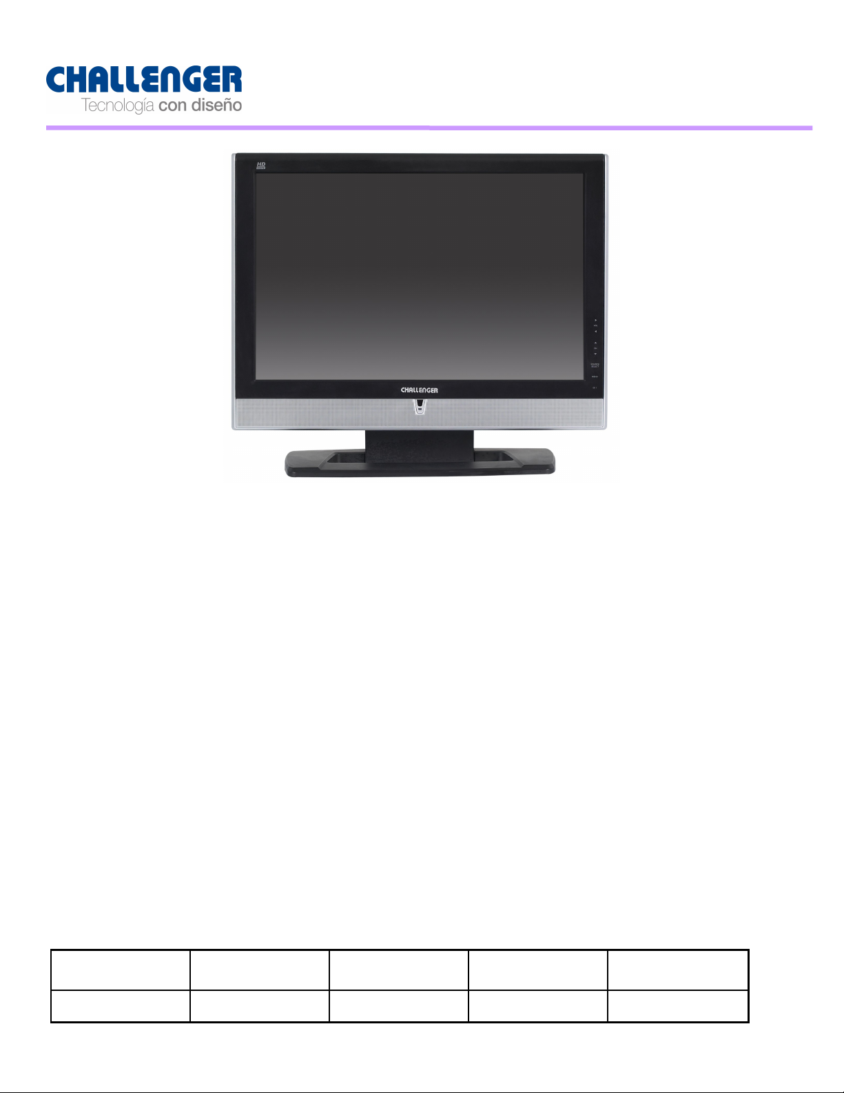
LT-2041BPE
M O D EL NA M E
LT- 204 1 B P E RD(1) 00 06/ 1 1 / 13 1 /22
D O C U M E N T
N O
REVIS I O N N O
REVIS I O N
DATE
PA GE
Page 2
20.1” LCD TV Service Manual
20.1” LCD TV Service Manual
M O D E L NA M E
LT- 204 1 B P E RD(1) 00 06/ 1 1 / 13 2/22
D O C U M E N T
N O
REVIS I O N N O
REVIS I O N
DATE
PA GE
Page 3
20.1” LCD TV Service Manual
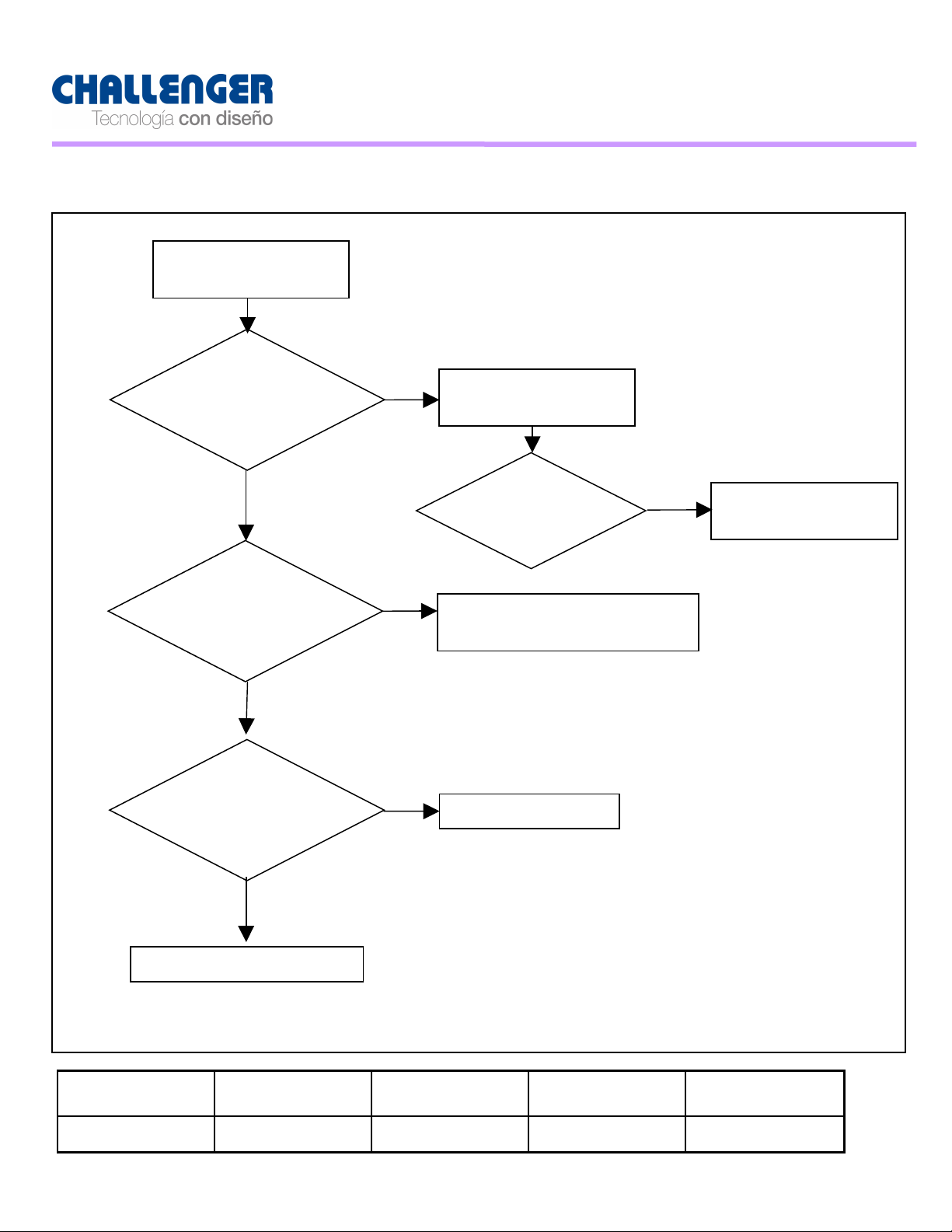
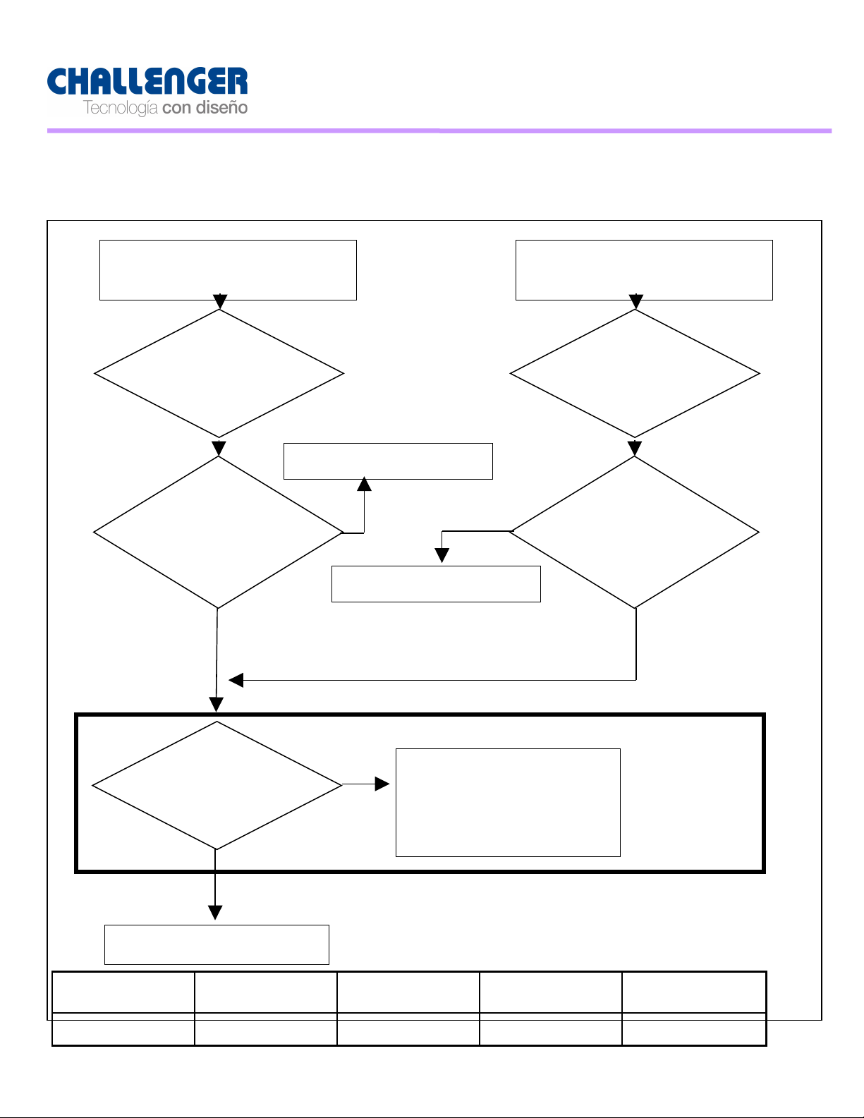
:[A ]
N o Pow er
Check 5V,ST _ 5V,
1 2V, of Pow er
Check output of
I C 1 05, I C 1 03
Check P1 1 0
Check LE D
N o Pow er
Pas
Check O utput of
Change
Fai l
Pas
Change I C1 05,
Fai l
Fai l
Change LED
Fai l
20.1” LCD TV Service Manual
◈ T R O U B L E S H O O T I N G
M O D E L NA M E
LT- 204 1 B P E RD(1) 00 06/ 1 1 / 13 3/22
D O C U M E N T
N O
< 1 >
REVIS I O N N O
REVIS I O N
DATE
PA GE
Page 4

20.1” LCD TV Service Manual
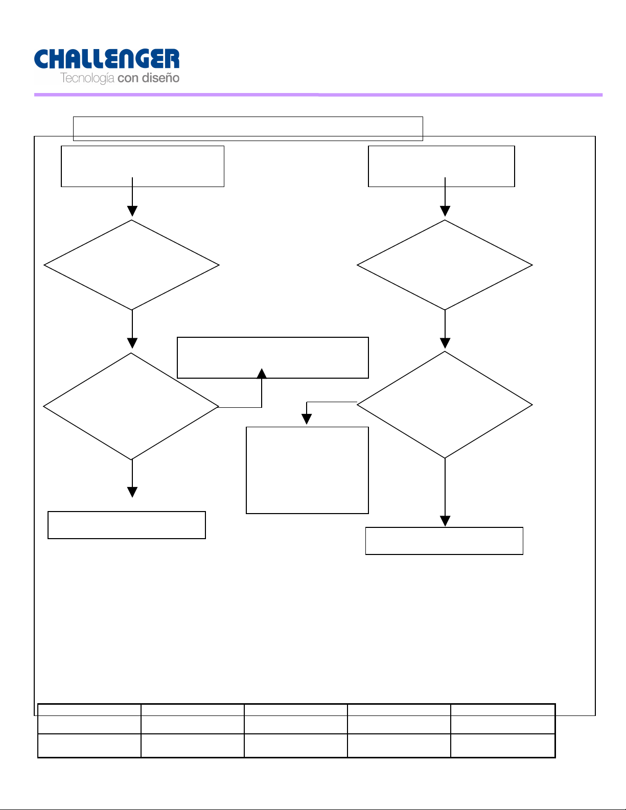
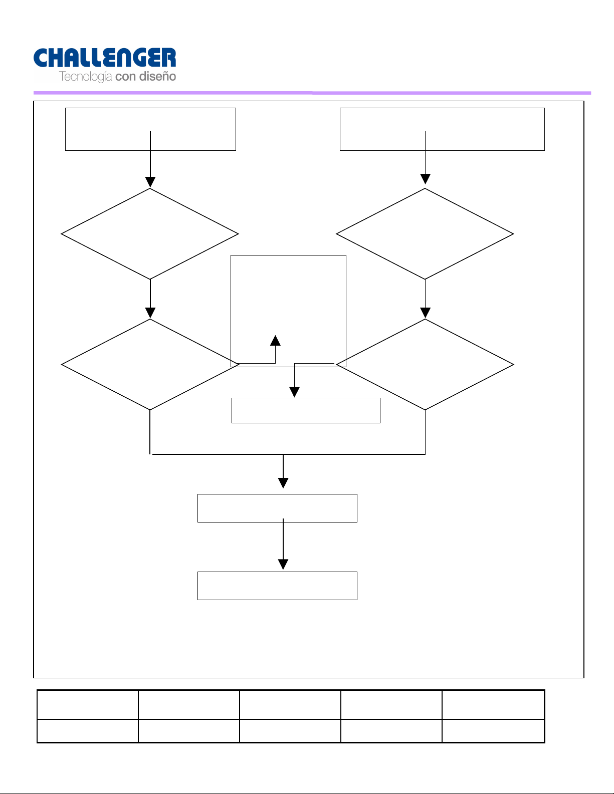
No Raster on Co mponent
Change the defect
part Check
Check input source cable and jack = > L V D S
LVDS
cable
Change the defect
Re-soldering or Change
the defect part Check
I C 1 0 1 , I C 1 02,I C20 1 ,P 1 0
20.1” LCD TV Service Manual
Repeat [A]Process
Pass
Check the
R0 13,R 0 15, R0 18
Pass
Check the input/
output of I C 00 1
Pass
Check the signal of
P30 1 or LVDS cable
Pass
Pass
Fail
Fail
Fail
Re-soldering or
:[ C ] Pr oces s
Re-soldering or
Change P30 1 ,
Check T M D S Assy
Fail
Pass
M O D E L NA M E
LT- 204 1 B P E RD(1) 00 06/ 1 1 / 13 4/22
D O C U M E N T
N O
REVIS I O N N O
< 2>
REVIS I O N
DATE
PA GE
Page 5
20.1” LCD TV Service Manual
R e- solderi ng or
change defect
part check
R 0 1 0 ,R0 03,R 00
Check input source cable and jack = > T M D S
20.1” LCD TV Service Manual
N o Raster on HDM I
signal
Repeat
[A]Process
Pas
s
C hange
AR501 ,AR 502,I C50 1
C heck the signal
of
AR501 ,AR 502,I C
501
Fai l
Fai l
N o Raster on PC
signal
Repeat
[A]Process
Pas
s
C heck the si gnal
O r R 01 0,R 008,R 00 5,
R 0 03,R 00 4
Pas
s
:[ C ] P roces s
M O D E L NA M E
LT- 204 1 B P E RD(1) 00 06/ 1 1 / 13 5/22
D O C U M E N T
N O
REVIS I O N N O
< 3>
Pas
s
:[ C ] P roces s
REVIS I O N
DATE
PA GE
Page 6
20.1” LCD TV Service Manual
20.1” LCD TV Service Manual
No Raster on AV1
(CVBS) signal
Repeat [A]Process
Pass
Change R524,C292
Check the signal of
R524,C292
Pass Pass
No Raster on AV2
(CVBS) signal
Repeat [A]Process
Pass
Check the signal of
R551 ,C29 1
Change R55 1, C29 1
:[ B ] P r ocess
Check the input/
output of I C 1 0 0
Pass
Fail
Re-soldering or
Change the defect
part Check
I C 1 0 0 ,X 1 0 1, I C 1 06
:[ C ] P roces s
M O D E L NA M E
LT- 204 1 B P E RD(1) 00 06/ 1 1 / 13 6/22
D O C U M E N T
N O
REVIS I O N N O
< 4>
REVIS I O N
DATE
PA GE
Page 7

20.1” LCD TV Service Manual
20.1” LCD TV Service Manual
M O D E L NA M E
LT- 204 1 B P E RD(1) 00 06/ 1 1 / 13 7/22
D O C U M E N T
N O
REVIS I O N N O
REVIS I O N
DATE
PA GE
Page 8
20.1” LCD TV Service Manual
20.1” LCD TV Service Manual
No Raster on TV(RF)
signal
Pass
Repeat [A]Process
Pass
Pass
Check the output of
TU 561 ,Z1 01
No Raster on S_VI DE O
signal
Repeat [A]Process
Check 5V,33V
of T U56 1,
Re-soldering
of
Change the
defect part
Fail
Change R253,R252
Fail
Check the output of
Pass
Pass
R253,R252
Pass
M O D E L NA M E
:[ B] P rocess
:[ C ] P rocess
D O C U M E N T
N O
Pass
< 5>
REVIS I O N N O
Pass
REVIS I O N
DATE
PA GE
LT- 204 1 B P E RD(1) 00 06/ 1 1 / 13 8/22
Page 9

20.1” LCD TV Service Manual
N o Sound AV1
Check the
Change source
Fai l
Check the speaker
Change the speaker
Re- soldering or
Change the defect
Re- soldering or
Change the defect
Re- soldering or
Change the defect
N o Sound
:[D ] P rocess
Check the i nput
Fai l
Pass
Check the signal of
Pass
Check the signal of
Change
Change
Check the speaker
Check the i nput/
Pass
Check the i nput/
Pass
Check the i nput/
Pass
Pass
Fai l
Fai l
Fai l
Fai l
20.1” LCD TV Service Manual
M O D E L NA M E
LT- 204 1 B P E RD(1) 00 06/ 1 1 / 13 9/22
D O C U M E N T
N O
REVIS I O N N O
< 6>
REVIS I O N
DATE
PA GE
Page 10

20.1” LCD TV Service Manual
20.1” LCD TV Service Manual
No Sound
HD M I
Change source
input
Check the
input source
Pass
Check the input/
output of I C 00 1
Pass
Check the input/
output of I C 003
Fail
Re-soldering or
Change the defect
part Check I C 0 0 1
Fail
Fail
Pass
Re-soldering or
Change the defect
part Check I C 0 03
:[ D] P r ocess
M O D E L NA M E
LT- 204 1 B P E RD(1) 00 06/ 1 1 / 13 1 0 /22
D O C U M E N T
N O
REVIS I O N N O
< 7>
REVIS I O N
DATE
PA GE
Page 11

20.1” LCD TV Service Manual
20.1” LCD TV Service Manual
No Sound
PC
Check the
input source
Pass
Check the signal of
L205,L206
Change source
input
Fail
Fail
Change
Fail
L205,L206
No Sound
(RF)
Check the
input source
Pass
Pass
Re-soldering or
Change the defect
Fail
part Check I C 0 08
Pass
M O D E L NA M E
LT- 204 1 B P E RD(1) 00 06/ 1 1 / 13 1 1 /22
D O C U M E N T
N O
REVIS I O N N O
REVIS I O N
DATE
PA GE
Page 12

◈ Block Diagram
20.1 inch EU Block Diagram
20.1 inch EU Block Diagram
1680X1050
HY5DU283222AQ-4
DRAM
LCD & PDP
MODULE
M star
6251 A
VCT
49X3F
IF
R
L
Y
Pb
Pr
DVI
HDCP
HDMI
AV1
74LV4052
Sound
Sw iching IC
UDA1 334
Audio DAC
LA421 52
(AMP IC)
Key. IR
M 62320PF
(I/O Expention)
PC AUDIO RL
X6966D
Y/C
SCART(FULL)
RG B-DTV
PC-Analog
24LC1 6
(DDC)
24LC1 6
(DDC)
24LC32
(EEPRO M )
I2C
I2C
I2C
Y/Pb/Pr
PC-L/R
AV1 -L/R
COM P-L/R
S-VHS-L/R
Saw Filter
Tuner
S-VHS
VIDEO2
COM PO NENT
I2C
HD-R/L
SPK-R/L
I2C
V
AV2-CVBS
R,G ,B,FB,CVBS
R,G ,B,H,V
20.1” LCD TV Service Manual
20.1” LCD TV Service Manual
:[ D] P r ocess
<8 >
Check the input/
output of I C 008
M O D E L NA M E
LT- 204 1 B P E RD(1) 00 06/ 1 1 / 13 12/22
D O C U M E N T
N O
REVIS I O N N O
REVIS I O N
DATE
PA GE
Page 13

20.1” LCD TV Service Manual
20.1” LCD TV Service Manual
◈ Adjustment M ode
1. A pplicable R a n ge
This Service Manual is only applicable to the L C D TV which were produced in our
factory
or were produced in accordance w ith our L C D TV.
2. C ondition
2. 1 Any adjustment must be done by the appointed procedure.
But, the procedure can be changed after the agreement w ith relevant engineering
department
if the mass productivity is considered.
2.2 Power Supply in Adjustment : Free Voltage.
2.3 Earth M agnetic F ield Condition : Nil.
2.4 Input Sinal source : Based on Product Standard Manual.
2.5 Heat Run : m in i mu m 30 m inutes.
2.6 Necessary Equipment in Adjustment : Pattern Generator.
3. Adjustment
3. 1 Outline of Adjustment
The L C D TV is originally designed to do Auto-Adjustment, but the Manual-Adjustment
can be the standard when the error is occurred.
M O D E L NA M E
LT- 204 1 B P E RD(1) 00 06/ 1 1 / 13 13/22
D O C U M E N T
N O
REVIS I O N N O
REVIS I O N
DATE
PA GE
Page 14

20.1” LCD TV Service Manual
20.1” LCD TV Service Manual
3.2 Adjustment of Auto Gain
3.2 . 1 Adjustment of Co mponent Mode
3.2 . 1 . 1 Preparation of Adjustment
Do " Heat Run" more than 30 m inutes in no " R F S ignal" condition.■
Connect the Pattern Generator S ignal to Co mponent Jack(Y,Pb,Pr) in L C D■
TV.
3.2 . 1 .2 Adjustment of Auto Gain/Offset
Change the input mode as Component Input.■
■ Select M O D E L : 480P in Pattern Generator
Select PATT E R N : 1 6 Step Gray in Pattern Generator
Change the mode into Adjustment Mode by pressing the F2 Key■
on the Service Remocon(During 5~6 sec, Push Menu Button in Remocon and
Menu Button in TV Set) and go to O P T I O N 2 Menu and press VOL + Key
in ATADC Manu.
After completion the adjustment, store it by pressing the E N T E R Key and■
finish the adjustment.
3.2 .2 Adjustment of PC M ode
3.2 .2. 1 Preparation of Adjustment
Do " Heat Run" more than 30 m inutes in no " R F S ignal" condition.■
Connect the Pattern Generator Signal to 1 5 Pin D - Sub Jack in L C D TV .■
3.2 .2.2 Adjustment of Auto Gain/ Offset
Change the input mode as PC Input.■
By using Pattern Generator, select the X G A( 1 024x768) Resolution and■
adjust the16 Step Gray S ignal Pattern
on the Service Remocon (During 5~6 sec, Push Menu Button in Remocon and
M O D E L NA M E
LT- 204 1 B P E RD(1) 00 06/ 1 1 / 13 14/22
D O C U M E N T
N O
REVIS I O N N O
REVIS I O N
DATE
PA GE
Page 15

20.1” LCD TV Service Manual
20.1” LCD TV Service Manual
Menu Button in TV Set) and go to O P T I O N 2 Menu and press VOL+ Key in
ATAD C Manu.
Change the mode into Adjustment Mode by pressing the F2 Key■
After completion the adjustment, store it by pressing the E N T E R Key and■
finish the adjustment.
4. H o w to set up the O P T I O N
4. 1 How to do Aging
Change the mode into Adjustment Mode by pressing the F2 Key■
on the Service Remocon (During 5 ~6 sec, Push Menu Button in Remocon and
Menu Button in TV Set) and go to O P T I O N 2 Menu
and press VOL+ Key in IS M Manu.
4.2 . Ho w to select A C O FF O P T I O N
A C O F F Function : The unit w ill be P OWER OF F if there are no input■
by K EY or
RE M O C O N in about 2 hours later after the P OWER O N by AC Power
Source.
(The unit w ill not be turned off if the unit were P OWE R O N by the K E Y or
RE M O C O N .)
■ Change the mode into Adjustment Mode by pressing the F2 Key
on the Service Remocon(During 5~6 sec, Push Menu Button in Remocon and
Menu Button in TV Set) and go to O P T I O N 3 Menu
M O D E L NA M E
D O C U M E N T
N O
REVIS I O N N O
REVIS I O N
DATE
PA GE
LT- 204 1 B P E RD(1) 00 06/ 1 1 / 13 15/22
Page 16

20.1” LCD TV Service Manual
SEQ
DESCRIPTION SPECIFICATION LOCATION NO. Q'TY
RL06MT [LCD] MAIN PCB SMD TOP COMMON 551
OTT01 M AIN PCB RL06MT 1
OTT03 IC DDR 128MBit (4*32) DDR SDRAM K4D263238(SAM SUNG)
IC002; 1
OTT04
IC Dual 4-channel analog multiplexer
74LV4052
IC008; 1
OTT05 IC Low power audio DAC UDA1334BTS IC003; 1
OTT06 IC EEPROM
24LC32BT-I/SN 3.3V IC106; 1
OTT07 IC EEPROM 24LC16BT-I/SN 3.3V
IC402,IC501; 2
OTT08 IC VCT49X3F-XX-F2 IC VCT49X3F-XX-F2
IC100; 1
OTT09
IC VOLTAGE DETECTOR KIA7027AF IC108; 1
OTT10 IC I/O EXPANDER
M 62320FP IC107; 1
OTT11 FET-CHIP
BSS83 IC109,IC110; 2
OTT12
IC Quad Analog Sw itch/Quad
M ultiplexer
HEF4066BT (MC14066) IC403; 1
OTT13 IC M OSFET (DULA-P.CH)
SI4925DY IC652; 1
OTT14 IC REGULATOR LM 1117-1.8V
IC007; 1
OTT15 IC REGULATOR
LM 1117-2.5V IC004,IC005; 2
OTT16 IC REGULATOR LD1086DT18
IC105; 1
OTT17 IC REGULATOR
AZ1085S_3.3E1 IC651; 1
OTT18 IC REGULATOR LD1086DT33
IC103; 1
OTT19 LVDS_CON30P_single FW12523-30A
P301; 1
OTT20 SWITCHING NPN TR
2SC3052 (C3875)
Q105,Q108,Q109,Q192,Q501,
Q502,Q504,Q651;
8
OTT21 SWITCHING PNP TR
2SA1235A (A1504 ) Q191,Q503, 2
OTT22 SWITCHING NPN TR
C3881 Q561; 1
OTT23
ZENER DIODE UDZS TE-17 5.6B ZD506; 1
OTT24 CHIP RESISTOR ARRAY
M NR14E0AB J220 (A22) AR001,AR002,AR110,AR501,AR502; 5
OTT26 CHIP RESISTOR ARRAY
M NR14E0AB J750 (A75)
AR004,AR005,AR006,AR007,AR008,AR009
,AR010,AR011,AR012,AR013,AR014;
11
OTT27 CHIP CERAM IC CAP. / 1608 1608COG 150K500NRB (15pF)
C094; 1
OTT28 CHIP CERAM IC CAP. / 1608 1608COG 220K500NRB (22pF)
C051,C052; 2
OTT29 CHIP CERAM IC CAP. / 1608 1608COG 240K500NRB (24pF)
C123,C124; 2
OTT30 CHIP CERAM IC CAP. / 1608
1608COG 101K500NRB (100pF) C511,C514,C517,C520; 4
OTT31 CHIP CERAM IC CAP. / 1608
1608COG 221K500NRB (220pF) C273,C274,C523;C550 4
OTT32 CHIP CERAM IC CAP. / 1608 1608COG 331K500NRB (330pF)
C275,C276,C524;C551 4
OTT33 CHIP CERAM IC CAP. / 1608 1608COG 471K500NRB (470pF)
C279,C280,C285,C289,C503,
C504,C505,C506,C512,C513,
C515,C516,C518,C519,C521,
C539;
16
OTT34 CHIP CERAM IC CAP. / 1608
1608COG 102K500NRB (1nF) C009,C018,C172; 3
OTT35 CHIP CERAM IC CAP. / 1608
1608COG 822K500NRB (8200pF)
C139,C140,C186,C187,C188,
C189;
6
20.1” LCD TV Service Manual
and press VOL+ Key in SYS Manu.
[ A C O F F = > 1 ( No " P OW E R O F F " mode) , AC OF F = > 0 ("POWER
O F F " mode) ]
5. Adjustment of W H I T E B A L A N C E & S U B B R I G H T
Change the mode into Adjustment Mode by pressing the F2 Key■
on the Service Remocon(During 5~6 sec, Push Menu Button in Remocon and
Menu Button in TV Set) and go to S E RVIC E 1 . .
Adjust the WH I T E BALANC E (CR, C G, C B, WR, W G, WB)
Adjust the S U B B R I G H T (S-B R I )
6. Return to O r i gina l F actory A djustment M ode
N
o
1 Power Off
2 Input M ode TV
3 Volume Level 30
4 Sound Mute Off
5 ARC 16 :9
5 Picture AP C STAN D A R D
6 Sound ASC STAN D A R D
7 T I M E R Off timer off
◈ Part Lists
Press the F6 Key on the Service Remocon(Adjustment Remote Control Unit)■
about 3~5 seconds and then the unit w ill be P OWER O F F .
Item Condition Remark
C OL O U R T E M P M I D
Balance 0
On timer off
Auto off off
M O D E L NA M E
LT- 204 1 B P E RD(1) 00 06/ 1 1 / 13 16/22
D O C U M E N T
N O
REVIS I O N N O
REVIS I O N
DATE
PA GE
Page 17

SEQ
DESCRIPTION SPECIFICATION LOCATION NO. Q'TY
OTT36 CHIP CERAMIC CAP. / 1608
1608COG 103K500NRB (10nF)
C026,C081,C082,C567,C568,
C569,C570,C059;
8
OTT37 CHIP CERAMIC CAP. / 1608 1608X7R 273K500NRB (27nF)
C561; 1
OTT38 CHIP CERAMIC CAP. / 1608 1608X7R 473K500NRB (47nF)
C007,C010,C012,C015,C017,
C092;
6
OTT39 CHIP CERAMIC CAP. / 1608
1608X7R 104K500NRB (100nF)
C002,C005,C006,C008,C011,
C013,C014,C016,C019,C021,
C022,C023,C025,C027,C028,
C029,C030,C031,C033,C034,
C035,C036,C037,C038,C039,
C043,C045,C046,C047,C048,
C049,C053,C056,C057,
C058,C060,C061,C062,C063,
C065,C066,C067,C068,C070,
C071,C072,C073,C074,C075,
C088,C083,C084,C101,C104,
C106,C108,C109,C111,C116,
C117,C118,C119,C120,C122,
C125,C128,C130,C132,C134,
C141,C143,C153,C154,C156,
C157,C158,C160,C162,C163,
C165,C166,C171,C181,
C182,C247,C264,C291,C292,
C301,C401,C502,C507,C540,
C564,C566,C651,C653,C671,C194;
99
OTT40 CHIP CERAMIC CAP. / 1608
1608X7R 334K500NRB (330nF)
C090,C096,C078,C085,C097,
C089,C087,C086,C135,C136,
C137,C138,C522,C538;
14
OTT41 SM D ALUM INUM ELEC CAP 22uF/16V, D55, 4*5. 4
C001,C003,C004,C024,C032,
C041,C050,C054,C103,C105,
C107,C110,C112,C121,C126,
C127,C129,C131,C133,C144,
C152,C155,C164,C526,C527,
C277;
26
OTT42 SM D ALUM INUM ELEC CAP 470uF/16V, J10, 10*10
C562,C668; 2
OTT43 SM D ALUM INUM ELEC CAP 100/16V, F60, 6. 3*5.4
C020,C093,C159,C528,C652,
C672;C525,C193
8
OTT44 SM D ALUM INUM ELEC CAP 47uF/25V, E55, 5*5.4
C040,C042,C055,C064,C069,
C091,C145,C149,C501,C508,
C095,C076,C077,C080,C265,
C302;
16
OTT45 SM D ALUM INUM ELEC CAP 4. 7uF/50v, E55,5*5. 4
C266,C268,C102,C565, 4
OTT46
SWITCHING DIODE M C2836(KDS181) D601; 1
OTT47
SWITCHING DIODE M C2838 (KDS184 ) D505; 1
OTT48
SWITCHING DIODE M C2837 (KDS226)
D402,D403,D404,D405,D406,
D407,D408,D409,D410,D411,
D412,D413,
12
20.1” LCD TV Service Manual
20.1” LCD TV Service Manual
M O D E L NA M E
LT- 204 1 B P E RD(1) 00 06/ 1 1 / 13 17/22
D O C U M E N T
N O
REVIS I O N N O
REVIS I O N
DATE
PA GE
Page 18

SEQ
DESCRIPTION SPECIFICATION LOCATION NO. Q'TY
OTT49
CHIP FERRITE INDUCTOR FI-C3216-223KJT (22uH)
L012,L013,L108,L109,L111,
L117;
6
OTT50
CHIP FERRITE INDUCTOR FI-C3216-103KJT (10uH)
L205,L206,L502,L503,L504,
L506,L507,L508,L510,L511;
10
OTT51
CHIP FERRITE INDUCTOR FI-B2012-332KJT (3.3uH) L203,L204,L509;L550 4
OTT52
CHIP FERRITE INDUCTOR FI-C3216-102KJT (1uH) L551; 1
OTT53 CHIP FERRITE BEADS
HH-1M 3216-501JT (B-501)
L001,L002,L003,L004,L005,
L006,L007,L008,L009,L010,
L011,L101,L102,L103,L104,
L105,L106,L107,L113,L114,
L115,L116,L207,L501,L505,
25
OTT54 CHIP RESISTOR / 1608 CHIP RESISTOR / 1608 / 390 (1% )Ω
R026; 1
OTT55 CHIP RESISTOR / 1608 CHIP RESISTOR / 1608 / 0Ω
R134,R145,R148,R149,R561,
R574,R613,R617,R620,R626,
R627;R611,R045,R027,R028,
R029,R030,R031,R051,R039,
R041,R040,R034
23
OTT56 CHIP RESISTOR / 1608 CHIP RESISTOR / 1608 / 22Ω
R001,R002,R003,R004,R005,
R007,R008,R010,R013,R015,
R018,R021,R023,R032,R033,
R037,R038;R106,R107,R108,
R109,R116,R117,R122,R123,
R126,R142,R143,R164,R165,
R260,R401,R410,R502,R537,
R301,R302,R303,R304,R305,
R306,R307,R308,R309,R310,
R311,R312,R313,R314,R315,
R316,R317,R318,R319,R320;
55
OTT57 CHIP RESISTOR / 1608 CHIP RESISTOR / 1608 / 33Ω
R571,R618,R619,R623,R632, 5
OTT59 CHIP RESISTOR / 1608 CHIP RESISTOR / 1608 / 56Ω
R566; 1
OTT60 CHIP RESISTOR / 1608 CHIP RESISTOR / 1608 / 75Ω
R503,R504,R505,R507,R508,
R517,R519,R520,R521,R522,
R538;
11
OTT61 CHIP RESISTOR / 1608 CHIP RESISTOR / 1608 / 82Ω
R251,R252,R253,R254,R523,
R524;R550,R551
8
OTT62 CHIP RESISTOR / 1608 CHIP RESISTOR / 1608 / 100Ω
R016,R050,R052,R102,R118,
R119,R120,R121,R124,R131,
R136,R137,R138,R139,R140,
R141,R151,R154,R155,R160,
R161,R162,R163,R169,R172,
R173,R180,R208,R211,R212,
R259,R262,R324,R325,R412,
R413,R414,R415,R416,R560,
R564,R565;
42
OTT63 CHIP RESISTOR / 1608 CHIP RESISTOR / 1608 / 150Ω
R060,R527,R529; 2
OTT64 CHIP RESISTOR / 1608 CHIP RESISTOR / 1608 / 220Ω
R191,R192,R653; 3
OTT65 CHIP RESISTOR / 1608 CHIP RESISTOR / 1608 / 330Ω
R511,R515;R231,R238; 4
20.1” LCD TV Service Manual
20.1” LCD TV Service Manual
M O D E L NA M E
LT- 204 1 B P E RD(1) 00 06/ 1 1 / 13 18/22
D O C U M E N T
N O
REVIS I O N N O
REVIS I O N
DATE
PA GE
Page 19

20.1” LCD TV Service Manual
SEQ
DESCRIPTION SPECIFICATION LOCATION NO. Q'TY
OTT66 CHIP RESISTOR / 1608 CHIP RESISTOR / 1608 / 470Ω
R528 1
OTT67 CHIP RESISTOR / 1608 CHIP RESISTOR / 1608 / 820Ω
R568; 1
OTT68 CHIP RESISTOR / 1608 CHIP RESISTOR / 1608 / 1KΩ
R035,R036,R101,R132,R144,
R239,R510,R655,R532;
9
OTT69 CHIP RESISTOR / 1608 CHIP RESISTOR / 1608 / 1.6KΩ
R567; 1
OTT70 CHIP RESISTOR / 1608 CHIP RESISTOR / 1608 / 2KΩ
R261,R263,R569; 3
OTT71 CHIP RESISTOR / 1608 CHIP RESISTOR / 1608 / 2.2KΩ
R612,R614; 2
OTT72 CHIP RESISTOR / 1608 CHIP RESISTOR / 1608 / 2.7KΩ
R112,R113; 2
OTT73 CHIP RESISTOR / 1608 CHIP RESISTOR / 1608 / 3KΩ
R237,R240; 2
OTT74 CHIP RESISTOR / 1608 CHIP RESISTOR / 1608 / 3.3KΩ
R114,R115; 2
OTT75 CHIP RESISTOR / 1608 CHIP RESISTOR / 1608 / 4.7KΩ
R153,R175,R176,R183,R193,
R194,R195,R540
8
OTT76 CHIP RESISTOR / 1608 CHIP RESISTOR / 1608 / 7.5KΩ
R563; 1
OTT77 CHIP RESISTOR / 1608 CHIP RESISTOR / 1608 / 10KΩ
R020,R182,R402,R411,R417,
R501,R506,R530,R531,R536,
R539,R654,R061,R062;
14
OTT78 CHIP RESISTOR / 1608
CHIP RESISTOR / 1608 / 20KΩ R525,R526; 2
OTT79 CHIP RESISTOR / 1608
CHIP RESISTOR / 1608 / 22KΩ R022,R135,R181 3
OTT80 CHIP RESISTOR / 1608
CHIP RESISTOR / 1608 / 47KΩ R512,R514; 2
OTT81 CHIP RESISTOR / 1608
CHIP RESISTOR / 1608 / 62KΩ R518; 1
OTT83 CHIP RESISTOR / 1608
CHIP RESISTOR / 1608 / 75KΩ R572; 1
OTT84 CHIP RESISTOR / 1608
CHIP RESISTOR / 1608 / 470KΩ
R255,R256,R509,R513,R516,
R541;
6
*[미 삽 ] *[미 삽 ]
C191,C192,C571,R025,R046,R047,R048,R0
49,R110,R111,R125,R146,R147,R150,R573,
C284,R167,AR016,AR017,D601;Q601;R601
,R166
미 삽
RL06MT [LCD] MAIN PCB MANUAL INSERT COMMON 34
OTM 01 SAW FILTER X6966D SAW FILTER X6966D (TFS36F)
Z101; 1
OTM 02 HDM I-Connector HDM I_21P(DC1R019NDA)
P501; 1
OTM 03 D-SUB CONNECTOR
DSH03B-15F-BK-S
longNUT
P502; 1
OTM 04
S-VIDEO JACK PSJ 008A P506; 1
OTM 06
IC AUDIO POWER AMPLIFIER LA42152L(15WX2) IC202; 1
OTM 07
HEAT SINK YW-73-RED060531 (65*21.95*15) IC202; 1
OTM 08
SCREW 나 사 3*8 : 1BPF0302616
IC202;
1
OTM 09
EARPHONE-JACK TSH-3555FI PBT P504; 1
OTM 10
CHOKE COIL CHOKE COIL 10UH L552; 1
OTM 12 ELECTRO CAP. 1000uF/25V, GR SERIES ??X??
C269, 1
OTM 13
WAFER 12P SM W200-12P (2.0mmP) P651; 1
OTM 14
WAFER SMW200 SERIES 4P SMW200-04P (2mm 4P S/T DIP) P107,P109,P110; 3
OTM 15
WAFER 2P SM W200-02P (2.0mmP) P602; 1
OTM 16
WAFER 3P SM W200-03P (2.0mmP) P601; 1
OTM 17 RESISTOR RD 1/2W / 2.2 ohm
R233,R234,R235,R236; 4
OTM 18 CRYSTAL (DIP)_49U
14.31818M HZ (16pF,20ppM ) X001; 1
OTM 19 CRYSTAL (DIP)_49U
20. 25M HZ (16pF,20ppM ) X101; 1
OTM 20
ZENER DIODE 33V/0.5W, M TZ J 33B ZD561; 1
OTM 21
ZENER DIODE 8.2V/0. 5W, M TZ J 8.2B ZD191; 1
20.1” LCD TV Service Manual
M O D E L NA M E
LT- 204 1 B P E RD(1) 00 06/ 1 1 / 13 19/22
D O C U M E N T
N O
REVIS I O N N O
REVIS I O N
DATE
PA GE
Page 20

20.1” LCD TV Service Manual
SEQ
DESCRIPTION SPECIFICATION LOCATION NO. Q'TY
OTM 22
M PE FILM CAP. PEI123J1HA (0.012uF_M YL) C553,C554; 2
OTM 23
M PE FILM CAP. PEI104J1HA (0.1uF_M YL) C267,C270,C271,C272, 4
OTM 24
RESISTOR RS 2 _2WΩ R196 1
CEM ENT RESISTOR CEM ENT 1 _5W (5W 1 ) A TYPEΩ Ω R009 1
CEM ENT RESISTOR CEM ENT 2 _5W (RWR-05V2R00) V TYPEΩ R011 1
RL06MT
SYSTEM OPTION - EU
OTTOPT TUNER TAEW-G051D
T561; 1
OTTOPT
RCA-JACK 2단 6구 (Y,Pb,Pr,V,L,R) RCA-642D4-020 P503 1
OTTOPT
SCART-JACK UPJ-R1-019 [SHIELD] P505; 1
OTTOPT IC SCALER
M ST6251A-LF-165 IC001; 1
DESCRIPTION SPECIFICATION LOCATION NO. Q'TY
RL06KG 20.1" UXGA KEY PCB SMD TOP
7
KGT1 KEY PCB RL06KG
1
KGT2 CHIP RESISTOR / 1608 CHIP RESISTOR / 1608 / 0Ω
R701, R705; 2
KGT3 CHIP RESISTOR / 1608 CHIP RESISTOR / 1608 / 620Ω
R703, R704; 2
KGT4 CHIP RESISTOR / 1608 CHIP RESISTOR / 1608 / 1.5KΩ
R702, R706; 2
KGT5 CHIP RESISTOR / 1608 CHIP RESISTOR / 1608 / 3.3KΩ
R707; 1
RL06KG 20.1" UXGA KEY KEY PCB MANUAL I NSERT 1
KGM 1
TACK-SW 140-313B(160g. f) : ST. TYPE
SW701, SW702, SW703, SW704, SW705,
SW706, SW707;
7
KGM 2
WAFER 4P CKM1251WR-4P (1. 25 4P A/G DIP) P11 0; 1
DESCRIPTION SPECIFICATION LOCATION NO. Q'TY
RL05I G 20.1" UXGA I R PCB SMD TOP COMMON 11
IGT1
IR PCB ( 2 LAYER) RL06IG 1
IGT2
SWITCHING NPN TR KTC3875S QI101, QI102, QI103; 3
IGT3 CHIP RESISTOR / 1608 CHIP RESISTOR / 1608 / 470Ω
RI1 01; 1
IGT4 CHIP RESISTOR / 1608 CHIP RESISTOR / 1608 / 1KΩ
RI1 02, RI103 2
IGT5 CHIP RESISTOR / 1608 CHIP RESISTOR / 1608 / 4.7KΩ
RI1 04 1
IGT6 CHIP RESISTOR / 1608
CHIP RESISTOR / 1608 / 47KΩ RI1 05, RI106 2
IGT7
CHIP CERAMIC CAP. 2012X7R 103K500NRB (10nF) CI101, CI102; 2
RL05I G 20.1" UXGA I R PCB SMD TOP (for HOTEL) 11
IGT8 CHIP RESISTOR / 1608 CHIP RESISTOR / 1608 / 470Ω
RI1 08; 1
IGT9 CHIP RESISTOR / 1608 CHIP RESISTOR / 1608 / 10KΩ
RI109 1
IGT10 SWITCHING PNP TR
2SA1235A QI104 1
RL05I G 20.1" UXGA I R PCB MANUAL I NSERT COMMON 2
IGM 1
LAMP-LED LUEUB30292(K) [BLUE_RED 2 COLOR] DI101; 1
IGM 2
WAFER 4P CKM1251WR-4P (1. 25 4P A/G DIP) PI1 01; 1
RL05I G 20.1" UXGA I R PCB MANUAL I NSERT (NORMAL) 3
IGM 3
Recei ve Modul e ROM-WT138TM2(N) IC101; 1
RL05I G 20.1" UXGA I R PCB MANUAL I NSERT (for HOTEL) 2
IGM 4
WAFER 4P CKM1251WR-4P (1. 25 4P A/G DIP) PI1 02; 1
IGM 5
Recei ve Modul e ROM-WT156TM2(N) IC101; 1
System Option List
20.1” LCD TV Service Manual
D O C U M E N T
N O
REVIS I O N N O
M O D E L NA M E
LT- 204 1 B P E RD(1) 00 06/ 1 1 / 13 20/22
REVIS I O N
DATE
PA GE
Page 21

20.1” LCD TV Service Manual
20.1” LCD TV Service Manual
◈ Schematic
M O D E L NA M E
LT- 204 1 B P E RD(1) 00 06/ 1 1 / 13 21/22
D O C U M E N T
N O
REVIS I O N N O
REVIS I O N
DATE
PA GE
Page 22

20.1” LCD TV Service Manual
20.1” LCD TV Service Manual
◈ Wiring D ia g ram S chematic
M O D E L NA M E
LT- 204 1 B P E RD(1) 00 06/ 1 1 / 13 22/22
D O C U M E N T
N O
REVIS I O N N O
REVIS I O N
DATE
PA GE
Page 23

20.1” LCD TV Service Manual
20.1” LCD TV Service Manual
◈ MAIN PCB Dimension
M O D E L NA M E
LT- 204 1 B P E RD(1) 00 06/ 1 1 / 13 23/22
D O C U M E N T
N O
REVIS I O N N O
REVIS I O N
DATE
PA GE
Page 24

20.1” LCD TV Service Manual
I N V_ O N
N C
PWR _ O N
1 2V
G N D
G N D
33V
G N D
G N D
ST- 5V
5V
20.1” LCD TV Service Manual
M O D E L NA M E
LT- 204 1 B P E RD(1) 00 06/ 1 1 / 13 24/22
D O C U M E N T
N O
REVIS I O N N O
REVIS I O N
DATE
PA GE
Page 25

◈ EXPLODE VIEW
20.1” LCD TV Service Manual
20.1” LCD TV Service Manual
M O D E L NA M E
LT- 204 1 B P E RD(1) 00 06/ 1 1 / 13 25/22
D O C U M E N T
N O
REVIS I O N N O
REVIS I O N
DATE
PA GE
 Loading...