

Page 1

CHALLENGER DX-V111 ANTENNA
Congratulations on your purchase of the Challenger DX-VIII GAP Launched Antenna. You soon will enjoy
the latest in vertical antenna technology. Your GAP antenna has been designed and manufactured to
provide superior performance, and a long, trouble-free life.
The GAP technology produces highly efficient, low-Q/wide bandwidth performance. As a result, no tuning is
required in most amateur installations.
This manual is organized to minimize the amount of time necessary to assemble and install your GAP
vertical. It is recommended that you follow the instructions.
Before beginning assembly, take a few minutes to read through the site selection chapter, and to review the
safety notices.
CONTENTS
CHAPTER I: Site Considerations
Safety, nearby structures, buildings, guying, radials, feed line.
CHAPTER 2: Base Installation Putting the ground mount in place
CHAPTER 3: Assembly Space required, sub-assembly, final assembly
CHAPTER 4: Raising the Antenna Ground mounted, roof mounted
CHAPTER 5: Initial Test First operation ... a place to record VSWR data
CHAPTER 6: Tips and Troubleshooting When to call for help, if you need it
READ THE SAFETY NOTICE ON PAGE 2 BEFORE TURNING THIS PAGE
CHAPTER 1: SITE CONSIDERATIONS
1 .0 General
It is best to locate the antenna in a clear area, away from wires, metal buildings, fences and trees. As a
practical matter, many amateurs must compromise in locating their antenna. This section contains some
guidelines to assist in making those compromises.
1.1 Site Safety
A) If you have not read the safety notice, do so now. Stay away from power lines, they are life-threatening.
B) Choose an antenna site such that it is not easily accessible to people or pets. Contact with the antenna
could be dangerous. The lower tuner rods may be at high RF potential during operation. If it is not possible
to site the antenna to prevent access, then a wooden fence should be placed around the antenna, after it is
erected, to prevent contact.
1.2 Nearby Wires and Antennas
In general, any vertical antenna will exhibit mutual coupling with any other vertical structure or wire within a
few wavelengths, if the structure approaches resonance at the operating frequency. The GAP is no
exception.
Be especially careful with wires or down leads which may be within close proximity of the proposed GAP
installation site. These may include other towers, down spouts, coax from other amateur antennas, metal
pipes, or TV antenna feed lines on your property or adjoining properties.
While horizontal wires or structures may also affect performance of a nearby vertical antenna, this is much
less likely than in the case of a vertical structure.
1.3 Buildings
A) It is best to locate the antenna as far from the home as possible, to minimize interaction with house
wiring, and RFI to consumer electronics.
Page 2

B) Metal-walled or roofed buildings can affect antenna operation. If you have no choice, your GAP should be
located at a corner of the building, rather than along a flat wall. In this case, the antenna should be tested
first away from the building. Section 4.2E on Elevated Mounting provides instructions for temporar y
installation and test.
C) Stucco buildings often have metal mesh in their walls, and should be treated as metal structures, until
proven otherwise.
D) Mobile homes or RVs are a special case, which will involve some individual experimentation. It is
suggested that the antenna be tested first, following the instructions in section 2.2, before attempting
installation near or on the RV.
1.4 Guying
When ground mounted, the GAP vertical is designed to withstand substantial winds without guys. Guys are
a form of insurance, however, which we recommend. Non-conductive guy rope should be fastened above
the GAP center insulator, using a stainless steel hose clamp.
Three guys should be used. Do not pull them taut; leave some slack to accommodate temperature changes.
In areas where high winds are uncommon, the guys may be dressed alongside the antenn a, and tied to guy
anchors only when needed.
Guys must be used for roof mounting. Do not rely on a chimney mount to support the GAP vertical; even
moderate winds can produce enough force to damage the mount or the chimn ey.
1.5 Radials
In choosing the site, remember that three 25' radials will be required for operation. Ideally, these would
extend straight out from the base, and be installed at 120 degree increments around the antenna. In limited
space situations, the radials may be bent or curved to fit into the available space.
1.6 Feed line
We recommend a minimum of 65' of coax cable, in order for the feed line not to look like a radial. If the site
is closer to the transmitter, make provision for coiling the coaxial cable outside the home.
CHAPTER 2: BASE INSTALLATION
2.1 Ground Mount
A) A carpenter's level, and post-hole digg er or small shovel are required for this step.
B) Referring to the parts diagram, select the 3' Mount Section.
C) At the desired installation site, dig a 3' deep hole, using the post-hole digger or small shovel. This should
be no larger than 8" in diameter.
D) Place the Mount Section in the hole, and refill with dirt to about 2' below ground level. Tamp the dirt well.
The top of the Mount Section should be 2" above ground.
E) Select the Base Section. Temporarily slide it into the Mount Section. Using the carpenter's level, make
sure that the Base Section is vertical. 'Check at least at four positions, dispersed 90 degrees around the
Base.
F) For permanent installations, a 40# bag of concrete gravel mix should be mixed according to directions
and poured in the 2' deep hole. Level the mix with the ground. Clean any re sidue from the Base Section,
above ground.
Be sure that the Base Section is vertical. Let set for 24 hours. After 24 hours, the Base Section may be
removed, for assembly in the Challenger DX-VIII antenna.
H) For temporary installations, in non-sandy soils, rocks and dirt may be packed in the hole, in lieu of
concrete. Tamp well. Soak well, and tamp again. In this case, use of guy ropes is strongly recommended.
CHAPTER 3: ASSEMBLY
3.0 General
Assembly of the Challenger DX-VIII antenna is done in stages. Sub-assemblies are completed first, then
joined in the final assembly stage. The process should take about 60 minutes, based on user experience.
Within the manual is an assembly drawing of the DX-VIII, on the back of which is a parts drawing. This
drawing is removable for use in assembly and parts identification. Partial sketches are embedded in the text
to help you visualize the assembly step referenced.
Page 3
3.1 Space Required
Final assembly of the Challenger DX-VIII requires a clean, dry area approximately 35 feet long. A driveway
or rear yard would serve the purpose. Sub-assembly needs less space, a patio or deck, for exampl e.
The key to easy assembly is room to move, and a surface which allows you to recover the sheet metal
screws you drop! Rear yards are notorious for eating stainless steel screws.
A hex-head nut driver is provided with the antenna. You may find it easier to use a socket wrench to start the
sheet metal screws. Screw holes are intentionally undersized. This cold-forms the inner tubing, and results
in a more robust, electrically superior joint.
3.2 Sub-Assembly Operations
These operations are divided into three sections; ma . in, mid and lower. Referring to the removable parts
diagram, lay out all antenna parts in an orderly fashion in the assembly area.
A) Main Sub-Assembly.
1) Select the Main Section. Face the two yellow GAP leads up. Select the Top Tuner Rod and insert it into
the two stand- offs.
TOP TUNER
TOP
ROD 7'' 3"
TRANSITION
STOP SCREW
twist
BOTTOM
SCREW
MAIN
twist
2) A sheet-metal screw is used as a stop screw, to keep this rod from sliding downward. Make sure the stop
hole is above the stand-off. Insert a screw and lock washer in the stop hole, and tighten.
3) Select a yellow transition. Attach one end to the bottom of the tuner rod with screw and washer. Tighten.
Leave the other end loose.
4) Twist the two stand-offs until they face upward, as shown. Set aside.
B) Mid Sub-Assembly:
1) Select the mid section. Choose either end as the "top". it makes no difference.
2) Position the mid section so that the “top”* screw holes face up. They should remain facing up during sub-
assembly.
SECTION
COAX
Page 4

STOP
SCREWS
MID
TUNER RODS
TOP
SCREWS
8' 6"
BOTTOM
SCREWS
MID SECTION
STAND-OFFS
3) Twist the stand-offs to lie flat, as shown.
4) Select the two Mid Tuner Rods and install stop screws in each of them.
5) Slide both Mid Tuner Rods through the upper stand-offs.
6) Now slide the lower end of the Tuner Rods through the two lower stand-offs.
7) Select two black jumper wires. Attach one to the bottom of each tuner rod. Tighten the screws.
8) Select the double yellow Transition wire. Attach to the top of each tuner rod. Secure with two screws.
9) Set aside sub-assembly.
C) Lower Sub-Assembly:
1) Select the lower section. It has 4 short stand-offs, and a ”notch" at its bottom. Rotate the stand-offs to lie
flat as pictured.
TOP
LOWER
RODS
51"
TOP
22"
LOWER
SECTION
Page 5

2) The lower tuner rods are different lengths. Select the long one, and insert it into the stand-oft which are
spaced furthest apart. Insert the stop screw in the tuner rod.
3) Insert the short rod in the remaining two stand-offs.
4) Start a screw and lock washer in the top of each rod, but do not tighten. - Set aside.
3.3 Final Assembly Operations
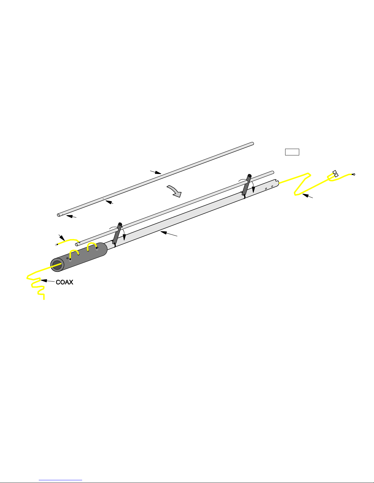
A) Top Section:
1) Place the Main Section on the clean, flat surface you've chosen for assembly. Stretch the coax out from
both ends. Locate the DX-VII1 assembly drawing and place it nearby.
2) Select the Top Section. It has four screw holes at one end. Place this end next to the coaxial cable which
is terminated in three connectors.
3) Refer to the assembly drawing. An assistant should lift the Main Section, while you slip the Top Section
over the coaxial cable. Tilting the Main Section downward slightly will permit gravity to slide the coax along
inside the Top Section.
4) Insert the Top Section into the Main Section. Gently push the Top Section into the Main Section beyond
the matching holes, until the 3 connectors and coax appear at the top end. Do not use excessive force
pulling coax out, but continue sliding the top section until the 3 leads appear.
5) Select the Top Cap unit. Connect it to the spade connectors on the coaxial cable. Make sure male spades
align properly and do not get pushed to one side.
6) VERY CAREFULLY slide the top section back over the coax and top cap assembly. Make sure you do
not disconnect the top cap unit as you slide the Top Section over it. The yellow lead should stick out of the
Top Section. We'll come back to that in a moment.
7) Slide the Top Section upward and rotate gently, until the holes align. Insert 4 screws and lock washers in
the holes, and tighten.
8) Now look in the top section, and be sure the Top Cap is below the screw hole in the aluminum tube. If not,
use the nut driver to push it downward slightly.
9) Place the yellow lead in the routed "slot" and then over the single dri ll hole. Attach with a screw and lock
washer making sure not to put screw through the Top Cap Unit.
10) Locate the dust cover (black). Push into the top of antenna. Do not cover the "open" notch area with
sealant.
B) Mid-Section:
1) Place the Mid-Section sub-assembly next to the Main Section. The end with yellow leads goes to the GAP
insulator.
2) Slide the long end of the coaxial cable through the Mid-Section assembly.
3) Carefully slide the Mid-Section into the GAP center insulator of the Main Section. Align the holes.
CAUTION: DO NOT PUSH THE MID-SECTION TUBE BEYOND THE SCREW HOLES, AS YOU CAN
DAMAGE THE INTERNAL GAP LEADS.
4) When the holes are properly aligned, the stand-offs should be parallel to the ground. The tuner
rods/stand-offs may be rotated about the Mid-Section if needed.
5) With the holes properly aligned, fasten the Mid-Section in place using 4 screws and lock washers.
Tighten.
3.3 C Lower Section
1) Find the Lower Section sub-assembly. Position it such that the end with the “notch" is away from the GAP
insulator.
2) Slide the remaining coax through the Lower Section Assembly. A few feet of cable should extend belo w
the tubing.
3) Now slide the Lower Assembly tube over the bottom of the Mid-Assembly tube. Align the 4 screw holes.
Insert 4 screws and lock washers. Tighten. 4) Refer to the assembly drawing. Twist the lower section
standoffs such that the tuner rods are also parallel to the ground. 5) Each of the tuner rods has a screw and
lock washer near its top, which you started previously. Connect each of the black jumper wires to the Lower
Tuner Rod nearest them, using these screws. Tighten.
3.3 D Base Section
1) A few feet of coaxial cable extends from the notched end of the Lower Section. Using a cable stripper or
sharp knife, remove 1.5" of the outer plastic covering, exposing the coax braid.
2) At the point where the braid meets the plastic outer jacket, bend the coax to form a 90 degree bend.
3) Find the double-walled Base Section. Position the Base Section with the small holes nearest the coa x,
and the large hole facing upward.
4) Grasp the coax with the 90 degree bend. Position it so the 90 degree bend points upward.
Page 6

5) insert the bent coax into the Base Section toward the large hole. The bend should continue to point
upward. When the coax reaches the large hole, the free end of the coax will pop through.
6) Gently pull the coax through the hole. Slide the Base Section into the Lower Section. Continue to pull
carefully on the cable. Stop when the cable is aligned with the notch in the Lower Section, and the four
screw holes line up.
7) insert 4 screws and lock washers, and tighten.
3.3 Electrical
1) The double yellow transition wire from the Mid-Tuners and the upper GAP lead attac h to the screw above
the GAP. This requires removal and re-tightening of the screw above the GAP.
GAP INTER CONNECTS
TOP TUNER ROD
TOP
UPPER GAP LEAD
DOUBLE TRANSITION
LOWER
GAP LEAD
MID-TUNERS
2) Connect the transition from the Top Tuner Rod and the lower GAP lead to the screw below the GAP.
3) The tuner rods should match the figure. If they do not, rotate the appropriate stand-offs until they agree.
4) Attach the PL-259 coaxial connector to the cable. Solder. If in doubt as to how to correctly perform this
task, refer to The Radio Amateurs Handbook. When complete, use an ohm-meter to determine that there is
no short between the center pin and shell of the PL-259.
3.3 IF Radials
1) Three 25' radials are required. These must be insulated, and may be made of wire as small as #14. Old
coaxial cable, RG8, RG58 or RG59 works quite well. If using coax, strip back 1.5" of outer insulation, and
solder a 4" wire to the shields of the three ends to make a connection. Attach the wire to one of the two
lower screws at the base of the antenna. Deploy the radials approximately 120 degrees apart.
CHAPTER 4: RAISING THE ANTENNA
4.1 Ground Mounted
A) Two people are needed for this operation. Carry the DX-VIII to the site. Place the bottom of the Base
Section on the ground, next to where the Mount Section comes out of the ground.
B) One person should *toe" the antenna; holding the bottom in place with his foot. The other person shoul d
lift the antenna at the middle, until he is holding it over his head.
C) The person holding the antenna should then walk toward the base of the antenna, pushing the DX-VIII
vertical as he goes.
Page 7

D) Once vertical, the "toe" person should grasp the antenna at the bottom. Both people shall lift the antenna
slightly. Guide the antenna over the base mount tube and insert. Twist slightly to aid in seating antenna i n
the tube.
E) Connect the three radials to one of the lower screws at the base of the antenna. Dress them in the
desired position.
F) Using a PL-258 barrel, connect a coaxial line to the Challenger DX-VIII antenna. Proceed to the section
on initial test.
4.2 Roof Mounted
A) The Challenger DX-VIII may be mounted on a roof. But both mounting and the electrical environment
contain many unknowns in this situation. Always test the antenna at ground level before installing it
permanently.
B) Mounting Guidelines: You must make provision for 4 non-conductive rope guys. TV antenna hardware
generally is not robust enough to support the vertical without them. The same is true of chimney mounts.
Guys should be fastened above the GAP insulator, using a stainless steel hose clamp.
C) The counterpoise should not be above the ham shack, or sensitive consumer electronics within the
home. If possible, run the counterpoise along the edge of the roof.
D) If the DX-VIII is mounted at the edge of the roof, the support pipe should be insulated from the antenna
with PVC tubing.
E) Test the antenna at ground level before installing it in the air:
1) Find a spot in the yard with enough room to erect the antenna temporarily. Trees or cinder blocks are
useful temporary guy anchors.
2) Affix guys to the antenna.
3) Dig a shallow X diameter hole to hold the bottom of the antenna in place.
4) Use an assistant to help place the bottom of the antenna in the hole, and pull the antenna vertical. One
person should hold the antenna vertical while the other ties the guys in place temporarily.
5) Follow the instructions in section 5.0 Initial Test.
6) Once satisfied that the antenna works properly, you may mount it in the desired locati on.
CHAPTER 5: INITIAL TEST
5.0 General
A ham band transceiver and SWR meter are required for these tests. It is recommended that you use the
minimum necessary power for the measurement. If possible, use an SWR bridge separate from that
provided in your transceiver.
Using a pencil, record your data in the space provided on below.
5.1 First Operation
A) If the GAP Antenna has been assembled properly, it will resonate close to the center frequency selected
for 75 -80 meters. You should also see a useable bandwidth of about 130 KHz between the 2.0: 1 VSWR
points. Record the following data, using a pencil:
VSWR center freq:__________ VSWR at center 1.___:1
2.0: 1 lower freq: ___________ 2.0: 1 upper freq: _________
B) Next, move to 40 meters. Using the minimum power possible, record the following data. The GAP vertical
is especially low 0. and should be below 2.0: 1 across the entire band.
Freq: 7.0 VSWR:
7.1
7.2
7.3
C) 20 meters is next.
Freq: 14.0 VSWR:
14.1
14.2
14.3
D) 15 Meters.
Freq: 21.0 VSWR:
21.1
21.2
21.3
21.4
Page 8

E) 12 meters.
Freq: 24.9 VSWR:
24.95
24.99
F) 10 meters.
Freq: 28.0 VSWR:
28.5
29.0
29.5
H) The antenna should provide 2.0: 1 VSWR or less over the bands indicated, so long as nothi ng in the
immediate environment is coupled to it.
CHAPTER 6:
Tips and Troubleshooting should help you diagnose the situation, if your performance is other than
expected.
CHAPTER 6: TIPS AND TROUBLESHOOTING
6.1 General
The Challenger DX antenna has been designed to operate on the eight bands specified. Operation outside
the specified bands may damage the antenna.
Use of an antenna tuner is not required and not recommended. Tuners will not improve the performance of
the antenna, although they may permit a solid state transmitter to put out more power.
Operation of the antenna using a tuner on any frequency where the VSW R exceeds 2:1 may damage the
antenna. Use when VSWR is less than 2:1 is acceptable.
6.2 Malfunction
A) If the antenna fails to resonate on the 75/80 meter band the CAP unit plugged on at the top of the
antenna may not be making proper contact or was inadvertently shorted when the screw was inserted. If the
top CAP is not fully connected , the antenna will resonate at 5.9MHz. If the CAP is shorted, the antenna will
resonate at 3.06 MHz. Check to see if the top CAP unit is connected. If it is , contact the factory for
assistance.
B) If all your standing waves are high, double check the PL259 connector at the base of the antenna and
make sure it is open from center pin to shield.
C) If only a couple of bands are high eliminate the following possibilities;
1) Bad coaxial feed line. If the coax has been in use for some time, it may be contaminated. Place a 50 ohm
dummy load at the far end of your feed line, in place of the antenna. Any indication of varying VSW R or a
standing wave greater than 1:1 suggest defective coax.
2) Mutual coupling with nearby vertical metal objects may detune the CHALLENGER. Check to see if any of
the items suggested in section 1.2 & 1.3 apply.
3) Transceivers with built in SWR bridges may not correctly indicate when their power reduction circuits take
over. Retest with a separate VSWR meter.
4) The transceiver or transmitter may be emitting a spurious signal in addition to the desired signal. R etest
using the lowest possible power level. If possible try another rig.
If you are unable to solve the problem, contact the factory for assistance. Please have section 5.1 filled in
and handy when you call. We do not charge for assistance and our phone number is (561) 571-9922.
WARRANTY
GAP Antenna Products, Inc. Provides a a limited warranty on it's products against any defects in material
and
workmanship for a period of 90 days after date of purchase/shipment. This warranty applies to the origin al
purchaser only. Purchaser should return defective product freight prepaid. GAP reserves the right to repair
or replace product, at it's discretion. Repaired or replaced product will be shipped freight prepaid within 30
days of customer return. This warranty is provided in lieu of any other warranty expressed or implied. The
warranty is void if the product is subject to misuse, improper installation, accident, neglect, modification,
repairs or act of God.
GAP Antenna Products, Inc. Shall assume no liability for incidental or consequential damages resulting from
the purchaser's ownership of it's products.
REPLACEMENT PARTS
Replacement parts are available for any portion of the antenna. Contact factor y for details.
DESIGN BASELINE
GAP Antenna Products, Inc. Reserves the right to incorporate improvements and changes in the design
without obligation to update previously manufactured units.
 Loading...