

CellarPro 4200VSX User Manual
Control the Elements
Owner’s Manual –
3200VSi / 3200VSx / 4200VSi / 4200VSx
C O N G R A T U L A T I O N S !
Thank you for purchasing a new CellarPro cooling system.
Please take a minute to read through this Owner’s Manual before you unpack,
install and turn on your Cooling Unit.
If you have any questions about your new cooling unit, it is likely that you will find the
answers in this Owner’s Manual. We also have more information on our website,
including the latest version of the Owner’s Manual, at
www.cellarpro.com/customerservice .
If you still have questions, please don’t hesitate to contact your dealer or CellarPro
directly. We can be reached during normal business hours at 1.877.726.8496. You also
may contact us anytime via email at info@cellarpro.com.
Contact Information:
CellarPro Cooling Systems
531 Mercantile Drive
Cotati, CA 94931
877.726.8496
Email: info@cellarprocoolingsystems.com
Website: www.cellarprocoolingsystems.com
Serial Number*________________________
*We recommend that you take a minute to fill-in your CellarPro serial number above.
The serial number has seven-digits and can be found on the printed label on the left
side of your cooling unit.
Don’t forget to register your cooling unit warranty at www.cellarpro.com/register
Table of Contents
I. Specifications 4
II. Installation Instructions 10
III. Operating Instructions 19
IV. Troubleshooting 30
V. Limited Warranty 32
3

I. Specifications
Specs and Cut Sheets
Model Dimensions (inches)
3200/4200VSi
3200/4200VSi*
3200/4200VSx
* With optional duct hood
W x D x H
14.1 x 25.1 x 19.6
(incl.drain)
14.5 x 29.3 x 19.7
(incl. duct hood & drain)
14.5 x 27.6 x 19.7
(incl. exterior case & drain)
3200VSi / 4200VSi Cut Sheet
Weight
Running Compressor
Amps
115
9.2 – 3200
123
11.5 – 4200
123
4
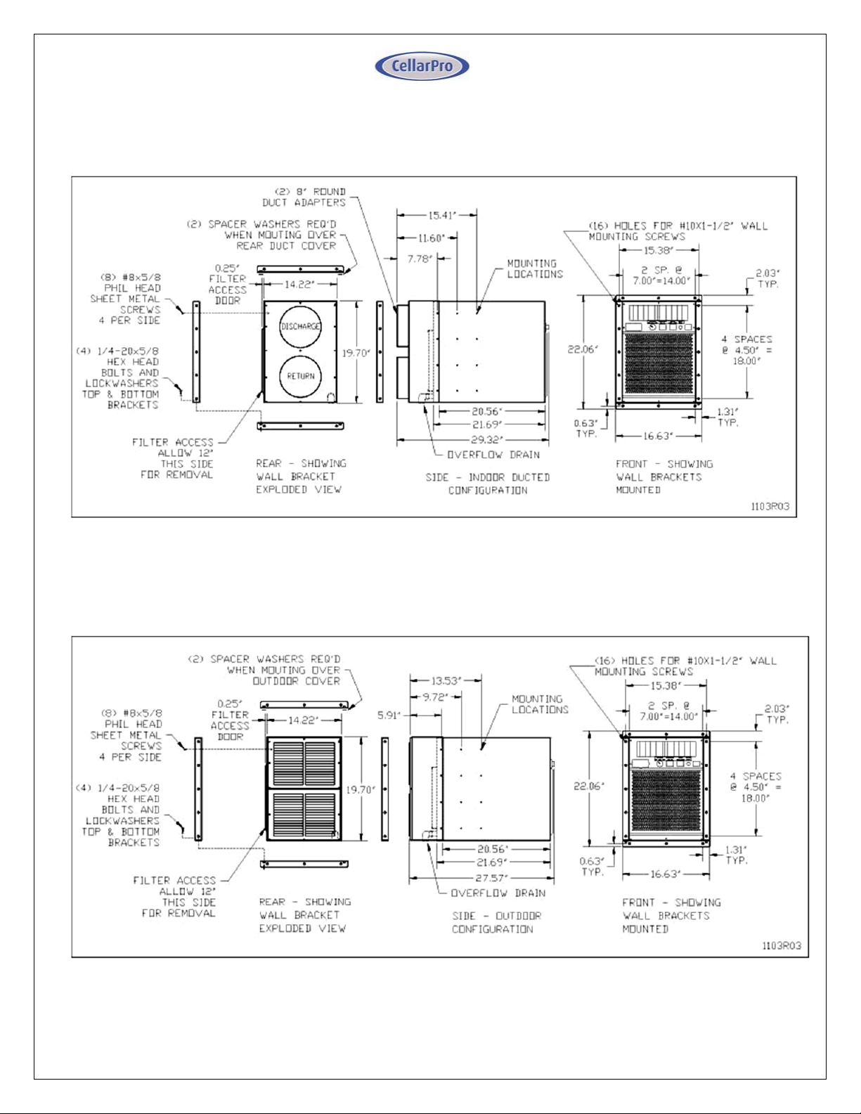
3200VSi / 4200VSi (with Rear Duct Hood) - Cut Sheet
3200VSx / 4200VSx Cut Sheet
5

Placement
CellarPro 3200 and 4200 Series cooling units are designed to be installed THROUGH THE
WALL, so that the rear and the front of the cooling unit DO NOT SHARE THE SAME AIR
SPACE.
The rear of the cooling unit must be installed in a space that is at least as large as the wine
cellar unless the rear intake and exhaust are ducted. Both the front and the rear of the
cooling unit require a minimum clearance of 8 inches.
These units also can be placed completely INSIDE or OUTSIDE the cellar when used in
combination with our duct kits.
Ambient Environment
3200VSi / 4200VSi - designed for internal use only (ie sheltered from outdoor
weather), the rear of the unit can be exposed to temperature conditions ranging
from 40 to 115°F.
3200VSx / 4200VSx – designed for external use, the rear of the unit can be
exposed to temperature conditions ranging from 40 to 115°F. Refer to the
Installation section for additional requirements for outdoor exposures.
PLEASE NOTE: With our (optional) crankcase heater, all of our cooling units can
be used in environments down to 20°F, and with our (optional) low ambient kit, all of
our cooling units can be used in environments down to -20°F.
CellarPro cooling units are not designed to heat the cellar space, so if
temperatures inside the cellar drop below proper wine storage temperatures, the
cooling unit cannot create heat inside the cellar.
Insulation
CellarPro cooling units are
designed to be installed
inside wine cellars that have
proper insulation, moisture
barriers and an airtight seal
from the environment
outside the cellar. Interior
walls and floor should
have a minimum of R-11
insulation, and a vapor barrier
on the warm side of the
insulation. The ceiling should
6

have a minimum of R-19 insulation and a vapor barrier on the warm side of the
insulation. Doors also should be insulated and tightly sealed with weather
stripping around the perimeter of the door. Surface-mounted
fixtures are recommended over recessed lighting, which can allow air to leak
into the cellar.
It is important that all walls, joints, doors and windows, electrical outlets
and/or switches, pipes, vents and light fixtures be sealed to prevent air and
moisture from entering the cellar. If there is a leak in the cellar, the cooling unit will
build up excess condensation.
CellarPro 3200 and 4200 cooling units are equipped with a condensate
management system, which includes a stainless steel pan, a thermostaticallycontrolled electric heating element, and an overflow drain at the rear of the
cooling unit.
We strongly recommend that the overflow drain line (shipped loose with the
cooling unit) be connected to the overflow drain (as shown in the installation
section), and that the cooling unit be mounted to tilt slightly backwards, so that
any overflow condensate is channeled safely to the overflow drain line. In addition,
we recommend turning on the electric heating element to burn off excess
condensate that accumulates in the stainless steel pan during the initial cooling of
the cellar and during high run-times, as well as in high-humidity environments.
Fan Speeds
Your fan speed setting will need to be on “High” under the following conditions:
- As the thermal load of the wine cellar increases
- As ambient temperatures increase
- As the static load from ducting (if any) increases due to factors including the
length of the duct run, turns, vent grills and/or reducers
Ventilation
Adequate ventilation is critically important for the proper operation of your
CellarPro cooling unit.
OUTSIDE THE CELLAR
(At the rear of the cooling unit)
Condenser Air Exhaust. CellarPro 3200 and 4200 Series cooling units create
significant hot air which must be exhausted into an appropriately-sized space
in order for the heat to dissipate. If the space is constrained and/or too small,
7
the heat will not dissipate. In this event, the cooling unit will be forced to recirculate its hot air exhaust and/or the static pressure will back up the cooling
unit. If this happens, the cooling unit’s ability to create cold air inside the cellar
will be compromised.
Condenser Air Intake. The condenser coils require access to cool air in order
for the cooling unit to produce cold air. In addition, the cooling unit must be
installed so that, after its installation, the condenser coils are accessible for
periodic cleaning or replacing of the filter.
The rear of the cooling unit must be installed in a space that is at least as large as the
wine cellar unless the rear intake and exhaust are ducted. Both the front and the rear
of the cooling unit require a minimum clearance of 8 inches.
Ducting. CellarPro 3200 and 4200 units allow the condenser air intake and
exhaust each to be ducted up to 50 equivalent feet with 8” diameter ducting, or
100 equivalent feet with our auxiliary fan and 8” diameter ducting. We offer two
rear duct kits (sold separately) that attach to the rear of the cooling unit.
INSIDE THE CELLAR
(At the front of the cooling unit)
Evaporator Air Intake. CellarPro cooling units should be mounted at the
highest point inside wine cellars, so that warm air – which rises – will be the first to
pass over the evaporator coils, which are located behind the grill on the face of
the cooling unit. When the warm air passes across the evaporator coils, heat is
removed the air, and the resulting cold air is exhausted into the cellar. To ensure
proper airflow, minimum clearance of 12” is required in front of the cooling unit.
Evaporator Air Exhaust. Cold air is exhausted at the top front of the cooling
unit. Because CellarPro cooling units are located at the highest point inside
wine cellars, the cold air exhaust eventually will drop to the bottom of the cellar.
To ensure proper airflow and reduce temperature stratification inside the cellar,
the space in front of the cold air discharge should be clear of any obstructions,
including wine bottles, wine racks, etc.
Ducting. CellarPro 3200 and 4200 units allow the evaporator air intake and
exhaust each to be ducted up to 50 equivalent feet with 8” diameter ducting.
We offer a front duct kit (sold separately) that attaches to the front of the
cooling unit.
We also offer a remote control panel kit that can be installed remotely (up to 10
feet) from the cooling unit, either inside or outside the cellar, and a bottle probe
(10 foot cord) that can be plugged into the cooling unit.
8

Power Requirements
CellarPro cooling systems should be plugged into a dedicated non-GFI outlet
connected to a 15-amp circuit. The cooling unit uses approximately 11.5 (4200)
and 9.2 (3200) amps during its “on” cycle.
A number of variables, including the minimum set point, the temperature in the
ambient environment, the insulation of the cellar, and the thermal mass inside
the cellar, will affect the cooling unit’s runtime. It is normal for the cooling unit
to run up to 75 percent of the time in order to maintain proper conditions inside
the cellar.
Select a power receptacle (Front or Rear) and plug the provided power cord into
that receptacle. Plug the other end of the power cord into a dedicated 15 amp
circuit. A surge-protected circuit is recommended. Set the power selector
switch to energize the appropriate receptacle used (Front or Rear).
The power cord provided for the model 3200VSi and 4200VSi is approved for
indoor use only, while the power cord for model 3200VSx and 4200VSx may be
used both for indoor or outdoor applications.
9
II. Installation Instructions
TEST THE UNIT BEFORE INSTALLING IT
1. Remove the unit from the box. SAVE THE BOX AND PACKING
MATERIALS.
2. Plug in the power cord and let the unit run on a hard, flat surface for no
more than 5 minutes.
3. Check to make sure that both fans (one in the front and one at the rear of
the cooling unit) are blowing.
4. Check that the cooling unit is discharging cold air from the front (it should
be approximately 10 - 12° F colder than the temperature on the digital
display)
5. Please note: The cooling system is programmed with a 3-Minute Delay
at Startup to protect its internal components
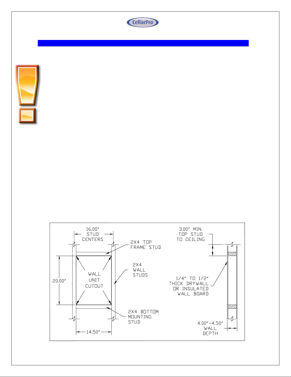
Cut a hole in the wall that is 1/4 inch larger than the dimensions (W x
H) of the cooling unit, and create a frame to support the rear of the
cooling unit. The rear of the cooling unit should be supported by the wall
through which it is installed. Horizontal 2 x 4 inch braces should be installed
between the studs below and above the cooling unit. If the studs in the wall
must be cut to accommodate the width of the cooling unit, vertical braces also
should be installed on either side of the cooling unit.
3200 / 4200 Frame and Cut-Out Diagram
10
 Loading...