

Page 1
Control the Elements
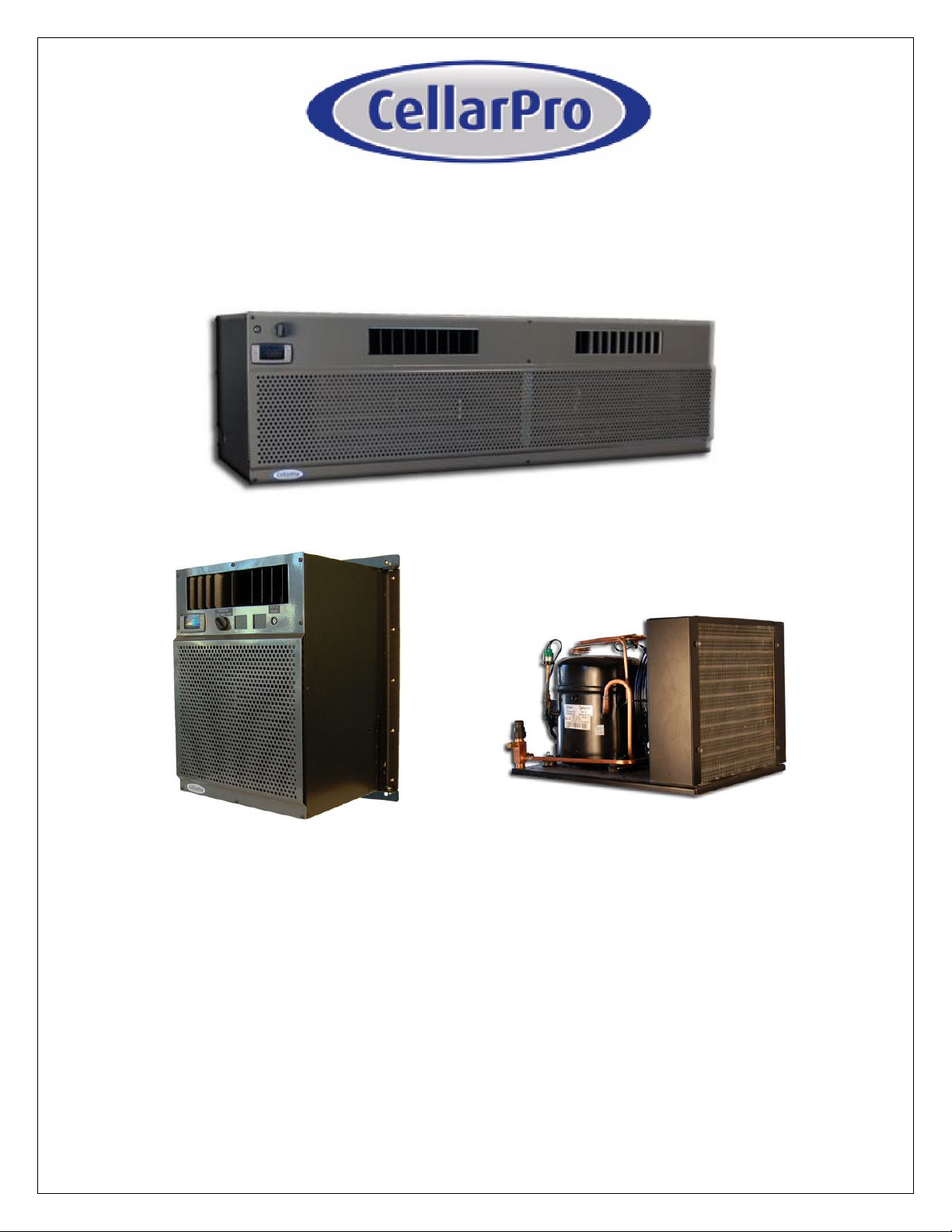
Split Refrigeration Systems
Owner’s Manual
V10.14
Page 2
C O N G R A T U L A T I O N S !
Thank you for purchasing a new CellarPro cooling system.
Please take a minute to read through this Owner’s Manual before you unpack,
install and turn on your Cooling Unit.
If you have any questions about your new cooling unit, it is likely that you will find the
answers in this Owner’s Manual. We also have more information on our website,
including the latest version of the Owner’s Manual, at www.cellarpro.com/customer-
service .
If you still have questions, please don’t hesitate to contact your dealer or CellarPro
directly. We can be reached during normal business hours at 707.794.8000. You also
may contact us anytime via email at [email protected].
Contact Information:
CellarPro Cooling Systems
1445 N. McDowell Blvd
Petaluma, CA 94954
707.794.8000
Email: [email protected]
Website: www.cellarprocoolingsystems.com
IMPORTANT WARRANTY INFORMATION FOR YOUR SPLIT SYSTEM
Make sure to activate your warranty by having the installing technician complete
the Support and Data Service Sheet at the end of this Owner’s Manual. Once
completed, please fax to us at 707.794.8005, or scan and email to us at
Once we receive the completed Sheet, we'll review the data to make sure the cooling
system is installed properly.
YOUR WARRANTY WILL NOT BE ACTIVATED UNTIL WE RECEIVE THE
COMPLETED CHECKLIST AND INSTALLATION ISSUES (IF ANY) HAVE BEEN
RESOLVED. If the unit malfunctions, we cannot assist you unless/until we receive the
completed checklist. If the unit is damaged because of improper installation, repair
services will be provided on a time and materials basis.
V10.14
Page 3
Table of Contents
I. Package Contents 4
II. Specifications, Cut Sheets, and Cellar Construction 5
III. Installation Instructions 10
IV. Operating Instructions 32
V. Troubleshooting 39
VI. Limited Warranty 44
VII. Warranty Activation Checklist 45
3 V10.14
Page 4
3000S, 4000S
BOX 1:
DESCRIPTION
QTY
EVAPORATOR
1
TOP MOUNTING BRACKET
2
SIDE MOUNTING BRACKET
2
WALL MOUNTING SCREWS
16
DRAIN TUBING
10 FT.
OWNERS MANUAL
1
CORK TAPE
1 FT.
DRAIN KNOCKOUT SNAP BUSHING
1
SIGHT GLASS
1
FILTER DRIER
1
BOX 2:
DESCRIPTION
QTY
CONDENSING UNIT
1
BOX 3 (OPTIONAL):
DESCRIPTION
QTY
CONDENSING UNIT OUTDOOR COVER
1 SET
COVER ASSEMBLY HARDWARE
1 SET
3000Sh, 4000Sh, 6000S, 8000S
BOX 1:
DESCRIPTION
QTY
EVAPORATOR
1
REAR WALL MOUNTING BRACKET
2
WALL MOUNTING SCREWS
6
DRAIN TUBING
10 FT.
OWNERS MANUAL
1
CORK TAPE
2 FT.
DRAIN KNOCKOUT SNAP BUSHING
1
HOLE PLUGS FOR ANCHOR BOLTS
2
SIGHT GLASS
1
FILTER DRIER
1
BOX 2:
DESCRIPTION
QTY
CONDENSING UNIT
1
BOX 3 (OPTIONAL):
DESCRIPTION
QTY
CONDENSING UNIT OUTDOOR COVER
1 SET
I. Package Contents
4 V10.14
Page 5
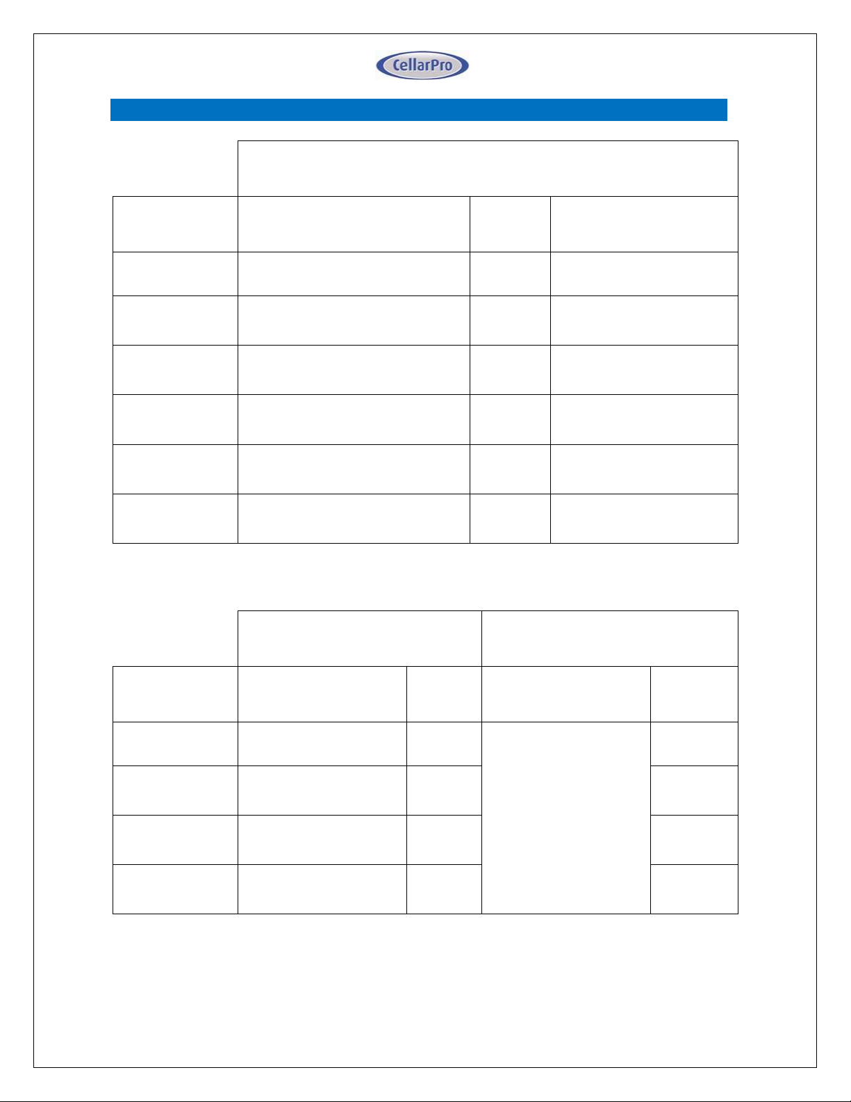
Evaporator
Model
Dimensions
W x D x H (inches)
Weight
(lbs.)
Running Amps
(with fan on “high”)
3000S
16.6 x 12.6 x 22.1
(incl. mounting brackets)
40
6.2
3000Sh
30.4 x 14.4 x 13.2
(incl. mounting bracket)
63
6.2
4000S
16.6 x 12.6 x 22.1
(incl. mounting brackets)
42
8.9
4000Sh
30.4 x 14.4 x 13.2
(incl. mounting bracket)
65
8.9
6000S
30.4 x 14.4 x 13.2
(incl. mounting bracket)
68
13.1
8000S
46.4 x 14.4 x 13.2
(incl. mounting bracket)
85
15.4
Condensing unit - Indoor
Condensing unit - Outdoor
Model
Dimensions
W x D x H (inches)
Weight
(lbs.)
Dimensions
W x D x H (inches)
Weight
(lbs.)
3000S,
3000Sh
13.5 x 18.9 x 9.1
42
19.4 x 23.3 x 18.8
(with cover)
73
4000S,
4000Sh
13.5 x 18.9 x 10.3
45
76
6000S
13.9 x 18.9 x 11.9
54
85
8000S
16.8 x 20.8 x 14
76
107
II. Specifications, Cut Sheets and Cellar Construction
5 V10.14
Page 6
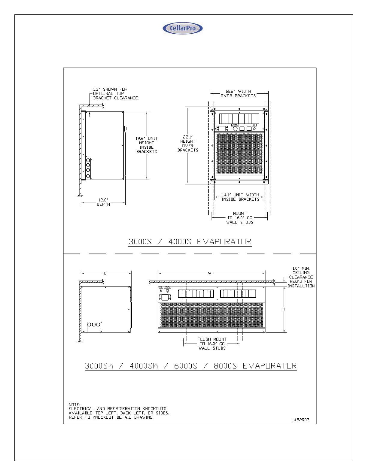
Evaporator Cut Sheets
6 V10.14
Page 7
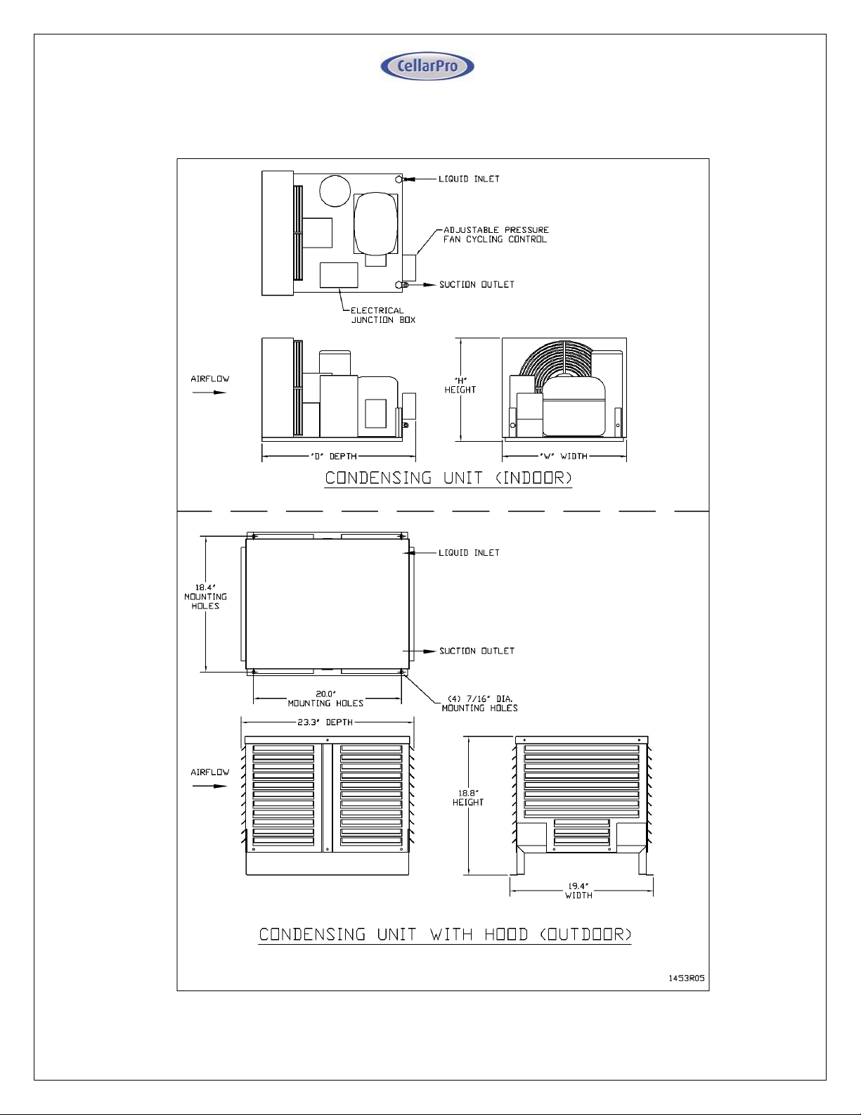
Condensing Unit Cut Sheets
7 V10.14
Page 8
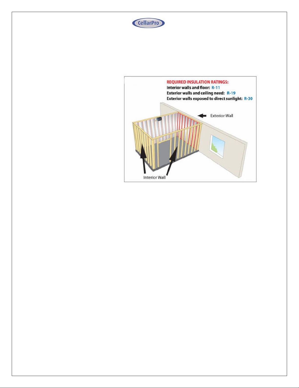
Insulation
CellarPro cooling units are designed to be installed inside wine cellars that have
proper insulation, moisture barriers and an airtight seal from the environment
outside the cellar. Interior walls and floor should have a minimum of R-11
insulation, and a vapor barrier
on the warm side of the
insulation. The ceiling should
have a minimum of R-19
insulation and a vapor barrier
on the warm side of the
insulation. Doors also should
be insulated and tightly
sealed with weather
stripping around the
perimeter of the door.
Surface-mounted fixtures
are recommended over
recessed lighting, which can
allow air to leak into the
cellar.
It is important that all walls,
joints, doors and windows, electrical outlets and/or switches, pipes, vents and
light fixtures be sealed to prevent air and moisture from entering the cellar. If there is
a leak in the cellar, the cooling unit will build up excess condensation.
The drain line (shipped loose with the cooling unit) must be connected to the drain
pan (as shown in the installation section).
Fan Speeds
Your fan speed setting will depend on the thermal load on the wine cellar, and the
resulting BTU that is required to cool and maintain your wine cellar at the desired
temperature.
Ventilation
Adequate ventilation is critically important for the proper operation of your CellarPro
cooling unit.
8 V10.14
Page 9
Outside the Cellar
Condensing unit Air Exhaust. Condensing units create significant hot air which
must be exhausted into an appropriately-sized space in order for the heat to
dissipate. If the space is constrained and/or too small, the heat will not dissipate.
In this event, the cooling unit will be forced to re-circulate its hot air exhaust and/or
the static pressure will back up the cooling unit. If this happens, the cooling unit’s
ability to create cold air inside the cellar will be compromised.
Condenser Air Intake. The condenser coils require access to cool air in order for
the cooling unit to produce cold air. In addition, the cooling unit must be installed
so that, after its installation, the condenser coils are accessible for periodic cleaning.
The Condensing unit cannot be ducted.
Inside the Cellar
Evaporator Air Intake. When the warm air passes across the evaporator coils, heat
is removed from the air, and the resulting cold air is exhausted into the cellar. To
ensure proper airflow, minimum clearance of 12” is required in front of the cooling
unit.
Evaporator Air Exhaust. Cold air is exhausted at the top front of the cooling unit.
Because CellarPro cooling units are located at the highest point inside wine cellars,
the cold air exhaust eventually will drop to the bottom of the cellar. To ensure proper
airflow and reduce temperature stratification inside the cellar, the space in front of
the cold air discharge should be clear of any obstructions, including wine bottles, wine
racks, etc.
Ducting For the Evaporator (3000S/4000S Models). Cold air exhaust and return
(from the evaporator) can be ducted with our front duct hood up to 100 equivalent
feet of total ductwork, or 50 equivalent feet for both the discharge and return
ducting, using 8” diameter insulated ducting. Our front duct kit is compatible
exclusively with our 3000S and 4000S cooling units. If you’d like to duct one of our
larger cooling units, please consider our AH6500 and AH8500 cooling units.
Before attaching the front duct hoods, remove the front grill (if present) from the
front of cooling unit.
We also offer a remote control panel kit that can be installed remotely (up to 10 feet)
from the cooling unit, either inside or outside the cellar, and a bottle probe (10 foot
cord) that can be plugged into the cooling unit.
9 V10.14
Page 10
III. Installation Instructions
Installation Instructions
Split System piping and wiring must be installed by a qualified Refrigeration
Technician in accordance with local and national code requirements.
Condensing Unit Installation
Indoor and Outdoor Units
The unit is designed to operate in temperatures ranging from 0°F to 110°F. A
compressor heater (sold separately) is required for temperatures below 40°F.
Indoor Units
Condensing units can be installed remotely from the cellar in an area protected
from direct exposure to moisture and sunlight.
The area must have suitable ventilation to maintain an ambient temperature of
110°F or less.
If the area does not have adequate ventilation, a vent fan should be added to
supply fresh air to the space (suggested 600CFM).
A minimum of 12" of open air space is required in front of the condenser coils.
Indoor units can be installed with the optional outdoor hood if additional
mechanical protection is desired.
A minimum of 12" of open air space around the perimeter of the outdoor hood
is required.
Outdoor Units
Condensing units must be installed with the outdoor hood if the unit will be
located outdoors.
A minimum of 12" of open air space around the perimeter of the outdoor hood
is required.
Evaporator Unit Installation
As warm air rises to the top of the cellar, the cooling unit pulls the warm air through
the evaporator coil and removes the heat from the warm air. Once cooled, the cold
air is discharged from the front of the cooling unit and circulates through the cellar.
Therefore, we recommend mounting the evaporator as close to the ceiling as
possible inside the cellar.
10 V10.14
Page 11
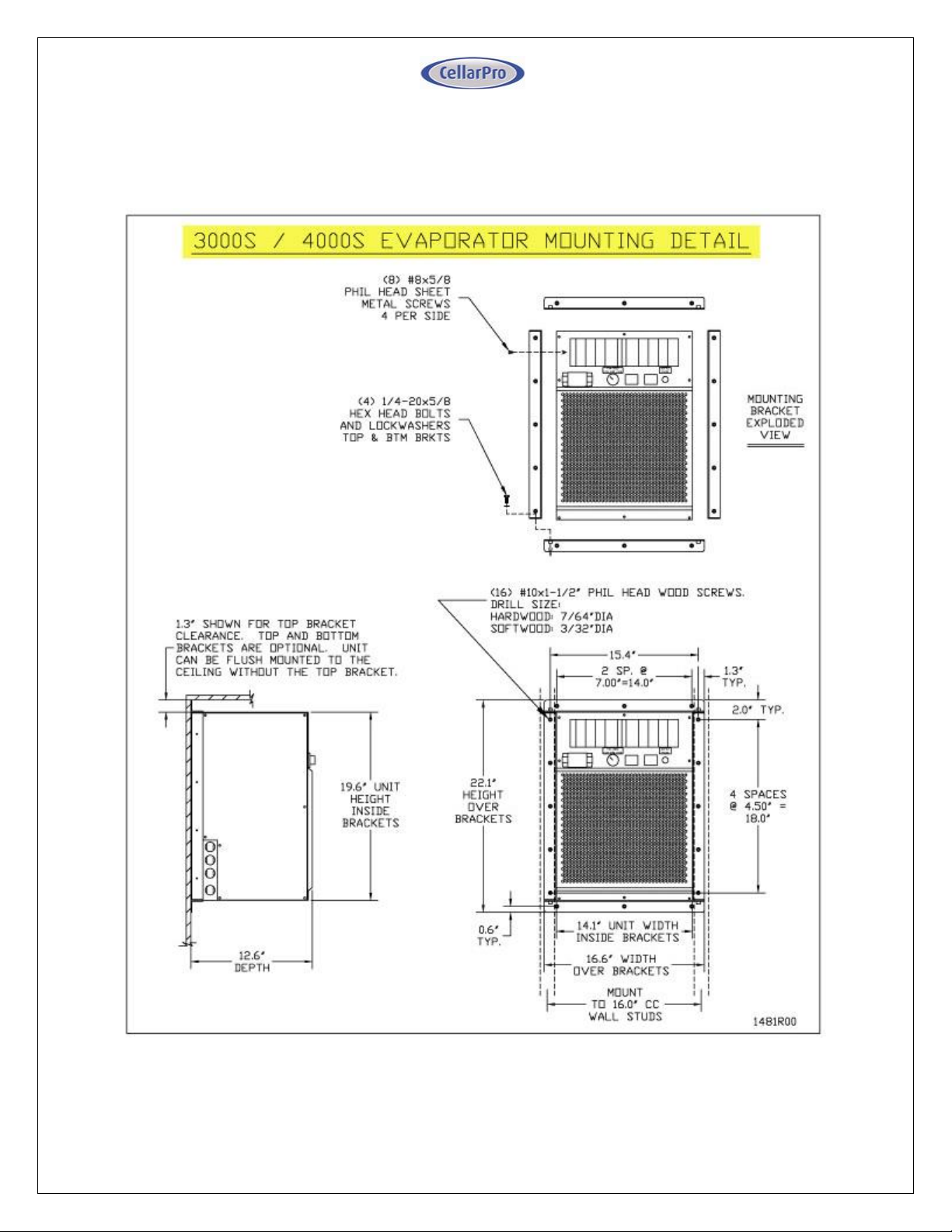
3000S / 4000S
Side mounting brackets are provided for mounting the evaporator flush to a wall
inside the cellar. Optional top and bottom brackets (non-load bearing) are available
upon request.
11 V10.14
Page 12
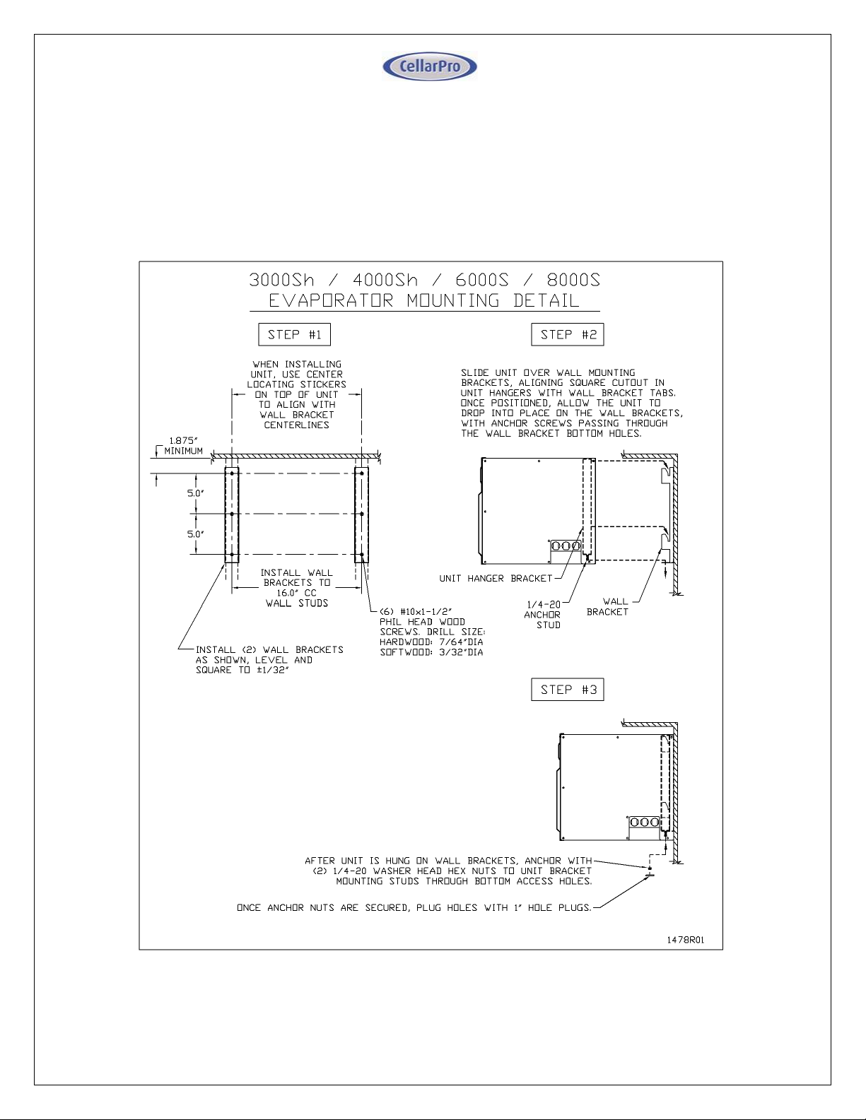
3000Sh / 4000Sh / 6000S / 8000S
Wall hangers are used to mount these split systems. First, wall brackets are
attached to the wall, and then the evaporator slides onto the brackets. After the
evaporator is installed, two bottom nuts must be installed on the recessed anchor
studs.
12 V10.14
Page 13
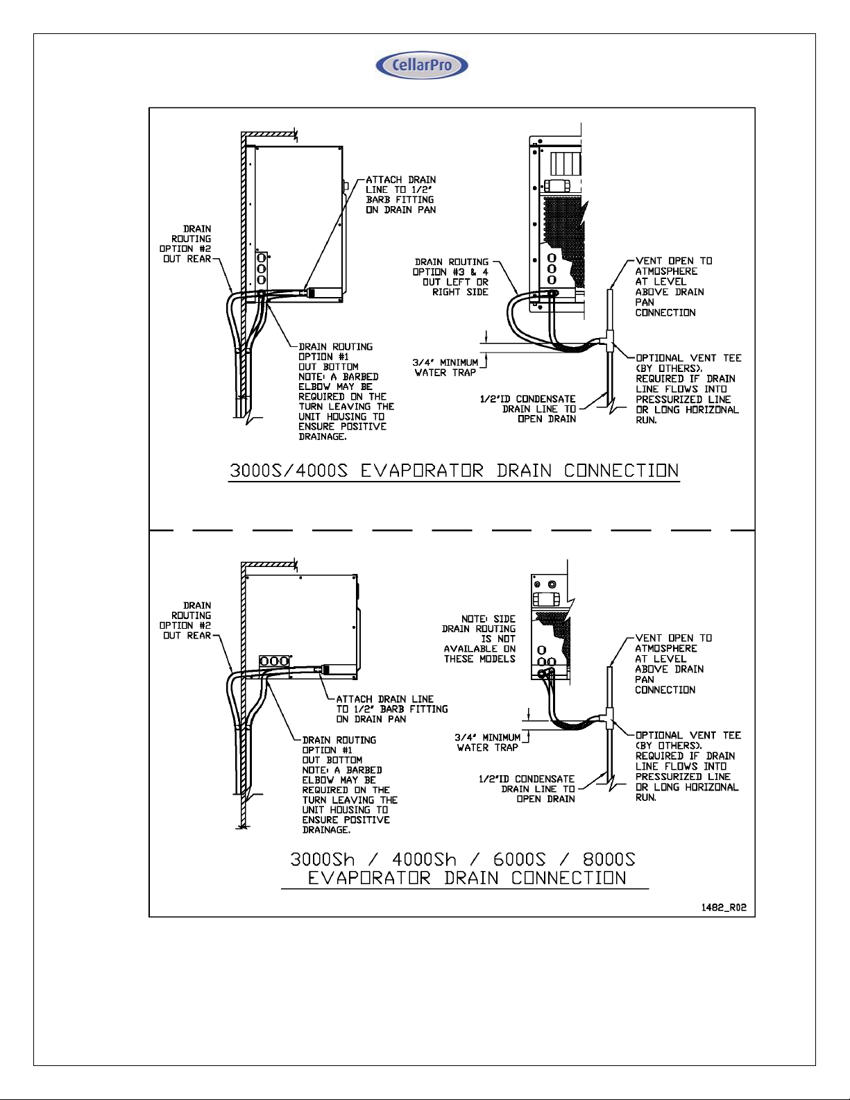
Condensate Drain Line
The condensate drain line should drop, then rise (but stay below the height of the
fitting), and then drop again into an open drain. Then, fill the trap with water. The
condensate trap will allow any excess moisture inside the Evaporator to
overcome the static pressure and flow out of the drain line. Before putting the unit
into service, test for positive drainage by pouring water into the drain pan and
observing flow through to the final drain.
13 V10.14
Page 14
14 V10.14
Page 15
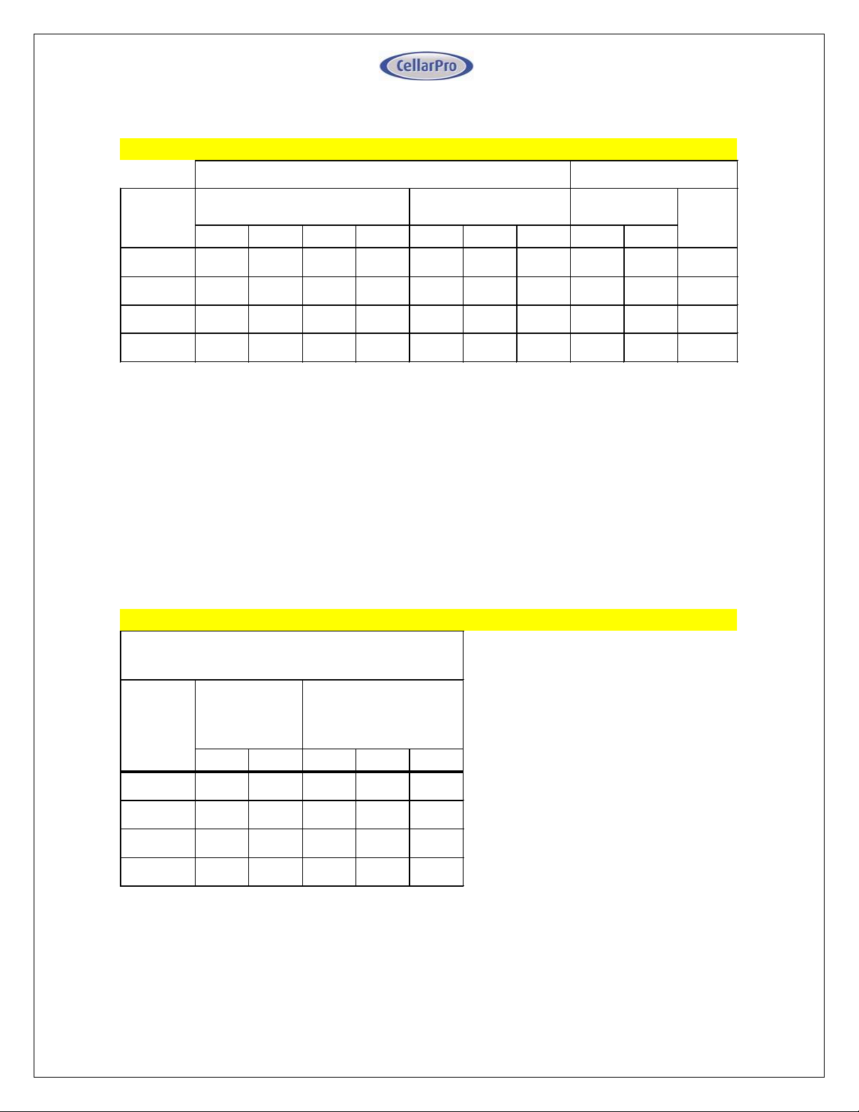
EVAPORATOR
CONDENSING UNIT
SPLIT
SYSTEM
FAN AMPS @ 115V/60HZ
POWER INPUT WATTS
UNIT AMPS @
115V/60HZ
POWER
INPUT
MODEL
MCA
HIGH
MED
LOW
HIGH
MED
LOW
MCA
LRA
WATTS
3000S/Sh
1.3
1.0
0.8
0.7
107
84
70
6.4
28.2
442
4000S/Sh
1.7
1.4
1.1
1.0
159
122
107
9.2
40.0
591
6000S
2.6
2.1
1.7
1.4
214
168
140
13.5
53.0
922
8000S
3.5
2.8
2.2
1.9
318
244
214
15.4
51.0
1028
NOTES:
SPLIT
SYSTEM
SYSTEM AMPS
POWER INPUT WATTS
MODEL
MCA
LRA
HIGH
MED
LOW
3000S/Sh
7.4
28.0
549
526
512
4000S/Sh
10.6
40.0
750
713
698
6000S
15.6
53.0
1136
1090
1062
8000S
18.2
51.0
1346
1272
1242
NOTES:
Option A: Dual Power / Valve Control
Option B: Single Power / Electronic Control
1) A 15 amp dedicated circuit breaker (non GFI) is recommended for 3000S/Sh and 4000S/Sh systems.
2) A 25 amp dedicated circuit breaker (non GFI) is recommended for 6000S and 8000S systems.
1) Separate 115V / 60HZ power supplies are required for the Evaporator and the Condensing Unit.
2) A 15 amp circuit breaker is recommended for all Evaporator models.
3) A 15 amp dedicated circuit breaker (non GFI) is recommended for 3000S/Sh and 4000S/Sh Con-
densing Units
5) A 25 amp dedicated circuit breaker (non GFI) is recommended for the 8000S Condensing Unit.
4) A 20 amp dedicated circuit breaker (non GFI) is recommended for the 6000S Condensing Unit.
SINGLE 115V 60HZ POWER SUPPLY TO/FROM
EVAPORATOR
Power Supply Requirements
15 V10.14
Page 16
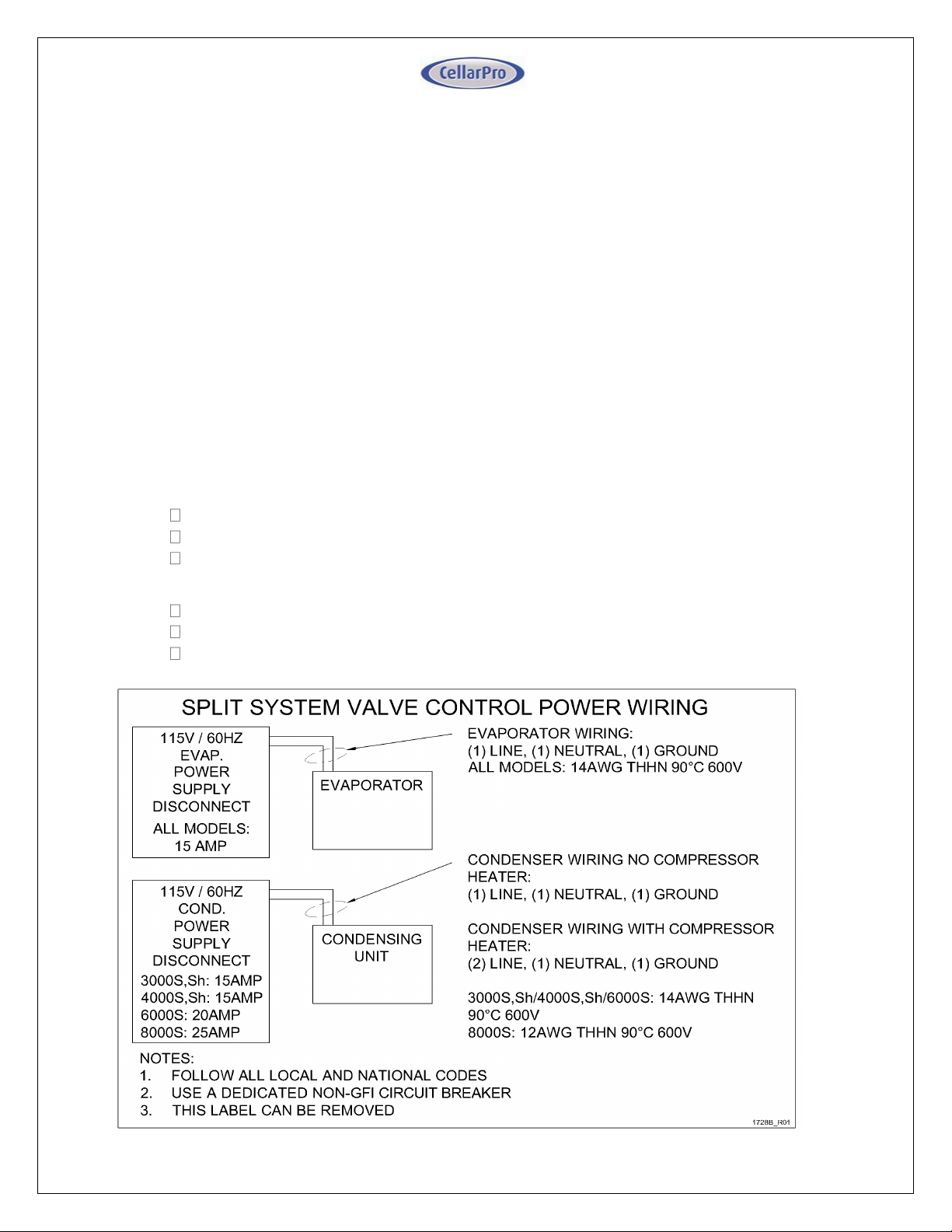
System Wiring – Option A: Dual Power / Valve Control
Under this configuration the Evaporator and Condensing units are separately
powered, and the Condensing unit turns on and off based on suction pressure, as
follows:
The Evaporator includes a factory installed liquid line solenoid valve (LLSV),
which is controlled by the Evaporator temperature controller. The Condensing
unit is controlled by a low pressure switch which reacts to the suction pressure
and senses whether the LLSV is open or closed.
When the Evaporator temperature set-point is reached and the Evaporator
turns off, the LLSV closes, causing the system to pump down until the low
pressure switch shuts off the Condensing unit.
When the Evaporator turns on, the LLSV opens, causing the suction
pressure to rise and activate the Condensing unit.
Field power wiring is connected to both the Evaporator and Condensing units, no
interconnecting wiring is needed between the Evaporator and Condensing unit.
Evaporator Field Power Wiring:
Connect line lead to Evaporator terminal "L"
Connect neutral lead to Evaporator terminal "N"
Connect power ground to grounding lug on Evaporator
Condensing Unit Field Power Wiring:
Connect line lead to Condensing unit terminal "L1"
Connect neutral lead to Condensing unit terminal "L2"
Connect power ground to grounding lug on Condensing unit.
16 V10.14
Page 17
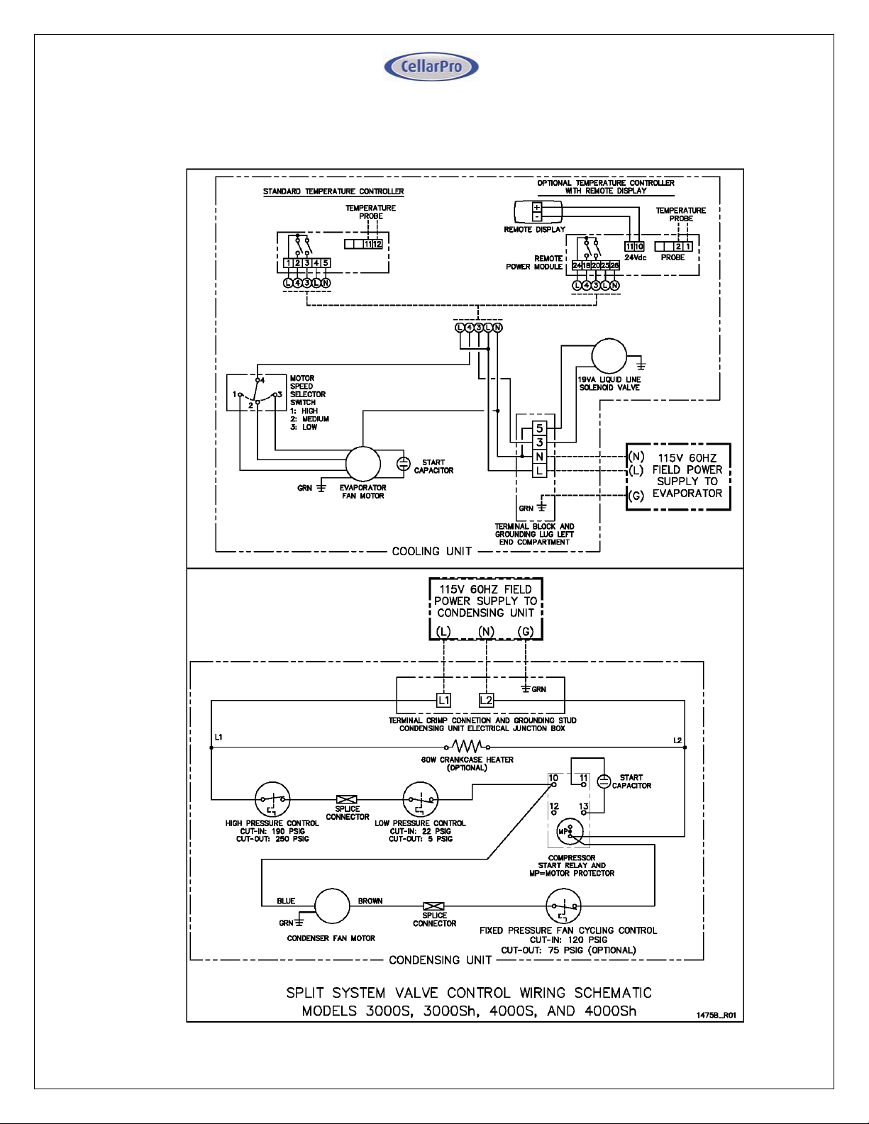
Wiring Diagrams – Option A: Dual Power / Valve Control
Models 3000S, 3000Sh, 4000S, 4000Sh
17 V10.14
Page 18
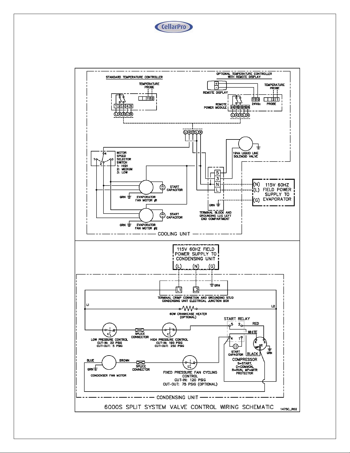
Wiring Diagrams – Option A: Dual Power / Valve Control
Model 6000S
18 V10.14
Page 19
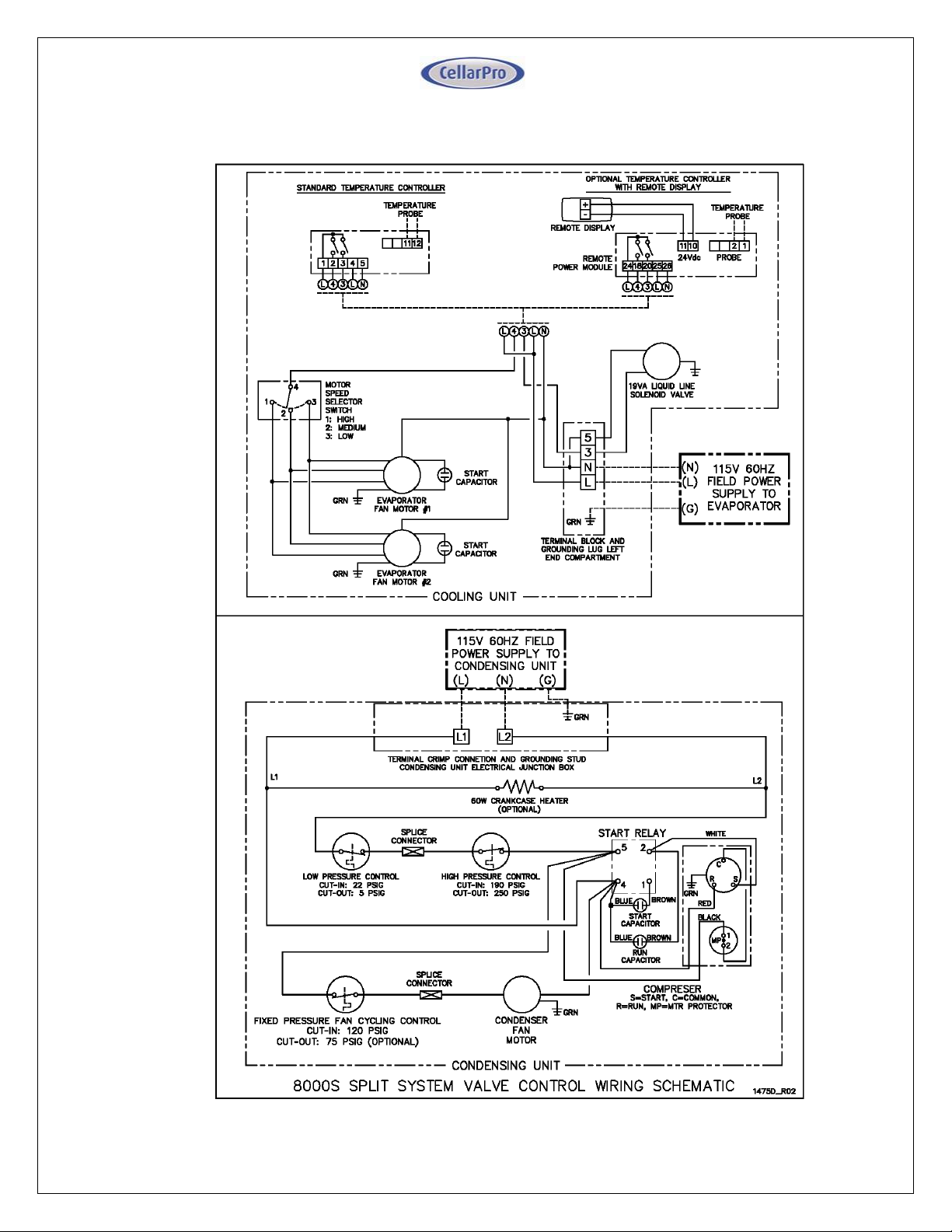
Wiring Diagrams – Option A: Dual Power / Valve Control
Model 8000S
19 V10.14
Page 20
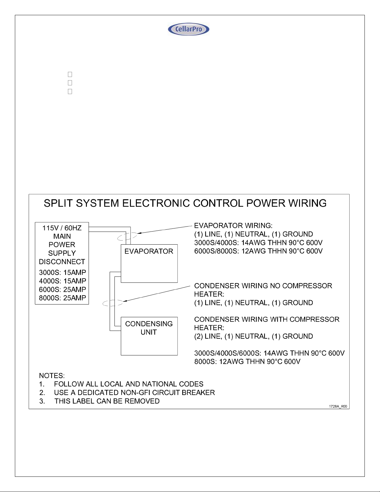
System Wiring – Option B: Single Power / Electronic Control
Under this configuration, only the Evaporator is powered by the Field Power Wiring,
as follows:
Connect line lead to Evaporator terminal "L"
Connect neutral lead to Evaporator terminal "N"
Connect power ground to grounding lug on Evaporator
The Condensing Unit is powered by connecting it to the Evaporator, is follows:
"3" on the Evaporator to "L1" on the Condensing unit
"5" on the Evaporator to "L2" on the Condensing unit
Ground lug on the Evaporator to the grounding stud on the Condensing unit.
With optional crankcase heater: Run a separate lead connecting “L” on
Evaporator to “C” on Condensing Unit.
20 V10.14
Page 21
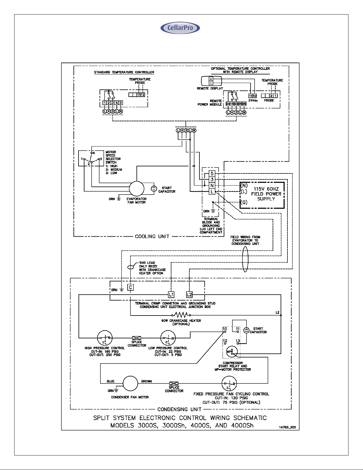
Wiring Diagram – Option B: Single Power / Electronic Control
Models 3000S, 3000Sh, 4000S, 4000Sh
21 V10.14
Page 22
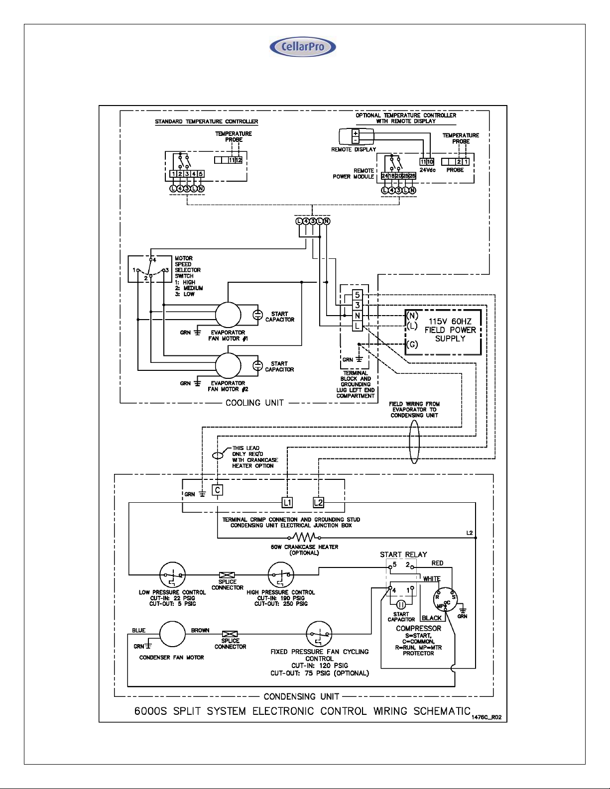
Wiring Diagram – Option B: Single Power / Electronic Control
Models 6000S
22 V10.14
Page 23
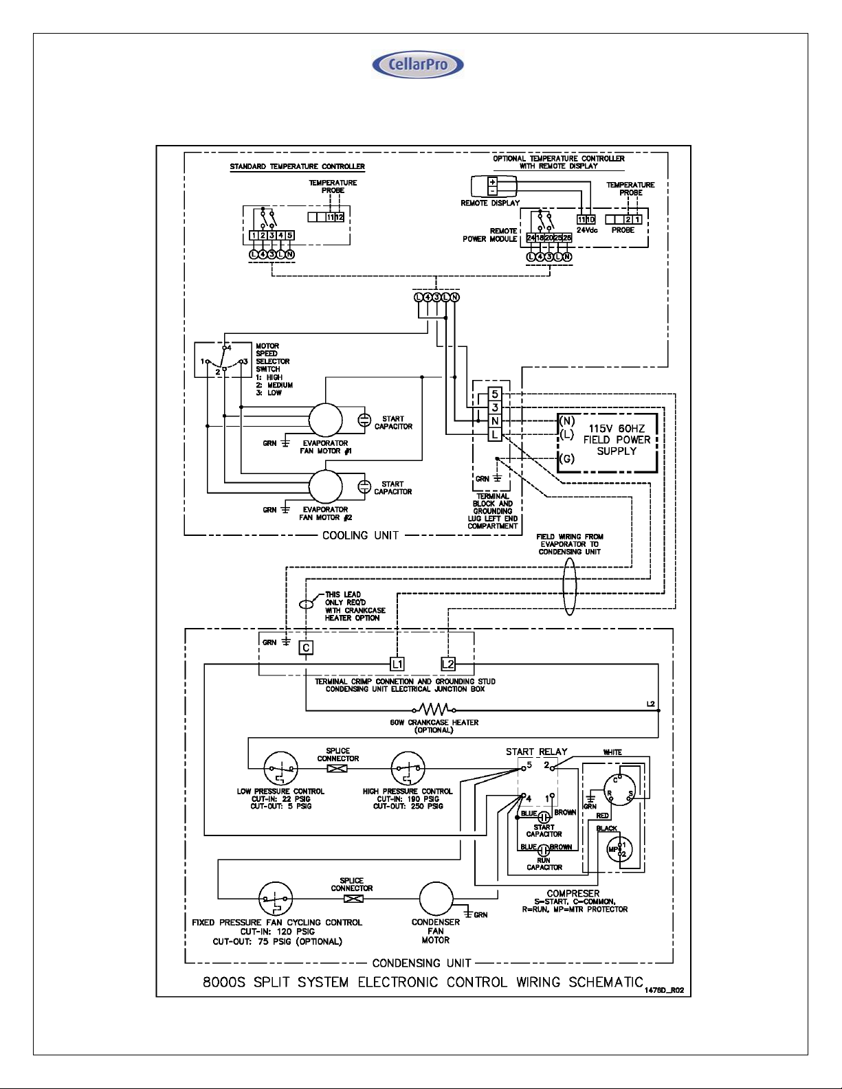
Wiring Diagram – Option B: Single Power / Electronic Control
Models 8000S
23 V10.14
Page 24
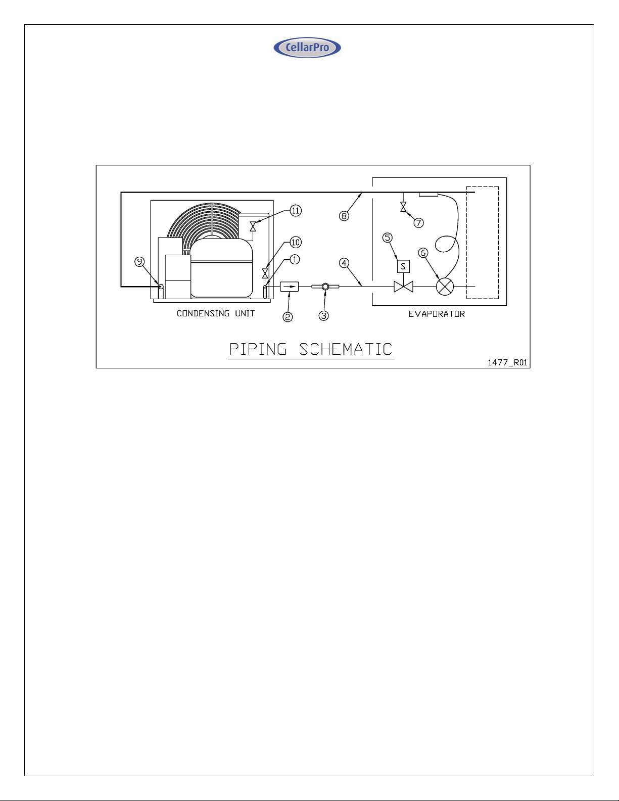
Installing Refrigeration Lines
The Evaporator and Condensing units should be piped according to the following
piping schematic:
Piping Legend
1. Liquid connection location.
2. Hermetic liquid line filter drier (shipped loose). Install with the directional flow
arrow as shown.
3. Liquid line sight glass with moisture indicator (shipped loose).
4. Liquid line refrigeration piping in accordance with Line Sizing Chart.
5. Factory installed liquid line solenoid valve (normally closed) (Dual
Power/Valve Control configurations only).
6. Factory installed thermostatic expansion valve. Bulb must be attached to a
horizontal run of the suction line after brazing the field suction connection, and
insulated with the supplied cork tape.
7. Factory installed ¼” evaporator suction access valve.
8. Insulated suction line refrigeration piping (refer to Line Sizing Chart below).
9. Suction connection location.
10. Condensing unit ¼” liquid access valve. The position of the access valve
varies by model, trace the liquid line back from the connection through the
receiver to the condenser coil bottom outlet to locate the valve.
11. Condensing unit ¼” suction access valve located off a tee on the compressor
shell process tube.
24 V10.14
Page 25
Split System Line Sizing Chart
Model
Liquid Line
Size ("ODS)
Up to 100
feet
Minimum
Suction Line
Insulation
Thickness
(in)
Up to 25 feet
Over 25 feet
up to 50 feet
Over 50 feet
up to 100 feet
3000S/Sh 1/4 1/2 1/2 1/2 1/2
4000S/Sh 3/8 1/2 1/2 1/2 1/2
6000S 3/8 1/2 1/2 5/8 5/8
8000S 3/8 5/8 5/8 5/8 7/8
Notes:
1) Line lengths are expressed in equivalent feet = actual run length + fitting allowances.
3) Use only dehydrated refrigeration service tubing and refrigeration grade fittings.
4) Install refrigeration piping in accordance with local codes and ASHRAE guidelines.
Suction Line Size by Length ("ODS)
2) Chart includes allowances for Fittings, Filter Drier, and Sight Glass.
Line Sizing Chart
Refer to the Line Sizing Chart below for selecting the appropriate tubing size for
the length of the piping run. Note that the recommended line size may not match
the connection ports on the Condensing unit and the Evaporator. Refrigeration
grade fittings must be supplied by the installing technician to make the necessary
transitions. Transitions should be made as close to the unit as possible.
Suction line routing must be designed to ensure oil return to the Condensing unit.
Vertical Piping Guidelines
Piping runs should be kept as short and compact as possible. Low-lying areas (oil
“traps”) where oil can accumulate should be avoided. Refer to the following
guidelines with regards to the vertical placement of the evaporator and condensing
units:
25 V10.14
Page 26
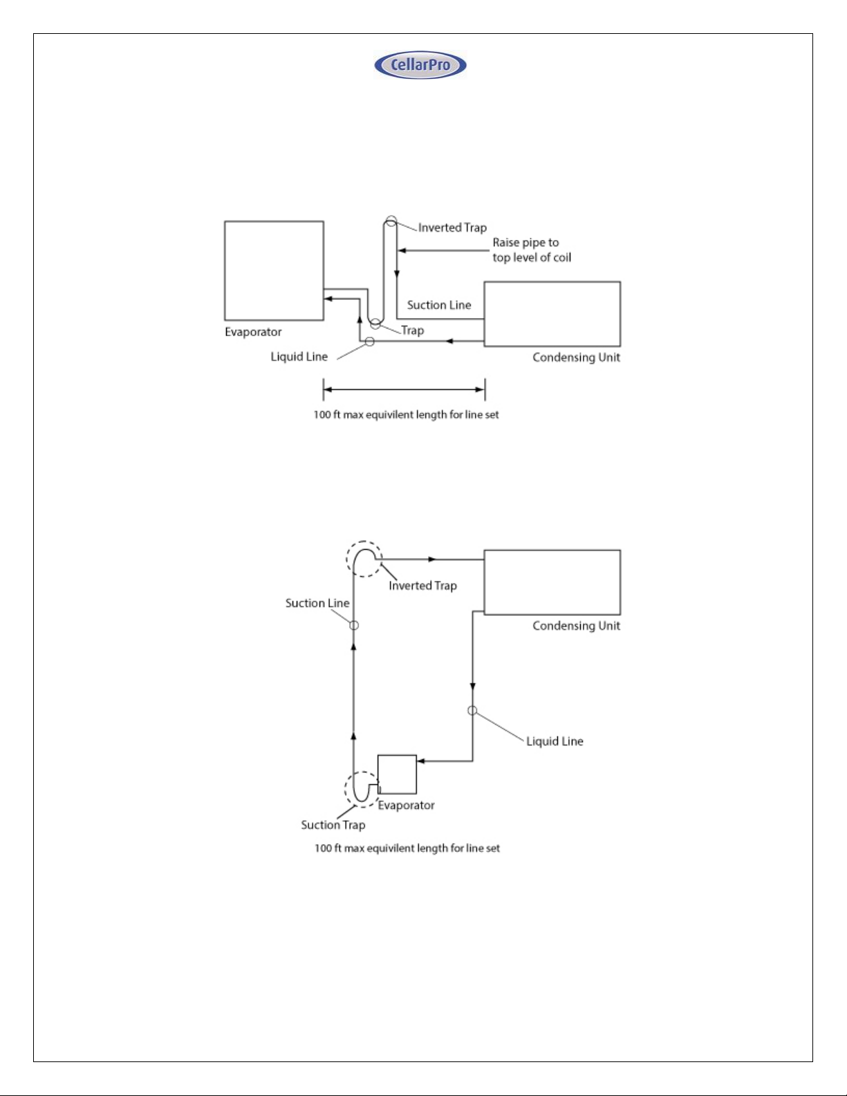
1. When the evaporator and condensing unit are located on the same level,
pipe suction line with inverted trap as shown to prevent liquid migration to the
compressor during the off cycle. Pitch the suction line slightly downward to
the condensing unit:
2. When the evaporator is located below the condensing unit, a suction trap
must be installed at the evaporator, and an inverted trap must be installed at
the condensing unit, for proper oil return, as follows:
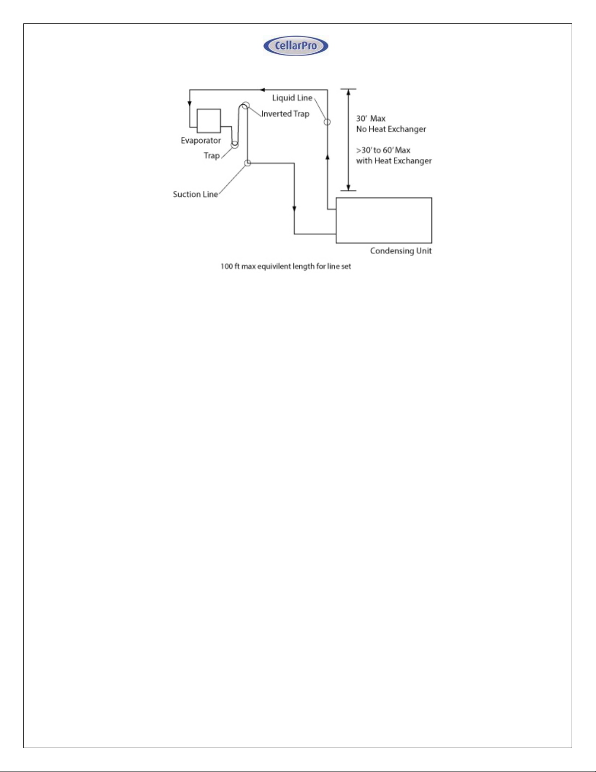
3. When the evaporator is located above the condensing unit, pipe suction line
with inverted trap as shown to prevent liquid migration to the compressor during
the off cycle. The vertical lift of the liquid line is limited to 30 feet. The lift may be
increased to 60 feet if an optional liquid/suction Heat Exchanger is added to the
field piping.
26 V10.14
Page 27
Evacuation, Leak Detection, and Charging
Important note: The condensing unit and evaporator are shipped with a nitrogen
holding charge. Please verify positive pressure through the access valve prior to
installation. If you cannot verify the holding charge, please contact Cellarpro at
707.794.8000.
Once the piping is installed, the following steps should be performed to ensure a
dry and leak-free system:
1. The Condensing unit is pre-charged with compressor oil. To avoid moisture
contamination of the oil, do not leave the system open to atmosphere for more
than 15 minutes.
2. Dual Power Source / Valve Control Systems Only: Supply power to the
Evaporator only - DO NOT connect power to the Condensing unit. Turn on the
temperature controller, which will energize and open the liquid line solenoid
valve. Verify the solenoid is powered as indicated by the compressor icon
("snowflake") on the temperature controller display.
3. Pressurize the system to a maximum of 150PSIG of dry nitrogen. It is important
to add nitrogen though both the high and low side access valves on the
condensing unit to make sure the system is fully pressurized. Mark the
pressure and hold for a minimum of 1 hour. If the pressure holds, proceed to
the next step, otherwise locate and repair the leak and repeat this step.
4. Evacuate the system to a minimum of 500 microns. It is important to pull a
vacuum though both the high and low side access valves on the condensing
unit to make sure the system is fully evacuated. If the vacuum is achieved,
proceed to the next step, otherwise locate and repair the leak and repeat from
step 4.
27 V10.14
Page 28
5. Disconnect the vacuum pump, but leave the system under vacuum. Use a
charging scale to accurately weigh in the refrigerant. Charge liquid R-134a
refrigerant through the liquid service valve according to the charge pounds
indicated in the "System R-134a Charge Guidelines" chart below. Additional
refrigerant may need to be added, using the steps outlined below. DO NOT
USE REFRIGERANT WITH ADDITIVES.
6. Important: The most common causes of compressor failure are
refrigerant overcharge, adding liquid refrigerant through the suction
access valve, and cold compressor starts. If your system is equipped with
a compressor heater, make sure this is wired to be energized even when the
system is idle. If starting up the system in a cold ambient, or if the system has
been sitting idle without the compressor heater energized for more than 24
hours, it is critical to warm the bottom shell of the compressor above the
ambient temperature for 30 minutes to drive excess refrigerant out of the
compressor oil.
7. Connect power to the Evaporator and Condensing unit, and activate the
system. IMPORTANT: If the system does not power up after the 3 minute
start up delay, verify field wiring according to the appropriate wiring
diagram. If correct, disconnect power from the system and contact
Cellarpro at 707.794.8000.
Measure pressures and temperatures to verify the system is within normal
operating limits as indicated on the Split System Data Sheet. A loose copy of
the Data Sheet is provided with the unit, and an additional copy is included at
the end of this manual. The condensing pressure must be above 105 PSIG
when taking these measurements. In a low ambient environment, it may be
necessary to temporarily block off the condenser air intake to force the
condensing pressure higher. Do not run the system if the suction superheat at
the condensing unit is below 20°F.
8. It may be necessary to slightly adjust the charge amount after weighing in the
recommended initial charge. 1) Not enough refrigerant: If the Evaporator is not
providing enough cooling, the system may be undercharged. If liquid
subcooling is below 10°F and the suction superheat is well above the minimum
of 20°F, slowly add vapor refrigerant though the suction service valve until the
subcooling is within specifications. 2) Too much refrigerant: If the suction
superheat is below 20°F, remove refrigerant until the superheat is above this
minimum limit.
9. (Optional) It should not be necessary to manually adjust the thermostatic
expansion valve superheat from the factory default setting. However if desired,
the superheat may be adjusted as follows: 1) Remove the cork tape insulation
from the expansion valve body to locate the cap on the superheat stem, and
unscrew the cap using a 5/32 in. Allen wrench. 2) Using a 5/32 in. Allen wrench,
locate the setting spindle inside the superheat stem and make superheat
adjustments ¼ turn at a time (¼ turn≈1°F). Turning clockwise increases
superheat. Turning counter-clockwise decreases superheat. The target
superheat at the evaporator is 10°F +/- 2°F. 3) Reinstall the cap and cork tape
insulation.
28 V10.14
Page 29
10. Confirm that the compressor, condenser fan, and evaporator fan(s) are
energized. Allow the system to balance for 30 minutes, then record all readings
on the Data Sheet and submit to CellarPro for warranty activation review.
11. Observe that the condensing unit turns on when the “snowflake” icon on the
temperature display is lit solid (not blinking), and turns off when the “snowflake”
icon turns off. It may be necessary to temporarily raise the set point to force
the unit to cycle off. If the condensing unit does not cycle on/off in conjunction
with the “snowflake” icon, please contact the factory for assistance.
Installation Tips and Guidelines
Make sure all electrical connections are secure.
Inspect Evaporator and Condensing unit fans to confirm airflow. There shouldn’t
be any excessive vibration, noise or obstructions to airflow.
Observe system pressures and temperatures during charging and initial
operation and keep note of them as they will be required for the Service and
Support Data Sheet which initiates the warranty.
Do not overcharge or use refrigerant with additives.
Remember that bubbles in a sight glass may be caused by a restriction as well
as a shortage of refrigerant. A properly charged system may still have small
bubbles visible in the sight glass, so use actual superheat and subcooling
readings to charge the system.
Do not leave unit unattended until the system has reached normal operating
conditions, and the system has been observed properly cycling on/off to the
desired set point and differential.
Make sure all access valve caps are in place and tight.
29 V10.14
Page 30
System R-134a Charge Guidelines
Actual
Line
Length
System Charge (lbs) by Model #
(ft) 3000S/Sh 4000S/Sh 6000S 8000S
5 1.38 1.65 2.31 3.71
10 1.46 1.85 2.51 3.92
15 1.54 2.05 2.71 4.12
20 1.61 2.25 2.93 4.32
25 1.69 2.45 3.13 4.53
30 1.77 2.65 3.34 4.73
35 1.85 2.85 3.54 4.93
40 1.93 3.05 3.74 5.14
45 2.01 3.25 3.95 5.44
50 2.09 3.45 4.15 5.65
55 2.16 3.65 4.36 5.86
60 2.24 3.85 4.56 6.08
65 2.32 4.05 4.76 6.29
70 2.40 4.25 4.97 6.51
75 2.48 4.45 5.17 6.72
80 2.56 4.65 5.37 6.93
85 2.64 4.85 5.58 7.15
90 2.71 5.05 5.78 7.36
Note:
1) Actual charge may vary - follow charging instructions
detailed under Item 6 in the section titled Evacuation,
Leak Detection, and Charging (above).
2) Lines sized according to Line Sizing Chart assuming actual
line length plus 10 equivalent feet for fittings losses.
System R-134a Charge Guidelines
30 V10.14
Page 31
We also offer a remote control panel kit that can be installed remotely (up to 10
feet) from the cooling unit, either inside or outside the cellar, and a bottle probe (10
foot cord) that can be plugged into the cooling unit.
Summary
Keep in mind the following guidelines before purchasing a wine cooling unit from
CellarPro:
If the cellar is too large for the cooling unit, the cooling unit will be unable to
maintain proper, even temperatures inside the cellar.
Without proper insulation and an airtight environment, the cooling unit
effectively will become a de-humidifier and potentially will produce buckets of
water.
Without access to cool air, either because of improper ventilation
or because the environments is too hot, the cooling unit will be unable to
maintain proper temperatures inside the cellar.
When the cooling unit will be exposed to temperatures below 40°F, a
compressor heater must be added to protect the compressor.
Under any of the above conditions, the unit’s internal components may become
damaged, the expected useful life of the wine cooling unit may be adversely
affected, and the product’s warranty may become null and void.
31 V10.14
Page 32
IV. Operating Instructions
Overview
CellarPro cooling units are designed to maintain optimal conditions for wine storage
and aging. These conditions include steady, cool temperatures, high humidity,
minimal vibration and light, and clean air.
The settings on your CellarPro cooling unit have been preset and optimized by the
factory. Before changing any settings below, we recommend waiting 14 days to allow
the cooling unit to “break in.”
The cooling unit is designed to cool the cellar gently without stripping moisture out of
the cellar environment. Therefore, it is not uncommon for the cooling unit to run
nonstop for up to a week initially, depending on the temperature inside the cellar, the
size of the cellar, and the temperature of the ambient environment. Once the cellar
has reached equilibrium, it is normal for the cooling unit to run as much as 75
percent of the time.
CellarPro cooling units are designed to maintain optimal temperatures for storing and
aging fine wine. CellarPro cooling units are not designed to maintain temperatures
for serving wine, which tend to be much colder than storage temperatures, especially
serving temperatures for white and sparkling wines.
CellarPro cooling units must be used, stored, moved and/or shipped in the
upright position. Be careful when turning the unit on its side. The unit NEVER
should be turned upside down.
Temperature Control
CellarPro cooling units are designed to turn “on” when the air temperature passing over
the evaporator coils inside the cellar exceeds the Minimum Set Point plus the
Temperature Differential, and turn “off” when the temperature drops below the
Minimum Set Point. For example, if the Minimum Set Point is 58°F and the
Temperature Differential is 4°F, the cooling unit will turn on when the
temperature rises above 62°F inside the cellar, and it will turn off when the
temperature falls below 58°F. In this example, the average temperature inside the
cellar will be 60°F.
Basic Operation
The cooling system is programmed with a 3-Minute Delay at Startup to protect its
internal components. The temperature inside the cellar can be increased or
decreased by changing the Minimum Set Point as described later in this chapter. If
the cooling unit runs too much, you can raise the Minimum Set Point to reduce the cycle
“on” time. Most wine collectors store their wine in the range of 55 - 60°F.
CellarPro cooling units are designed to maintain appropriate levels of humidity,
ranging from 50 to 70 percent, inside wine cellars. In order to increase or decrease
32 V10.14
Page 33
humidity inside the cellar, the
Fon
setting can be changed as described in the
“Advanced Operation” section later in this chapter.
Switch Instructions
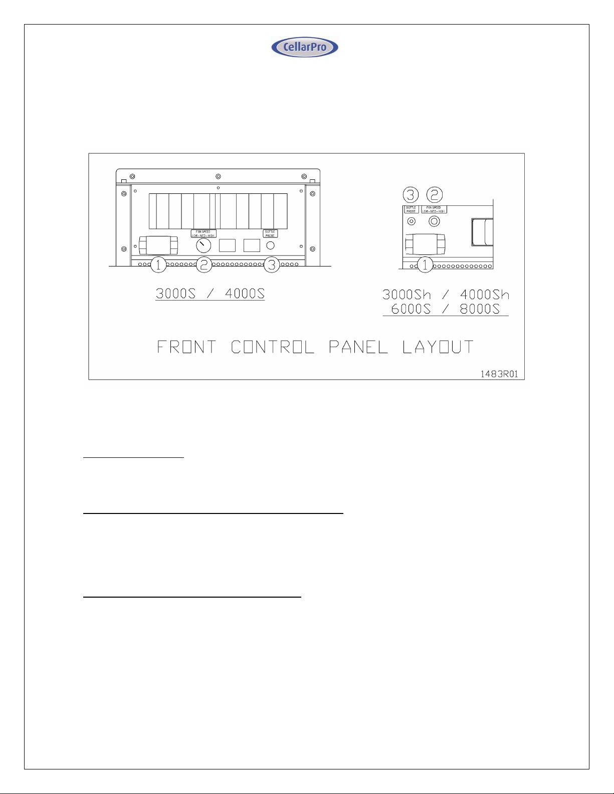
(1) Control Panel: Maintains desired cellar environment. Factory settings are
optimized for peak performance. Controller is described in detail in the following
section.
(2) Fan Speed Selector Switch (Low/Med/High): The cooling unit fans operate on 3
speed settings: Low, Medium, and High. For optimum sound and energy efficiency,
select the lowest fan speed that will maintain the desired cellar temperature. High
speed is recommended for initial cellar pull down, extreme temperature conditions
and ducted installations.
(3) Bottle Probe Jack (Bottle Probe): Plug in the remote bottle probe (sold
separately) to control the cellar by liquid temperature rather than air temperature
inside the cellar. Disconnecting the probe will automatically return the control to air
temperature. When using a bottle probe, the Temperature Differential will need to
be adjusted to 1 as shown in the “Advanced Operation” instructions below.
33 V10.14
Page 34
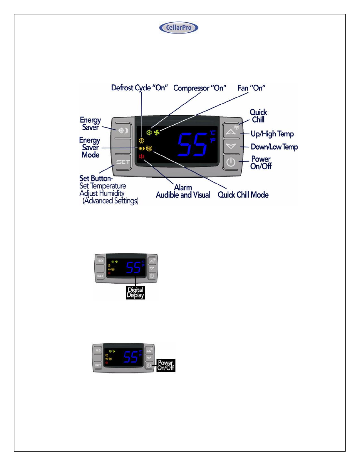
Digital Display
The temperature displayed on the control
indicates the real-time air temperature as
measured by Probe 1 (P1) located behind
the front grill of the cooling unit.
Power “On” / “Off”
Press “Power On/Off” to turn the unit on
and off.
When the “Compressor On” indicator light
is on, the Compressor is running.
When the “Fan On” indicator light is on,
the Fan is running.
The cooling system is programmed with a 3-
Minute Delay at Startup to protect its internal
components.
Control Panel Instructions*
34 V10.14
Page 35
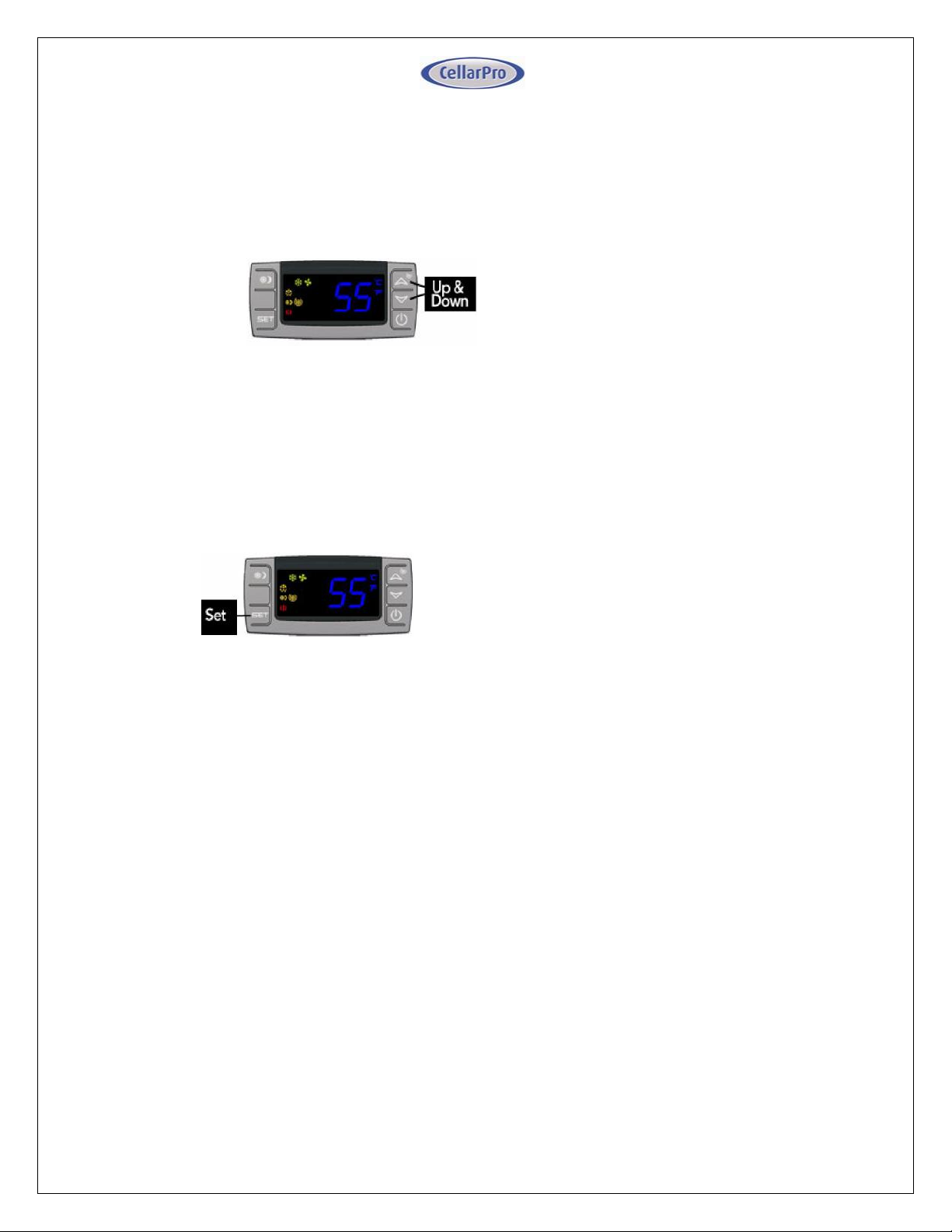
Up and Down Buttons
To view the “High Temp” recorded by the
cooling unit, press the “Up” button once.
To view the “Low Temp” recorded by the
cooling unit, press the “Down” button once.
To reset the “High Temp” or “Low Temp”,
press the “Set” button for three seconds
while “Hi” or “Lo” is displayed. “RST” will
blink three times to indicate confirmation.
Set Button
The cooling unit is factory preset with a
Minimum Set Point of 58°F and a
Temperature Differential of 4°F. This means
that the cooling unit will turn on when the
display rises above 62°F (58°F + 4°F), and
turn off when the display falls below 58°F.
In this example, the average temperature
inside the cellar will be 60°F.
To view the Minimum Set Point, press the
“Set” button for one second.
To change the Minimum Set Point,
Press the “Set” button for three
seconds until °F” blinks
Press “Up” or “Down” button
Press “Set” button to confirm
The “Set” temperature will blink three times
to indicate confirmation
The recommended Minimum Set Point
range is 53 - 60°F. To change the
Temperature Differential, see “Advanced
Operation” later in this chapter.
* Remote display/control instructions are included following this section.
35 V10.14
Page 36
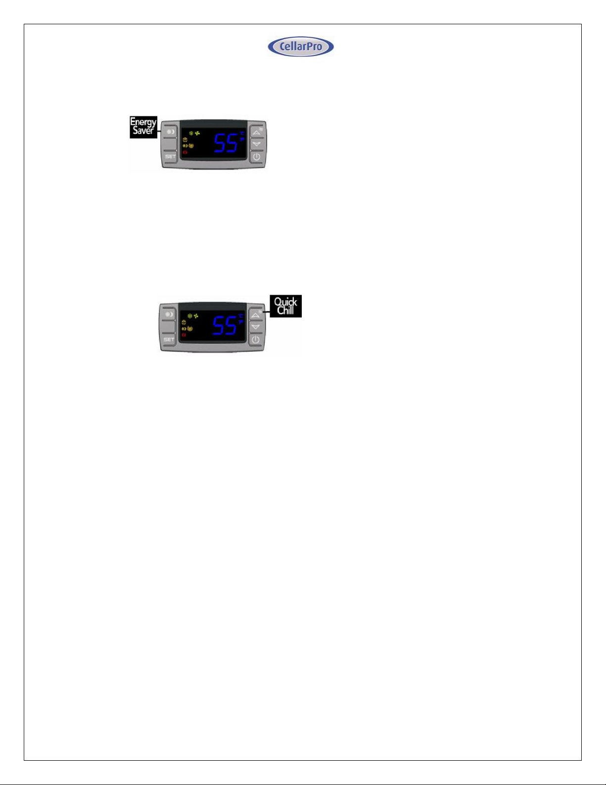
Energy Saver Button
To activate and deactivate the “Energy
Saver” mode, press the “Energy Saver”
button.
The “Energy Saver” indicator light will turn
on when the cooling unit is in “Energy
Saver” mode.
In “Energy Saver” mode, the Minimum Set
Point increases 4°F and the Temperature
Differential is unchanged.
Quick Chill Button
To activate the “Q u ick Ch ill” mo de,
press t h e “Up” / “Quick Chill” button for
three seconds.
To deactivate “Quick Chill”, press “Quick
Chill” button for three seconds again.
The “Quick Chill” indicator light will turn on
when the cooling unit is in “Quick Chill”
mode.
In the “Quick Ch ill” mode, the co oling unit
will run continuously for 6 hours (or until the
intake temperature registers 50°F). This
mode is useful after loading “warm” bottles in
a cellar
36 V10.14
Page 37
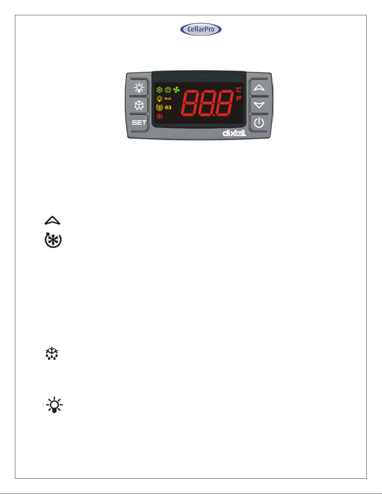
Digital Display
The temperature displayed on the control is red instead of blue.
Quick Chill
Button
Button
Icon
To activate the “Quick Chill” mode, press the “Up” button for three
seconds
To deactivate “Quick Chill”, press the “Up” button for three seconds
again
The “Quick Chill” indicator (Row 3) light will turn on when the cooling unit
is in “Quick Chill” mode,
In the “Quick Chill” mode, the cooling unit will run continuously for 6 hours
(or until the unit reaches set point.). This mode is useful after loading
“warm” bottles in the cabinet.
Auto Defrost
Mode
The cooling unit has a factory default defrost cycle that initiates every
16 hours for 20 minutes. When the cooling unit is in auto-defrost mode,
the “Defrost” Indicator light (Top row) will turn on, and the evaporator
fan will run.
Manual Defrost
Hold the defrost button in for 3 seconds to initiate a manual defrost. The
“Defrost” Indicator light (Top row) will turn on for a 20 minute defrost
cycle.
Light
The light button function is disabled, however pressing it will turn on/off
the light indicator on the display (2nd row).
Energy Saver
The remote display is not configured with an Energy Saver mode. The
set point can be raised manually for periods where energy savings is
desired.
Remote Control / Display Instructions
37 V10.14
Page 38
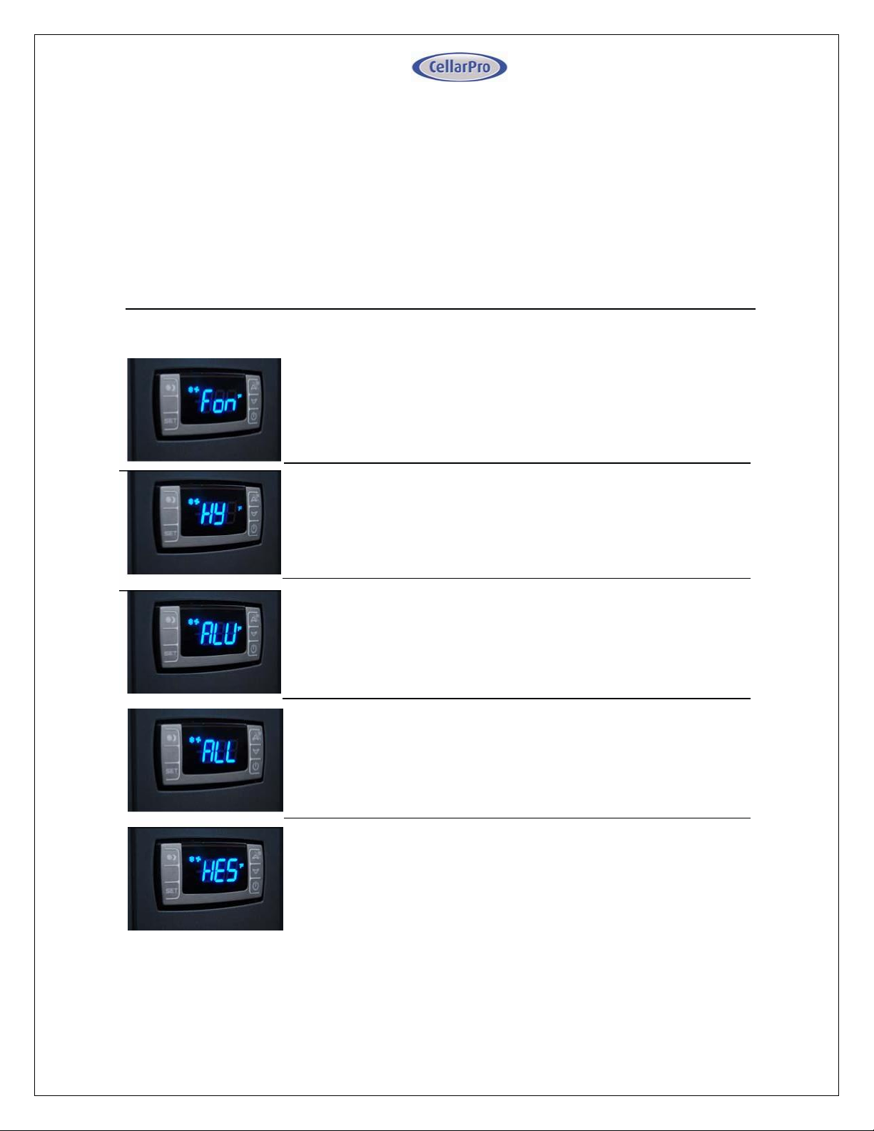
LOW TEMPERATURE ALARM: The factory preset for this
setting is “45”.
This setting designates the Low temperature inside the cellar
at which the alarm is triggered. We recommend leaving this
setting at the factory preset.
ENERGY SAVINGS MODE DIFFERENTIAL: The factory preset
for this setting is “4”.
This setting controls the Temperature Differential for the
Energy Savings Mode. The recommended range for this
setting is 2-4.
HUMIDITY: The factory preset for this setting is “3”.
If the humidity inside the cellar is too low, press the “Set”
button, then use the “Up” button until the desired setting is
reached. The recommended range for this setting is 0-6.
TEMPERATURE DIFFERENTIAL: The factory preset for this
setting is “4”.
This setting determines the Temperature Differential and
therefore the temperature at which the cooling unit will cycle
on. The recommended range for this setting is 4 or 5.
HIGH TEMPERATURE ALARM: The factory preset for this
setting is “70”.
This setting designates the High temperature inside the
cellar at which the alarm is triggered. We recommend leaving
this setting at the factory preset.
Advanced Operation
CellarPro cooling systems can be programmed with advanced settings to achieve
more control over conditions inside the cellar. Conditions like humidity, the
Temperature Differential, and alarm settings all can be modified for custom
applications. To access the advanced settings, do the following:
Press the “Set ” butt on and the “Down ” b utton t oget her at the same time, an d
hold for three seconds. Then, use the “Up” or “Down” button to scroll to the following
screen:
38 V10.14
Page 39
V. Troubleshooting
Improper installation, inadequate insulation, or a cellar that is too large will
cause the cooling unit to run continuously and be difficult to troubleshoot.
The cooling unit is designed to turn on when the air temperature in the cellar rises
ABOVE the Minimum Set Point + Temperature Differential, and turn off when the air
temperature falls below the Minimum Set Point. For example, if the Minimum Set
Point is 58°F and the Temperature Differential is 4°F, the cooling unit will turn above 62°F
and turn off below 58° F. In this example, the average temperature inside the cellar will
be 60°F.
Cooling Unit Runs Constantly
When bottles are first loaded in the cellar, the cooling unit will run continuously (even
up to a week) until the temperature inside the cellar falls below the Set Point.
Hot weather conditions, insufficient ventilation and/or dirty condenser filters may cause
the cooling unit to run continuously. To reduce cycle times,
1. Remove any obstructions to air flow to or from the unit
2. Check to make sure the condenser filter is clean
3. Increase the supply of cool air to the space outside the condenser coils, using a fan,
ducting or an exhaust system to remove heat from the space.
4. Raise the Minimum Set Point on the cooling unit
Cooling Unit Is Dripping
The cooling unit is designed to remove excess moisture from inside the cellar, which
collects in the drip pan of the cooling unit and is evaporated by the condensate heater.
Excess moisture can occur when the cooling unit runs constantly, when the Minimum
Set Point is too low and/or when the cellar doesn’t have a good seal from the outside
environment. To eliminate overflow, do the following:
1. Ensure the condensate overflow drain line is not blocked, that the drain line is trapped
and the trap is filled with water.
2. Ensure there is a downward pitch in the drain line from the outlet at the unit drain pan
to the final drain. It may be necessary to install a trap vent as detailed in the
Condensate Drain Line installation section.
3. Check that the cellar has airtight seals, including the door(s), light fixtures, and all
walls, ceiling and floor.
4. Raise the Minimum Set Point of the cooling unit.
The Cooling Unit Won’t Turn On
The cooling system is programmed with a 3-Minute Delay at Startup to protect its
internal components.
39 V10.14
Page 40
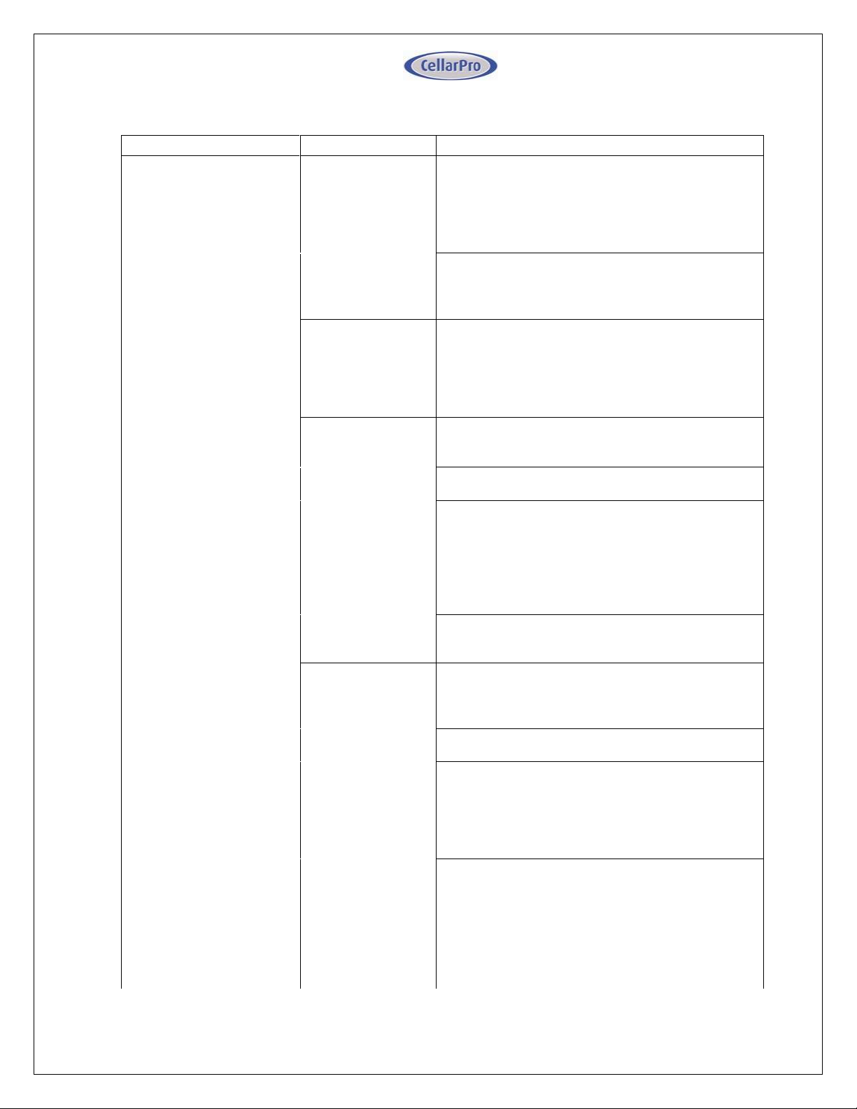
Issue
Possible Causes
Potential Solutions
No cooling: no refrigerant
flow.
If the "snowflake" icon is
illuminated on the
temperature display
control, the compressor
should be running.
Electronic Control:
No power to
evaporator
Valve control: no
power to liquid
solenoid valve coil
Power supply to Evaporator interrupted. Restore
power.
(Valve control only) Power supply to solenoid coil
interrupted: loose wire. Inspect for loose fan
wiring and reconnect.
Solenoid coil
failure (Valve
control option only)
When the Evaporator is powered on and off, a
distinct "click" should be heard indicating the
opening/closing of the solenoid valve. If not, the
solenoid coil may need to be replaced. Consult
factory.
No power to
compressor
Power supply to Condensing Unit interrupted.
Restore power.
Check for loose wires and reconnect.
Low pressure switch is open: On Valve control
systems, make sure solenoid is energized.
Jumper out switch to check for a faulty switch,
and replace if necessary. Note that in
installations below 0°F this switch may remain
open. Consult factory.
High pressure switch is open: refer to the "High
Pressure Safety Shutdown" section.
High pressure
safety shutdown /
high discharge
pressure
Locate and correct source of high condensing
head pressure:
Refrigeration line blockage
Condenser fan not operating in ambient
temperatures above 90°F. Ensure that there is
power to the Condensing Unit and verify the fan
cycling control settings. Replace condenser fan
and fan cycling control if necessary.
Insufficient ventilation: reference Condensing
Unit installation guidelines for proper placement
and ambient temperature requirements. Correct
to ensure adequate air ventilation to and from the
Condensing Unit.
Improper refrigerant charge: inspect for over-
charged system or non-condensables in system.
Other Troubleshooting Issues
40 V10.14
Page 41
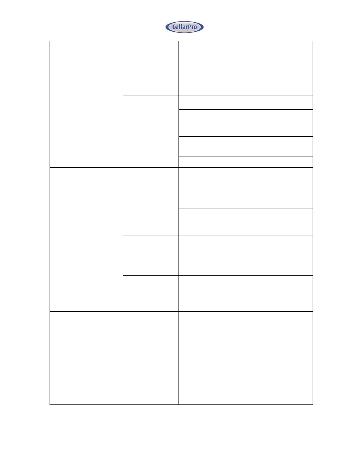
Issues
(Cont.) No cooling: no
refrigerant flow.
If the "snowflake" icon is
illuminated on the
temperature display
control, the compressor
should be running.
Possible Causes
Potential Solutions
(Cont.) High
pressure safety
shutdown / high
discharge
pressure
Dirty or obstructed condenser coil: clean and
remove all obstructions to airflow.
Intermittent power
to compressor
Check for loose wires and secure.
Compressor cycling on internal thermal overload
protection. Replace start capacitor/relay
assembly
Compressor cycling on high pressure - see "High
pressure safety shutdown" section.
Faulty compressor. Consult factory.
No cooling: Evaporator
fan not blowing.
If the "fan" icon is
illuminated on the
temperature display
control, the fan should be
blowing air.
No power to fan(s)
Power supply to Evaporator interrupted. Restore
power.
Power supply to fan interrupted: loose wire.
Inspect for loose fan wiring and reconnect.
Fan capacitor: check for loose wires or out of
spec capacitance. Reconnect loose wires or
replace capacitor(s).
Fan obstructed
With power to unit disconnected, check the
rotation of the blower fan. If fan does not spin
freely, inspect for and remove obstructions. If no
obstructions are found, the fan may need to be
replaced. Consult factory.
Fan running but
not drawing air
through coil.
Fan short cycling: Make sure all housing panels
are attached to the unit. Replace missing panels.
Coil is blocked with ice. Refer to the "Iced coil"
section.
Iced coil
Temperature
displayed is higher
than actual cellar
temperature
If using a bottle probe, check placement and
compare to actually cellar temp. Relocate probe
if necessary to better correlate to actual cellar
temperature.
Probe fault: check for loose connections if
splices were added in the field.
Moisture in bottle probe jack: Can cause high
readings, consult factory for solution.
41 V10.14
Page 42
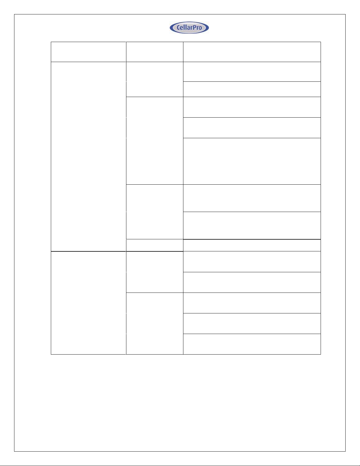
Issues
Possible Causes
Possible Solutions
(Cont.) Iced Coil
Low refrigerant
charge
System charged incorrectly. Review process and
correct.
Leak in system. Find and repair leak, recharge
system.
Mal-functioning
thermostatic
expansion valve.
Incorrect superheat setting: determine superheat
and adjust. If expansion valve is faulty, replace.
Expansion valve bulb not located correctly review installation instructions and correct.
Liquid flashing at the expansion valve inlet. See
"High liquid line pressure drop" section.
Condensing unit
never shuts off
System is wired incorrectly. Locate correct wiring
diagram for “Electronic” or “Valve” controlled
system, trace wiring and correct.
If a “Valve” control system, the low pressure
switch may have failed closed. Check switch and
replace if necessary.
No airflow
See "Evaporator fan not blowing" section
Insufficient liquid subcooling
Low refrigerant
charge
System charged incorrectly. Review process and
correct.
Leak in system. Find and repair leak, recharge
system.
High liquid line
pressure drop
Check for plugged filter drier and replace if
necessary.
Inspect pipe routing for proper piping practices
and correct.
Liquid line picking up too much ambient heat may need to insulate.
42 V10.14
Page 43
Alarm
What it means
What to do
P1
Probe 1, which senses the
temperature inside the cellar and
controls the on/off cycles of the
cooling unit, has failed
The cooling unit enters a timed autocycle mode until Probe 1 is repaired or
replaced. In this mode, the cooling unit
will turn on for 12 minutes and off for 8
minutes.
Please call CellarPro at 877.726.8496
to repair or replace Probe 1
HA
The temperature inside the cellar
is too warm (above 70°F for more
than 1 hour)
Check if the cellar has a leak
Check if door was left open
Lower the ambient temperatures
LA
The temperature of the cellar is
too cold
(below 45°F)
Raise the Minimum Set Point to 60°F
Raise the ambient temperature
Maintenance
The condenser coils on the Condensing unit will collect dust, dirt and lint over time. If
the condenser coils become clogged, the cooling unit will not have proper airflow
and its performance and longevity will be compromised. The condenser coils
themselves also can be cleaned with a vacuum cleaner – ideally with a brush
attachment to loosen dust caught between the fins.
Alarms
The cooling unit has both an audible notification and a visual alarm indicator (shown in
“red” on the control panel) that are activated when an alarm is triggered.
Please note
:
the temperature alarms (HA and LA) are disabled during the first 23 hours of operation
after the cooling unit is plugged in and/or turned on.
The control panel also will flash a code for each alarm, as follows:
43 V10.14
Page 44
VI. Limited Warranty
For five years from the date of original delivery, your CellarPro warranty covers the
internal compressor if it proves to be defective in materials or workmanship. In
addition, for two years from the date of original delivery, your CellarPro warranty
covers all parts and labor to repair or replace any components in the wine cooling unit
that prove to be defective in materials or workmanship. The warranty will not be
activated until the Support and Data Service Sheet has been completed and submitted
to CellarPro. The warranty period starts from the time of purchase, regardless of the
time of activation.
Under the terms of this warranty, CellarPro will repair or replace the original cooling
unit with a new or refurbished cooling unit and, once replaced, the original cooling
unit must be returned to CellarPro.
All service provided by CellarPro under the above warranty must be performed by a
designated repair center, unless otherwise specified by CellarPro. Purchaser is
responsible for shipping the cooling unit to and from CellarPro or to and from a
designated repair facility, and for removing and reinstalling the cooling unit from the
wine cellar.
The limited warranty applies only to cooling units purchased from the factory or an
authorized dealer. Damage caused by others or by any cause beyond the control of
CellarPro, shall not be considered defects in material or workmanship and are not
covered by the warranty. The limited warranty does not cover any parts or labor to
correct any defect caused by negligence, commercial use, accident, or improper use,
maintenance, installation, service or repair.
THE REMEDIES DESCRIBED ABOVE FOR EACH WARRANTY ARE THE ONLY
ONES, WHICH CELLARPRO WILL PROVIDE, EITHER UNDER THESE
WARRANTIES OR UNDER ANY WARRANTY ARISING BY OPERATION OF
LAW. CELLARPRO WILL NOT BE RESPONSIBLE FOR ANY CONSEQUENTIAL
OR INCIDENTAL DAMAGES ARISING FROM THE BREACH OF THESE
WARRANTIES OR ANY OTHER WARRANTIES, WHETHER EXPRES, IMPLIED
OR STATUTORY.
Some states do not allow the exclusion or limitation of incidental or consequential
damages, so the above limitation or exclusion may not apply to you. This warranty
gives you specific legal rights and you may also have other legal rights, which vary
from state to state.
To receive parts and/or service and the name of a CellarPro designated repair facility
nearest you, contact your CellarPro dealer. You may also contact CellarPro directly by
calling us at 1.877.726.8496.
44 V10.14
Page 45
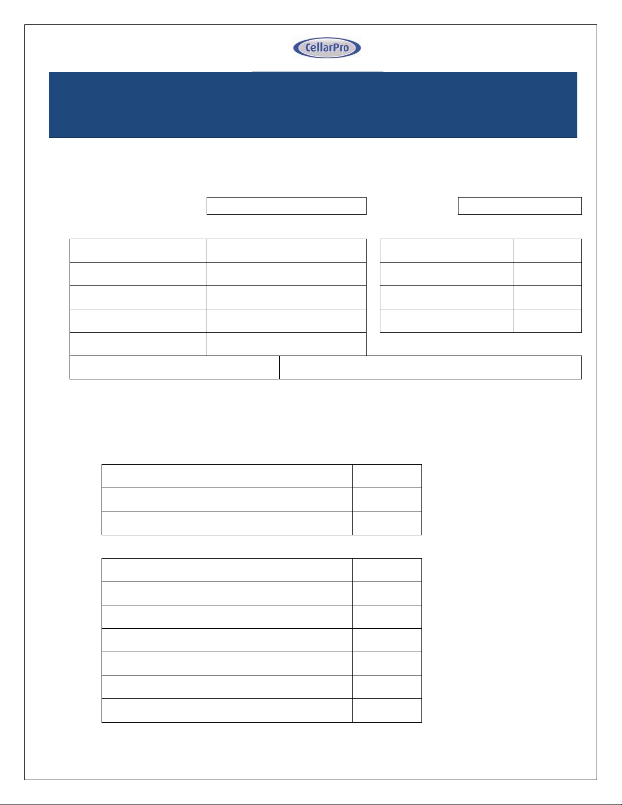
Technician Name
Tech Phone
System Information
Piping Information
Customer Name
R-134a system charge lb.
Condensing Unit Model #
Line-set length – ft.
Condensing Unit Serial #
Liquid line diameter – OD
Evaporator Model #
Suction line diameter - OD
Evaporator Serial #
Power to Condensing Unit (Check One)
___ From Evaporator ___ From External Source
Operational Data
Take the following measurements during a normal refrigeration cycle, once the cellar has pulled down to
the set-point temperature. Make sure the compressor is running when recording the data.
Evaporator
Comment
Air temperature at Evaporator coil inlet/outlet
°F/°F
8-10°F TD
Evaporator fan speed (High / Med / Low)
Evaporator power supply voltage & amps
V & A
103-127 V – check
nameplate amps
Condensing Unit
Air temperature at Condenser coil inlet & outlet
°F/°F
20-30°F TD
Condenser fan status (ON / OFF)
Suction pressure at suction service valve
PSIG
25-35 PSIG
Suction temperature at suction service valve
°F
20°F Superheat Min.
Liquid pressure at liquid service valve
PSIG
105-180 PSIG
Liquid temperature at liquid service valve
°F
10-20°F Subcooling
Condensing Unit power supply voltage & amps
V & A
103-127 V – check
nameplate amps
**IMPORTANT**
INSTALLERS MUST FILL OUT THIS SHEET AND FAX TO
707.794.8005 OR SCAN / EMAIL TO [email protected]
TO ACTIVATE THE WARRANTY.
Installing CellarPro Split Systems requires an experienced professional and adherence to industry practices which
are described in the manual. To activate the warranty, the cooling unit must be installed properly. In order for us to
assess and approve the installation, the installing technician must complete the page below. The page can be faxed
to 707.794.8005 or emailed to [email protected]. We will contact you once we receive and review this sheet.
45 V10.14
 Loading...