

Page 1
Programming
®
Cat
Electronic
Truck Engine
February 2009
Page 2

Table of Contents
Introduction ....................................................................................... 5
What’s New ........................................................................................... 6
Maximizing Fuel Economy ................................................................... 6
Understanding the Electronic Controls ............................................. 7
Factory Specifi ed Parameters and Features ................................... 9
Customer Programmable Parameters and Specifi cations ..........10
Feature Comparison by Model .........................................................11
Data Book and Optional Parameters ............................................... 14
Informational Parameters .................................................................16
ECM Identifi cation Parameters ....................................................17
Vehicle ID .......................................................................................... 18
Vehicle Speed Parameters ...........................................................19
Vehicle Speed Calibration .............................................................. 20
Vehicle Speed Calibration (J1939-Trans) ...................................... 22
Vehicle Speed Calibration (J1939-ABS) ........................................23
Vehicle Speed Limit (VSL) ...............................................................24
VSL Protection ...................................................................................29
Tachometer Calibration .................................................................... 30
Soft Vehicle Speed Limit .................................................................31
Low Speed Range Axle Ratio .......................................................33
High Speed Range Axle Ratio ....................................................... 33
Cruise Control Parameters............................................................34
Low Cruise Control Speed Set Limit ..............................................36
High Cruise Control Speed Set Limit ..............................................37
Engine Retarder Mode ...................................................................... 38
Engine Retarder Minimum VSL Type ............................................. 40
Engine Retarder Minimum Vehicle Speed .....................................41
Auto Retarder in Cruise ....................................................................42
Auto Retarder in Cruise Increment ................................................ 44
Cruise/Idle/PTO Switch Confi guration .......................................... 46
SoftCruise/Driver Cruise™ ............................................................... 47
Adaptive Cruise Control Enable ...................................................49
Idle Parameters...............................................................................50
Idle Vehicle Speed Limit .................................................................. 51
Idle RPM Limit ...................................................................................52
Idle/PTO RPM Ramp Rate ................................................................53
Idle/PTO Bump RPM .........................................................................54
Fast Idle Engine RPM #1 & #2 ......................................................... 55
Warm Up Mode Idle Speed .............................................................56
Dedicated PTO Parameters ..........................................................57
PTO Confi guration ............................................................................. 58
PTO Top Engine Limit ........................................................................ 59
PTO Engine RPM Set Speed (0 = off) .............................................60
PTO Engine RPM Set Speed A (0 = off) .......................................... 61
PTO Engine RPM Set Speed B (0 = off) ......................................... 62
PTO to Set Speed .............................................................................. 63
Maximum PTO Enable Speed .........................................................64
PTO Cab Controls RPM Limit ...........................................................65
PTO Kickout Vehicle Speed Limit ................................................... 66
Maximum PTO Vehicle Speed ....................................................... 67
Torque Limit ...................................................................................68
PTO Shutdown Time (0 = off) ........................................................... 69
PTO Shutdown Timer Maximum RPM ........................................... 70
PTO Activates Cooling Fan .............................................................. 71
PTO Low - Percent Load Threshold ................................................ 72
Contents
Page 1
Page 3

Engine Retarder Options ...............................................................73
Exhaust Brake/Warm Up Enable ..................................................... 74
Engine/Gear Parameters ...............................................................75
Lower Gears Engine RPM Limit ...................................................... 76
Lower Gears Turn Off Speed ........................................................... 76
Intermediate Gears Engine RPM Limit .......................................... 76
Intermediate Gears Turn Off Speed ...............................................76
Gear Down Protection RPM Limit .................................................. 79
Contents
Gear Down Protection Turn On Speed ..........................................79
Top Engine Limiting (TEL) ............................................................... 81
Low Idle Engine RPM ...................................................................... 82
Transmission Style .......................................................................... 83
Eaton Top 2 Override with Cruise Switch ...................................... 84
Top Gear Ratio
Top Gear Minus One Ratio
Top Gear Minus Two Ratio .............................................. 85
Gear Fast/Run Slow ........................................................................... 87
Gear Fast/Run Super Slow ............................................................... 87
AT/MT/HT Part Throttle Shift Speed ..............................................88
Governor Type ................................................................................... 89
Transmission Neutral Start Interlock ............................................ 91
Emissions Parameters ...................................................................92
ARD Programmable Regeneration Monitoring System .............. 93
ARD Fan Enable Vehicle Speed Threshold ...................................94
ARD PTO Mode Stationary RegenerationDevice Enable Status ... 95
Malfunction Indicator Lamp Confi guration .................................. 96
Data Link ARD Disable Status .........................................................97
Number of Diesel Particulate Filters ..............................................98
Diesel Particulate Filter #1 Serial Number
Diesel Particulate Filter #2 Serial Number ...................................99
ARD Fuel Nozzle Heater Confi guration ....................................... 100
Smart Idle Parameters .................................................................101
Battery Monitor and Engine Control Voltage .................................... 102
Timer Parameters .........................................................................103
Engine Emissions Certifi cation Confi g ......................................... 104
Engine Idle Shutdown System Confi g ......................................... 105
Cold Mode Idle Shutdown Timer Enable .................................... 106
Engine Idle Shutdown Timer Reset Enable ................................ 107
Idle Shutdown Timer (0 = off) .......................................................108
Idle Shutdown Timer Maximum RPM .........................................110
Allow Idle Shutdown Override .....................................................111
Idle Shutdown Ignore Neutral Switch ........................................113
Minimum Idle Shutdown Outside Temperature ......................... 114
Maximum Idle Shutdown Outside Temperature ........................ 114
A/C Switch Fan On-Time ................................................................115
Engine Retarder Delay ................................................................... 116
Engine Monitoring Parameters ..................................................117
Engine Monitoring Mode ................................................................ 118
Engine Monitoring Lamps ...........................................................121
Engine Monitoring Lamps ...............................................................122
Warning Lamp Confi g ..................................................................... 123
Coolant Level Sensor .....................................................................124
Low Coolant Level Lamp ............................................................... 125
High Coolant Temperature Lamp .................................................. 126
Low Oil Pressure Lamp .................................................................. 127
Oil Level Switch Installation Status ............................................. 129
Maintenance Parameters ...........................................................130
Page 2
Maintenance Indicator Mode ........................................................131
PM1 Interval .....................................................................................133
Engine Oil Capacity .......................................................................134
Page 4

Trip Parameters .............................................................................136
Fuel Correction Factor ....................................................................137
Change Fuel Correction Factor ........................................... 139
PM1 Reset ...............................................................................140
Fleet Trip Reset ....................................................................... 141
Customer Parameters ........................................................... 142
State Selection .......................................................................144
Vehicle Overspeed Threshold .....................................................145
Theft Deterrent System Control .....................................................146
Theft Deterrent Password .............................................................. 147
Quick Stop Rate (0 = off) ................................................................. 148
Vehicle Activity Report Parameters .......................................... 149
Minimum Idle Time (0 = off) ............................................................150
Driver Reward ...............................................................................151
Driver Reward ..................................................................................152
Driver Reward Enable .................................................................. 153
Fan Control Parameters ...............................................................154
Fan Control Type ............................................................................ 155
Fan Pulley Ratio ...............................................................................157
Fan with Engine Retarder in High Mode ..................................... 158
Number of Cooling Fan Blades ..................................................... 159
Cooling Fan Diameter ..................................................................... 160
Minimum Fan Speed .......................................................................161
Maximum Fan Speed .......................................................................162
Maximum Fan Speed Ratio Multiplier ....................................... 163
Input Selection ..............................................................................164
Exhaust Brake Switch ...................................................................... 165
Fan Override Switch ........................................................................ 166
Transmission Neutral Switch .......................................................... 167
Torque Limit Switch ..........................................................................168
Ignore Brake/Clutch Switch ............................................................169
Two Speed Axle Switch ...................................................................170
Diagnostic Enable Switch ...............................................................171
PTO On/Off Switch ............................................................................ 172
PTO Engine Shutdown Switch ........................................................ 173
PTO Engine RPM Set Speed Input A .............................................174
PTO Engine RPM Set Speed Input B .............................................175
Remote PTO Set Switch ...................................................................176
Remote PTO Resume Switch ......................................................... 177
Cruise Control On/Off Switch ......................................................... 178
Cruise Control Set Switch ..............................................................179
Cruise Control Resume Switch ...................................................... 180
Cruise Control Pause Switch ......................................................... 181
A/C High Pressure Switch .............................................................. 182
A/C Fan Request Switch ................................................................. 183
Vehicle Speed Input ........................................................................ 184
Service Brake Pedal Position Switch #1 .............................................. 185
Service Brake Pedal Position Switch #2 .............................................. 186
Starting Aid On/Off Switch ............................................................. 187
Parking Brake Switch .....................................................................188
Clutch Pedal Position Switch .........................................................189
Retarder Low/High Switch ............................................................. 190
Retarder Med/High Switch ............................................................191
Fast Idle Enable Switch ..................................................................192
ARD Regeneration Disable Switch ............................................... 193
ARD Regeneration Force Switch ..................................................194
Air Inlet Shutoff Switch ...................................................................195
Air Inlet Shutoff Threshold Reduction Switch .............................196
ARD Soft Shutdown Switch ...........................................................197
Engine Shutdown Override Switch ............................................... 198
Contents
Page 3
Page 5

Output Selection ...........................................................................199
Fast Idle Enabled Lamp ................................................................... 200
Wait to Start Lamp ........................................................................... 201
Change Oil Lamp .............................................................................. 202
Engine Retarder Maximum Setting ............................................... 203
PTO Active Output ..........................................................................205
PTO Switch On Lamp .......................................................................206
Engine Running Output ...................................................................207
Starting Aid Output .......................................................................... 208
Contents
Engine Shutdown Output ................................................................ 209
Auxiliary Brake ................................................................................. 210
Diesel Particulate Filter Lamp ........................................................211
High Exhaust System Temperature Lamp ....................................212
Aftertreatment Disabled Lamp ......................................................213
Air Inlet Shutoff Control Relay ....................................................... 214
Lockout Solenoid (Eaton Top 2 Transmission) .....................215
Shift Solenoid (Eaton Top 2 Transmission) ................................... 216
Fuel Tank Parameters ..................................................................217
Primary Fuel Tank Capacity ........................................................... 218
Secondary Fuel Tank Capacity ..................................................... 219
Customer Passwords ...................................................................220
Customer Password #1 .................................................................. 221
Customer Password #2 ................................................................ 221
Data Link Parameters ..................................................................222
Powertrain Data Link .......................................................................223
Special Parameters......................................................................224
Customer Parameter Lockout ....................................................... 225
System Settings ............................................................................226
Trip Data .........................................................................................227
Engine Totals...................................................................................... 228
Fleet Trip Totals .................................................................................229
Driver Trip Totals ............................................................................... 230
Histograms ......................................................................................... 231
Custom Data ......................................................................................232
Miscellaneous Information ........................................................233
Multi-Torque Ratings ....................................................................... 234
Multi-Torque Ratios ..........................................................................235
Triggering Snapshots ....................................................................... 236
Cat ID/ Cat Messenger .....................................................................237
Fleet Information Software .............................................................238
On-Highway Engine Design Pro ..................................................... 239
DPF Ash Service Interval .................................................................241
DPF Regeneration ............................................................................. 242
Improving Fuel Effi ciency............................................................ 243
Trip Preparation Tips ........................................................................244
Driving Tips ........................................................................................ 245
Spec’ing Caterpillar Engines ...........................................................246
Page 4
Page 6

Introduction
By the early 1980’s, it had become evident that new
engine technologies would have to be brought to bear if
Caterpillar, or any other diesel engine manufacturer, was
to prosper in the rapidly evolving market environment.
A combination of increased government regulation,
prompted by legitimate environmental concerns,
stronger competition and more demanding market
expectations dictated totally new approaches to diesel
engine design.
In order to meet these challenges, Caterpillar embarked
on an ambitious development program to create totally
new diesel engines. That program resulted in the 3176
and the 3406B PEEC. Since 1987, the use of electronics
on Caterpillar On-Highway Engines © has grown Engine
models such as the C-10, C-12, C15, C-16, and 3126E have
been introduced. Most recently, the model year 2008
electronic engine line includes the C7, C9, C13, and C15
with ACERT
Cat manufactures a wide variety of electronic engines
for applications as varied as locomotives and very large
earth movers. This booklet covers On-Highway Engines
only.
®
Technology
Introduction
Today, electronics do much more than control the
combustion process to meet ever more stringent
emission standards and customer fuel economy
expectations. They allow the engine to talk to and
coordinate with driveline components. They allow
monitoring and control of driving habits to meet business
objectives. Remote programming and monitoring ability
allows real time fl eet control from an offi ce location.
In today’s changing economic environment, a fl eet
manager must juggle economy and driver satisfaction.
Caterpillar electronically controlled engines allow a
fl eet manager to spec a driveline free from the usual
compromises and then program the engines to refl ect
desired driving habits. In addition, the Driver Reward
feature allows the manager to automatically reward
drivers who meet preset fl eet objectives.
Incorporation of the latest, most powerful ECM,
has equipped Caterpillar On-Highway Engines with
numerous electronic features. This book outlines
Caterpillar electronic features that have the ability to
change the way fl eets operate. It is now possible to
program fl eet truck engines and sit back and let the
electronics take over.
Page 5
Page 7

What’s New
Much has changed with Caterpillar’s on-highway engine
technology since the last revision of this book in May
2005. This book picks up where the May 2005 revision
left off, covering all EPA’07 emissions compliance
changes for on-highway engines.
✔ All of the electronic parameters have been modifi ed
Introduction
to refl ect programming requirements for EPA’07 onhighway engines.
✔ Informational Parameters
Maximizing Fuel Economy
There are many parameters in this book that affect
fuel economy. To aid in selecting the parameters and
features that have the greatest impact, Caterpillar has
assembled the following list.
✔ Soft Cruise - page 47
✔ Multi-Torque Ratio - page 235
✔ Gear Down Protection - page 79
✔ Driver Reward - page 152
✔ A/C Switch Fan On - page
✔ Fast Idle RPM - page 55
✔ Pulses Per Mile - page 20
✔ Fan Override Switch - page 166
✔ Fan with Engine Retarder in High Mode - page
Page 6
Page 8

Understanding the Electronic Controls
This booklet is to aid you in choosing appropriate
programmable values. Some features fall into a
“non-programmable” or “programmable only by your
authorized Cat dealer” category. While you may not
need to be concerned about programming these
parameters, we have included them in this booklet so
you can have a greater understanding of the Caterpillar
electronic system.
Cat electronic truck engines offer a wide range of
features, these include but are not limited to:
✔ Maximum Vehicle Speed Limiting
✔ Progressive Shift
✔ Engine Idle-Shutdown Timer
✔ Wide variety of Cruise Control features
✔ Engine Brake Control
✔ Dedicated PTO control features
✔ Engine Monitoring System
Introduction
✔ Engine Diagnostics w/ fault logging including
“snapshot” recording
✔ Numerous Trip Recording options
✔ J1939 Data Link
✔ ATA (J1587) Data Link
✔ Cooling fan control including A/C high pressure
Not all of these features fall into the “customer
programmable” category. Some features, like the
ATA Data Link, have to do with the way the engine
electronics are integrated into the truck and drive
train electronics. Another example is the setting for
tachometer calibration, which comes preset from the
truck factory and should not be changed. (In fact, most
features come with a preset value from the factory.)
Other features, like password protection, can only be set
by a customer.
Page 7
Page 9

In short, the programmable features fall into two basic
categories:
Factory specifi ed parameters and features
which include both;
1 – Caterpillar Standard Features
Introduction
2 –Truck Manufacturers’ (OEM) Standard
Features
Customer specifi ed parameters and specifi ca-
tions which include both;
OEM
1 – OEM Databook Features (the ones chosen
as the truck is spec’d and ordered)
2 – Optional Programmable Features (param-
eters unique to the application and normally
set after the truck is delivered)
Customer programmable features with a
icon in the
title bar can be locked for additional security. (See
Customer Parameter Lockout, page 225 for details.)
Since the introduction of the 3176B and 3406E engines
in 1993, Caterpillar has continued to add and enhance
the features available to both the Fleet Owner and the
Owner Operator. These additions and enhancements
are made by changing the software in the Personality
Module, which is in the Electronic Control Module (ECM)
on the engine. New Personality Module Software can be
installed by an authorized Caterpillar dealer. Throughout
this booklet references are made to software release
dates to defi ne when a particular feature became
available.
Page 8
Page 10

Factory Specifi ed Parameters and
Features
Each new engine will come with several features set
at factory default settings. Some of these, like the oil
sump capacity, are set at the engine factory. Others,
like the tachometer calibration, are set by the truck
manufacturer. All of these default settings fall into one
of three categories.
1 – A specifi c value required by the engine or truck
electronics for proper operation (example - oil
sump capacity, tachometer calibration)
2 – A standard value set for convenience (example -
PTO Ramp Rate is set at 50 rpm/sec)
3 – A value set at the upper limit of the possible range
to ensure that the specifi c feature does not take effect until reset by the customer (example - Vehicle
Speed Limiting is set at 127 mph)
Introduction
Page 9
Page 11

Customer Programmable Parameters and
Specifi cations
Determining Parameters and Specifi cations
On the following pages you will see a explanation of
each electronic parameter. Along with the explanations
are helpful recommendations and in some cases, split
chart examples to help in specifi cation development.
Introduction
Another aid in determining Parameters and
Specifi cations is Cat® Design Pro (See page 236).
Customer specifi ed parameters are divided into two
sections; OEM Data Book Programmable Features
are used to spec and order a truck and the Optional
Programmable Features are used to customize the
engine for your operation.
OEM
Some OEM Data Book Programmable Features
covered are: (see page 14 for complete listing)
❑ Vehicle Speed Limit (VSL)
❑ Cruise Control Parameters
❑ Engine/Gear Parameters
❑ PTO/Fast Idle Features
❑ Idle Shutdown Timer
❑ Retarder Control
❑ Tamper Resistance
❑ Password Protection
❑ Engine Monitoring System
Optional Programmable Specifi cations covered
include, but are not limited to: (see page 14 for
complete listing)
❑ Vehicle ID (required for Caterpillar fl eet manage-
ment software)
❑ Dedicated PTO Features
❑ Fuel Usage Correction Factor (ECM vs measured)
❑ Oil Capacity Adjustment for Maintenance Indicator
❑ Customer Specifi ed PM Interval for Maintenance
Indicator
❑ Programmable Low Idle RPM
Page 10
Page 12

Feature Comparison by Model
C-10
Feature
Vehicle ID
Vehicle Speed Calibration
Vehicle Speed Limit
VSL Protection
Tachometer Calibration
Soft Vehicle Speed Limit
Two-Speed Range Axle Ratio
Low Cruise Control Set Speed Limit
High Cruise Control Set Speed Limit
Engine Retarder Mode
Engine Retarder Minimum VSL Type
Engine Retarder Minimum Vehicle Speed
(excludes C7)
Auto Retarder in Cruise
Auto Retarder in Cruise Increment
Cruise/Idle/PTO Switch Confi guration
Soft Cruise Control
Adaptive Cruise Control Enable
Idle Vehicle Speed Limit
Idle rpm Limit
Idle/PTO rpm Ramp Rate
Idle/PTO rpm Bump Rate
Fast Idle Engine rpm #1
Fast Idle Engine rpm #2
Warm Up Mode Idle Speed
PTO Confi guration
PTO Top Engine Limit
PTO Engine rpm Set Speed
PTO Engine rpm Set Speed A & B
PTO to Set Speed
Maximum PTO Enable Speed
PTO Cab Controls RPM Limit
PTO Kickout Vehicle Speed Limit
Maximum PTO Vehicle Speed
Torque Limit
PTO Shutdown Timer
PTO Shutdown Timer Maximum RPM
PTO Activates Cooling Fan
PTO Low - Percent Load Threshold
Exhaust Brake/Warm Up Enable
Lower Gears Engine rpm
C-12
C-15
C-16
zzzzzz
zzzzzz
zzzzzz
zzzzzz
zzzzzz
zzzzzz
zzzzzz
zzzzzz
zzzzzz
zzzzzz
zzzz
zzzz
zzzzzz
zzzzzz
zzzzzz
zzzzzz
zzzzzz
zzzzzz
zzzzzz
zzzzzz
zzzzzz
zzzzzz
zzzzzz
zzzzzz
zzzzzz
zzzzzz
zzzzzz
zzzzzz
zzzzzz
zzzzzz
zzzzzz
3126E
EPA 2004
EPA 2004
EPA 2007
EPA 2007
Introduction
zz
zzzz
zzzz
zzzz
zz
zz
zz
Page 11
zz
zzz
Page 13

Feature Comparison by Model
Feature
Lower Gears Turn Off Speed
Intermediate Gears Engine rpm Limit
Intermediate Gears Turn Off Speed
Introduction
Gear Down Protection rpm Limit
Gear Down Protection Turn On Speed
Top Engine Limit
Low Idle Engine rpm
Top Engine Limit with Droop
(only available PM MAR03 and older)
Transmission Style
Eaton Top 2 Override with Cruise Switch
Eaton Top 2 Gear Ratios
AT/MT/HT Part Throttle Shift Speed
Governor Type (excludes C-10, C-12, C-15, C-16
PM OCT01)
Transmission Neutral Start Interlock
(GM C7 only)
ARD Programmable Regeneration Monitoring
System
ARD Fan Enable Vehicle Speed Threshold
C-10
C-12
C-15
C-16
3126E
EPA 2004
EPA 2004
EPA 2007
zzzzzz
zzzzzz
zzzzzz
zzzzzz
zzzzzz
zzzz
zzzzzz
zz
zzzzzz
zzz
zzz
zzz
zzzzzz
zz
zz
zz
EPA 2007
ARD PTO Mode Stationary Regeneration Enable
Malfunction Indicator Lamp Confi g
(Euro IV)
Data Link ARD Disable
Number of Diesel Particulate Filters
Diesel Particulate Filter #1 & #2 S/N
ARD Fuel Nozzle Cleaner Confi guration
Battery Monitor and Engine Control Voltage
Engine Emissions Certifi cation
Confi guration (2008 and newer)
Engine Idle Shutdown System
Confi guration (2008 and newer)
Cold Mode Idle Shutdown Timer Enable (2008
and newer)
Engine Idle Shutdown Timer Reset Enable (2008
and newer)
Idle Shutdown Timer
Idle Shutdown Timer Maximum RPM
Allow Idle Shutdown Override
Idle Shutdown Ignore Neutral Switch
Minimum Idle Shutdown Outside Temp
Page 12
Maximum Idle Shutdown Outside Temp
A/C Switch Fan-On Time
zz
zz
zz
zz
zz
zz
zzzzzz
zz
zz
zz
zz
zzzzzz
zzz
zzzzzz
zz
zzzzzz
zzzzzz
zzzzzz
Page 14

Feature Comparison by Model
C-10
Feature
Engine Retarder Delay
Engine Monitoring Mode
Engine Monitoring Lamps
Warning Lamp Confi g (Red Stop Lamp)
Coolant Level Sensor
Low Coolant Level Lamp
High Coolant Temperature Lamp
Coolant Temperature Derate
Low Oil Pressure Lamp
Oil Level Switch Installation Status
(GMT560 with 3126 & C9 only)
Maintenance Indicator Mode
PM1 Interval
Engine Oil Capacity
Fuel Correction Factor
Change Fuel Correction Factor
(Dash Access)
PM1 Reset (Dash Access)
Fleet Trip Reset (Dash Access)
Customer Parameters (Dash Access)
State Selection (Dash Access)
Vehicle Overspeed Threshold
Theft Deterrent
Theft Deterrent Password
Quick Stop Rate
Minimum Idle Time
Driver Reward Enable
Fan Control Type
Fan Pulley Ratio
Fan with Engine Retarder in High Mode
Number of Cooling Fan Blades
Cooling Fan Diameter
Minimum Fan Speed
Maximum Fan Speed
Maximum Fan Speed Ratio Multiplier
Primary Fuel Tank Capacity
(GMT560 with 3126 & C9 only)
Secondary Fuel Tank Capacity
(GMT560 with 3126 & C9 only)
Customer Passwords #1 & #2
C-12
C-15
C-16
zzzz
zzzzzz
zzzz
zzzzzz
zz
zzzzzz
zzzzzz
zzzzzz
zzzz
zzzz
zzzzzz
zzzz
zzzz
zzzzzz
zzzzzz
zzzzzz
zzzzzz
zzzzzz
zzzzzz
3126E
EPA 2004
EPA 2004
EPA 2007
EPA 2007
Introduction
zz
zz
zz
zzzz
zz
zzz
zz
zz
z
zz
zz
zz
zz
zz
zz
zzzz
zzz
Page 13
Page 15

Data Book and Optional Parameters
OEM Data Book
Vehicle Speed Calibration .......................................................................20
Vehicle Speed Calibration (J1939 Trans) ..............................................22
Vehicle Speed Calibration (J1939 ABS) ................................................23
Vehicle Speed Limit ..................................................................................24
Vehicle Speed Limit Protection ..............................................................29
Tachometer Calibration ............................................................................30
Two Speed Axle - Low Speed Range Axle Ratio .................................33
Introduction
Nominal Axle Ratio - High Speed Range Axle Ratio ...........................33
Low Cruise Control Speed Set Limit ......................................................36
High Cruise Control Speed Set Limit ......................................................37
Engine Retarder Mode .............................................................................38
Cruise/Idle/PTO Switch Confi guration ..................................................46
Soft Cruise Control ....................................................................................47
Adaptive Cruise Control Enable ..............................................................49
Idle Vehicle Speed Limit ..........................................................................51
Idle RPM Limit ...........................................................................................52
Warm Up Mode Idle Speed .....................................................................56
Exhaust Brake/Warm Up Enable ............................................................74
Lower Gears Engine RPM Limit ..............................................................76
Lower Gears Turn Off Speed ...................................................................76
Intermediate Gears RPM Limit ...............................................................76
Intermediate Gears Turn-Off Speed.......................................................76
Gear Down Protection RPM Limit ..........................................................79
Gear Down Protection Turn-On Speed..................................................79
Top Engine Limit ....................................................................................... 81
Low Idle Engine RPM ...............................................................................82
Eaton Top 2 Override with Cruise Switch ..............................................84
Governor Type ...........................................................................................89
Transmission Neutral Start Interlock .....................................................91
ARD Programmable Regeneration Monitoring System ......................93
ARD Fan Enable Vehicle Speed Threshold ...........................................94
Malfunction Indicator Lamp Confi guration ..........................................96
Number of Diesel Particulate Filters .....................................................98
Diesel Particulate Filter #1 Serial Number ...........................................99
Diesel Particulate Filter #2 Serial Number ...........................................99
Engine Idle Shutdown System Confi guration .....................................105
Engine Monitoring Mode .......................................................................118
Engine Monitoring Lamps ......................................................................122
Warning Lamp Confi guration ................................................................123
Coolant Level Sensor .............................................................................124
Low Coolant Level Lamp ........................................................................125
High Coolant Temperature Lamp ..........................................................126
Low Oil Pressure Lamp ..........................................................................127
Oil Level Switch Installation Status .....................................................129
Engine Oil Capacity .................................................................................134
Minimum Fan Speed ...............................................................................161
Maximum Fan Speed ..............................................................................162
Maximum Fan Speed Ratio Multiplier .................................................163
Fuel Tank Parameters .............................................................................215
Primary Fuel Tank Capacity ...................................................................218
Secondary Fuel Tank Capacity .............................................................219
Multi-Torque Ratios ................................................................................233
OEM
Page
Page 14
Page 16

Optional Page
Vehicle ID ...................................................................................................18
Soft Vehicle Speed Limit ..........................................................................31
Idle/PTO Bump RPM .................................................................................54
Engine Retarder Minimum VSL Type .....................................................40
Auto Retarder in Cruise ...........................................................................42
Auto Retarder in Cruise Increment ........................................................44
Idle/PTO RPM Ramp Rate ........................................................................53
Fast Idle RPM #1 & #2 ..............................................................................55
Dedicated PTO Parameters ..............................................................57-72
ARD PTO Mode Stationary Regeneration Enable ...............................95
Data Link ARD Disable .............................................................................97
Cold Mode Idle Shutdown Timer Enable .............................................106
Engine Idle Shutdown Timer Reset Enable .........................................107
Idle Shutdown Timer ..............................................................................108
Idle Shutdown Timer Maximum RPM ..................................................110
Allow Idle Shutdown Override ..............................................................111
Idle Shutdown Ignore Neutral Switch .................................................113
Minimum Idle Shutdown Outside Temperature .................................114
Maximum Idle Shutdown Outside Temperature ................................114
Engine Retarder Delay ...........................................................................116
Maintenance Indicator Mode ...............................................................131
PM1 Interval ............................................................................................133
Fuel Correction Factor ...........................................................................137
Change Fuel Correction Factor (dash display) ...................................139
PM1 Reset (dash display) ......................................................................140
Fleet Trip Reset (dash display) ..............................................................141
Customer Parameters (dash display) ..................................................142
State Selection (dash display) ..............................................................144
Vehicle Overspeed Threshold ...............................................................145
Theft Deterrent System Control ............................................................146
Theft Deterrent Password .....................................................................147
Quick Stop Rate .......................................................................................148
Minimum Idle Time .................................................................................150
Driver Reward Enable ............................................................................153
Fan Control Type ......................................................................................155
Fan Pulley Ratio .......................................................................................157
Fan with Engine Retarder in High Mode .............................................158
Number of Cooling Fan Blades .............................................................159
Cooling Fan Diameter .............................................................................160
Customer Passwords #1 & #2 ...............................................................221
Customer Parameter Lockout ...............................................................225
Introduction
Page 15
Page 17

Informational Parameters
Outlined below are parameters as programmed from
the Caterpillar Factory. This list serves to briefl y explain
these parameters that appear when connecting the
Caterpillar service tool to the truck engine.
Introduction
Selected Engine Rating
• Rating Number - Specifi c rating within a family
• Rating Type - Standard or Multi-Torque Rating
• Multi-Torque Ratio (C13/C15 only) - Trip point for
multi-torque selection
• ARD Confi guration Code - Identifi es the correct
Caterpillar Regeneration System Confi guration
• Advertised Power - Advertised Power at a specifi c
RPM
• Governed Speed - Maximum vehicle speed set by
the ECM
• Rated Peak Torque - Rated torque at a certain RPM
• Top Engine Speed Range - Top Engine Limit (TEL)
• Test Spec - Engine rating performance data
• Test Spec with BrakeSaver - Engine rating perfor-
mance data with a BrakeSaver (not available on
EPA’07 and newer engines)
ECM Identifi cation Parameters
• Engine Serial Number - Serial number of engine
• ECM Serial Number - Serial number of engine’s ECM
• Personality Module Part Number - Flash fi le down-
loaded in ECM
• Personality Module Release Date - Date electronics
placed it into production
• Truck Manufacturer (C7 only) - Confi gures the cor-
rect set of parameter options
• Vehicle Application Type - Emergency Vehicle or
Standard rating
Security Access Parameters
• Total Tattletale - Sum of all parameter changes
• Last Tool to change Customer Parameters - Last Cat-
erpillar service tool to change a customer parameter
• Last Tool to change System Parameters - Last Cater-
pillar service tool to change a system parameter
• ECM Wireless Communications Enable - Used to
confi gure the ECM with wireless communication
Page 16
Page 18

ECM Identifi cation Parameters
Factory Databook Optional
OEM
• Vehicle ID ............................... ✔
ECM Identifi cation Parameters
Page 17
Page 19

Vehicle ID
Description:
The Vehicle ID parameter allows the truck or fl eet owner
to electronically identify the vehicle with a unique set of
characters. The Vehicle ID can be up to 17 characters
long.
The Vehicle ID is required when using the optional Fleet
Information Software (FIS).
ECM Identifi cation Parameters
Available:
All electronically controlled on-highway engines
covered in this handbook
Range:
Range Cat Default
17 Alpha-Numeric
Characters
Advantages:
Fleet Information Software offers many unique
advantages to any fl eet that uses Cat electronic engines.
Assigning a Vehicle ID allows you to track the engine
and vehicle performance using FIS. For complete details
about Caterpillar’s Fleet Information Software contact
your local Cat dealer.
All Zeros
Disadvantages:
None
Recommendations:
✔ Caterpillar recommends using the Vehicle ID
feature for all applications where the owner or
operator expects to generate vehicle specifi c
reports.
✔ The Vehicle ID is often entered as the Vehicle
Identifi cation Number (VIN).
Page 18
Page 20

Vehicle Speed Parameters
Factory Databook Optional
OEM
• Vehicle Speed Calibration ... ✔
• Vehicle Speed Calibration
(J1939 Trans) .......................... ✔
• Vehicle Speed Calibration
(J1939 ABS) ............................ ✔
• Vehicle Speed Limit (VSL) .... ✔
• VSL Protection ....................... ✔
• Tachometer Calibration........ ✔
• Soft Vehicle Speed Limit ...... ✔
• Two Speed Axle - Low Speed
Range Axle Ratio ................... ✔
• Nominal Axle Ratio - High
Speed Range Axle Ratio ...... ✔
Vehicle Speed Parameters
Page 19
Page 21

Vehicle Speed Calibration
OEM
Description:
The value ( Pulses per Mile, PPM) of this parameter is
used by the ECM to convert the vehicle speed signal
into miles per hour (or kilometers per hour). The value is
calculated using tire revolutions per mile, rear axle ratio
and the number of teeth on the transmission chopper
wheel. This parameter is programmed by the OEM.
Vehicle Speed Parameters
PPM = M x Ra x N
Example: 31,200 = 502 x 3.90 x 16
M = Tire revolutions per mile. This information is
available from the tire manufacturer.
Ra = Rear Axle Ratio. This is typically found
on the housing of the rear axle, or on the
specifi cation sheet for the vehicle
N = Number of chopper teeth on the transmission
drive shaft where the magnetic pickup is
mounted. The value is typically 16, but may be
11.
Available:
All electronically controlled on-highway engines
Range:
Engine
3126E, C9
GM
3126E, C7, C9
OTHER
C-10, C-12,
C-15, C-16
C11, C13, C15
& All EPA07
Minimum Maximum
4000 PPM
(2485 ppkm)
4000 PPM
(2485 ppkm)
4000 PPM
(2485 ppkm)
4000 PPM
(2485 ppkm)
Range
384000 PPM
(238080 ppkm)
384000 PPM
(238080 ppkm)
150000 PPM
(93226 ppkm)
150000 PPM
(93226 ppkm)
32000 PPM
(19884 ppkm)
Programmed
14000 PPM
(8696 ppkm)
Programmed
Cat
Default
Not
Not
Advantages:
Proper calculation of the Vehicle Speed Calibration
parameter is essential for proper cruise control and
speedometer (if controlled by the ECM) operation, and
accurate Fleet and Driver Trip Data.
Disadvantages:
Miscalculation of the Vehicle Speed Calibration
parameter will cause all values calculated by the ECM
using the Vehicle Speed value to be in error (e.g. vehicle
miles, fuel economy, etc.). Precise calculation is critical
to provide accurate calculated values from the ECM.
Page 20
Page 22

Recommendations:
✔ Let the OEM calculate and program Vehicle Speed
Calibration parameter based on the truck specs.
✔ Recalculate and program the Vehicle Speed
Calibration parameter if any changes are made to
the driveline components, such as a different rear
axle ratio or a tire size change.
Vehicle Speed Parameters
Page 21
Page 23
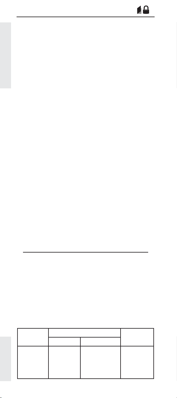
Vehicle Speed Calibration (J1939-Trans)
Description:
If a value is programmed into the Vehicle Speed
Calibration (J1939 - Trans) parameter the ECM will use
the data that is received from the transmission controller
over the J1939 data link to calculate vehicle speed.
The Vehicle Speed Cal (J1939-Trans) parameter value
represents the Transmission Output Shaft revolutions
per mile. If this parameter is not programmed, the
Vehicle Speed Parameters
ECM use one of the other vehicle speed inputs for
calculations.
When the ECM is confi gured to receive Vehicle Speed
information from an Electronic Transmission Control Unit
via the J1939 datalink, the attached transmission must
be capable of supporting the J1939 ETC1 Broadcast
Message that provides the transmission output shaft
speed.
OEM Responsibilities:
• Determine if the transmission is capable of supporting the required ETC1 message protocol.
• Determine the parameter value to be programmed
for a given chassis by one of the methods listed
below.
OEM
Parameter Calculation Methods:
Method 1
Vehicle Speed Cal (J1939-Trans) =
Transmission Output Shaft revolutions per mile
Method 2
Vehicle Speed Cal (J1939-Trans) =
Transmission Speed Sensor pulse per mile
Number of teeth on the output shaft chopper wheel
Method 3
Vehicle Speed Cal (J1939-Trans) =
Tire revolutions per mile x Axle ratio
Available:
All electronically controlled on-highway engines
covered in this handbook
Range:
Page 22
Engine
3126E, C7,
C9, C-10,
C-12,
C-15, C-16,
C11, C13, C15
Minimum Maximum
0 revs per
(0 rev per km)
mile
Range
65000 revs per
mile
(43000 revs per
km)
Cat
Default
Not
Programmed
Page 24

Vehicle Speed Calibration (J1939-ABS)
OEM
Description:
If a value is programmed into the Vehicle Speed
Calibration (J1939 - ABS) paramter the ECM will use the
data that is received from the ABS controller over the
J1939 data link to calculate vehicle speed. The Vehicle
Speed Cal (J1939-ABS) parameter value represents
the ratio of actual tire revolutions per mile divided by
assumed ABS tire revolutions per mile, and is used
with the wheel speed signal (received over the J1939
datalink) to calculate vehicle speed.
It is important to note that if this calibration method is to
be used, the ABS must be able to support the J1939 High
Resolution Wheel Speed Broadcast Message, which
provides wheel speed from the two rear wheels. In
addition to the wheel speed, the ABS will also transmit
the actual revolutions per mile, which should be divided
by the assumed ABS tire revolutions per mile to obtain
the Vehicle Speed Cal (J1939-ABS) parameter.
OEM Responsibilities:
• Determine if the ABS can support the required message protocol mentioned above.
• It is recommended that the OEM program the Vehicle Speed Calibration parameter.
Vehicle Speed Parameters
Parameter Calculation Method:
Vehicle Speed Cal =
Actual Tire Revolutions Per Mile
Assumed ABS Tire Revolutions Per Mile
Available:
All electronically controlled on-highway engines
covered in this handbook
Range:
Engine
3126E, C7, C9,
C-10, C-12,
C-15, C-16,
C11, C13, C15
Minimum Maximum
Range
0 6.550
Default
Programmed
Cat
Not
Page 23
Page 25
Vehicle Speed Limit ( VSL)
OEM
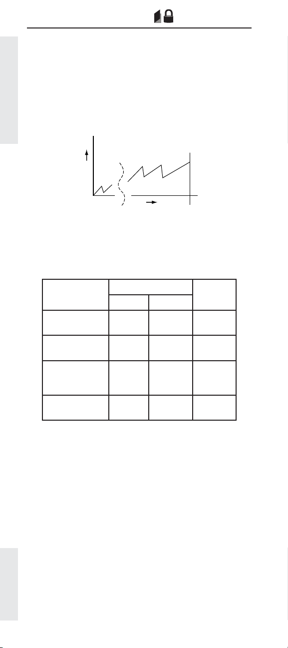
Description:
Vehicle speed limiting sets the maximum speed of the
truck. Vehicle Speed Limiting cuts off the fuel to the
injectors when the truck exceeds the programmed
speed. With the release of NOV95 Personality Module
Software, VSL can be exceeded using cruise control
if the High Cruise Control (HCC) Set Limit parameter
is programmed higher than the Vehicle Speed Limit
parameter ( ).
Vehicle Speed Parameters
See page 31
R
P
M
VSL
MPH
Available:
All electronically controlled on-highway engines
covered in this handbook. The ability to program HCC Set
Limit above VSL is available on heavy duty engines only.
Range:
Engine
3126E, C7, C9 GM
3126E, C7, C9
Other
C-10, C-12, C-15,
C-16, C11, C13,
C15
2007 C7, C9, C13,
C15
Range
Minimum Maximum
30 MPH
(48 km/h)
30 MPH
(48 km/h)
30 MPH
(48 km/h)
30 MPH
(48 km/h)
75 MPH
(121 km/h)
127 MPH
(204 km/h)
127 MPH
(204 km/h)
127 MPH
(204 km/h)
Cat
Default
75 MPH
(121 km/h)
127 MPH
(204 km/h)
127 MPH
(204 km/h)
75 MPH
(121 km/h)
Advantages:
Using the VSL feature allows you to “gear fast - run
slow” to optimize the balance between fuel economy
and performance or simply specify for the best fuel
economy. Setting VSL allows the truck operator to
consistently operate the engine and truck at fuel
effi cient and safe vehicle speeds. Without VSL, most
trucks can be capable of very high vehicle speeds, due
to GFRS/GFRSS spec’ing methods.
Disadvantages:
VSL can be a hard limit that allows no fuel until the
vehicle slows to a speed below the programmed limit.
This makes the common practice of “running at hills”
very diffi cult. Soft VSL ( ) may alleviate this
Page 24
problem if the driver expects to operate at or above VSL
See page 31
on downhill runs.
Page 26

Recommendations:
✔ Gearing for best fuel economy.
✔ The Driver Incentive feature can be used to
automatically adjust the VSL accoding to the
drivers operating habit.
Engine Note RPM MPH
3126E
C-10
C-12
C-15
C-16
C7
EPA 2004 and
newer C7
ACERT (Truck)
EPA 2004
and newer
C7 ACERT
(Specialty
Vehicles)
GCW < 50,000 lbs 2000 60
GCW= 50,000+ lbs 2200 60
Linehaul applications with
80,000 lbs or less
9,10,or 15 speed single
overdrive transmission
13 or 18 speed dual over-
drive transmission
410 hp and below 1550 65
435 hp and above 1500 65
50,000 GCW or less 2000 60
Provides more startability
or load speed performance
50,000 GCW
860 & 800 lb-ft
50,000 GCW
660 & 620 lb-ft
33,000 GCW
860 lb-ft
33,000 GCW
800 lb-ft
33,000 GCW
660 & 620 lb-ft
33,000 GCW
520 lb-ft
26,000 GCW
860 lb-ft
26,000 GCW
800 lb-ft
26,000 GCW
660 & 620 lb-ft
26,000 GCW
520 lb-ft
Fire Truck - 50,000 GCW
860 lb-ft
Coach(RV) - 34,000 GCW
(w/ tow unit)
925 & 860 lb-ft
1600 65
1550 65
1450-
1500
2200 60
2000 60
2150 60
1775 60
1850 60
2000 60
2150 60
1700 60
1775 60
1900 60
2050 60
2000 55
1750 65
Vehicle Speed Parameters
65
Page 25
Page 27

60,000 GCW or less,
C9
C11 60,000 GCW or less 1450 65
Pre-2007 C13 80,000 GCW or less 1450 65
C13 80,000 GCW or less 1400 65
Vehicle Speed Parameters
C13 MT
C15
C15 MT
C15
Heavy Haul
EPA 2004
and newer
C15 ACERT
(Heavy Haul)
less than 1250 lb-ft
60,000 GCW or less,
greater than 1250 lb-ft
80,000 GCW or less
430 hp, 1550/1750 lb-ft
60,000 GCW or less
430 hp, 1450/1650 lb-ft
80,000 lb GCW or less,
Less than 1750 lb-ft
80,000 lb GCW or less,
1750 lb-ft and above
80,000 GCW or less
435 hp, 1550/1750 lb-ft
80,000 GCW or less
475 hp, 1650/1850 lb-ft
90,000 GCW or more
80,000 - 85,000 lb GCW,
1650 lb-ft
80,000 - 85,000 lb GCW,
1750 lb-ft
80,000 - 85,000 lb GCW,
1850 - 2050 lb-ft
85,000 - 90,000 lb GCW,
1650 lb-ft
85,000 - 90,000 lb GCW,
1750 lb-ft
85,000 - 90,000 lb GCW,
1850 - 2050 lb-ft
100,000 lb GCW,
1650 lb-ft
100,000 lb GCW,
1750 lb-ft
100,000 lb GCW,
1850 - 2050 lb-ft
110,000 lb GCW,
1650 lb-ft
110,000-140,000 lb GCW,
1750 lb-ft
110,000-140,000 lb GCW,
1850 - 2050 lb-ft
140,000-200,000 lb GCW,
1850 - 2050 lb-ft
200,000-240,000 lb GCW,
1850 - 2050 lb-ft
1650 65
1550 65
1325 65
1400 65
1325 65
1325 65
1500-
1650
1450 65
1400 65
1350 65
1525 65
1475 65
1425 65
1600 65
1550 65
1500 65
1625 62
1575 62
1500 62
1575 62
1650 62
Cruise
Speed
Page 26
Page 28

EPA 2004
and newer
C13 & C15
ACERT
(Line Haul)
EPA 2004
and newer
Vocational C9
ACERT
EPA 2004 and
newer Voca-
tional C13 &
C15 ACERT
P&D
(Van, Reefer)
EPA 2004 and
newer Vo-
cational C13
& C15 ACERT
(Cement
Mixer)
EPA 2004 and
newer Voca-
tional C13 &
C15 ACERT
(Dump)
EPA 2004 and
newer Voca-
tional C13 &
C15 ACERT
(OWS)
80,000 lb GCW or less,
1450 lb-ft
80,000 lb GCW or less,
1550 lb-ft
80,000 lb GCW or less,
1650 lb-ft
80,000 lb GCW or less,
Aerodynamic,
1750/1850/2050 lb-ft
80,000 lb GCW or less,
Non-Aerodynamic,
1750/1850/2050 lb-ft
80,000 lb GCW or less,
Car Hauler,
1850 lb-ft
80,000 lb GCW or less,
Car Hauler,
2050 lb-ft
55,000 lb GCW or less,
Coach,
1450 lb-ft
60,000 lb GCW or less,
P&D (Van, Stake, etc.)
1150 lb-ft
60,000 lb GCW or less,
P&D (Van, Stake, etc.)
1250 lb-ft
70,000 lb GCW or less,
Cement Mixer/Dump
1150 lb-ft
70,000 lb GCW or less,
Cement Mixer/Dump
1250 lb-ft
80,000 lb GCW or less,
Tanker (Fluids)
1250 lb-ft
80,000 lb GCW,
1450 lb-ft
80,000 lb GCW, 1550
lb-ft
80,000 lb GCW,
1650 lb-ft
70,000 lb GCW,
1150 lb-ft
70,000 lb GCW,
1250 lb-ft
70,000 lb GCW,
1350 lb-ft
70,000 lb GCW,
1350 lb-ft
70,000 lb GCW,
1450 lb-ft
70,000 lb GCW,
1550 lb-ft
70,000 lb GCW,
1650 lb-ft
70,000 lb GCW,
1850 lb-ft
80,000 lb GCW,
Oil Well Service
1450 lb-ft
1400 58
1400 62
1400 65
1325 65
1375 65
1425 65
1325 65
1325 65
1650 65
1600 65
1600 55
1525 55
1650 60
1475 62
1475 65
1400 65
1525 55
1450 55
1550 62
1550 62
1475 62
1475 65
1400 65
1375 65
1475 62
Vehicle Speed Parameters
Page 27
Page 29

✔ If engine RPM at Vehicle Speed Limit is less than
or equal to Peak Toque RPM + 100, select another
axle ratio or transmission to increase engine RPM.
Otherwise driveability may be adversely affected.
Use Design Pro to check for gradeability at cruise
speed to ensure it is 1.0% or greater. Also, use
Design Pro to check for gradeability at peak torque
to ensure it is 1.8% (1.5% minimum).
Vehicle Speed Parameters
Page 28
Page 30

VSL Protection
OEM
Description:
This tamper-resistant feature is a programmed engine
RPM limit that the engine will not exceed if the ECM
should lose the vehicle speed signal. In other words, if
the vehicle speed signal is lost the truck will not exceed
the Vehicle Speed Limit (VSL). The VSL Protection
parameter should be set high enough that the vehicle
can limp home, but low enough that it will not be capable
of exceeding the VSL.
Note: When VSL Protection is programmed to Top
Engine Limit (TEL) rpm, diagnostic codes 84-01, Loss of
Vehicle Speed Signal and 84-10, Vehicle Speed Rate of
Change are disabled.
Available:
All electronically controlled on-highway engines
covered in this handbook
Range:
Range
Engine
C-10, C-12,
C-15, C-16,
C11, C13, C15
3126E GM 1700 RPM 1700 RPM 1700 RPM
3126E Other,
C7, C9
1000 RPM TEL RPM TEL RPM
1700 RPM TEL RPM TEL RPM
Cat DefaultMinimum Maximum
Vehicle Speed Parameters
Advantages:
The tamper resistance feature helps deter those who
may be tempted to try and circumvent the vehicle
speed signal. If the ECM were to lose the vehicle speed
signal for any reason, the engine rpm would be limited
to the programmed RPM value of the VSL Protection
parameter.
Disadvantages:
None
Recommendations:
✔ Caterpillar recommends electronic engines be
protected by setting this feature to an RPM value
equal to:
VSL Protection (rpm) =
VSL x R
x Rt x M
a
60
where;
VSL = Vehicle Speed Limit
Ra = Rear Axle Ratio
R
M = Tire revolutions per mile
= Transmission Ratio in the highest gear
t
Page 29
Page 31

Tachometer Calibration
OEM
Description:
Programmed by the OEM, this parameter is used by the
ECM to convert the engine speed signal into revolutions
per minute for a tachometer.
Available:
All electronically controlled on-highway engines
covered in this handbook
Vehicle Speed Parameters
Range:
Engine
C-10, C-12, C-15, C-16,
C11, C13, C15
3126E GM, C7, C9
GM 530/540
C7, C9
GM T560
3126 Other &
2007 C7, C9, C13, C15
Range
Minimum Maximum
12.0 PPR 500.0 PPR 113.0 PPR
2.0 PPR 500.0 PPR 17.5 PPR
2.0 PPR 500.0 PPR 2.0 PPR
2.0 PPR 500.0 PPR 134.0 PPR
Advantages:
By using the ECM Output to drive the in-dash tachometer
the need for a separate sensor for the tachometer is
eliminated.
Cat
Default
Recommendations:
✔ For most applications the factory default is correct.
✔ For ECM driven tachometer applications the in-
dash tachometer must be set to the same pulses
per revolution (PPR) setting as the ECM.
✔ To verify that the ECM is driving the tachometer,
perform the tachometer special test in Cat ET.
When running the special test, the tachometer
reading should sweep to approximately 1500 rpm.
If not, use the following calculation to correct the
Tachometer Calibration parameter value.
PPR
Tach 1500
X
=
PPR = current Tachometer Calibration value
Tach = value displayed on the tachometer during the
test
X = the desired Tachometer Calibration value
1500 = value that should be displayed on the
tachometer during the test
Page 30
Page 32
Soft Vehicle Speed Limit
Description:
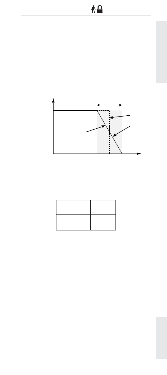
Both Vehicle Speed Limiting (VSL) and Soft Vehicle
Speed Limiting (Soft VSL) set the maximum speed of
the truck. Vehicle Speed Limiting cuts off the fuel to the
injectors when the truck exceeds the VSL programmed
mile per hour value. When you choose Soft VSL, fuel
delivery is modulated when VSL is reached. When the
truck reaches the programmed VSL value, the fuel is not
abruptly cut off. Instead, it is gradually reduced. Soft VSL
may allow the truck to exceed VSL by a maximum of 2.5
MPH (4 km/h), when the truck is using less than 50% of
the available engine horsepower.
5 MPH
100%
(8 km/h)
No
Vehicle Speed Parameters
Available
HP
Soft VSL
0
Vehicle Speed MPH (km/h)
VSL
Yes
Available:
All electronically controlled on-highway engines
covered in this handbook
Range:
Range
N o
Yes
Cat
Default
No
Advantages:
Using Soft VSL feature not only allows you to “gear
fast – run slow” to optimize a balance between fuel
economy and performance or simply specify for the best
fuel economy, but also allows the driver to “run at hills”
by “warming” the turbo at the bottom of the hill. This
means that there is enough fuel to keep moderate boost
levels even though fuel delivery is tapered off by Soft
VSL.
Page 31
Page 33

Disadvantages:
Not setting VSL allows the truck operator to “run fast”
and as a result get poor fuel economy. Also, some
drivers may not like driving with Soft VSL enabled.
Some common complaints are that there seems to be
lower power and the truck may not feel like it can hold a
constant speed. However, these effects are due to the
modulated fuel delivery, and once a driver gets used to
them, will still result in the advantages listed previously.
This perceived power loss can be even more noticeable
on trucks that are spec’ed near minimum gradeability
Vehicle Speed Parameters
requirements.
Recommendations:
✔ Do not use Soft VSL unless you expect the truck to
operate at or above VSL in uneven or fl at terrain.
Page 32
Page 34
Low Speed Range Axle Ratio
High Speed Range Axle Ratio
FORMERLY: NOMINAL AXLE RATIO - HIGH SPEED RANGE AXLE RATIO
TWO-SPEED AXLE - LOW SPEED RANGE AXLE RATIO
OEM
OEM
Description:
These two parameters must be programmed when a
Two-Speed Axle On/Off Switch is used by the ECM in
order to adjust the vehicle speed calibration. When a
two-speed axle is used, the change in gear ratios from
the high speed range to the low speed range alters the
calibration of the Vehicle Speed Limit and Vehicle Speed
Calibration, which require a calibration adjustment to
ensure the ECM-driven speedometer and ECM-stored
information correctly refl ect the actual vehicle speed.
Available:
All electronically controlled on-highway engines
covered in this handbook
Range:
Range
Minimum Maximum
Low
Engine
3126E, C7, C9 0.00 0.00 19.99 9.99 0.00
C-10, C-12,
C-15, C-16,
C11, C13, C15
EPA’07 and
newer C7, C9,
C13, C15
Speed
Range
1.00 1.00 19.99 9.99 1.00
1.00 1.00 19.99 19.99 1.00
High
Speed
Range
Low
Speed
Range
High
Speed
Range
Cat
Default
Vehicle Speed Parameters
Advantages:
Proper calculation of the Low Speed Range Axle
Ratio and High Speed Range Axle Ratio parameters is
essential for proper cruise control and speedometer (if
controlled by the ECM) operation, and accurate fl eet and
driver trip data.
Disadvantages:
None
Recommendations:
✔ Let the OEM calculate the Low Speed Range Axle
Ratio and High Speed Range Axle Ratio parameters
based on the truck specifi cations.
✔ Recalculate and program the Low Speed Range
Axle Ratio and High Speed Range Axle Ratio
parameters if any changes are made to the rear
axle ratios. Note that repairing or replacing the
rear end with the same axle ratio will not cause
a problem or require any recalculation for this
parameter.
Page 33
Page 35

Cruise Control Parameters
Factory Databook Optional
• Low Cruise Control
Speed Set Limit ..................... ✔
• High Cruise Control
Speed Set Limit ..................... ✔
• Engine Retarder Mode ......... ✔
Cruise Control Parameters
• Engine Retarder Minimum
VSL Type ................................. ✔
• Engine Retarder Minimum
Vehicle Speed ........................ ✔
• Auto Retarder In Cruise ....... ✔
• Auto Retarder In Cruise
Increment ............................... ✔
• Cruise/Idle/PTO Switch
Confi guration ......................... ✔
• Soft Cruise Control ................ ✔
• Adaptive Cruise Control ....... ✔
Description:
Cruise control allows the comfort and convenience of
automotive type cruise control, complete with “bump”
speed settings (“Bump Cruise” allows the operator
to change the vehicle speed in 1 MPH (1.6 km/h)
increments by “bumping” the Accel or Decel switch).
While in cruise mode, the ECM monitors and maintains
vehicle speed at a set value. Additionally, the use of
an engine retarder while the cruise control is “On”
has three programmable modes to match your braking
method. The retarder can also be programmed to
automatically turn on when the truck exceeds the cruise
set speed while going down hill.
OEM
Advantages:
Using cruise control can reduce driver fatigue and
improve fuel economy when used correctly. Caterpillar’s
SoftCruise speed control can provide a smoother ride
and additional fuel economy. The SoftCruise feature is
most benefi cial in rolling terrain.
Page 34
Page 36

Disadvantages:
Cruise control offers few disadvantages. If the Low
Cruise Control setting is set too low it may allow drivers
to operate the cruise in slower city traffi c which may not
be desirable. However, if Low Cruise Control is set too
high the driver will not be able to use it when climbing
long grades.
Using the standard cruise (by setting Caterpillar’s
SoftCruise speed control to “off”) can cause the driver
to sense uneven fueling - rapid fuel on/fuel off. This may
discourage the use of cruise control and negatively
effect fuel economy and driver comfort.
Recommendations:
✔ Use cruise control by setting both the High and Low
cruise control speed limits (HCC and LCC).
✔ Set the HCC at the highest speed you intend the
vehicle to cruise. This may be above the Vehicle
Speed Limit parameter setting.
✔ Do not set the cruise control limit right on top of a
shift point. Driveability may be adversely affected.
Check your settings against a split chart for your
driveline.
Incorrect Correct
Cruise Control Parameters
RPM
Do not set Cruise
Control Limits on
top of shift points
MPH
✔ To take full advantage of SoftCruise, set the High
Cruise (HCC) parameter to at least 3 mph below the
Vehicle Speed Limit Parameter (VSL).
Example: VSL = 65, HCC = 62 or less
✔ On the other hand, to encourage the use of cruise
control, set HCC to 3 mph above the recommended
VSL. This will result in the truck being operated in
cruise, with the HCC speed reached by “bumping”
up the cruise.
Page 35
Page 37

Low Cruise Control Speed Set Limit
OEM
Description:
Low Cruise Control Speed Set Limit (LCC) sets the
minimum vehicle speed for which cruise control may be
activated.
Available:
All electronically controlled on-highway engines
covered in this handbook
Cruise Control Parameters
Range:
30 MPH
(48 km/h)
15 MPH
(24 km/h)
25 MPH
(40 km/h)
15 MPH
(24 km/h)
15 MPH
(24 km/h)
15 MPH
(24 km/h)
Range
75 MPH
(121 km/h)
127 MPH
(204 km/h)
75 MPH
(121 km/h)
127 MPH
(204 km/h)
127 MPH
(204 km/h)
127 MPH
(204 km/h)
Default
30 MPH
(48 km/h)
127 MPH
(204 km/h)
25 MPH
(40 km/h)
127 MPH
(204 km/h)
127 MPH
(204 km/h)
30 MPH
(48 km/h)
Engine
Minimum Maximum
3126E GM
3126E Other
C7, C9 GM
C7, C9 Other
C-10, C-12,
C-15, C-16,
C11, C13,
C15
2007 C7, C9,
C13, C15
Cat
Note: If Adaptive Cruise Control is Enabled, the minimum for
the Low Cruise Control Speed Set Limit is 30 MPH.
Advantages:
Programming of this parameter can restrict the use of
cruise control to those places where it is proper.
Disadvantages:
If the Low Cruise Control Speed Set Limit is set too low
it may allow drivers to operate the cruise in slower city
traffi c, which may not be desirable. However, if LCC is
set too high, the driver will not be able to use it when
climbing long grades.
Recommendations:
✔ A typical value for Low Cruise Control Speed Set
Limit is 30 MPH (48 km/h).
Page 36
Page 38

High Cruise Control Speed Set Limit
OEM
Description:
High Cruise Control Speed Set Limit sets the maximum
vehicle speed for which cruise control may be used. If
the driver attempts to set a vehicle speed higher than
the programmed value of High Cruise Control Speed Set
Limit, the programmed value will become the cruise set
speed.
It is possible to program High Cruise Control Speed Set
above the programmed Vehicle Speed Limit. However,
the driver can only attain speeds higher than VSL by
using the ACCEL switch and “bumping” up the vehicle
speed.
Available:
All electronically controlled on-highway engines
covered in this handbook
Range:
Engine
3126E, C7, C9 GM
3126E, C7, C9 Other
C-10, C-12, C-15,
C-16, C11, C13, C15
2007 C7, C9, C13,
C15
Range
Minimum Maximum
30 MPH
(48 km/h)
20 MPH
(32 km/h)
30 MPH
(48 km/h)
30 MPH
(48 km/h)
75 MPH
(121 km/h)
127 MPH
(204 km/h)
127 MPH
(204 km/h)
127 MPH
(204 km/h)
Cat
Default
75 MPH
(121 km/h)
127 MPH
(204 km/h)
127 MPH
(204 km/h)
75 MPH
(121 km/h)
Cruise Control Parameters
Advantages:
Using cruise control can reduce driver fatigue and
improve fuel economy. Fleets may want to set HCC
above VSL to encourage use of cruise control.
Disadvantages:
If High Cruise Control Speed Set is programmed to a
value above the Vehicle Speed Limit (VSL) the truck
most likely will be driven at higher speeds, therefore
reducing fuel economy.
Recommendations:
✔ Set the High Cruise Control Speed Set Limit at the
highest speed you intend the vehicle to cruise.
✔ Set the High Cruise Control Speed Set Limit 3 to 5
MPH (5 to 13 km/h) below the Vehicle Speed Limit
(VSL). This allows the driver to “run at hills” in
rolling terrain and allows some reserve speed for
passing.
✔ If increased security is needed, this parameter can
be “locked” using the Customer Parameter Lockout
( ).
See page 225
Page 37
Page 39
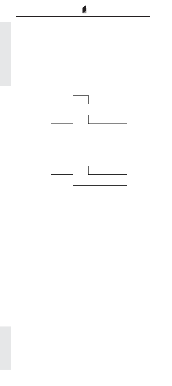
Engine Retarder Mode
OEM
Description:
When the driver is operating an engine retarder with
the cruise control switch “On” and steps on the service
brake, two customer selectable modes of operation are
available, Coast and Latch. One additional Manual mode
is available, which does not require the cruise switch to
be in the “On” position and operates like a retarder on a
mechanically governed engine.
Cruise Control Parameters
Coast Mode:
Service
Brake
Applied
Released
Engine
Retarder
On
Off
Coast Mode engages the engine retarder when the
driver presses (applies) the service brake pedal. When
the pedal is released, the retarder disengages.
Latch Mode:
Service
Brake
Engine
Retarder
Applied
Released
On
Latch Mode engages the retarder when the driver
presses (applies) the service brake. The driver can then
release the service brake and the retarder will remain
engaged until another input, such as depressing the
throttle or clutch, engine RPM drops below 800 RPM, or
the retarder is turned off, is supplied.
Manual Mode does not require the Cruise Control
Switch to be in the “On” position. In Manual Mode
the engine retarder will activate anytime the Retarder
Switch is “On”, engine RPM is above 800 RPM and the
engine is not being fueled.
Available:
All electronically controlled on-highway engines
covered in this handbook
Page 38
Page 40

Range:
Engine Range
3126E, C7,
C9, C-10,
C-12, C-15,
C-16, C11,
C13, C15
Manual
Coast
Latch
Cat
Default
Manual
Advantages:
The Coast and Latch settings of the Engine Retarder
Mode can offer increased driver comfort and reduce
driver fatigue.
Disadvantages:
None
Recommendations:
✔ This is a driver preference feature. Program to the
setting the driver prefers.
Cruise Control Parameters
Page 39
Page 41
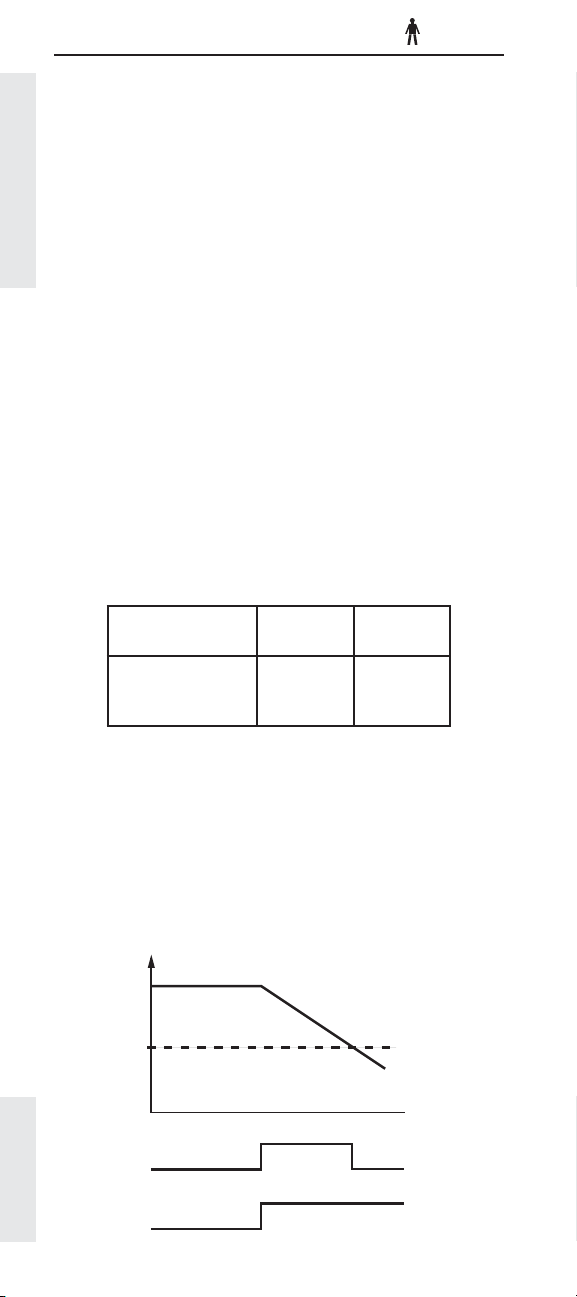
Engine Retarder Minimum VSL Type
Description:
Engine Retarder Minimum Vehicle Speed Limit Type
defi nes how the Engine Retarder Minimum Vehicle
Speed parameter will be used.
If the Engine Retarder Minimum Vehicle Speed Limit
Type is programmed to the “soft” setting, the engine
retarder will remain ON below the value programmed in
the Engine Retarder Minimum Vehicle Speed until the
Cruise Control Parameters
normal engine retarder turn-off parameters are met.
If the Engine Retarder Minimum Vehicle Speed Limit
Type is programmed to the “hard” setting, the engine
retarder will turn off when the value programmed in the
Engine Retarder Minimum Vehicle Speed is reached.
In both cases the engine retarder will remain off until
vehicle speed is higher than the programmed value of
the Engine Retarder Minimum Vehicle Speed and the
retarder has been re-engaged.
Available:
C-10, C-12, C-15, C-16, C11, C13, C15 heavy duty engines
and all 2007 On-Highway Engines
Range:
Engine Range
C-10, C-12, C-15,
C-16, C11, C13, C15,
2007 C7 & C9
Soft Limit
Hard Limit
Cat
Default
Hard Limit
Advantages:
Provides fl exibility for driver comfort while complying to
local restrictions.
Disadvantages:
None
Recommendations:
✔ This is a driver preference feature. Program to the
setting the driver prefers.
60
Vehicle
Speed
30
MPH
(km/h)
0
On
On
Page 40
Engine Retarder
(Hard Limit)
Engine Retarder
(Soft Limit)
Off
Off
Page 42

Engine Retarder Minimum Vehicle Speed
Description:
Engine Retarder Minimum Vehicle Speed is similar to
Low Cruise Control Speed Set Limit. Engine Retarder
Minimum Vehicle Speed sets the minimum vehicle speed
at which retarder operation is allowed. This parameter
affects both the Engine Retarder Solenoids and any
auxiliary brake. Setting the Engine Retarder Minimum
Vehicle Speed to 0 (Zero) disables this feature.
Available:
C-10, C-12, C-15, C-16, C11, C13, C15 heavy duty engines
and EPA’07 C9 On-Highway Engines
Range:
Engine
C-10, C-12, C-15,
C-16, C11, C13, C15
& EPA’07 C9
Range
Minimum Maximum
0 MPH
(0 km/h)
127 MPH
(204 km/h)
Cat
Default
0 MPH
(0 km/h)
Advantages:
The Engine Retarder Minimum Vehicle Speed
parameter turns the engine retarder off, at or below the
programmed speed. This parameter can also be used
to prevent excessive use of the engine retarder at low
speeds.
Cruise Control Parameters
Disadvantages:
If the engine retarder is engaged and the truck slows
to the value of the Engine Retarder Minimum Vehicle
Speed the retarder will turn off.
Recommendations:
✔ Be sure to observe all federal, state, and local
ordinances regarding the use of the engine retarder
when setting the Engine Retarder Minimum Vehicle
Speed parameter.
Page 41
Page 43
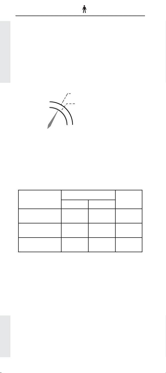
Auto Retarder in Cruise
Description:
Auto Retarder in Cruise determines the miles per hour
(km/h) value above the cruise set speed that the engine
retarder will turn On. The Retarder switch must be in
the On position and cruise control set, for this feature
to operate. Programming the Auto Retarder in Cruise
parameter to 0 (zero) will disable the feature. This
parameter works in conjunction with the Auto Retarder
Cruise Control Parameters
in Cruise Increment parameter. The initial braking level
(Low or Hi) of retarding is dependent on the value of the
Auto Retarder in Cruise Increment parameter.
45
Example: The cruise speed is set at 55 MPH and Auto
Retarder in Cruise parameter is programmed to 3 MPH.
When the truck accelerates to 58 MPH, by going down
hill, the retarder will activate.
Available:
All electronically programmed on-highway engines
Cruise Set Speed
Auto Retarder In Cruise
Programmed to 3 MPH
55
65
Range:
Range
Engine
C-10, C-12, C-15,
C-16, C11, C13, C15
C7, C9
EPA’07 C7, C9, C13,
C15
0 MPH
(0 km/h)
3 MPH
(5 km/h)
0 MPH
(0 km/h)
10 MPH
(16 km/h)
10 MPH
(16 km/h)
10 MPH
(16 km/h)
Advantages:
Auto Retarder in Cruise can increase driver comfort and
reduce driver fatigue while maintaining the desired road
speed.
Note: The maximum Retarder level is determined by the
Retarder Level switch position.
Disadvantages:
Programming this parameter to a speed that is too
low can result in a degraded fuel economy. See
Recommendations and the Auto Retarder in Cruise
Increment parameter discussion to avoid this effect.
Page 42
Cat
DefaultMinimum Maximum
0 MPH
(0 km/h)
0 MPH
(0 km/h)
0 MPH
(0 km/h)
Page 44

Recommendations:
✔ If Auto Retarder in Cruise is desired, program
the parameter to 3 – 5 MPH (5 – 8 km/h) to take
advantage of SoftCruise. The minimum setting with
Soft Cruise is 3 MPH due to the fact that Soft Cruise
requires 2.5 MPH to work correctly.
Cruise Control Parameters
Page 43
Page 45
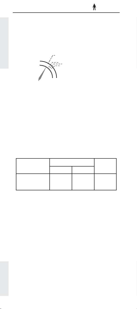
Auto Retarder in Cruise Increment
Description:
The Auto Retarder in Cruise Increment parameter
works in conjunction with the Auto Retarder in
Cruise parameter and controls the retarder level. It
requires that Auto Retarder in Cruise parameter to be
programmed to a value other than 0 (Zero).
Cruise Control Parameters
Example: The cruise speed is set to 55 MPH and Auto
Retarder in Cruise parameter is programmed to 3 MPH
and Auto Retarder in Cruise Increment is programmed to
2 MPH. When the truck accelerates to 58 MPH, by going
down hill, the Low retarder level will activate. If the truck
continues to accelerate, Medium level retarding would
activate at 60 MPH. High level of retarding will activate if
the truck reaches 62 MPH.
Available:
All electronically controlled on-highway engines
covered in this handbook
Auto Retarder In Cruise Programmed to 3 MPH
45
55
65
Cruise Set Speed
Low 58 MPH
Medium 60 MPH
High 62 MPH
Auto Retarder In Cruise Increment
Programmed to 2 MPH
Range:
Engine
C-10, C-12, C-15,
C-16, C11, C13, C15,
2007 C7 & C9
Range
Minimum Maximum
0 MPH
(0 km/h)
5 MPH
(8 km/h)
Default
(3 km/h)
Advantages:
Auto Retarder in Cruise Increment allows the driver to
customize the Auto Retarder in Cruise feature to match
his/her driving style.
The Auto Retarder in Cruise feature provides drivers
who are “graded” for incentive purposes, an automatic
method to control the amount of time above VSL.
Disadvantages:
Programming the Auto Retarder in Cruise Increment
parameter too tightly can result in a degraded fuel
economy. For instance, if it is set to zero, and the Auto
Retarder in Cruise parameter is set to 1 MPH, then all six
cylinders will retard when the vehicle exceeds cruising
speed by just 1 MPH. This can result in less desirable
fuel economy.
Page 44
Cat
2 MPH
Page 46

Recommendations:
✔ Program the Auto Retarder in Cruise Increment to
2 MPH. This will allow for all three levels of braking
to be used for smoother decel on moderate grades
✔ If High level of retarding is required, program the
Auto Retarder in Cruise Increment to 0 (Zero). If
this is done, Soft Cruise Control should not be used
(see page 47 for details on Soft Cruise Control),
since it requires 2.5 MPH to work properly.
✔ Set the Auto Retarder in Cruise Increment
parameter to the preference of the driver, bearing
in mind the potentially negative affect on fuel
economy if the increment is set too tightly.
Cruise Control Parameters
Page 45
Page 47

Cruise/Idle/PTO Switch Confi guration
Description:
Generally there are two accepted combinations of
cruise control switches. The specifi c combination of
switches is a driver convenience feature.
Available:
All electronically controlled on-highway engines
covered in this handbook
Cruise Control Parameters
Range:
Engine Range Cat Default
3126E, C7 &
C9 Other, C-10,
C-12, C-15,
C-16, C11, C13,
C15, 2007 C7
& C9
3126E, C7, C9
GM
Advantages:
The switch setting can be changed to meet driver
preferences.
Set/Accel-Resume/
Decel
Set/Decel-Rsume/
Accel
Set/Accel-Resume/
Set/Decel-Rsume/
Decel
Accel
OEM
Disadvantages:
None
Recommendations:
✔ This feature should be changed based on driver
preference.
Page 46
Page 48
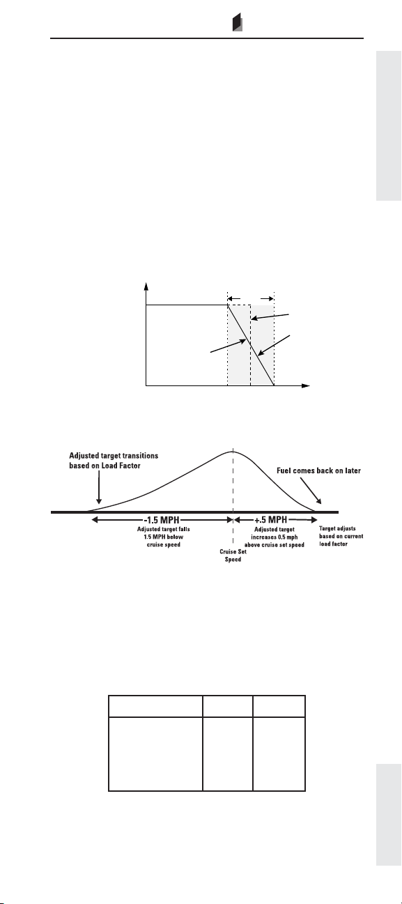
SoftCruise/ Driver Cruise™
OEM
Description:
The Caterpillar SoftCruise speed control feature
provides a small “soft” window centered around the
cruise set speed. With SoftCruise “On”, the ECM will
modulate fuel delivery for a more effi cient, smoother
cruise control. SoftCruise reduces the abrupt on/off fuel
cycling that is common with some diesel engine cruise
controls. It allows the truck to increase speed slightly
above the cruise set speed while going down hill (noload) to “warm up” the turbocharger. This provides quick
boost and improved engine response on the next hill.
Driver Cruise enhances SoftCuise by having the cruise
respond slightly quicker, for improved driveability while
maximizing fuel economy.
5 MPH
100%
Available
HP (kW)
SoftCruise
0
Vehicle Speed MPH (km/h)
SoftCruise
(8 km/h)
Cruise Control
Set Speed
No
Yes
Cruise Control Parameters
Driver Cruise
Available:
All electronically controlled on-highway engines
covered in this handbook. Driver Cruise is only available
of EPA’04 and EPA’07 Heavy Duty Engines.
Range:
Engine Range Default
3126E, C7, C9,
C-10, C-12, C-15,
C-16, C11, C13,
C15
Y e s
No
Yes
Page 47
Page 49

Advantages:
SoftCruise and Driver Cruise speed control can provide
a smoother ride and improved fuel economy. These
features are most benefi cial in rolling terrain.
Disadvantages:
Like Soft VSL, SoftCruise Control may allow the vehicle
speed to fall 2.5 mph below the VSL before full fuel is
demanded by the governor. This can lead to a perceived
(not an actual) loss of power.
Cruise Control Parameters
Recommendations:
✔ Set to customer’s preference.
Page 48
Page 50

Adaptive Cruise Control Enable
OEM
Description:
Adaptive Cruise Control allows the interaction of the
VORAD on board radar system to interact with the
cruise control settings. The VORAD system will adjust
the cruise control “set” speed to help maintain vehicle
following distances.
Available:
EPA’04 C11, C13, C15, EPA’07 C7, C9, C13 & C15
Range:
Engine Range Cat Default
EPA’04 C7, C9, C11
C13, C15
EPA’07 C7, C9,
C13, C15
Enabled
Disabled
Disabled
Advantages:
System integration for optimal performance of VORAD
system.
Disadvantages:
None
Recommendations:
✔ If VORAD is installed, enable feature.
Cruise Control Parameters
Page 49
Page 51

Idle Parameters
FORMERLY - OLD PTO
Factory Databook Optional
• Idle Vehicle Speed Limit ...... ✔
• Idle RPM Limit ....................... ✔
Idle Parameters
• Idle/PTO RPM Ramp Rate .... ✔
• Idle/PTO Bump RPM ............. ✔
• Fast Idle RPM #1 & #2 .......... ✔
• Warm Up Mode Idle Speed . ✔
PTO GOVERNOR PARAMETERS
OEM
Page 50
Page 52

Idle Vehicle Speed Limit
FORMERLY - IDLE/PTO VEHICLE SPEED LIMIT OR
PTO/EXTENDED IDLE VEHICLE SPEED LIMIT OR
PTO MODE VEHICLE SPEED LIMIT
OEM
Description:
Idle Vehicle Speed Limit is the maximum vehicle speed
allowed when the engine is in the Idle Mode. (Idle Mode
is entered if the engine RPM is set by the cruise control
Set/Resume switch, when the cruise control On/Off
switch is in the On position.) If the value programmed in
the Idle Vehicle Speed Limit parameter is exceeded, the
set engine rpm will not be maintained.
Available:
All electronically controlled on-highway engines
covered in this handbook
Range:
Transmission
Style
Manual
Automatic
Range
Minimum Maximum
1 MPH
(2 km/h)
1 MPH
(2 km/h)
15 MPH
(24 km/h)
5 MPH
(8 km/h)
Cat
Default
1 MPH
(2 km/h)
1 MPH
(2 km/h)
Idle Parameters
Advantages:
None
Disadvantages:
None
Recommendations:
✔ For non-PTO operations where overnight idling is
the primary usage of this feature, set the Idle/PTO
Vehicle Speed Limit to 2 MPH.
✔ For PTO Operation use the Dedicated PTO feature
and related parameters ( )
see page 57
Page 51
Page 53

Idle RPM Limit
FORMERLY - PTO/EXTENDED IDLE ENGINE RPM LIMIT OR
PTO MODE ENGINE RPM LIMIT
OEM
Description:
Idle RPM Limit is the maximum engine rpm in the idle
mode. Idle mode occurs if the engine rpm is set using the
cruise control On/Off switch and the Set/Resume switch.
The actual upper limit of this parameter is determined
Idle Parameters
by the programmed Top Engine Limit. The lower limit is
determined by the programmed Low Idle Engine rpm.
Available:
All electronically controlled on-highway engines
covered in this handbook
Range:
Engine
3126E, C7,
C9
C-10, C-12,
C-15, C-16,
C11, C13,
C15
Range
Minimum Maximum
700 RPM TEL RPM TEL RPM
600 RPM TEL RPM TEL RPM
Cat
Default
Advantages:
Being able to electronically control engine rpm offers
more precise control than a hand throttle. The ability to
limit maximum engine rpm in the Idle mode saves fuel
and prevents unnecessary engine wear.
Disadvantages:
None
Recommendations:
✔ For non-PTO operations where overnight idling is
the primary usage of this feature, set the Idle/PTO
RPM Limit between 900 and 1100 rpm based on
climatic conditions.
Page 52
Page 54
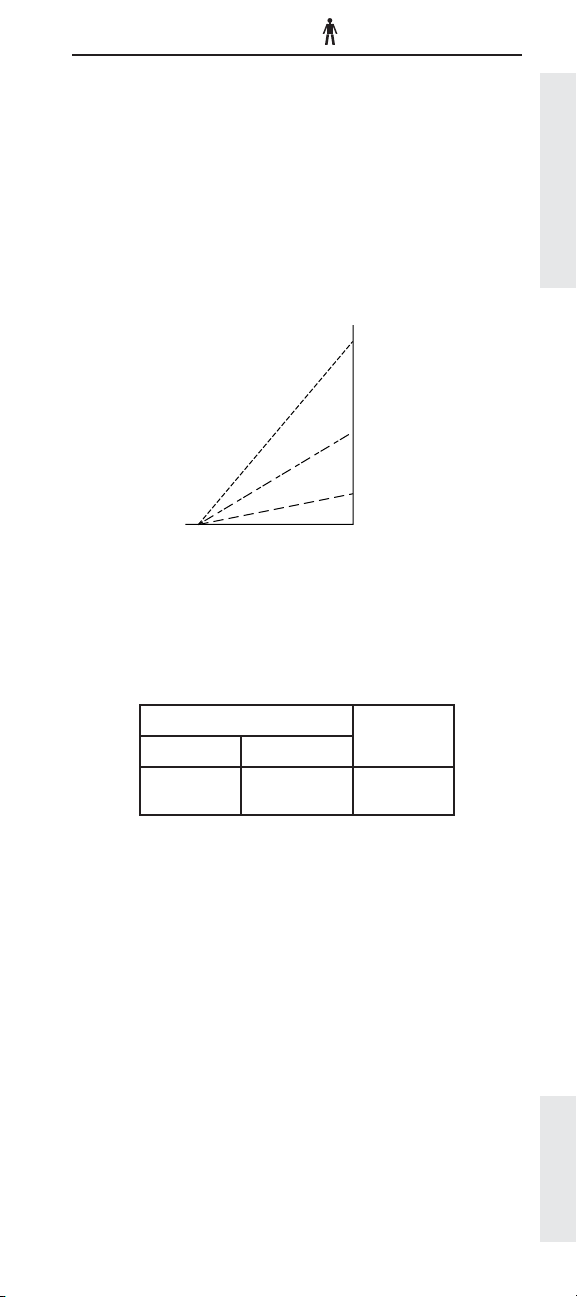
Idle/PTO RPM Ramp Rate
FORMERLY - PTO ENGINE RPM RAMP RATE
Description:
The Idle/PTO Ramp Rate parameter defi nes how many
rpm the engine will change in one second when in
Idle Mode or Dedicated PTO Mode. This parameter
determines Accel, Decel and Resume Idle or PTO
Engine rpm rates of increase/decrease. Notice that the
parameter applies to both idle control (rpm set using
cruise control On/Off and Set/Resume switches) and
PTO control (rpm set using PTO On/Off and Set/Resume
switches)
1000
R
P
500
M
50
01
Time (Second)
Available:
All electronically controlled on-highway engines
covered in this handbook
Range:
Range
Minimum Maximum
Cat
Default
Idle Parameters
5 RPM/sec 1000 RPM/sec 50 RPM/sec
Advantages:
Setting the Idle/PTO Ramp Rate can help reduce work
cycle time by reducing the time it takes to get the engine
up to the preferred RPM.
Disadvantages:
Setting an Idle/PTO Ramp Rate too high could accelerate
the failure of some PTO attachments.
Recommendations:
✔ This programmable feature is application
dependent and should be programmed based on
customer specifi c requirements.
Page 53
Page 55

Idle/PTO Bump RPM
Description:
The Idle/PTO RPM Bump determines the rpm increment/
decrement when the Accel/Decel switches are briefl y
“bumped”. It applies to both Dedicated PTO and Idle
modes of operation.
Available:
Idle Parameters
All electronically controlled engines covered in this
handbook
Range:
Range
Minimum Maximum
5 RPM 500 RPM 20 RPM
Advantages:
Setting the Idle/PTO RPM Bump can help reduce work
cycle time by reducing the time it takes to get the engine
up to the preferred RPM.
Disadvantages:
None
Cat
Default
Recommendations:
✔ This programmable feature is application
dependent and should be programmed based on
customer specifi c requirements.
Page 54
Page 56

Fast Idle Engine RPM #1 & #2
Description:
With the installation of a momentary contact Fast Idle
switch, the driver can toggle the switch and the engine
will go immediately to a preset RPM value.
The available RPM values are stored as the Fast Idle
Engine RPM #1 or Fast Idle Engine RPM #2 parameters.
The ranges for these two parameters are listed below.
The engine will increase from the programmed Low Idle
to the Fast Idle Engine RPM #1 value when the Fast Idle
switch is fi rst pressed and released. The second time
the Fast Idle switch is pressed and released, the engine
will increase to the Fast Idle Engine RPM #2 value. After
pressing the Fast Idle switch a third time, the engine will
return to low idle, and Fast Idle will be disabled.
The difference between the Fast Idle Engine RPM #1
and #2 parameters is that the #1 parameter can be
overridden by the operator, whereas the #2 parameter
cannot be overridden beyond the programmed value.
To override the Fast Idle Engine RPM #1 parameter, the
operator should press the accelerator pedal until the
desired rpm is reached, and then depress the Fast Idle
Enable switch. This rpm will then be the Fast Idle Engine
RPM #1 value as long as the ECM is powered.
Idle Parameters
Available:
Pre EPA’07: 3126E, C7, and C9 medium duty engines
EPA’07: All On-Highway Engine Platforms
Range:
Engine
3126E, C7,
C9
2007 C13,
C15
Fast Idle
Engine
RPM #
1 700 RPM TEL RPM 1000 RPM
2 700 RPM TEL RPM 0 RPM
1 600 RPM TEL RPM 1000 RPM
2 600 RPM TEL RPM 0 RPM
Range
Minimum Maximum
Cat
Default
Advantages:
Setting the Fast Idle Engine RPM can help reduce work
cycle time by reducing the time it takes to get the engine
up to the preferred RPM.
Recommendations:
✔ This programmable feature is application
dependent and should be programmed based on
customer specifi c requirements.
Page 55
Page 57

Warm Up Mode Idle Speed
OEM
Description:
The Warm Up Mode Idle Speed parameter determines
engine speed while the engine is in the warm up mode.
The Warm Up Mode Idle Speed parameter will be
activated when the sum of coolant temperature and
intake manifold air temperature is less than 86° F (30° C).
Idle Parameters
While the engine is in the warm up mode, the engine will
return to low idle if either the service brake or the clutch
pedal is depressed, an automatic transmission is put in
gear, or the ECM detects vehicle speed. After returning
to low idle, the engine can then return to Warm Up Mode
Idle Speed if the sum of coolant temperature and intake
manifold temperature 86° F (30° C) as mentioned above.
Note:
Heavy duty warm up speed is non-programmable and is
fi xed at 1000 rpm.
Available:
Pre EPA’07: Medium duty on-highway engines.
EPA’07: All On-Highway Engine Platforms
Range:
Range
Engine
DefaultMinimum Maximum
Cat
3126E, C7, C9 700 rpm 1400 rpm 1000 rpm
2007 C7 & C9 700 rpm 1400 rpm 0 rpm (off)
2007 C13 & C15 600 rpm 1400 rpm 0 rpm (off)
Advantages:
This parameter allows the driver a fl exible rpm range
for the Warm Up Mode Idle Speed depending upon the
specifi c application.
Disadvantages:
None
Page 56
Page 58

Dedicated PTO Parameters
The Dedicated PTO Parameters require JAN95 or newer
Personality Module Software, therefore Dedicated
PTO Parameters apply to all engine models covered
in this handbook. For further detail on the latest PTO
Installation and Setup refer to the PTO Application and
Installation guide RENR1282. Contact your authorized
Caterpillar dealer to order this publication.
Anytime the Dedicated PTO circuit is Active, both the
length of time and the fuel used will be stored in the Trip
Data Information in the ECM (See the Trip Data Section
on page ).
227
Factory Databook Optional
OEM
• PTO Confi guration ................. ✔
• PTO Top Engine Limit ............ ✔
• PTO Engine RPM Set Speed ✔
• PTO Engine RPM Set Speed A ✔
• PTO Engine RPM Set Speed B ✔
• PTO to Set Speed .................. ✔
• Maximum PTO Enable Speed ✔
• PTO Cab Throttle RPM Limit ✔
• PTO Kickout
Vehicle Speed Limit .............. ✔
• Maximum PTO Vehicle Speed ✔
• Torque Limit ............................ ✔
• PTO Shutdown Time ............. ✔
• PTO Shutdown Timer
Maximum RPM ...................... ✔
• PTO Activates Cooling Fan .. ✔
• PTO Low-Percent Load
Threshold ............................... ✔
Dedicated PTO Parameters
Page 57
Page 59
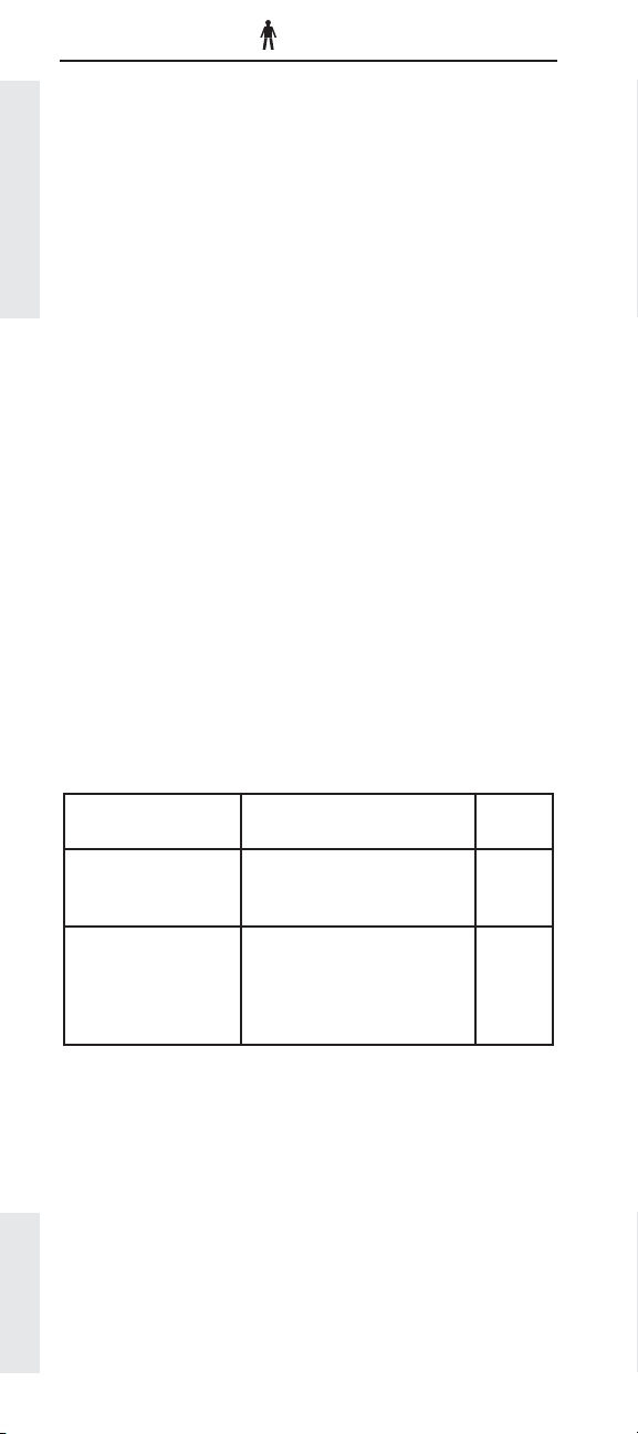
PTO Confi guration
Description:
The PTO Confi guration parameter defi nes the features
that are available for dedicated PTO applications
and the input signals that the ECM monitors while in
PTO mode. The PTO Confi guration parameter has the
following programmable options:
Dedicated PTO Parameters
dedicated PTO
Cab Switches - indicates that the Cruise Control
Set/Resume Switch, in the cab, is being used
for control of Dedicated PTO function .
Remote Switches - indicates that control of the
Dedicated PTO function is outside the cab.
Remote Throttle - indicates that a Remote
Throttle is being used as part of the Dedicated
PTO operation.
Remote Throttle & J1939 Speed Command - indi-
cates that a Remote Throttle is being used as
part of the Dedicated PTO operation in addition
to the ECM monitoring the J1939 TSC1 Speed
Command.
Available:
All electronically controlled on-highway engines
covered in this handbook
Range:
Engine Range
OFF - indicates the application does not use
Pre EPA’07
EPA’07 and newer C7,
C9, C13 & C15
Cab Switches,
Remote Switches,
Remote Throttle
Cab Switches,
Remote Switches,
Remote Throttle,
Remote Throttle & J1939
Speed Command
Cat
Default
Off
Off
Advantages:
The PTO Confi guration parameter allows the engine
to be easily customized to the many PTO application,
and reduces the number of mechanical components
required.
Recommendations:
✔ For the most recent information on PTO installation
and setup, refer to the PTO Application and Installation Guide RENR1282.
Page 58
✔ If Dedicated PTO is used, all Dedicated PTO param-
eters must be programmed for proper operation.
Page 60

PTO Top Engine Limit
Description:
If the engine has been wired to work in the dedicated
PTO mode, the PTO Top Engine Limit parameter can be
programmed to a value up to the maximum rpm of the
engine. This parameter is only in effect when the engine
is in the Dedicated PTO mode, Pre EPA 2004.
Note: PTO Confi guration must be programmed to Cab
Switches, Remote Switches, Remote Throttle, or Remote
Throttle & J1939 Speed Command before this parameter
can be programmed.
Available:
All electronically controlled on-highway engines
covered in this handbook
Range:
Engine
C-10, C-12,
C-15, C-16,
C11, C13,
C15
3126E, C7,
C9
Range
Minimum Maximum
600 RPM TEL RPM TEL RPM
700 RPM TEL RPM TEL RPM
Cat
Default
Dedicated PTO Parameters
Advantages:
PTO Top Engine Limit allows the fl exibility to work in PTO
applications where additional RPM above the engine
Top Engine Limit RPM is required, or where RPM must
be limited to prevent damage to the PTO device.
Disadvantages:
None
Recommendations:
✔ Refer to RENR1282 for specifi c details.
Page 59
Page 61

PTO Engine RPM Set Speed (0 = off)
Description:
PTO Engine RPM Set Speed is the engine RPM the
engine will proceed to when the PTO On/Off circuit is
On and the Cruise/PTO Set switch is toggled. If the PTO
to Set Speed parameter (see page 63) is programmed to
Yes, the engine will go to the PTO Engine RPM Set Speed
whenever the PTO On/Off circuit is On.
Dedicated PTO Parameters
Note: PTO Confi guration must be programmed to Cab
Switches or Remote Switches before this parameter
can be programmed. This feature is not available for
the Remote Throttle, or Remote Throttle & J1939 Speed
Command confi gurations.
Available:
All electronically controlled on-highway engines
covered in this handbook
Range:
Range
Minimum Maximum
Low Idle
RPM
PTO TEL 0 RPM
Cat
Default
Advantages:
Allows the fl exibility to go to a specifi c engine rpm every
time when in Dedicated PTO operation.
Disadvantages:
None
Recommendations:
✔ Refer to RENR1282 for further details.
Page 60
Page 62

PTO Engine RPM Set Speed A (0 = off)
Description:
PTO Engine RPM Set Speed A is the engine RPM the
ECM will control the engine to when PTO is enabled and
the PTO Engine RPM Set Speed Input A switch is ON.
While operating at this set speed, all other speed control
inputs are ignored (Cab and Remote Throttle, and the
Set/Accel and Resume/Decel switches). This feature
will override PTO Set Speed and PTO Engine RPM Set
Speed B. The engine will operate at this programmed
speed, unless a condition is present to kickout PTO
operation (brake or clutch pedal depressed, PTO Kickout
Vehicle Speed Limit exceeded, etc.). In the event that
the PTO operation is kicked out, the engine will return to
low idle.
Note: The PTO Confi guration parameter must be
programmed to Cab Switches, Remote Switches,
Remote Throttle or Remote Throttle & J1939 Speed
Command and the PTO Engine RPM Set Speed Input A
parameter must be programmed to a hard wired switch
input, or a J1939 source for this feature to function.
Available:
EPA’07 and newer C7, C9, C13 & C15 on-highway engines
Range:
Range
Minimum Maximum
Low Idle
RPM
PTO TEL 0 RPM
Cat
Default
Dedicated PTO Parameters
Advantages:
Allows the fl exibility to choose from multiple preset
engine speeds while in Dedicated PTO mode.
Disadvantages:
None
Recommendations:
✔ Refer to RENR1282 for further details.
Page 61
Page 63
PTO Engine RPM Set Speed B (0 = off)
Description:
PTO Engine RPM Set Speed B is the engine RPM the
ECM will control the engine to when the PTO On/Off is
enabled, the PTO Engine RPM Set Speed Input B switch
is ON and the PTO Engine RPM Set Speed A switch is
OFF. While operating at this set speed, all other speed
control inputs are ignored (Cab and Remote Throttle, and
the Set/Accel and Resume/Decel switches) except PTO
Dedicated PTO Parameters
Engine RPM Set Speed A. This feature will override a
PTO Set Speed and throttle position.
Note: The PTO Confi guration parameter must be
programmed to Cab Switches, Remote Switches,
Remote Throttle or Remote Throttle & J1939 Speed
Command and the PTO Engine RPM Set Speed Input B
parameter must be programmed to a hard wired switch
input for this feature to function.
Available:
EPA’04 and newer C7, C9, C13 & C15 on-highway engines
Range:
Range
Minimum Maximum
Low Idle
RPM
PTO TEL 0 RPM
Cat
Default
Advantages:
Allows the fl exibility to choose from multiple preset
engine speeds while in Dedicated PTO mode.
Disadvantages:
None
Recommendations:
✔ Refer to RENR1282 for further details.
Page 62
Page 64

PTO to Set Speed
Description:
When the PTO to Set Speed parameter is programmed
to Yes, the engine rpm will go directly to the value
programmed in the PTO Engine RPM Set Speed
parameter (see page ) when Dedicated PTO is On. PTO
6 0
Confi guration must be programmed to Cab Switches
or Remote Switches before this parameter can be
programmed.
Note: This parameter is not available if PTO
Confi guration is programmed to Remote Throttle or
Remote Throttle & J1939 Speed Command.
Available:
All electronically controlled on-highway engines
covered in this handbook.
Range:
Range Cat Default
No
Yes
No
Advantages:
By automatically going to a programmed engine RPM
every time Dedicated PTO is engaged, cycle time can be
reduced and precise control of engine rpm is possible
for specialized PTO applications.
Dedicated PTO Parameters
Disadvantages:
None
Recommendations:
✔ Set the PTO to Set Speed Parameter to YES if the
application requires the engine to go to a specifi ed
RPM every time the Dedicated PTO feature is On.
✔ For further details, refer to RENR1282.
Page 63
Page 65

Maximum PTO Enable Speed
Description:
Maximum PTO Enable Speed sets the maximum engine
speed at which the PTO mode will engage. PTO mode
will engage when the engine RPM is at or below the
programmed value.
Available:
All EPA’07 electronically controlled on-highway engines
Dedicated PTO Parameters
covered in this handbook
Range:
Engine
EPA’04 and
newer C7, C9
EPA’04 and
newer C13, C15
Advantages:
Serves to protect PTO attachments from damage from
high speed operation.
Disadvantages:
None
Range
Minimum Maximum
700 RPM TEL RPM TEL RPM
600 RPM TEL RPM TEL RPM
Default
Cat
Recommendations:
✔ For further details, refer to RENR1282.
✔ Set to PTO attachment maximum RPM or lower.
Page 64
Page 66

PTO Cab Controls RPM Limit
(ALSO KNOWS AS “ PTO CAB THROTTLE RPM LIMIT”)
Description:
The PTO Cab Controls RPM Limit determines the engine
RPM limit of the Cab Accelerator Pedal Position Sensor
and Cab Set/Resume Switch when PTO Confi guration
is programmed to Cab Switches and the PTO On/Off
circuit is ON. This parameter is intended to prevent the
engine from overspeeding the PTO system while using
dedicated PTO.
• If Programmed to
Sensor is ignored.
• If programmed to TEL, the engine will operate to the
programmed Top Engine Limit.
• If Programmed to PTO TEL, the engine will operate
to the programmed PTO Top Engine Limit.
Note: PTO Confi guration must be programmed to Cab
Switches for this parameter to take effect. If PTO
Confi guration is programmed to Remote Switches,
Remote Throttle or Remote Throttle & J1939 Speed
Command the ECM will always ignore the Cab Controls
when PTO mode is active.
Available:
All electronically controlled on-highway engines
covered in this handbook
Low Idle, the Cab Throttle Position
Dedicated PTO Parameters
Range:
Range Cat Default
Low Idle
TEL
PTO TEL
TEL
Advantages:
Prevents the use of the cab throttle to override PTO
settings and overspeeding the PTO device.
Disadvantages:
None
Recommendations:
✔ Refer to RENR1282 for more specifi c details.
Page 65
Page 67

PTO Kickout Vehicle Speed Limit
Description:
Similar in operation to Vehicle Speed Limit, but it only
applies when the engine is in Dedicated PTO Mode. PTO
mode is entered if the PTO On/Off circuit is On. If the PTO
Vehicle Speed limit is exceeded, the engine will “kick
out” of the Dedicated PTO mode and no longer maintain
the set engine rpm.
Dedicated PTO Parameters
Available:
All electronically controlled on-highway engines
covered in this handbook
*Note: For model year 2001 HD engines this parameter
was referred to as “PTO Vehicle Speed Limit”, the name
was changed for HD engines afterwards.
Range:
Range
Minimum Maximum
1 MPH
(2 km/h)
127 MPH
(204 km/h)
Advantages:
Some Dedicated PTO applications use transmission
driven PTO’s. In some cases the vehicle is required to
travel at speeds in excess of the 15 MPH limit. That was
not possible with the combined Idle/PTO Vehicle Speed
Limit parameter. The customer now has the fl exibility
to limit vehicle speed in both Idle and Dedicated PTO
operation.
Cat
Default
1 MPH
(2 km/h)
Disadvantages:
None
Recommendations:
✔ Refer to RENR1282 for more specifi c details
Page 66
Page 68

Maximum PTO Vehicle Speed
Description:
This parameters limits fuel to maintain a maximum
vehicle speed while in PTO mode.
Note: This feature is lockable on pre-EPA’07 software
only.
Available:
All EPA’07 electronically controlled on-highway engines
covered in this handbook
Range:
Engine
EPA’07 and
newer C7, C9,
C13 & C15
* Actual Maximum is based on engine rating
15 mph (24
Range
Minimum Maximum
km/h)
127 mph (204
km/h)
Cat
Default
127 mph
(204 km/h)
Advantages:
Allows PTO accessory to operate at effi cient, maximum
speed.
Disadvantages:
None
Dedicated PTO Parameters
Recommendations:
✔ For this feature to function properly, PTO Kickout
Vehicle Speed Limit should not be set lower than
Maximum PTO Vehicle Speed.
✔ Refer to RENR1282 for additional information.
Page 67
Page 69
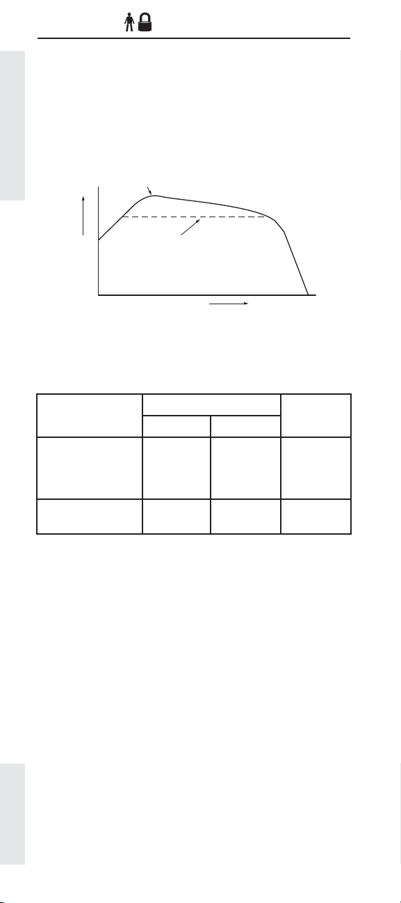
Torque Limit
Description:
The Torque Limit parameter defi nes the maximum
torque output of the engine during Dedicated PTO
operation. The maximum value is the Rated Torque of
the engine. If the Torque Limit is Programmed to a value
higher than the rated torque of the engine, the torque
limit is ignored.
Torque
Engine Torque Curve
Programmed Engine
Torque Limit
Engine Speed (RPM)
Dedicated PTO Parameters
Available:
All electronically controlled on-highway engines
covered in this handbook
Range:
200 lb ft
(270 Nm)
100 lb ft
(135 Nm)
Range
2500 lb ft *
(3400 Nm)
2000 lb ft *
(2700 Nm)
Engine
C-10, C-12, C-15,
C-16, C11, C13, C15,
EPA’07 and newer
C7 & C9
3126E, C7, C9
* Actual Maximum is based on engine rating
Minimum Maximum
Advantages:
By programming a Torque Limit the ECM can help
prevent damage to engine driven PTO devices due to
over-torque from the engine.
Cat
Default
2500 lb ft
(3400 Nm)
2000 lb ft
(2700 Nm)
Disadvantages:
None
Recommendations:
✔ Refer to RENR1282 for additional information.
Page 68
Page 70

PTO Shutdown Time (0 = off)
Description:
PTO Shutdown Time is the time (in minutes) the engine
will operate in PTO mode before shutting down. The
timer will only count with no vehicle speed and the PTO
On/Off circuit ON. The PTO Shutdown Timer will not
begin counting if the engine is in Cold Mode.
This parameter is not available unless the PTO
Confi guration parameter is programmed to Cab
Switches, Remote Switches, Remote Throttle, or Remote
Throttle & J1939 Speed Command.
Note: This feature does not shut down vehicle power.
The ECM and vehicle will remain powered.
Available:
All electronically controlled on-highway engines
covered in this handbook
Range:
Range
Minimum Maximum
3 Minutes
1440
Minutes
Cat
Default
0 Minutes
Dedicated PTO Parameters
Advantages:
The PTO Shutdown Timer can limit unnecessary PTO
time, save fuel and reduce engine wear.
Disadvantages:
When the engine shuts down as a result of the PTO
Shutdown Timer the truck’s dash remains “hot”. To avoid
draining the batteries the ignition key must be switched
to the “off” position after the engine shuts down.
Recommendations:
✔ For additional information, refer to RENR1282.
Page 69
Page 71
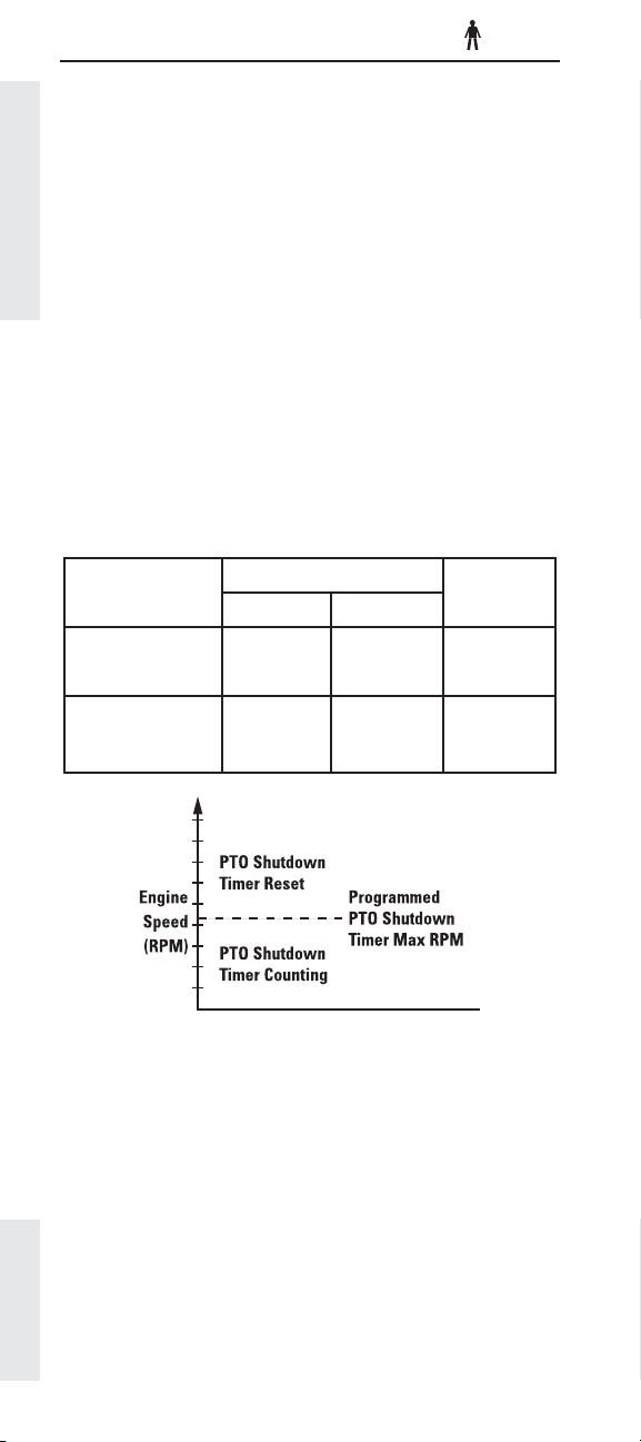
PTO Shutdown Timer Maximum RPM
Description:
PTO Shutdown Timer Maximum RPM can be used
to reset the PTO Shutdown Timer. Programming this
parameter to maximum RPM disables this feature and
will not allow the PTO Shutdown Timer to be overridden
by increasing engine RPM. If programmed to a value
below maximum RPM, the timer will be reset whenever
engine RPM exceeds this programmed value.
Dedicated PTO Parameters
Note: The PTO Confi guration must be programmed to
Cab Switches, Remote Switches, Remote Throttle, or
Remote Throttle & J1939 Speed Command before this
parameter can be programmed.
Available:
All heavy-duty on-highway engines covered in this
handbook
Range:
Engine
Minimum Maximum
Range
Cat
Default
EPA’07 and newer
C7 & C9
EPA’07 and newer
C13 & C15, all other
engines
700 rpm 2640 rpm 2640 rpm
600 rpm 2120 rpm 2120 rpm
Advantages:
Allows increased fl exibility to user.
Disadvantages:
None
Recommendations:
✔ Program to the RPM value required for the
application.
Page 70
Page 72

PTO Activates Cooling Fan
Description:
If the ECM is being used to run the engine cooling fan
circuit, this parameter can be programmed to have
the cooling fan cycle normally (based on Coolant
Temperature or Inlet Air Temperature or A/C High
Pressure) or run continuously when in the Dedicated
PTO Mode.
Note: The PTO Confi guration must be programmed to
Cab Switches, Remote Switches, Remote Throttle or
Remote Throttle & J1939 Speed Command before this
parameter can be programmed. The Fan Control Type
must also be programmed to On-Off or Three Speed Fan.
Available:
All electronically controlled on-highway engines
covered in this handbook
Range:
Range Cat Default
Normal
Continuous
Normal
Advantages:
Some applications require the fan to be on continuously
during PTO operation. This can be accomplished without
additional wiring by programming this parameter.
Dedicated PTO Parameters
Disadvantages:
If the application does not require continuous fan
operation but the ECM is programmed to Continuous
mode, excessive fuel may be consumed, increasing
overall cost of operation.
Recommendations:
✔ Refer to RENR1282 for additional information.
Page 71
Page 73
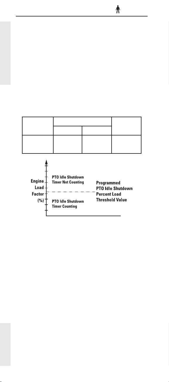
PTO Low - Percent Load Threshold
Description:
This parameter is used to determine when the PTO
Idle Shutdown Timer will function based on engine
load factor. When engine load is greater than the
programmed threshold value the PTO Idle Shutdown
Timer is temporarily disabled. The PTO Idle Shutdown
Timer will resume operation once the engine load is
below the programmed value.
Engine Retarder Options
Available:
All 2007 electronically controlled on-highway engines
covered in this handbook
Range:
Engine
Minimum Maximum
Range
Cat
Default
2007 C7, C9,
C13 & C15
0 % 100 % 100 %
Advantages:
Allows increased fl exibility to user.
Disadvantages:
None
Recommendations:
✔ Program to the percent load factor value required
for the application.
Page 72
Page 74

Engine Retarder Options
Factory Databook Optional
OEM
• Exhaust Brake/Warm
Up Enable ............................... ✔
Dedicated PTO Parameters
Page 73
Page 75

Exhaust Brake/Warm Up Enable
ALSO KNOWN AS “ EXHAUST BRAKE CONFIGURATION”
OEM
Description:
The Exhaust Brake Confi guration parameter determines
the functionality of the exhaust brake. This parameter
can be programmed to one of the following options:
None, Warm Up Device Only, Exhaust Brake Only, or
Exhaust Brake & Warm Up Device.
Engine Retarder Options
The exhaust brake can be used to apply a parasitic
load to the engine in order to aid engine warm up to
achieve normal operating temperature quicker. To
use this feature, the Exhaust Brake Confi guration
parameter must be set to either Warm Up Device Only
or Exhaust Brake and Warm Up Device. Also, the Warm
Up Mode Idle Speed parameter must be programmed
to an engine speed between 700 rpm and 1400 rpm. If
these preceding conditions are met, then the engine
will ramp up to the programmed Warm Up Mode Idle
Speed parameter value when the intake air temperature
is below 50 degrees Fahrenheit and the coolant
temperature is below 160 degrees Fahrenheit.
Available:
3126E, C7, and C9 medium duty engines
Range:
Engine Range Cat Default
3126E, 2007
C7 & C9,
C7 &C9 Other
C7, C9
(PM MAR04
and after)
GMT560
Warm Up Only
Exhaust Brake Only
Exhaust Brake & Warm Up
Warm Up Only
Exhaust Brake Only
Exhaust Brake & Warm Up
Exhaust Brake Only
Advantages:
This parameter allows an operator to use the installed
exhaust brake on his/her vehicle to act as an exhaust
brake, a warm up device to help the engine achieve
operating temperature quicker, or a combination of the
two. This allows fl exibility in the use of the exhaust
brake depending upon the specifi c application.
Disadvantages:
None
Page 74
None
Page 76

Engine/Gear Parameters
FORMERLY - PROGRESSIVE SHIFT PARAMETERS
Factory Databook Optional
• Lower Gears Engine
RPM Limit ............................... ✔
• Lower Gears Turn Off Speed ✔
• Intermediate Gears Engine
RPM Limit ............................... ✔
• Intermediate Gears Turn Off
Speed ...................................... ✔
• Gear Down Protection RPM
Limit ......................................... ✔
• Gear Down Protection
Turn On Speed ....................... ✔
• Top Engine Limit .................... ✔
• Low Idle Engine RPM ........... ✔
• Transmission Style ................ ✔
• Eaton Top 2 Override
with Cruise Switch ................ ✔
• Eaton Top 2 Gear Ratios ....... ✔
• Gear Fast/Run Slow .............. ✔
• Gear Fast/Run Super Slow .. ✔
• AT/MT/HT Part Throttle
Shift Speed ............................. ✔
• Governor Type ....................... ✔
• Transmission Neutral Start
Interlock ................................. ✔
OEM
Engine/Gear Parameters
Page 75
Page 77

Lower Gears Engine RPM Limit
FORMERLY - LOW GEARS #1 ENGINE RPM LIMIT
Lower Gears Turn Off Speed
FORMERLY - LOW GEARS #1 TURN OFF SPEED
Intermediate Gears Engine RPM Limit
FORMERLY - LOW GEARS #2 ENGINE RPM LIMIT
Intermediate Gears Turn Off Speed
FORMERLY - LOW GEARS #2 TURN OFF SPEED
Engine/Gear Parameters
Description:
OEM
OEM
OEM
OEM
Lower Gears Engine RPM Limit and Intermediate Gears
Engine RPM Limit are meant to approximate ideal
progressive shifting. Lower Gear Engine RPM Limiting
should be used in conjunction with Intermediate Gears
Engine RPM Limiting. However, you can choose to use
only Lower Gears Engine RPM Limit if that is best suited
to your operation.
Both Lower and Intermediate Gears RPM Limiting have
“soft” rpm limits. This means if you are in a heavily
loaded condition or starting on an especially steep grade
and do not want to shift until the engine reaches higher
rpm, the limit will not stop you. If not heavily loaded, it
simply slows the acceleration rate of the engine when
you pass the programmed setting, prompting the driver
to shift for the most “normal” operations.
The maximum engine acceleration rate above the Lower
Gears Engine RPM Limit is 33 rpm/sec and 25 rpm/sec
for Intermediate Gears Engine RPM Limiting.
The engine can accelerate all the way to your
programmed Top Engine limit (TEL) when necessary
and will not be noticed by most drivers if properly
programmed to fi t your application.
Once the Lower Gears Engine RPM Limit has been
determined, the Lower Gears Turn Off Speed is selected.
It is the speed at which the Lower Gears Engine RPM
Limit no longer applies but the Intermediate Gears
Engine RPM Limit does. It is selected as the mean
vehicle speed between where the Lower Gears Engine
RPM Limit intersects the line of gear to be limited and
the line of the next highest gear. Next, Intermediate
Gear Engine RPM Limit and Intermediate Gears Turn Off
Speed are selected in much the same way. The values
for all four parameters are automatically calculated
when using Cat
®
Design Pro.
Available:
All electronically controlled on-highway engines
covered in this handbook
Page 76
Page 78

Range:
Lower Gears Engine RPM Limit
Engine
C-10, C-12, C-15, C-16,
C11, C13, C15
3126E, C7, C9 1500 RPM TEL TEL
EPA’07 and newer
C7, C9, C13, C15
Range
Minimum Maximum
1100 RPM TEL TEL
1100 RPM TEL TEL
Lower Gears Turn Off Speed
Engine
C-10, C-12, C-15, C-16,
C11, C13, C15
3126E, C7, C9
EPA’07 and newer C7,
C9, C13, C15
Range
Minimum Maximum
3 MPH
(5 km/h)
1 MPH
(2 km/h)
1 MPH
(2 km/h)
30 MPH
(48 km/h)
15 MPH
(24 km/h)
15 MPH
(24 km/h)
Intermediate Gears Engine RPM Limit
Engine
C-10, C-12, C-15,
C-16, C11, C13, C15
Range
Minimum Maximum
1100 RPM TEL TEL
Cat
Default
Cat
Default
3 MPH
(5 km/h)
1 MPH
(2 km/h)
1 MPH
(2 km/h)
Cat
Default
Engine/Gear Parameters
3126E, C7, C9 1500 RPM TEL TEL
EPA’07 and newer C7,
C9, C13, C15
1100 RPM TEL TEL
Intermediate Gears Turn Off Speed
Engine
C-10, C-12, C-15,
C-16, C11, C13, C15
3126E, C7, C9
EPA’07 and newer C7,
C9, C13, C15
Range
Minimum Maximum
5 MPH
(8 km/h)
10 MPH
(16 km/h)
5 MPH
(8 km/h)
50 MPH
(80 km/h)
50 MPH
(80 km/h)
50 MPH
(80 km/h)
Cat
Default
5 MPH
(8 km/h)
10 MPH
(16 km/h)
5 MPH
(8 km/h)
Advantages:
Lower Gears Engine RPM Limiting and Intermediate
Gears Engine RPM Limiting improve fuel economy by
promoting progressive shifting. Needlessly “winding
up” the engine to higher RPMs before up shifting wastes
both fuel and time while failing to take advantage of
Caterpillar’s exceptional low rpm torque.
Page 77
Page 79

Disadvantages:
This setting provides minimal fuel savings for long
haul operations unless the driver stops frequently and
regularly tries to “wind it up”.
Recommendations:
✔ Each of these parameters should be left at the
factory default value when using an Automatic
Transmission, with the exception of Eaton Top 2.
Lower Gears Limit
Engine/Gear Parameters
✔ Set the Lower Gears Limit no lower than Peak
Torque rpm + 200 rpm. Properly setting this
parameter requires a close look at many factors,
including engine rating, terrain and application.
For example, heavy-duty engines are typically set
at the following:
1200 rpm + 200 rpm = 1400 rpm
Note how Lower Gears and Intermediate Gears setting
fi t in the total spec, especially in respect to Top Engine
Limiting (stair step effect).
2000
PTO
VSL
1800
1600
Lower
RPM
Gears
1400
1200
1000
0 10203040506070
LCC
Intermediate
Gears
TEL
MPH
Gear Down
Speed
Gear Down RPM
Peak
Torque
HCC
A similar graph would apply to mid-range engines.
Intermediate Gears Limit
✔ Set the Intermediate Gears Limit halfway between
the Lower Gears RPM Limit and Top Engine Limit.
For example, the C-15 is typically set to the
following:
Lower Gears Limit = 1400 rpm
Top Engine Limit = 2120 rpm
Intermediate Gears Limit = 1760 rpm
Lower Gears and Intermediate Gears Limits
✔ Use Cat® Design Pro program to determine the
most effective setting for your application.
VSL
Note: Turn Off Speeds are automatically calculated in
Page 78
the Cat® Design Pro computer program. Cat® Design
Pro is the easiest tool to use to build an effective spec.
Page 80
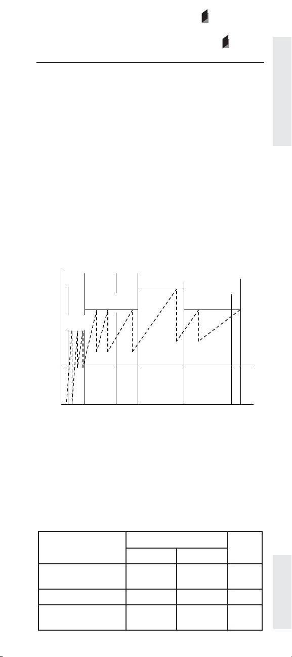
Gear Down Protection RPM Limit
FORMERLY - HIGH GEARS ENGINE RPM LIMIT
Gear Down Protection Turn On Speed
FORMERLY - HIGH GEARS TURN ON SPEED
OEM
OEM
Description:
Gear Down Protection allows you to set an engine rpm
limit for the higher gears that ensures cruising speed
can only be reached in top gear.
Gear Down Protection has two parameters to specify.
The fi rst is the Gear Down Protection Turn On Speed.
This is the point, in either mph or km/h, where the RPM
limit fi rst takes effect. In the illustration below the Gear
Down Protection Turn On Speed is set at 45 MPH. The
second parameter is the Gear Down Protection RPM
Limit. It is set at 1600 rpm in the illustration.
With some driveline combinations cruising speed can
only be reached while in the transmission’s top gear; the
Gear Down Protection RPM Limit would not have to be
set for these trucks
2000
1800
1600
RPM
1400
PTO
VSL
Lower
Gears
LCC
Intermediate
Gears
TEL
VSL
HCC
Engine/Gear Parameters
1200
1000
0 10203040506070
MPH
Peak
Torque
It is important to note that although Low/Intermediate
Gears parameters are “soft” limits, Gear Down
Protection is actually a “hard” limit.
Available:
All electronically controlled on-highway engines
covered in this handbook
Range:
Gear Down Protection RPM Limit
Engine
C-10, C-12, C-15, C-16,
C11, C13, C15
3126E, C7, C9 1700 RPM TEL TEL
EPA’07 and newer C7,
C9, C13, C15
Minimum Maximum
1300 RPM TEL TEL
1300 RPM TEL TEL
Range
Cat
Default
Page 79
Page 81

Gear Down Protection Turn On Speed
Range
Engine
3126E, C7, C9 (Other)
C-10, C-12, C-15, C-16,
C11, C13, C15
3126E, C7, C9 (GM)
Engine/Gear Parameters
EPA’07 and newer
C7, C9, C13, C15
30 MPH
(48 km/h)
30 MPH
(48 km/h)
30 MPH
(48 km/h)
127 MPH
(204 km/h)
75 MPH
(121 km/h)
127 MPH
(204 km/h)
Advantages:
Gear Down Protection helps ensure that the truck is run
in the correct (highest possible) gear at cruising speed.
Properly setting these parameters will keep the engine
in the most fuel effi cient rpm range to achieve the best
fuel economy at cruising speed.
Disadvantages (possible):
Some driveline combination can allow a driver to reach
cruising speed in more than one gear even with this
feature properly set. However, gear down protection is
still moderately effective in these situations and should
be used.
Cat
DefaultMinimum Maximum
127 MPH
(204 km/h)
75 MPH
(121 km/h)
75 MPH
(121 km/h)
If the Gear Down Protection RPM Limit is set too low,
the driver may have to wait too long to downshift when
climbing steep grades with heavy loads. This may cause
the driver to drop two transmission gears, when one
would have been adequate.
Recommendations:
✔ Set the Gear Down Protection RPM Limit such that
highway cruising speeds can only be reached in
top gear (Use Cat® Design Pro).
✔ Set Gear Down Protection RPM Limit high enough
that engine rpm does not drop below peak torque
plus 100 rpm during upshift.
✔ Set the Gear Down Protection Turn On Speed well
below the cruise speed. As with all electronic shift
strategies, do not set “gear-on” speeds on top of
shift points.
Page 80
Page 82

Top Engine Limiting ( TEL)
OEM
Description:
Top Engine Limit (TEL) sets the maximum engine rpm
value (The 3116 HEUI, 3126B and 3126 HEUI are not
programmable).
Note: This programmable feature is only available on
1998 and older engines.
Note: Lockable on Pre-EPA’07 Software Only
Available:
1998 and older C-10, C-12, 3176B and 3406E truck
engines.
Range:
Range
Engine
C-10, C-12, 3176B and
3406E
3116 HEUI
(Except 275 hp [205
kW])
3116 HEUI
(275 hp [ 205 kW])
3126 HEUI N/A N/A 2640 rpm N/A
3126B Basic N/A N/A 2640 rpm N/A
3126B Full Feature N/A N/A 2640 rpm* N/A
* Select rating of the 3126B will have a different Top Engine Limit
1600 rpm 2120 rpm Varies by
N/A N/A 2725 rpm N/A
N/A N/A 2640 rpm N/A
Cat
Default IncrementMinimum Maximum
1 rpm
Rating
Engine/Gear Parameters
Advantage:
Lower maximum engine rpm limts can save fuel. Some
applications, including automatic transmissions, require
1900+ rpm, This feature allows the fl exibility to program
an operating range to meet your specifi c need.
Disadvantages:
Most applications can be effectively accomplished
without taking an engine above 1800 rpm under power.
An engine which has a higher programmed TEL can
potentially use more fuel.
Recommendations:
✔ Caterpillar recommends programming TEL to
1820 rpm unless an automatic transmission requires
1800 - 2100 rpm for proper operatio. All other
settings should be application specifi c and
programmed on a case-by-case basis from
1600 - 2120 rpm.
✔ High performance operators and heavy haulers
should set TEL toward the maximum
Page 81
Page 83

Low Idle Engine RPM
OEM
Description:
The programmable Low Idle Engine RPM feature
sets the minimum engine speed according to driver
preferences.
Available:
All electronically controlled on-highway engines
covered in this handbook
Engine/Gear Parameters
Range:
Engine
C-10, C-12, C-15,
C-16, C11, C13, C15
3126E, C7, C9 700 RPM 800 RPM 700 RPM
Range
Minimum Maximum
600 RPM 750 RPM 600 RPM
Default
Advantages:
The ability to specify the low idle rpm can be very helpful
if a different low idle rpm is needed, either to suit unique
operating conditions or if there is resonant vibration at
a specifi c rpm ( mirrors, rattles, etc. ). Lower idle rpm in
conjunction with the proper load starting technique (“no
throttle” starts) also reduces clutch wear.
Cat
Disadvantages:
Idling at higher speed increases fuel consumption and
engine wear. Every effort should be made to stay as low
as possible.
Recommendations:
✔ This adjustment is rarely required and should be
done on a case by case basis.
Page 82
Page 84

Transmission Style
Description:
This parameter allows the ECM to work with automatic
transmissions that require additional inputs to the ECM.
Available:
All electronically controlled on-highway engines
covered in this handbook
Range:
Engine Range
C-10, C-12, C-15,
C-16, C11, C13,
C15
3126E, C7, C9
(GM)
3126E C7, C9
(Other)
EPA’07 and
newer C7 & C9
EPA’07 and
newer C13, C15
Automatic Option 1,
Automatic Option 2,
Automatic Option 3,
Automatic Option 4,
Automatic Option 1,
Automatic Option 2,
Automatic Option 3,
Automatic Option 4,
AT/MT/HT Option 1,
AT/MT/HT Option 2,
AT/MT/HT Option 3,
AT/MT/HT Option 4,
Automatic Option 1,
Automatic Option 2, Automatic Option 3, Automatic
Option 4, AT/MT/HT Option
1, AT/MT/HT Option 2, AT/
MT/HT Option 3, AT/MT/HT
Manual
Eaton Top 2
Manual Option 1,
Manual Option 2
Manual
Option 4
Manual
Automatic
Manual
Automatic
Eaton Top 2
Cat
Default
Manual
(PM OCT01 and
older)
Manual Option 1
(PM JAN02 and
newer)
Manual Option 2
(GMT560)
Universal
(GM530/540)
Manual Option 1
Manual
Manual
Engine/Gear Parameters
Advantages:
This parameter allows the engine and transmission to
work together for proper operation.
Disadvantages:
None
Recommendations:
✔ This parameter will be programmed by the truck
manufacturer and should not be changed unless
the type of transmission is changed.
Page 83
Page 85

Eaton Top 2 Override with Cruise Switch
Description:
The Eaton Top 2 Override with Cruise Switch parameter
is programmed as either Yes or No. When programmed
to Yes, this parameter disables the top 2 mode when
the cruise switch is OFF and the transmission is not yet
in the top 2 gears. When the cruise switch is in the ON
position, the top 2 mode is enabled. If the cruise switch
is in the OFF position while in one of the top 2 gears, the
Engine/Gear Parameters
ECM will go into a hold mode where the transmission
will not be shifted from the currently selected gear.
Available:
C-10, C-12, C-15, C-16, C11, C13, C15 heavy duty engines
Range:
Engine Range Cat Default
OEM
C-10, C-12, C-15, C-16, C11,
C13, C15
Note: This feature is unavailable when the Transmission Style
parameter is not programmed to Eaton Top 2.
Yes
No
No
Advantages:
The Eaton Top 2 Override with Cruise Switch parameter
gives the operator more control over the transmission
shifting in vehicles which are equipped with Eaton Top 2
transmissions.
Disadvantages:
Extra consideration should be made when cresting a
hill to avoid the top 2 feature from downshifting prior to
cresting a hill. See recommendations below for further
details.
Recommendations:
✔ The hold mode mentioned above is typically used
when cresting the top of a hill. Good driving habits
suggest lugging the engine back up to 200 rpm
below peak torque in the current gear if cresting a
hill is possible within a short period of time.
In order to do this, the operator must override the
automatic top 2 shifting to hold the transmission
in top gear. If not, the top 2 feature will perform a
downshift prior to cresting the top of the hill.
Page 84
Page 86

Top Gear Ratio
Top Gear Minus One Ratio
Top Gear Minus Two Ratio
Description:
The Top Gear Ratio parameter refers to the Eaton Top 2
Gear Ratios that are used by the ECM to decide when
to energize the Shift and Lockout solenoid outputs
(required for the Eaton Top 2 feature) when shifting
between the top two gears in vehicles equipped with
Eaton Top 2 transmissions. These parameters are Top
Gear Ratio, Top Gear Minus One Ratio, and Top Gear
Minus Two Ratio. These parameters have no effect if
the Transmission Style parameter is not programmed
to Eaton Top 2, however they must be correctly
programmed if it is programmed to Eaton Top 2.
Top Gear Ratio
This ratio identifi es the highest gear ratio for an Eaton
Top 2 Transmission. The programmable range is shown
in the table below. Note that for Gear Fast Run Slow
(GFRS) ratings the default value should be 0.731.
Top Gear Minus One Ratio
This ratio identifi es the second highest gear ratio for an
Eaton Top 2 Transmission. The programmable range is
shown in the table below. Note that for Gear Fast Run
Slow (GFRS) ratings, the default value should be 0.856.
Engine/Gear Parameters
Top Gear Minus Two Ratio
This ratio identifi es the third highest gear ratio for an
Eaton Top 2 Transmission. The programmable range is
shown in the table below. Note that for Gear Fast Run
Slow (GFRS) ratings, the default value should be 1.00.
Available:
C-10, C-12, C-15, C-16, C11, C13, C15 heavy duty engines
Range:
Engine Minimum Maximum Cat
C-10, C-12, C-15, C-16,
C11, C13, C15
All three ratios share the same range above.
0.000 3.750 0.000
Default
Note: The XX appearing in the transmission model
number refers to (x) 100=Nominal Torque Capacity.
For example, RTLO-14613A has a Nominal Torque
capacity of 14 (x) 100 or 1400 lb ft. The transmission
model designation and other transmission identifi cation
information are stamped on the transmission tag on the
lower left side near the front of the transmission.
Page 85
Page 87

Advantages:
When properly programmed, these parameters allow
the Eaton Top 2 Transmission to effectively control
automatic shifting in the top 2 gears.
Disadvantages:
None
Recommendations:
Engine/Gear Parameters
✔ These parameters must be precisely programmed
to three decimal places to ensure proper operation
of the Eaton Top 2 transmission and the engine in
the top 2 gears. Not programming this parameter
precisely may result in a 253-11 Check Transmission
Customer Parameters diagnostic code.
Page 86
Page 88
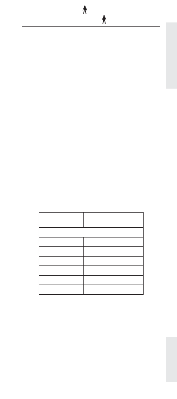
Gear Fast/Run Slow
Gear Fast/Run Super Slow
Description:
Gear Fast/Run Slow ( GFRS) and Gear Fast/Run Super
Slow ( GFRSS) are specing methods to promote improved
fuel economy through lower engine speed and faster
gearing. GFRS/GFRSS only applies for a multi-torque
rating allowing at least a 1750 lb-ft upper torque value.
GFRS/GFRSS is applicable for van, reefer, and tanker
applications, with a GVW of 80,000 lbs. The following
table matches axle ratios with the appropriate drive axle
tires revolutions per mile, specifi cally for the GFRSS
designation.
While GFRS/GFRSS is not an electronicallyprogrammable parameter, it has been included in this
handbook to supplement the Eaton Top 2 transmission
programming parameters. The results of employing
GFRS/GFRSS can be seen by entering appropriate data
into Cat Design Pro.
Available:
C-15, C-16, C13, C15 heavy duty engines
(Provided suffi cient torque is available - see
recommendation below)
Engine/Gear Parameters
Range:
Axle Ratio
1300 - 1350 RPM @ 65 MPH
3.21 513 to 531
3.25 506 to 525
3.36 490 to 508
3.42 481 to 499
3.55 464 to 480
3.58 460 to 476
Drive Axle Tires
Revolutions/Mile
Recommendations:
✔ Caterpillar recommends that the engine have at
least 1750 lb-ft of torque available for GFRSS
Page 87
Page 89

AT/MT/HT Part Throttle Shift Speed
Description:
The AT/MT/HT Part Throttle Shift Speed parameter
provides the ability to change the shifting
characteristics in vehicles equipped with non-data
link capable Allison transmissions. The Allison AT/
MT/HT (nonelectronic) transmissions require an input
from the engine ECM to regulate transmission shifting.
The ECM monitors accelerator pedal position, engine
Engine/Gear Parameters
speed, load, and cruise control status to determine if the
transmission should use closed throttle or full throttle
shift modulation.
Programming the Transmission Style parameter to
one of the AT/MT/HT options activates ECM Output #7
(J1/P1:20) to control a shift interface relay connected
to the transmission. The ECM can then energize the
output when the transmission should use full throttle
modulation (performance mode) or disable the output
when the transmission should use closed throttle
modulation (economy mode).
Available:
3126E, C7, and C9 medium duty engines. Not available on
2007 and newer engines.
Range:
Alternatives Default
Low (80% Enable/ 65% Disable)
Medium (70% Enable/ 55% Disable)
High (60% Enable/ 45%
Disable)
Advantages:
This parameter provides additional control over shifting
characteristics of the non-data link capable Allison
transmissions. This additional control enables a driver
to optimize the transmission’s behavior depending upon
the specifi c application.
Disadvantages:
None
Page 88
Page 90

Governor Type
OEM
Description:
Caterpillar offers three governor options, selectable with
the Governor Type parameter. These three options are
the Full Range Governor, and two types of the Min/Max
Governor.
Full Range Governor
This governor type allows the engine to maintain engine
speed for a given throttle position. The Full Range
Governor is capable of injecting the maximum amount of
fuel for a given desired engine speed.
The Full Range Governor is very sensitive to
changes in engine speed, and is therefore not the
preferred governor type for vehicles using automatic
transmissions. For example, if the ECM wants to
maintain 1500 rpm, the governor will try to maintain
the desired speed. When an automatic transmission
performs an upshift, the actual engine speed will fall
below the desired engine speed of 1500 rpm. The Full
Range Governor would then inject a large amount of
fuel in an attempt to increase the engine speed back
up to the desired engine speed of 1500 rpm. This
causes undesirable, harsh shifting with an automatic
transmission.
Min/Max Governor
The Min/Max Governor, however, is well-suited for
vehicles with automatic transmissions. The Min/
Max governor will only control engine speed when
at the minimum (low idle) or maximum (top engine
limit) allowed engine speed. When in between these
two extremes, the engine will produce the power
proportional to the throttle position. This results
in smoother shifting with automatic/automated
transmissions.
Engine/Gear Parameters
The Min/Max Governor optimizes automatic
transmission shift quality and power modulation,
allowing the operator to adjust the engine power output
to match typical vehicle operating conditions. The
engine speed will vary to fi nd a vehicle load level which
will match the engine power output specifi ed by the
throttle. If the throttle is commanding more power than
the vehicle load will offer, the engine will accelerate
to the top engine limit. This makes it very diffi cult to
maintain a constant engine speed when the vehicle is
parked. Slightly depressing the throttle pedal with the
vehicle parked will cause the engine to go to the top
engine limit, which may be undesirable for applications
that require precise engine speed control while parked.
This problem can be solved by the third governor type.
Page 89
Page 91

Min/Max Governor with Speed Control
The Min/Max Governor with Speed Control offers the
best combination of the Full Range Governor and the
Min/Max Governor. It provides smooth shifting with
automatic/automated transmissions while driving,
and precise engine speed control when the vehicle is
parked.
Available:
Engine/Gear Parameters
All electronically controlled on-highway engines
covered in this handbook (Note: Excludes C-10, C-12,
C-15, C-16 PM OCT01)
Range:
Engine Range Cat Default
3126E, C7, C9
(PM MAR03 and before)
C-10, C-12, C-15, C-16
(PM JAN02 - PM OCT02)
3126E, C7, C9
(PM MAR 04 and after)
C11, C13, C15
Min/Max
Full Range
Min Max
Min/Max with
Speed Control
Full Range
Advantages:
The Governor Type parameter allows the operator
to customize engine speed control by specifying the
appropriate governor for the selected transmission
type. When the Governor Type is properly set as
recommended below, optimum engine speed control is
achieved.
Full Range
Full Range
Disadvantages:
None
Recommendations:
✔ The Full Range Governor is recommended for
vehicles with manual transmissions.
✔ The Min/Max Governor is recommended for
vehicles with automatic/automated transmissions.
✔ The Min/Max Governor with Speed Control
is recommended for all automatic/automated
transmission-equipped vehicles with that require
precise engine speed control when parked.
Page 90
Page 92

Transmission Neutral Start Interlock
OEM
Description:
The Transmission Neutral Start Interlock allows the
engine ECM to monitor the J1929 ETC #7 message from
the transmission coltroller to either enable of disable the
engine from cranking. The Engine Running Output must
be programmed to a low side driver (J1/P1: 29, 30, or 31)
and the Powertrain Datalink must be programmed to
J1939 for this feature to function.
Programming the Neutral Start Interlock parameter to
Enabled when the ETC #7 message is not present or a
failure of the J1939 datalink, will result in the engine not
starting.
Available:
EPA’07 and newer C7, C9, C13 and C15 engines.
Range:
Range Cat Default
Enabled
Disabled
Disabled
Advantages:
Allows integration of the truck controller and the engine
controller to assure proper starting procedure.
Engine/Gear Parameters
Recommendations:
✔ This parameter should be enabled when using an
automatic transmission.
Page 91
Page 93

Emissions Parameters
Factory Databook Optional
• ARD Programmable
Regeneration Monitoring
System .................................... ✔
• ARD Fan Enable Vehicle
Emissions Parameters
Speed Threshold ................... ✔
• ARD PTO Mode Stationary
Regeneration Enable ............ ✔
• Malfunction Indicator Lamp
Confi guration ......................... ✔
• Data Link ARD Disable ......... ✔
• Number of Diesel Particulate
Filters ...................................... ✔
• Diesel Particulate Filter #1
Serial Number ....................... ✔
• Diesel Particulate Filter #2
Serial Number ....................... ✔
• ARD Fuel Nozzle Heater
Confi guration ......................... ✔
OEM
Page 92
Page 94

ARD Programmable Regeneration Monitoring
System
Description:
The ECM monitors the soot level in the Diesel Particulate
Filter (DPF). When the soot reaches a level that could
potentially damage the Caterpillar Regeneration
System (CRS), the ECM uses the ARD Programmable
Regeneration Monitoring System to determine the level
of action to take.
Available:
EPA’07 and newer C7, C9, C13 & C15 on-highway engines
Range:
*Warning is only available for emergency horsepower ratings only.
Advantages:
Prevents engine and Caterpillar Regeneration System
(CRS) damage. Derate allows truck time to travel home
or to the shop
OEM
Engine Range
EPA’07 and
newer C7,
C9, C13 &
C15
Warning*
Shutdown
Derate
Cat
Default
Shutdown
Emissions Parameters
Disadvantages:
None
Recommendations:
✔ Take truck to Cat Dealer to have DPF cleaned
Page 93
Page 95

ARD Fan Enable Vehicle Speed Threshold
Description:
The ARD Fan Enable Vehicle Speed Threshold defi nes
the vehicle speed the engine fan will be turned on if
vehicle speed falls below the programmed vehicle
speed and a regeneration of the DPF is active.
Available:
EPA’07 and newer C7, C9, C13 & C15 on-highway engines
Emissions Parameters
Range:
Engine
EPA’07 and newer C7,
C9, C13 & C15
Note: Programming this value to 0 (zero) will disable this
feature
Advantages:
Maintains cool engine throughout regeneration
Disadvantages:
None
Range
Minimum Maximum
0 mph
(0 km/h)
127 mph
(204 km/h)
(32 km/h)
Cat
Default
20 mph
OEM
Recommendations:
✔ Use the default setting of 20 mph (32 km/h) unless
your application requires the fan to turn on sooner.
Page 94
Page 96

ARD PTO Mode Stationary Regeneration
Device Enable Status
Description:
The Aftertreatment Regeneration Device (ARD)
PTO Mode Stationary Regeneration Device Enable
Status parameter allows the operator to decide if a
regeneration of the Diesel Particulate Filter ( DPF) will be
allowed during PTO Mode operation.
If programmed to Enabled, a regeneration can be
performed by using the Caterpillar Regeneration System
Force Switch. PTO Mode must be active and engine
speed between 1000 and 1850 RPM for regeneration to
occur.
Note: To enable this parameter, Factory Passwords are
required.
Available:
EPA’07 and newer C7, C9, C13 & C15 on-highway
engines
Range:
Engine Range
Cat
Default
Emissions Parameters
EPA’07 and newer C7,
C9, C13 & C15
Enabled
Disabled
Disabled
Advantages:
Allows semi-automatic regeneration during PTO
operation.
Disadvantages:
None
Recommendations:
✔ Set to Disable unless the application requires a
signifi ciant amount of time in PTO mode.
Page 95
Page 97

Malfunction Indicator Lamp Confi guration
Description:
An OEM installed Malfunction Indicator Lamp (hard
wired or J1939 driven) is used to indicate an emissions
or aftertreatment control system malfunction (diagnostic
condition) to the driver. The MIL Lamp is only illuminated
for diagnostic codes that affect emissions. The Amber
Warning Lamp may also be illuminated.
Emissions Parameters
Available:
Euro IV on-highway engines only
Range:
Engine Range
J1/P1: 10, 11,
Euro IV only
12, 13, 19, 20
J1/P1: 29,
30, 31
Advantages:
Allows OEM fi xability in wiring of the MIL Lamp option.
Disadvantages:
None
High Side Driver
Low Side Driver
Cat
Default
None
OEM
Recommendations:
✔ OEM will determine if this option is installed and
which ECM pin it will be wired.
Page 96
Page 98

Data Link ARD Disable Status
Description:
This parameter allows a technician to disable
a regeneration from occurring for service or
troubleshooting. A diagnostic code will be Active
and the Amber Warning Lamp illuminated while this
parameter is programmed to Disabled.
Note: If the key power is cycled from off to on the
Aftertreatment Regeneration Device Manual Disable
parameter will not go back to its default value of Not
Disabled (Regeneration will be disabled).
Available:
EPA’07 and newer C7, C9, C13 & C15 on-highway engines
Range:
Engine Range
EPA’07 and newer C7,
C9, C13 & C15
Disabled
Not Disabled
Cat
Default
Not Disabled
Advantages:
Allows the service techinician a convenient method
to disable the Caterpillar Regeneration System during
servicing.
Emissions Parameters
Disadvantages:
Technician must reprogram this setting to Not Disabled
before returning the vehicle to normal operation in order
for the Caterpillar Regeneration System to function
normally.
Recommendations:
✔This parameter should only be used by a qualifi ed
service technician in conjunction with the
diagnosing and repair of the engine.
Page 97
Page 99

Number of Diesel Particulate Filters
OEM
Description:
Indicates how many Particulate Filters are installed on
the chassis exhaust system. It is imperative the number
of aftertreatment particulate fi lters be programmed
correctly for the Caterpillar Regeneration System to
function properly.
Emissions Parameters
Available:
MY2007 C7, C9, C13 & C15 on-highway engines.
For MY2008 and newer engines this parameter is
programmed at the factory and can not be changed.
Range:
Engine Range
EPA’07 and newer C7,
C9, C13 & C15
1 or 2 1
Cat
Default
Recommendations:
✔The value of this parameter must be set to the
number of Diesel Particulate Filters (DPF) that are
on the vehicle.
Page 98
Page 100

Diesel Particulate Filter #1 Serial Number
Diesel Particulate Filter #2 Serial Number
OEM
OEM
Description:
Diesel Particulate Filter (DPF) #1 Serial Number and, if
applicable, DPF #2 Serial Number must be entered to
match the installed DPFs. Each DPF is equipped with a
resistor pack inside the DPF sensor housing. The ECM
auto-detects the installed DPF(s) and verifi es the correct
DPF(s) has been installed.
If an incorrect DPF is installed, a diagnostic code of
3936-2: Aftertreatment DPF System Incorrect will be
active. The engine will also be derated until a valid DPF
is installed or the correct DPF Serial Number is entered
using the Caterpillar Service Tool.
Available:
EPA’07 and newer C7, C9, C13 & C15 on-highway engines
Range:
Engine Range
EPA’07 and newer C7,
C9, C13 & C15
N/A 0000
Cat
Default
Emissions Parameters
Advantages:
Entering the proper DPF serial number(s) ensures the
correct size fi lters have been installed.
Recommendations:
✔This parameter should only be programmed by a
qualifi ed service technician as part of the normal
diesel particulate fi lter (DPF) maintenance.
Page 99
 Loading...