

Page 1
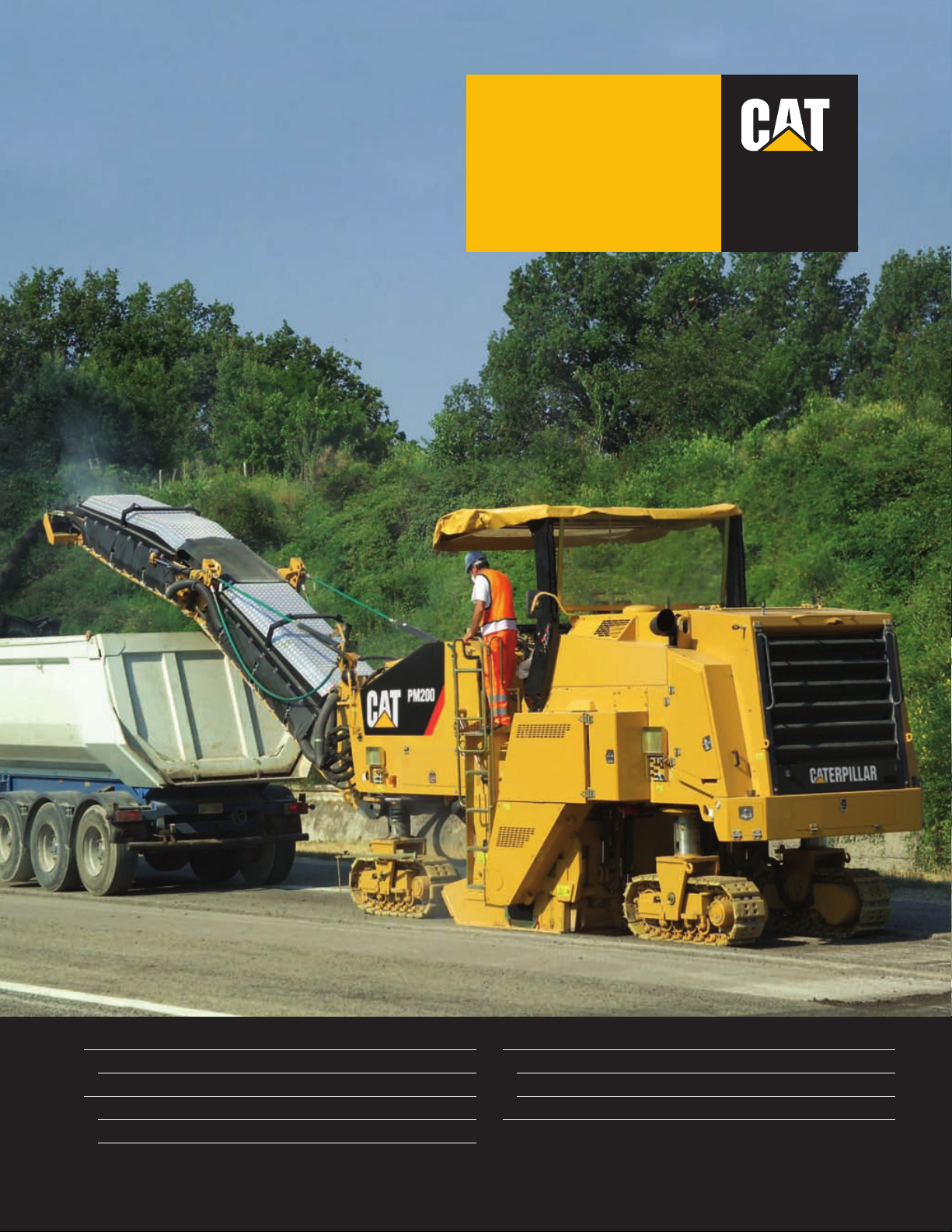
Rotor Widths
Standard 2010 mm
Optional 2235 mm
Rotor Depth (maximum) 320 mm
PM200
Cold Planer
®
Cat®C18 Engine with ACERT®Technology
Rated Power (ISO 14396) at 1900 rpm 429 kW/583 hp
Operating Weight
with 2010 mm Rotor 30 100 kg
with 2235 mm Rotor 31 500 kg
Page 2
2
PM200 Cold Planer
The new PM200 combines enhanced production capabilities, optimized performance
and simplified service to complete tough milling applications with productive results.
C18 Engine with ACERT Technology
ACERT Technology works at the point
of combustion to optimize engine
performance and provide low exhaust
emissions. The C18 engine with
ACERT Technology provides clean
burning power. pg. 4
Rotor Drive
A Cat®wet clutch with automatic belt
tension adjustment delivers efficient and
reliable power to the pavement. The
rotor drive consists of field-proven
Caterpillar components for long service
life. pg. 6
Propel System
Propel pump provides balanced flow to
dual displacement drive motors on each
track. Provides superior tractive effort
on slippery surfaces. The electronically
controlled load sensing system matches
propel speed to load on rotor for
maximum production. pg. 5
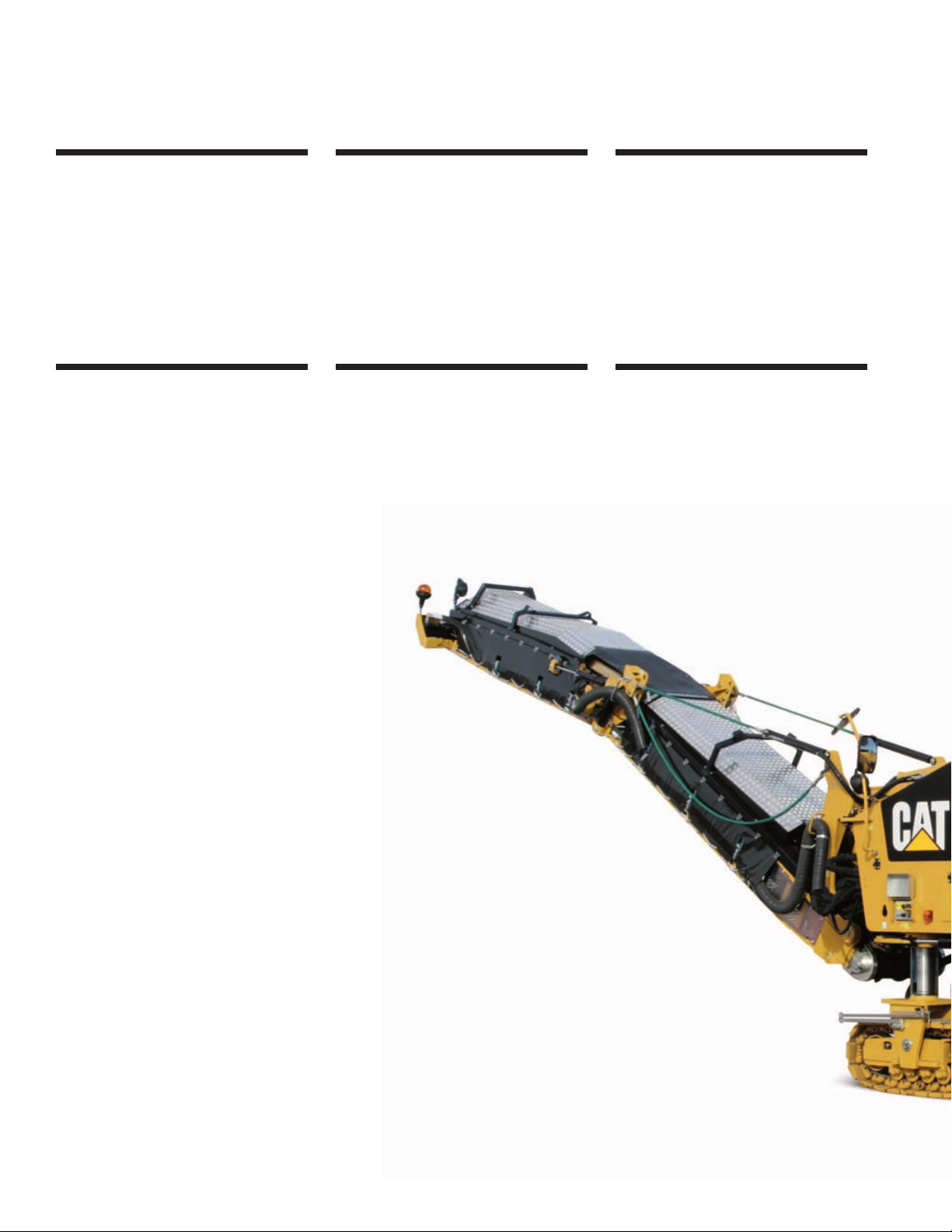
Front Loading Conveyor
The PM200 features a hydraulically
folding front loading conveyor for easy
transportation. The conveyor swings
48 degrees to the left or right to meet
your job requirements. pg. 7
Anti-slab and Collecting Conveyor
A large discharge opening and wide
collecting conveyor belt clear out the
cutter box fast. Water spray system for
lubrication, cooling and dust reduction.
pg. 7
Rotors
Deep cut or fine cutting rotors (8 mm
tool spacing only) available with quick
release conical tool holders for quick
and easy tool replacement.
pg. 6
Performance and reliability you expect.
The PM200 combines superior performance
and reliability to achieve the most demanding job
specifications while maximizing machine uptime.
With many enhanced features and options,
the PM200 performs full-depth removal of asphalt
and concrete pavements with high productive results.
Page 3

3
Operator’s Station
Ergonomic design emphasizes comfort,
visibility and easy operation. Left and
right side machine controls are grouped
and conveniently located to enhance
operator productivity and reduce fatigue.
pg. 9
Maneuverability
Four steering modes: front, rear, crab
and coordinated enable the operator to
have complete control of the machine
position in tight milling applications.
The four-track drive provides productive
operation. pg. 8
Automatic Grade and Slope Controls
The optional grade and slope systems
provide precise control of rotor to
a preset cutting depth and cross slope.
Remote mounted control boxes allow
simple operation from either the
operator’s station or ground level.
pg. 8
Serviceability
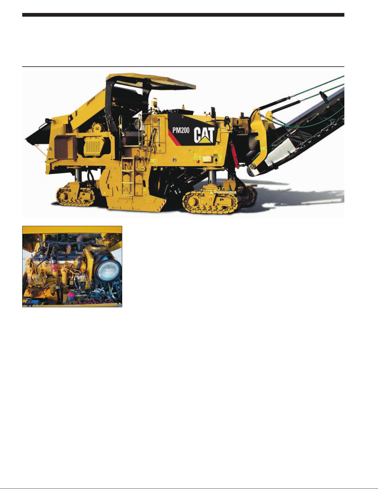
The power-assisted engine hood opens
wide and provides exceptional access to
the engine, hydraulic pumps and daily
service points. Hydraulic rotor service
door provides convenient access to the
rotor for easy cutting tool removal and
replacement. The rotor service door also
provides easy access to the water spray
nozzles for inspection and replacement
without the need for tools. pg. 10
Page 4
4
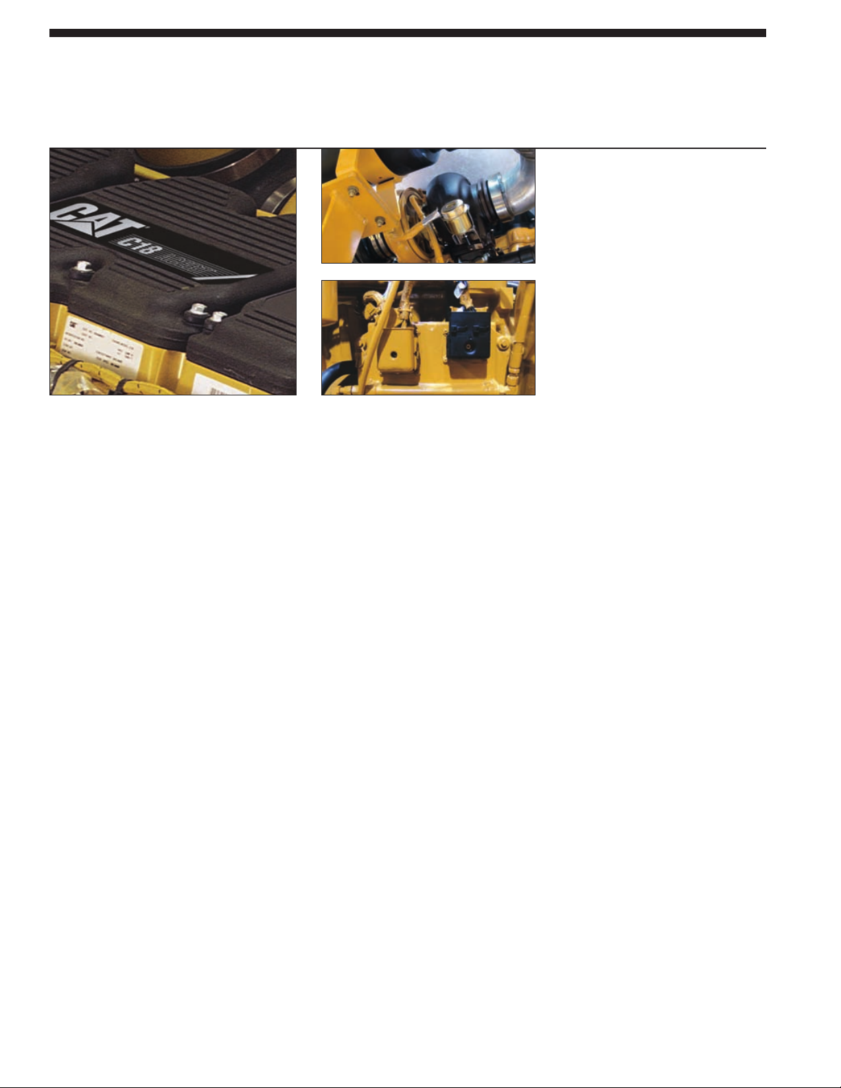
C18 Engine with ACERT Technology
A combination of innovations working at the point of combustion, ACERT Technology
optimizes engine performance while meeting European EU Stage IIIA emission regulations
for off-road applications.
Optimum power. The engine performs at a
full-rated gross power of 429 kW (583 hp)
at 1900 rpm with a torque of 2718 Nm.
The combination of large displacement and
high torque allow the PM200 to achieve
maximum production. Engine power curve
is optimized for milling applications
providing optimum power while keeping
the engine operating at peak efficiency.
High cylinder pressures. High cylinder
pressures combined with tightly controlled
tolerances promote extremely efficient fuel
burn, less blow by and lower emissions.
Mechanically-Actuated Electronically
Controlled Unit Injection (MEUI). The fuel
system is a unique system that combines
the technical advancement of an electronic
control system with the simplicity of direct
mechanically controlled unit fuel injection.
The MEUI system excels in its ability to
control injection pressure over the entire
engine operating speed range. These features
allow the C18 to have complete control
over injection timing, duration
and pressure.
Turbocharged and air-to-air
aftercooling. High horsepower with
increased response time is assured
while keeping exhaust temperatures
low for long hours of continuous
operation.
Air-to-air aftercooling (ATAAC).
Air intake temperatures are maintained
low and in concert with the tight
tolerance combustion chamber
components, maximizing fuel
efficiency and minimizing emissions.
New turbocharger, unique cross-flow
head design, single, front driven,
overhead cam and a more efficient
intake manifold generate significant
improvements in air flow,
maximizing efficiency and reduced
emissions.
The ADEM™ A4 electronic control
module. This module manages fuel
delivery, valve timing and airflow for
efficient performance per liter of fuel
used. The control module provides
flexible fuel mapping, allowing the
engine to respond quickly to varying
application needs. It keeps track of
engine and machine conditions while
keeping the engine operating at peak
efficiency.
Precise multiple injection fuel delivery.
Combustion chamber temperatures
are lowered by precisely shaping the
combustion cycle generating fewer
emissions and optimizing fuel
combustion; translating into more
work output for your fuel cost.
The C18 block. Single-piece, grey iron
block that features generous ribbing
for stiffness and heavy bearing
bulkheads for rigidity and strength as
the crankshaft turns. This new design
supports the engine’s higher compression
ratios and increases its power density.
The incorporation of straight-thread,
o-ring connection points reduces the
loss of engine oil and fluids.
Easier service, maintenance and repair
through monitoring key functions and
logging critical indicators. Advanced
electronic diagnostic capabilities are
possible using Cat Electronic
Technician.
Page 5
5
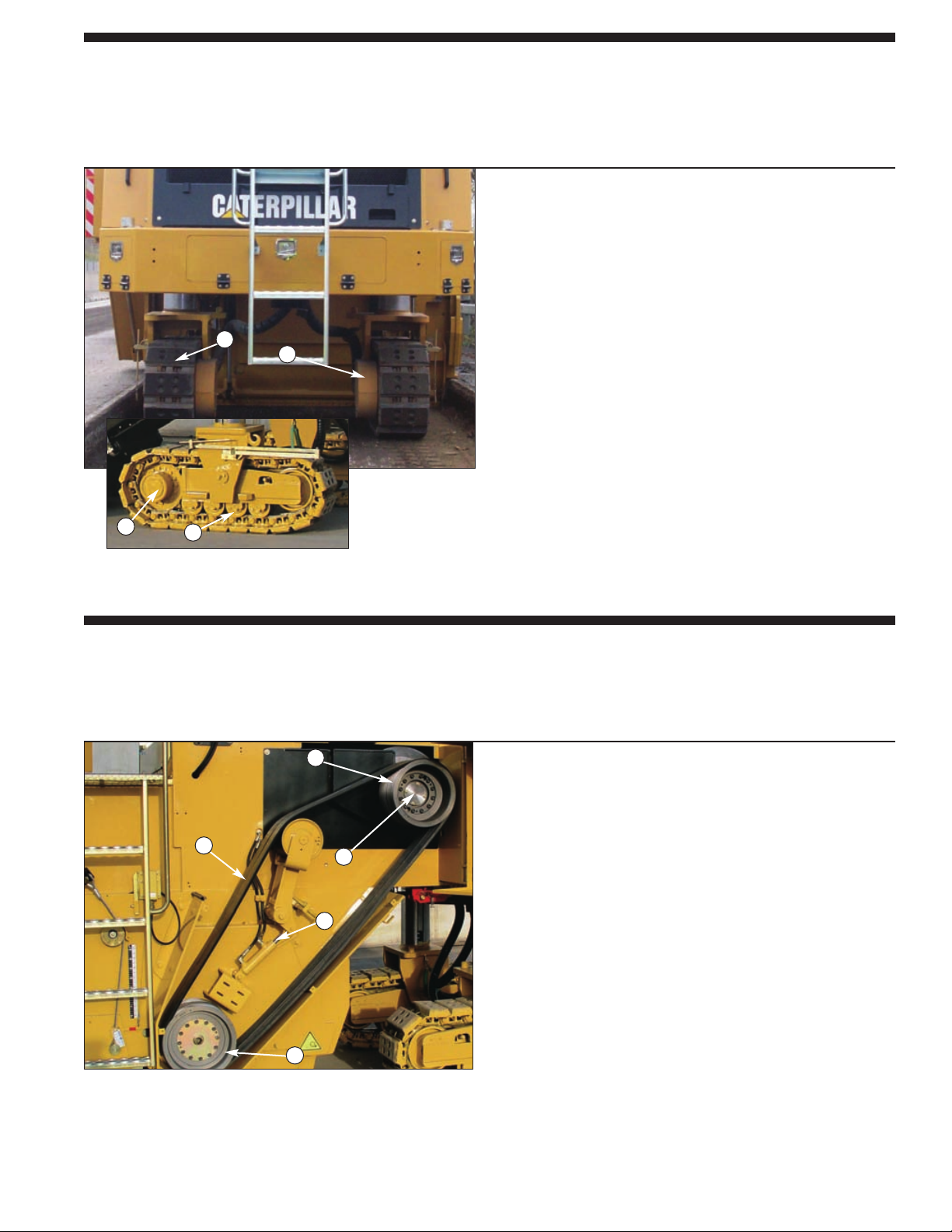
Propel System
Hydrostatic drive with hydraulic flow provided by a variable displacement axial piston
pump. Dual displacement track drive motors provide balanced tractive effort.
Propel pump. A balanced flow to the dual displacement
drive motors on each track provides superior tractive effort
on all surfaces.
Load control system (anti-stall). The electronically controlled
system matches propel speed to load on rotor for maximum
production. With the machine in work mode and load control
engaged, three load control settings can be selected – HIGH
for light cuts, MED for medium cuts and LOW for hard cuts.
The propel lever infinitely varies the working speed within
the three ranges.
Two speed ranges. The machine operates at either maximum
torque throughout the entire milling speed range or at a faster
travel speed for moving around the job site.
Positive traction control (flow divider). Equal hydraulic oil
flow to each drive motor increases tractive effort in hard
cutting applications and in slippery conditions. The positive
traction control is actuated from the operator’s console.
1
2
4
3
Rotor Drive
Exclusive Caterpillar wet clutch delivers maximum available horsepower to each cutting
tool while providing long service life and reliability.
Caterpillar wet clutch. The most efficient and reliable
system of applying rotor power to the pavement. The rotor
clutch system has a separate oil sump, pump, filter, clutch
control valve and oil cooler to provide continuous cooling
and lubrication.
Two cutting speeds. Upper and lower pulleys are easily
interchangeable for maximum torque with the toughest
materials and different material sizing requirements.
Two molded six-rib high tensile belts. High tensile belts
provide efficient transmission and long service life.
Automatic belt tension adjustment. The hydraulically
powered automatic drive belt tensioner prevents rotor
drive belt slippage and reduces maintenance.
1 Upper Pulley
2 Tension Cylinder
3 Molded Drive Belt
4 Lower Pulley
5 Input Pulley Shaft
1
5
2
3
4
1 Two Speed Drive Motor
2 Polyurethane Track Pads
3 Planetary with Secondary Brake
4 Heavy-duty Cat Rollers
Page 6
Rotors
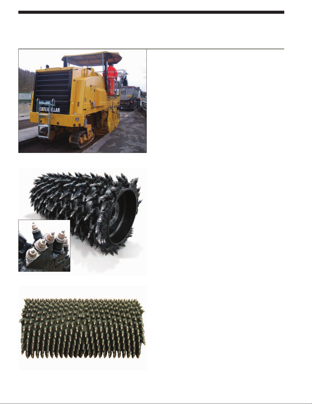
Caterpillar rotors with quick release conical holders for quick and easy replacement.
PM200 with 2.2 m rotor with option.
6
Standard 2.0 m rotor with quick
release three-piece tool holder.
Fine cutting rotor with 6 mm tool
spacing and welded tool holders.
2.0 m Rotor. Standard rotor width provides maximum
versatility and manueverability ideal for urban/city
application.
178 point-attack cutting tools
Cutting width: 2010 mm
Maximum cutting depth: 320 mm
2.0 m Fine Cutting Rotors Option. Optional fine cutting rotors
for removing either the wearing course, improving surface
traction or leveling surface irregularities. These fine cutting
rotors are available with a tool spacing of either 6 mm or
8 mm depending on the type of application. Maximum
cutting depth ranges from 50 mm to 80 mm.
2.2 m Rotor Option. Optional wider rotor provides maximum
productivity and efficiency during main line and high
production applications. Reduces passes and fuel burn.
193 point-attack cutting tools
Cutting width: 2235 mm
Maximum cutting depth: 320 mm
Point-attack carbide-tipped tools. Tools are mounted in
durable three-piece, quick release tool holders and arranged in a
triple wrap flighting pattern for maximum breakout force.
Tapered quick release conical tool holders maintain tightness
in holder base.
Large replaceable carbide faced loading paddles.
Loading paddles effectively move milled material onto
collecting conveyor resulting in higher production and less
wear on inside of rotor chamber and cutting tools.
Optimum tool spacing. Triple-tree tool placement on rotor
ends provides optimum tool spacing to clean up loose
material and reduces wear on rotor when maneuvering in the
cut.
Hydraulic side plates. Self-tensioning side plates can be
hydraulically operated from operator station and at ground level.
Additional Water Spray System for Dust Reduction. An
additional water spray system for additional cooling of the
cutting tools in hard applications and dust abatement. This
system consists of an extra water pump, a second spray bar in
the rotor chamber for additional cooling of the cutting tools
and extra spray nozzles for additional dust abatement on the
collecting and loading conveyors
Page 7
7
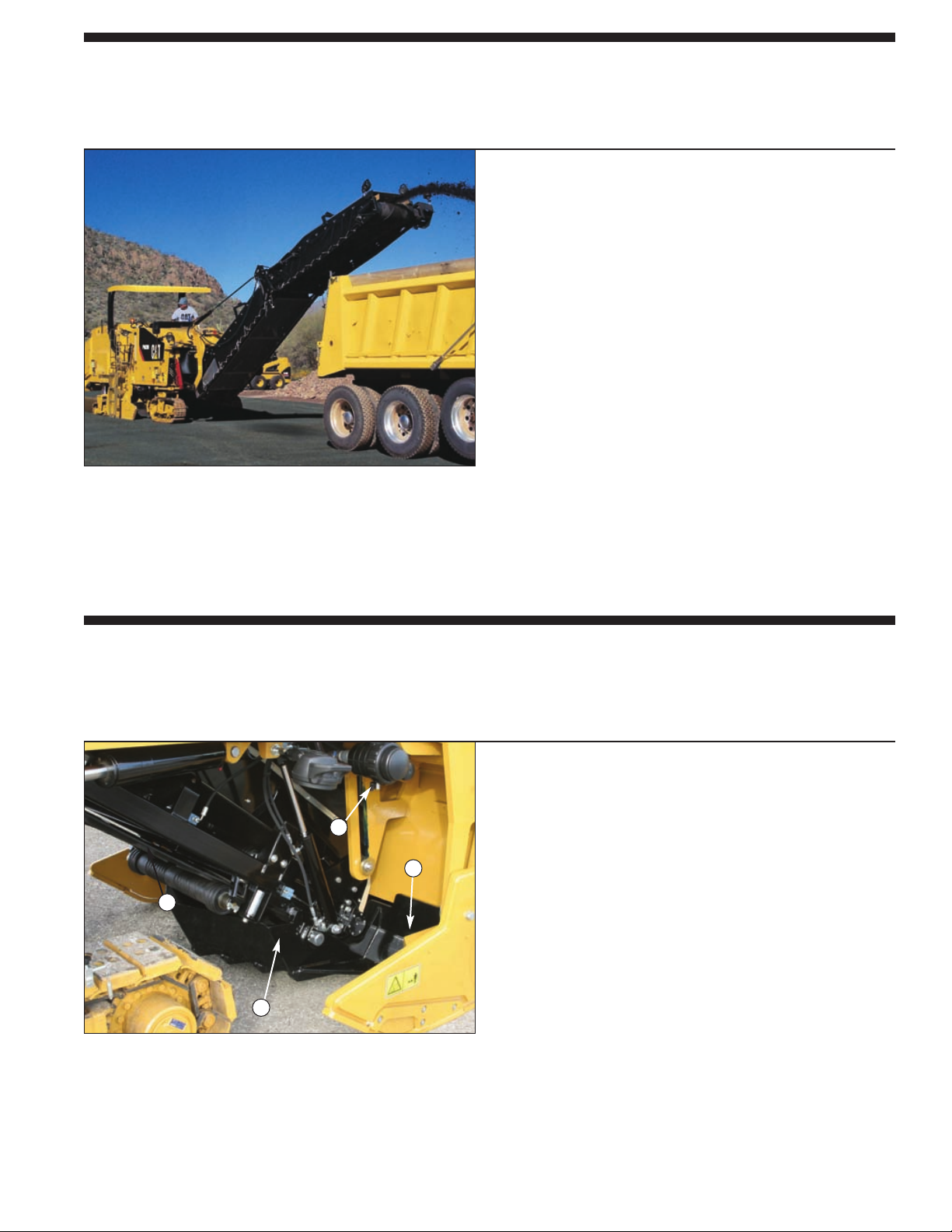
Anti-slab and Collecting Conveyor
A large discharge opening and wide collecting conveyor belt clear out the cutter box fast.
Water spray system for lubrication, cooling and dust reduction.
Optimum material sizing and gradation. The hydraulically
operated anti-slab device prevents slabbing of the road surface,
protects the collecting conveyor and ensures
an optimum discharge opening to the rotor chamber.
Large discharge opening. Rotor chamber is rapidly cleared for
increased production.
800 mm wide collecting conveyor. Driven by a high torque
hydraulic motor for maximum efficiency.
Variable belt speed. Collecting conveyor variable belt speed
controls loading of milled materials to closely match material
type and amount.
Optimum dust reduction. Standard pressurised water spray
lubricates and controls dust on collecting belt. Water spray
nozzles are easily accessed for inspection and replacement
without the need for tools.
Folding Loading Conveyor
High capacity and versatility add to increased jobsite productivity.
Hydraulic folding conveyor. Machine transportation is made
easier by the upward hydraulically folding front conveyor that
reduces the machine dimensions.
800 mm wide upper conveyor. Front loading conveyor height
adjustment is hydraulically controlled and two cylinders
provide a 48 degree swing to the left and right.
Seamless belt. Seamless belt with high cleats offers long
service life and provides better control of fine particles.
Variable belt speed. Front loading conveyor variable belt speed
controls loading of milled materials to closely match material
type and amount.
Optional dual water spray system. Additional lubrication and
cooling is provided for dust abatement during tougher cutting
applications. This system includes a second water pump
and extra spray nozzles that lubricate and control dust on
the loading and collecting conveyors.
1 Anti-Slab Device
2 Hydraulic Front Door
3 Water Filter
4 Seamless Belt
3
2
1
4
Page 8
8
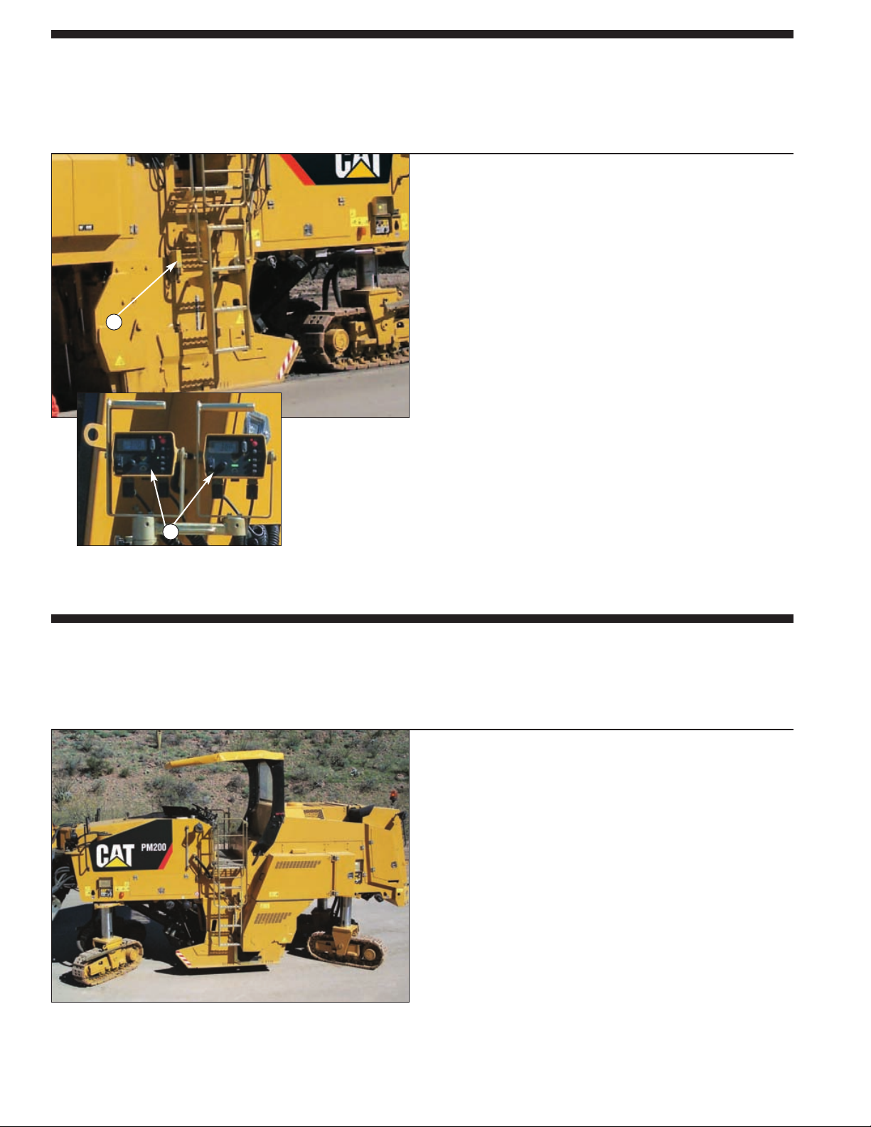
Contact or non-contact grade sensors. Sensors can be easily
positioned on each side of the machine and provide a consistent
accuracy. Cross-slope sensor adds to system versatility.
Wire (yo-yo) contacting grade sensors. Wire grade sensor
measures side plate movement that enables the entire length
of the side plate to become an averaging device for accurate
grade matching.
Remote mounted control boxes. Manual or automatic operation
can be carried out from either the operator’s station or at ground
level. Constant read-out for rotor depth and cross-slope are
easily visible even in direct sunlight.
Sonic Averaging System. This system features three noncontacting grade sensors, or one contacting and two noncontacting grade sensors, which mount on the side of
the machine, enabling the entire length of the machine to
become an averaging device.
1 Wire Controlled Contacting Grade Sensor
2 Remote Mounted Control Boxes
Automatic Grade and Slope Control Options
The optional contacting or non-contacting grade controls provide precise control of rotor
to a preset cutting depth. System can be configured to control grade or cross slope.
Four steering modes. Steering control provides four steering
modes for maneuvering in tight quarters: front steer, crab steer,
coordinated steer and rear steer.
Tight cutting radius. 2 m cutting radius allows for precise
milling on narrow city streets and cul-de-sacs.
Polyurethane track pads. Polyurethane track pads provide good
traction and improved durability against track pad separation.
Excellent visibility to the cutter box side plates.
Excellent visibility increases productivity and allows
the operator to precisely place the rotor against gutter pans
or when working near obstructions.
Dual propel levers. Infinitely variable machine speeds for
moving around the job site quickly.
Maneuverability
Four steering modes provide excellent handling for precise control and
increased production.
1
2
Page 9
9
Operator’s Station
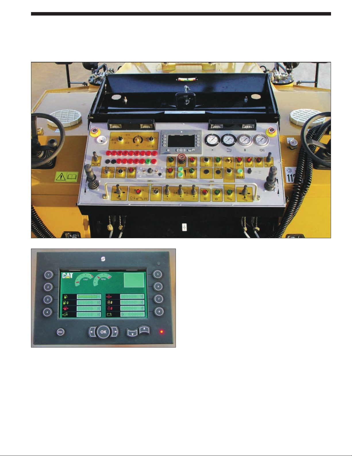
Designed for efficiency, productivity and simple operation from either side of the console.
Easy to reach controls minimize operator fatigue.
Dual operating controls. Clear control and instrumentation
layout designed for ease of use. All gauges and displays are
easily visible even in direct sunlight.
Computerized monitoring system. The system constantly
monitors system pressures and engine condition with multiple
modes of operation. Alerts the operator if a problem does
occur with three levels of event information.
Hydraulically operated canopy option. Full width canopy
with two side extending wings and front and rear windshields
provides optimum comfort and protection. Canopy can be
hydraulically lowered for transportation.
Optimum night lighting. Work area is efficiently illuminated
by a set of quick-fitting lights conveniently stored in one of
the machine’s compartments.
Visibility. An optional rear vision camera and Work Area
Vision System can be installed improving safety for the
operator, as well as other machines and personnel working
around the cold planer.
Page 10
10
Reliability and Serviceability
Reliability and serviceability are integrated into every Caterpillar machine.
These important features keep your machine investment profitable.
Hydraulic rotor service door.
Service door opens wide for convenient
access to rotor for inspection and tool
maintenance.
Electronic Control Module (ECM).
Machine systems are monitored
providing self-diagnostics for operator
or service personnel.
Three event levels. Operator is alerted
to conditions on the machine that
require attention. Encourages repair
before major failure.
Accessory drive system. In an engine
not running condition or nonoperational auxiliary hydraulic system,
full operational control of main
machine functions are readily available
for assisted machine movement for
maintenance and servicing.
Visual indicators. Visual indicators
allow easy check of water spray tank
level and hydraulic oil tank level.
Quick-connect hydraulic test ports.
Quick-connect feature simplifies system
diagnostics.
Ecology drains. Environmental method
to drain fluids. They are included on the
radiator, engine oil pan, hydraulic and
fuel tank.
S•O•SSMports. Scheduled Oil Sample
ports allow for simple fluid collection
of hydraulic oil.
Secure hose routing. Polyethylene
routing blocks provide a secure routing
to reduce rubbing and increase service
life of hoses.
Maintenance-free Caterpillar batteries.
Batteries are mounted at the rear of the
machine. Cat batteries are specifically
designed for maximum cranking power
and protection against vibration.
Cooling package. The cooling package
is a single plane design, stacked in
series for easy access for cleaning and
service. A modular stacked cooling
system provides more efficient cooling
of individual systems and makes routine
cleaning easier.
The power-assist engine hood opens
wide to provide optimum access
to the engine, air filter, hydraulic
components and daily service points.
Page 11

11
PM200 Cold Planer specifications
11
Engine
Six cylinder Caterpillar C18 with
ACERT Technology, turbocharged
air-to-air after-cooled diesel engine.
Meets European EU Stage IIIA
emissions control standards.
Net Power 1900 rpm
ISO 9249 415 kW/564 hp
Rated Power 1900 rpm
ISO 14396 429 kW/583 hp
Bore 145 mm
Stroke 183 mm
Displacement 18.1 liters
All engine horsepower (hp) are metric
including front page.
Net power ratings are tested
at the reference conditions for
the specified standard.
Net power advertised is the power
available at the flywheel when the
engine is equipped with alternator,
air cleaner, muffler and fan.
Dual-element, dry-type air cleaner
with visual restriction indicator, cold
mode starting aid and dual fuel filters
with water separator and air
compressor as standard.
Brakes
Primary Brake Features
Closed-loop hydrostatic drive provides
dynamic braking during normal
operation.
Parking Brake Features
Spring-applied/hydraulically-released
multiple disc type brake mounted on
each gear reducer. Brakes are applied
automatically when propel lever is in
the neutral detent position.
A loss of hydraulic pressure in
the brake circuit is caused when
the parking brake switch, located on
the operator’s console, is pushed in.
Parking brake is automatically
applied when the engine is shut
down.
Propel pump is de-stroked when
parking brake is engaged. Propel
lever must be returned to neutral
after brake is released before machine
will propel.
Steering
Hydraulic power-assist steering with
two steering wheels on operator’s
console. Four steering modes with
automatic realignment of rear tracks
through ECM is standard.
Features
Double-acting steering cylinders control
the front and rear tracks and are
powered by a pressure-compensated,
axial piston variable displacement
pump. Constant pressure is assured
in the steering system.
Switch on operator’s console
provides four steering modes.
Steering Modes
Front steer – controlled by the
steering wheel from both driving
positions. The ECM automatically
aligns rear tracks to the center
position for straight tracking.
Rear steer – controlled by joysticks
on operator’s console and toggle
switches at ground level control
panels. Rear steering is controlled
manually in this steering mode.
Crab steer – front and rear tracks turn
simultaneously in the same direction.
Coordinate steer – front and rear
tracks turn simultaneously in the
opposite direction.
Turning Radius
Minimum 2000 mm
Hydraulic System
Pumps for propel, rotor clutch
lubrication, collecting and upper
conveyors, auxiliary hydraulics
and cooling fan are installed on
the engine mounting pad.
Hydraulic oil cooler located at the rear
of the machine and arranged in
a modular stacked design for efficient
cooling and easy access for cleaning.
Three-micron filtration on pressure
side of auxiliary flow, seven-micron
filtration on return side.
Quick-connect hydraulic test ports
simplify system diagnostics.
Electrical
The 24-volt electrical system consists
of two maintenance-free Cat batteries.
Electrical wiring is color-coded,
numbered and labeled with component
identifiers. The starting system provides
1365 cold cranking amps (cca).
The system includes a 100-amp
alternator.
Frame
Fabricated from heavy gauge steel
plates and structural steel tubing.
Track assembly features track frame
stops to limit track angles to improve
machine’s ability to propel up steep
inclines and out of deep cuts. Top of
deck and steps features non-skid treads
for sure footing.
Page 12
12
PM200 Cold Planer specifications
Rotor Specifications
Rotor Drive System
Rotor drive Two six-rib high tensile belts
Transmission Mechanical
Clutch Hydraulic/wet multi-disc
Speed at 1900 engine rpm
Slow 109 rpm
Fast 119 rpm
Rotors 2.0 m Fine Cutting Rotors 2.2 m
Cutting width 2010 mm 2010 mm 2235 mm
Cutting depth 320 mm 50 mm/80 mm 320 mm
Tool spacing (tip) 15 mm 6 mm/8 mm 15 mm
Number of tools 178 670/274 193
Conveyor System
Collecting conveyor is driven by
a high torque hydraulic motor to
ensure maximum production and
clearing out the rotor chamber
effectively.
Variable belt speed control for collecting and front loading conveyors
enable matching of
milled material size and production
for all applications. Both conveyor
belts can be reversed for quick
clean out of belts.
Hydraulically folding front loading
conveyor facilitates machine
transportation.
Upper aluminum covers on
loading conveyor helps avoid material
spillage and wind blown
fine materials.
Collecting Conveyor
Width 800 mm
Speed 300 mpm
Loading Conveyor
Width 800 mm
Speed 300 mpm
Swing (from center) 48 degrees
Propel System
Hydrostatic drive with hydraulic flow
provided by a variable displacement
axial piston pump. Drive motors with
planetary gear reduction on each track
provides balanced tractive effort.
Features
A variable displacement, axial piston
pump with electronic displacement
control supplies pressurized flow.
Positive traction control valve
provides equal hydraulic oil flow to
each drive motor to increase tractive
effort in hard cutting and slippery
conditions.
Two-speed hydraulic motors allow
operation at either maximum torque
throughout the entire milling speed
range or at a faster travel speed for
moving around the job site.
Gear selection controlled electrically
by a selector switch on the
operator’s console.
With the machine in work mode
and load control engaged, three load
control settings can be selected –
HIGH for light cuts,
MED for medium cuts and
LOW for hard cuts.
Infinitely variable machine speed
and direction of travel controlled by
propel lever.
Load control system, controlled by
Electronic Control Module (ECM),
matches propel speed to load on
the rotor for maximum production.
Tracks are 1640 mm long,
300 mm wide and feature replaceable
polyurethane track pads.
Max. Speeds (forward and reverse):
Operating 0-38 mpm
Travel 0-5.9 km/h
Rotor Drive System
Operates direct through a hydraulically
actuated, Caterpillar wet clutch driving
a planetary gear reducer.
Features
Heavy-duty wet clutch mounts
directly to the engine. Hydraulically
actuated by a ON/OFF switch on the
operator’s console.
The rotor clutch system has a separate
oil sump, pump, filter, clutch control
valve and oil cooler to provide
continuous cooling and lubrication.
Two six-rib high tensile strength
drive belts drive the rotor through
a drum drive gear reducer located
inside the rotor mandrel.
Hydraulically powered automatic drive
belt tensioner prevents rotor drive
belt slippage and reduces
maintenance.
Upper and lower pulleys are easily
interchangeable for maximum torque
with the toughest materials and
different material sizing requirements.
Single caliper with dual disc brake
installed on rotor drive output drive
shaft.
Page 13

13
PM200 Cold Planer specifications
Water Spray System
Centrifugal pump supplies water to
spray nozzles for dust control and belt
lubrication.
Water spray nozzles focuses the water
spray in a flat fan pattern
to the rotor for better cooling of
cutting tools. Nozzles are easily
removed for inspection and
replacement without the need
for tools.
Standard system includes gauges to
monitor water pressure, a low water
level indicator and water control
valves to conserve water usage.
Water tank can be filled from the top
of the machine or at ground level.
An optional water spray system is
available for additional lubrication
and cutting tool cooling and for
additional dust abatement during
heavy-duty cutting applications.
Water Tank
Capacity 3500 liters
Optional Grade and Slope Controls
Machine elevation – rotor depth and
cross slope is manually controlled by
operator. Automatic rotor depth and
slope control is optional and features
electronic over hydraulic control.
System can be configured with
contacting (yo-yo) or non-contacting
grade sensors. Slope sensor adds
versatility.
Features
Machine elevation controls located on
the operator’s console and at ground
level allows rotor depth and cross
slope to be controlled manually.
Visual depth gauge displays depth
of cut.
The optional AUTOMATIC grade and
slope control automatically controls
rotor depth and cross slope to a preset
cutting depth. Setting cutting depth
is easily accomplished first in manual
mode by using the adjustment knob
on the controller.
Remote mounted control boxes allow
manual or automatic operation from
either the operator’s station or at
ground level. A cross communication
function allows the operator to view
and change settings of control boxes
located on the opposite side of
the machine. This allows operators
a means to control both sides of
a job from a single location.
Constant read-out for rotor depth
and cross-slope are easily visible even
in direct sunlight.
Sonic grade control sensors can be
positioned on each side are easy
to position and provide a consistent
accuracy.
Contacting (yo-yo) grade sensor
measures side plate movement that
enables the entire length of the side
plate to become a mini averaging ski
for optimum grade matching.
Sonic Averaging System features
three non-contacting grade sensors, or
one contacting (yo-yo) and two noncontacting grade sensors,
which mount on the side of the
machine, enabling the entire length
of the machine to become an
averaging device.
Rotor Housing
Large discharge opening clears out the rotor housing fast for increased production
and reduced tool wear.
Side plates contact surface in anti-wear material for longer service life.
Floating moldboard with adjustable down pressure is standard and features a
replaceable cutting edge.
Height control for rotor door located at operator’s station and at two ground level
control stations.
Page 14
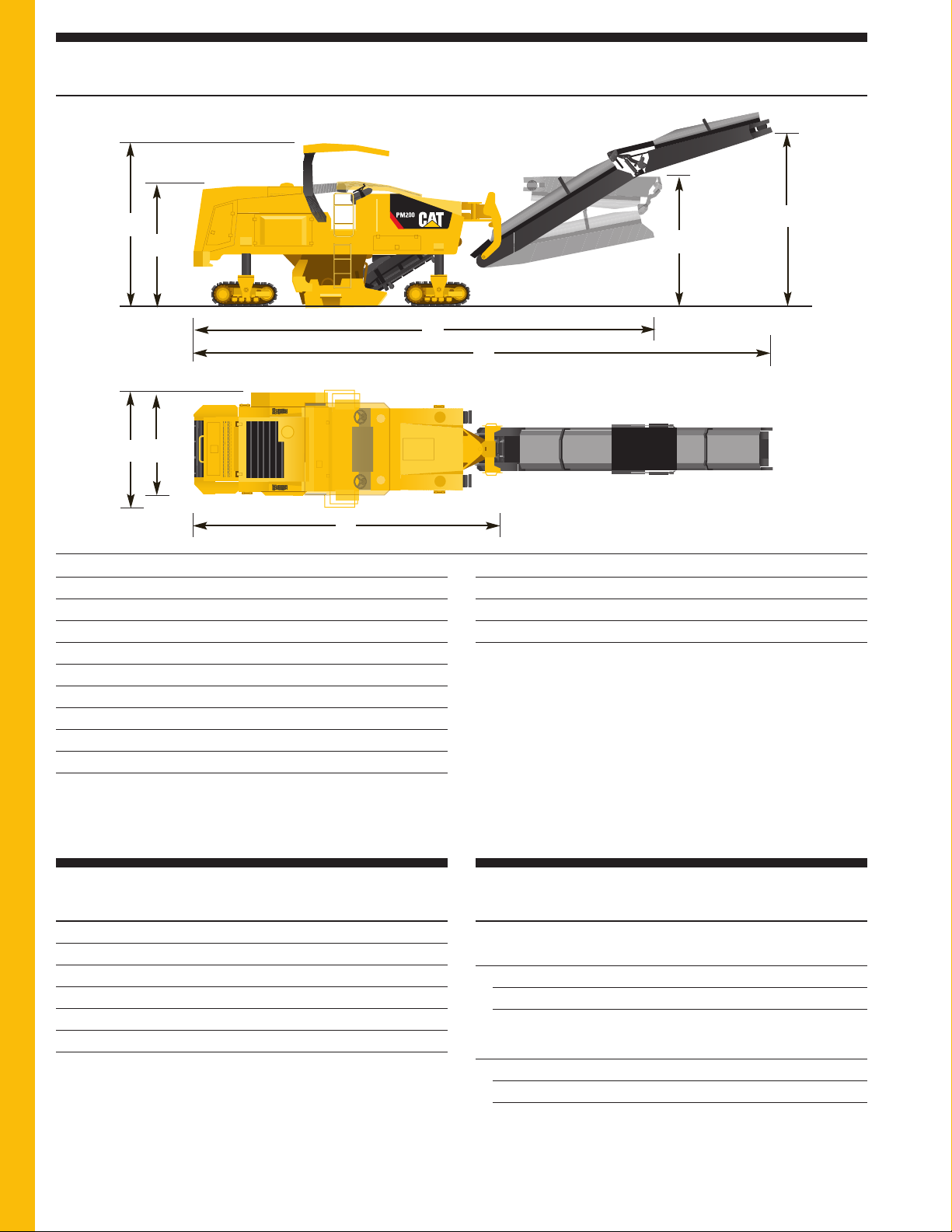
Operating mm
A Overall length (conveyor up) 13 940
B Overall machine width 2900
C Maximum height with canopy raised 3950
D Minimum height 2930
E Maximum truck clearance 4600
Rotor ground clearance 356
Conveyor swing 48° left or right of center
Collecting conveyor width 800
Upper conveyor width 800
Inside turning radius 2000
Shipping mm
F Length of base machine 7500
G Length with conveyor folded 11 380
H Height with conveyor folded 3150
I Maximum width with 2.0 m rotor 2500
Maximum width with 2.2 m rotor 2750
14
PM200 Cold Planer specifications
F
C
B
E
H
A
D
I
G
Dimensions
Weights
Operating Weights* w/2.0 m Rotor w/2.2 m Rotor
kg
Machine 30 100 31 500
on front tracks 15 600 16 400
on rear tracks 14 500 15 100
Shipping Weights**
Machine 28 000 28 600
on front tracks 12 650 12 950
on rear tracks 15 350 15 650
Weights shown are approximate and include:
* coolant, lubricants, 50% fuel tank, 50% water tank and a 75 kg operator.
** coolant, lubricants, 50% fuel level and empty water tank.
Service Refill Capacities
Liters
Fuel tank (useable) 1100
Engine oil w/filter 64
Propel planetary gear reducer (each) 1
Hydraulic tank 200
Rotor clutch sump 48
Water spray system 3500
Page 15

15
PM200 Cold Planer specifications
Optional Equipment
Some options listed may be an option in some areas and standard in others. Consult your dealer for specifics.
Hydraulically Operated Canopy.
Full width canopy with two side extending
wings and front and rear windshields
provides optimum comfort and protection.
Canopy can be hydraulically lowered for
transportation.
2.0 m Fine Cutting Rotors Option.
Optional fine cutting rotors for
removing either the wearing course,
improving surface traction or leveling
surface irregularities. These fine cutting
rotors are available with a tool spacing
of either 6 mm or 8 mm depending on
the type of application.
Maximum cutting depth ranges from 50
mm to 80 mm.
2.2 m Rotor Option. Optional wider rotor
provides maximum productivity and
efficiency during main line and high
production applications. Reduces passes
and fuel burn. 193 point-attack cutting
tools. Maximum cutting depth
320 mm.
High Pressure Washdown System.
This system uses water from the water
spray system to help with machine
clean-up at the end of each day’s
operation. System includes a spray wand
and hose with a quick-connect coupler.
Water Tank High Capacity Refilling
Pump. A hydraulic driven water pump
provides fast water tank refilling.
Additional Water Spray System for Dust
Reduction. An additional water spray
system for additional cooling of the
cutting tools in hard applications and
dust abatement. This system consists of
an extra water pump, a second spray bar
in the rotor chamber for additional
cooling of the cutting tools and extra
spray nozzles for additional dust
abatement on the collecting and loading
conveyors.
Electric Refueling Pump. An electric
powered fuel pump provides fast
refueling operations while the machine
is working without interruption.
Machine refueling can be carried out
even without starting the engine.
Ground Control Moldboard Pressure
Adjustment. Moldboard down-pressure
can also be adjusted and varied by
ground crew.
Pneumatic Tool. Pneumatic tool with
quick connect fitting and knockout
hammer for removing cutting tools.
Hydraulic Hammer Connection Ports.
Quick connect fitting for hydraulic
hammer.
Two Operator Seats. Two folding
cushioned seats provide for further
operator comfort during operation.
Seats can be folded to facilitate access
to engine compartment from the
operator’s station.
Automatic Grade and Slope System
automatically controls rotor depth and
cross slope to a preset cutting depth.
System can be configured with
contacting (yo-yo) or non-contacting
grade sensors.
Contacting (yo-yo) controlled grade
sensors measures side plate movement.
Non-contacting sonic grade sensors can
be configured using one sensor per side
or the Sonic Averaging System (SAS).
The Sonic Averaging System (SAS)
features three non-contacting grade
sensors, or one contacting (yo-yo)
and two non-contacting grade sensors,
which mount on the side of the
machine, enabling the entire length of
the machine to become an averaging
device. System also includes a crossslope sensor to meet slope applications/
requirements in job specifications.
WAVS Camera Ready. An optional rear
vision camera and Work Area Vision
System can be installed improving
safety for the operator, as well as other
machines and personnel working around
the cold planer.
Page 16

®
HEHG3267-2 (01/2010) hr
PM200 Cold Planer
For more complete information on Cat products, dealer services, and industry solutions, visit us on the web at
www.cat.com
Materials and specifications are subject to change without notice. Featured machines in photos
may include additional equipment. See your Caterpillar dealer for available options.
© 2010 Caterpillar -- All rights reserved
CAT, CATERPILLAR, their respective logos, “Caterpillar Yellow” and the POWER EDGE trade dress as well as
corporate and product identity used herein, are trademarks of Caterpillar and may not be used without permission.
 Loading...