

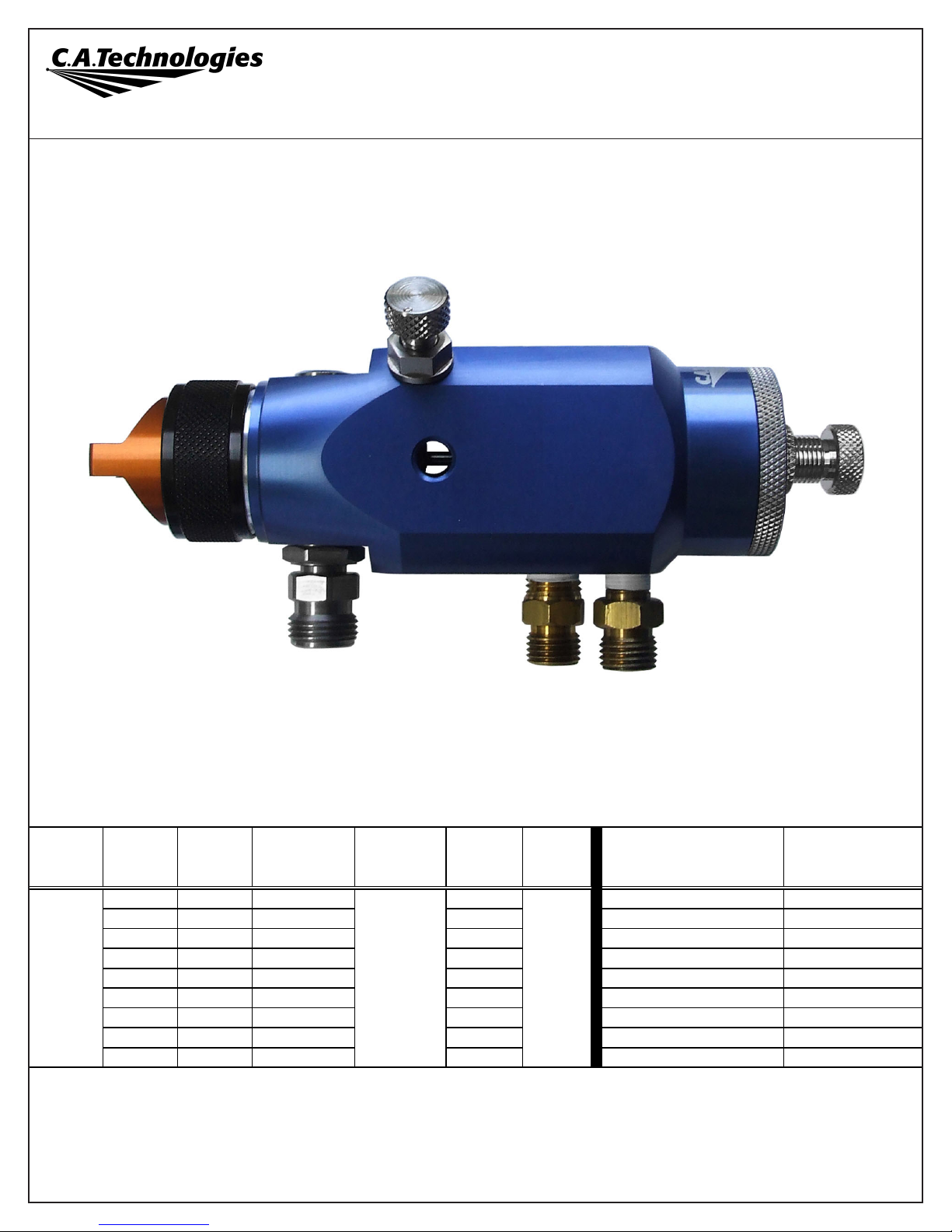
C.A.T. AutoCAT 300H Product Information
HVLP AIR CAP AND FLUID NOZZLE CHART
MODEL
NO.
AIR CAPS
Press /
Siphon
*MAX GUN
INLET PRES S.
FOR HVLP
FAN
CONTROL
ORIFICE
SCFM @
MAX GUN
INLET
AIR CAP
RING
AVAI LABLE F L U I D
NOZZLES TIPS
NEEDLES /
marking on needle
23-1008 pressure 40** 13.5 33-0208 0.8mm (.022")
40-A308 (308)
23-1010 pressure 40** 13.5 33-0210 1.0mm (.040") 40-A310 (310)
23-1012 pressure 40** 13.5 33-0212 1.2mm (.046") 40-A312 (312)
23-1013 pressure 40** 13.5 33-0213 1.3mm (.052") 40-A313 (313)
23-1014 pressure 40** 13.5 33-0214 1.4mm (.055") 40-A314 (314)
23-1015 pressure 40** 13.5 33-0215 1.5mm (.059") 40-A315 (315)
23-1017 pressure 40** 13.5 33-0217 1.7mm (.070") 40-A317 (317)
23-1019 pressure 40** 13.5 33-0219 1.9mm (.075") 40-A319 (319)
23-1022 pressure 40** 13.5 33-0222 2.2mm (.086") 40-A322 (322)
Actual fluid nozzle and air cap combinations are determined by application (see application chart page 4)
*Note: Air cap test gages are available to confirm HVLP compliance.
*Gun inlet pressures may vary as required by application
**When using optional gun regulator, inlet pressure changes to 45psi
IncludedA30 0H 60-617
AA
A
AA
utut
ut
utut
oCoC
oC
oCoC
AA
T 300HT 300H
A
T 300H
AA
T 300HT 300H
AUTOMATIC SPRAY GUN
PRODUCT INFORMATION
Coating Atomization Technologies 337 South Arthur Avenue, Louisville CO 80027 Phone: 888.820.4498, Fax: 303.438.5708
www.spraycat.com

Operation and Maintenance Instructions for
A300HA300H
A300H
A300HA300H
Spray Guns
Gun Mounting
A 1/2” dia. x 5” lg. rod is provided for mounting. The gun can be mounted from the left or right side or from the bottom.
Thread the mounting rod (9) into one of the three holes that best suit the mounting location for the application. Tighten
the locknut (10) to secure the gun in the position desired. Do not plug the remaining holes as they are used as drain
holes in the event of a needle seal leak.
Operation: Connections and Adjustments
The automatic gun requires two separate regulated air supply lines.
1. Connect one air line to the fitting marked “CYL”, this actuates the gun on and off and is usually connected through an
air solenoid.
2. Connect the second air line to the fitting marked “ATM”, this provides atomizing and fan air.
3. Connect a pressurized fluid supply to the gun fluid inlet.
4. Fluid flow can be controlled using the fluid control knob, this restricts flow by limiting needle travel. It is best to control
fluid flow by proper selection of fluid orifice size and use the fluid control knob to “fine tune flow rate”.
5. Fan width can be adjusted using the fan control knob. Turning the knob clockwise narrows the fan.
Maintenance: Needle Seal Replacement
IMPORTANT! Routine cleaning and maintenance is essential to insure proper gun operation.
Before beginning needle seal replacement, it is recommended kit no. 10-107 be on hand.
Several states prohibit spraying solvent into the atmosphere and require the use of covered gun cleaner.
1. Remove fluid control knob (36), needle return spring (34), and needle assembly (33).
2. Remove end cap (32) and piston return spring (31).
3. Piston (29) can be removed with pliers by carefully gripping the hub on the rear of the piston.
4. Remove the air control spool (22) using an 11/16” socket to unscrew it from the body.
5. The needle seal can be removed using a 7/16” socket with a short extension. Install a new needle seal and torque to
approx. 2 ft.-lbs.
6. It is recommended that the o-rings on the air control spool (22) and piston (29) be replaced and lubricated before
reassembling the gun.
NOTE: Gun head disassembly is not recommended for normal cleaning and maintenance.
Gun head disassembly and reassembly instructions:
Have repair kit # 10-107 available before gun disassembly.
Gun head disassembly
To remove the nozzle carrier (6) and air cap adapter (7):
1. Remove the air cap (1), fluid nozzle tip (3), fluid nozzle body (4), and needle (33).
2. Remove the needle seal cartridge (18) as described above.
3. Loosen the locknut (26) using 11/16” wrench and remove fluid inlet (27) using a 5/8” open-end wrench.
4. The nozzle carrier (6) and air cap adapter (7) will now slide forward from the gun body (11).
Gun head reassembly
1. Install a new o-rings (5 & 8) on the air cap adapter (7).
2. Install the thread locknut (26) onto the fluid inlet (27) as far as possible.
3. Install a new fluid inlet seal (25) into the recess area on the nozzle carrier (6) inlet port.
4. Slide the nozzle carrier (6) into air cap adapter (7) and insert into the gun body (11) as far as possible. Be sure the
nozzle carrier (6) extends into the hole at the back of the gun head. Install the needle seal (18) but do not tighten.
5. Rotate the nozzle carrier (6) until the fluid inlet port in the nozzle carrier (6) is aligned with the threaded hole in the
body. While in this position, insert the fluid inlet (27) and tighten firmly.
6. Tighten the needle seal (18) to approx. 12 ft.-lb. torque.
7. Tighten the fluid inlet (27) to approx. 25 ft.-lb. torque.
8. Tighten the locknut (26) to approx. 33 ft.-lb. torque.
 Loading...