

Page 1
SERVICE MANUAL
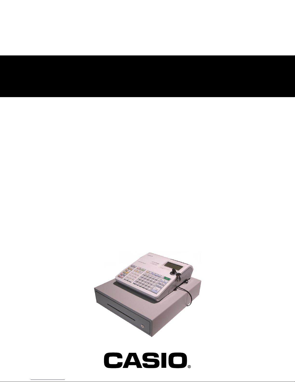
ELECTRONIC CASH REGISTER
SE-S300/S2000
SE-C300/C2000
TE-900/1500
TK-950/1550
PCR-T48S/T470/T480/T470L/T480L/
T220S/T2100/T2200/T2100L/T2200L
(EX-292/EX-293/EX-592/EX-593)
FEB. 2008
SE-S2000M
Ver.1 : Mar. 2007
Page 2

CONTENTS
PAGE
1. SPECIFICATIONS ...................................................................................................... 1
2. MACHINE INITIALIZATION ....................................................................................... 4
3. DISASSEMBLY .......................................................................................................... 9
4. BLOCK DIAGRAM ...................................................................................................17
5. DIAGNOSTIC OPERATION .....................................................................................18
6. ERROR CODE LIST ................................................................................................. 39
7. PCB LAYOUT ...........................................................................................................41
8. CIRCUIT DIAGRAMS ............................................................................................... 43
9. PARTS LIST .............................................................................................................52
Page 3
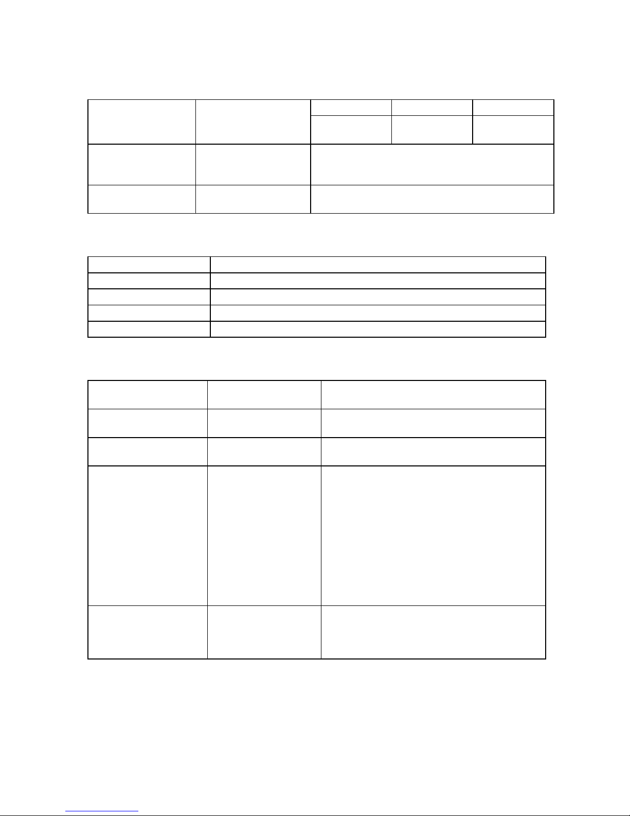
1. SPECIFICATIONS
1-1. Electrical specifications
• Power consumption
In operation
Display off
• Memory protection Back-up battery
Back-up period
Battery life
• Clock & Calendar Accuracy
Auto calendar
120 V 230 V 240 V
Max.
0.4 A
Max.
0.05 A
Two new size AA alkaline batteries
1 year (25 °C)
Replace the battery every 1 year.
Within ± 30 sec. per month (25 °C)
Effective until 2099 A.D.
0.26 A
0.04 A
1-2. Environmental specifications
• Operating temperature 0 °C ~ 40 °C
• Operating humidity 10 % ~ 90 %
• Storage temperature -25 °C ~ 65 °C
• Storage humidity 10 % ~ 95 %
• Drop Durability Durable through dropping one end of the unit from 3 cm in height.
1-3. Main components
• CPU Name
Number of control bit
• SRAM Name
Capacity
• FROM Name
Capacity
• Thermal printer Name
Print method
Head specification
Total dot number
Dot pitch
Paper supply method
Print wide
Roll diam
Type
• Roll paper Type
Size
Roll diam
Thickness
uPD70F3733GJ-UEN-A
32 bit
CY62146EV30LL-45ZSXIT
4 Mbit
S29JL032H70TFI020
32 Mbit
FTP-628MCL518 (Receipt)
FTP-628MCL518 (Journal)
Thermal dot line printing
384 dots/dot line
Lenght 8 dots/mm
Wide 8 dots/mm
57.5 ± 0.5 mm
Heat-sensitive paper
Heat-sensitive paper
57.5 ± 0.5 mm
Φ 80 mm or less
0.06 ~ 0.85 mm
0.26 A
0.04 A
— 1 —
Page 4

1-4. Drawer List
Type Drawer Name Specification Europe UK U.S.A. Canada Others
SE-S300
S DL-1842 D-21K2C-D53RM-17*
M DL-2800 D-24K2C-B84RM-9*
SE-S2000
M DL-2800 D-24K2C-B84RM-9*
M DL-2803 D-24K2C-B84SRM-9*
SE-C300
M DL-2806 D-24K2C-B84SRM-4*
M DL-2807 D-24K2C-B84RM-4*
SE-C2000
M DL-2806 D-24K2C-B84SRM-4*
M DL-2807 D-24K2C-B84RM-4*
TE-900
S DL-1332 D-21K2C-D54RM-4*
TE-1500
M DL-2433 D-24K2C-B55SRM-4*
TK-950
S DL-1332 D-21K2C-D54RM-4*
TK-1550
M DL-2433 D-24K2C-B55SRM-4*
PCR-T48S
S DL-1332 D-21K2C-D54RM-4*
PCR-T220S
M DL-2433 D-24K2C-B55SRM-4*
PCR-T470
S DL-1332 D-21K2C-D54RM-4*
PCR-T470L
M DL-2802 D-24K2C-A84RM-4*
PCR-T480
S DL-1331 D-21K2C-D54RM-17*
PCR-T480L
M DL-2801 D-24K2C-A84RM-9*
PCR-T2100
M DL-2433 D-24K2C-B55SRM-4*
PCR-T2100L
M DL-2805 D-24K2C-A84SRM-4*
PCR-T2200
M DL-2432 D-24K2C-B55SRM-9*
PCR-T2200L
M DL-2804 D-24K2C-A84SRM-9*
— 2 —
Page 5
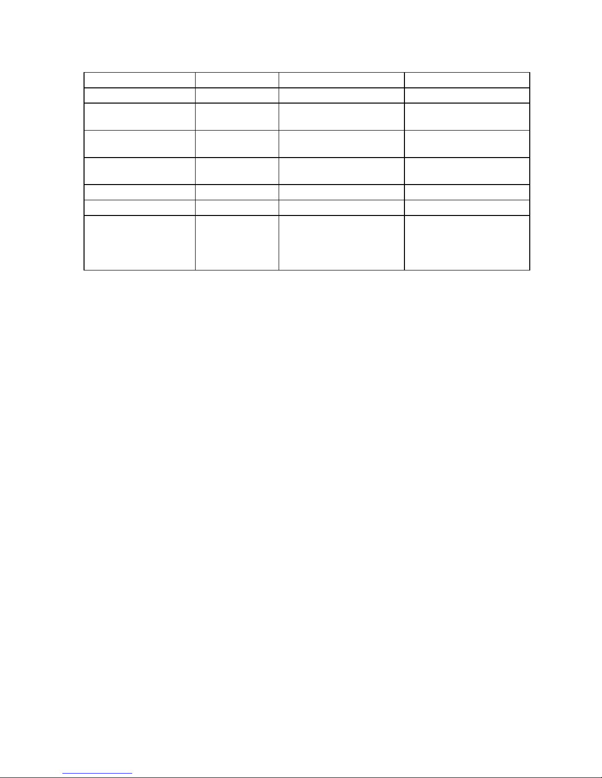
1-5. Option List
DEVICE NAME MODEL NOTE Applicable
Roll paper TRP-5880T Common
Waterproof cover WT-89 SE-S300/S2000,
TE-900/1500, PCR series
Waterproof cover WT-90 SE-C300/C2000,
TK-950/1550
Sheet cover WT-91 SE-C300/C2000,
TK-950/1550
PC cable PRL-CB-2 Common
External memory RAC-12B 4MB (Thermal pop) Common
External memory RAC-14B 16MB (Electronic journal) Common
CAUTION
RISK OF EXPLOSION IF BATTERY IS REPLACED
BY AN INCORRECT TYPE.
DISPOSE OF USED BATTERIES ACCORDING
TO THE INSTRUCTIONS
— 3 —
Page 6
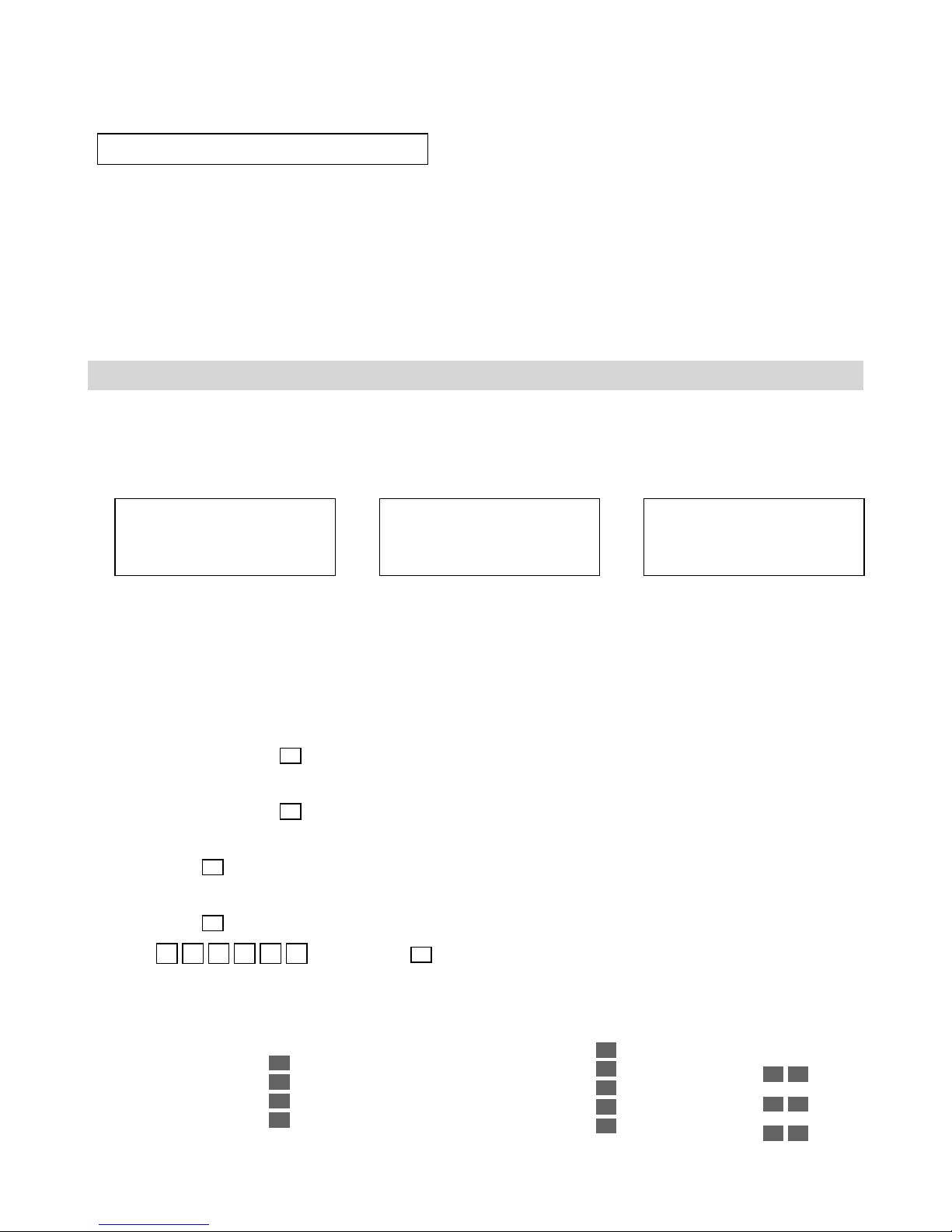
2. Initialization
Initializing the cash register
• Automatic initialization
Use the following procedure to initialize the cash register before using it for first time after you purchase it.
1. Install the two memory backup batteries (see page 10 of the User’s Manual).
2. Plug the cash register into a wall outlet.
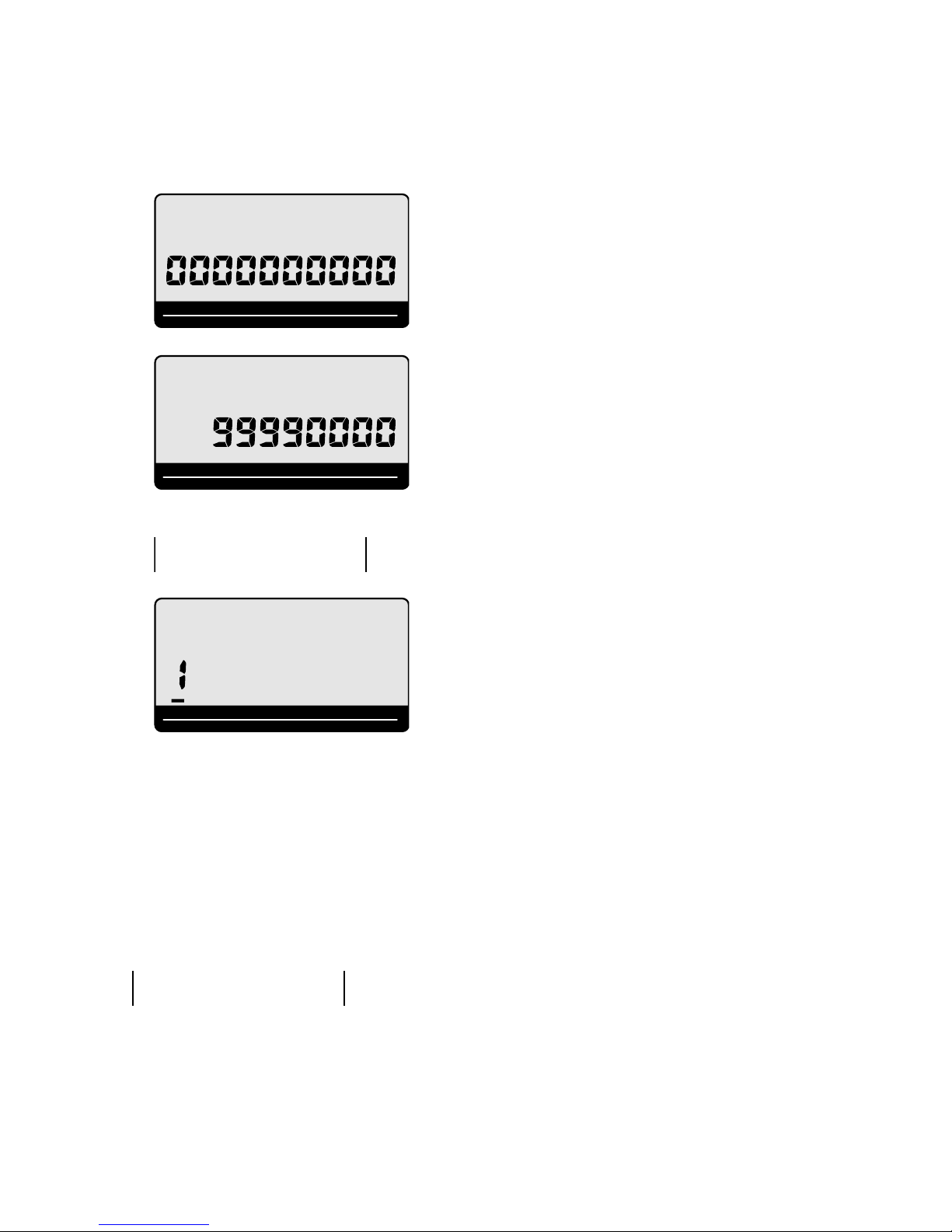
• At this time, "00000000" appears on the display and the printer operates for a minite. Initialization is complete
when the Printer stops operating.
CAUTION!
Automatic initialization (which clears all sales and programming data stored in the register’s memory) is performed
whenever all power (both the backup batteries and power through power cord) is cut form the cash register
and then restored. The program data stored in the flash memory is restored.
Remember...
Main power cut by:
•
Unplugging the cash register
• Power failure
Backup power cut off by:
+
• Removing the batteries
• Dead or low batteries
Automatic initialization when
the main power is restored
+
and the mode switch is set to
any position besides OFF.
• Manual initialization
Use the following procedure to initialize the cash register and clear all transaction data and program data
from its memory.
1. Insert the mode key marked “PGM” into the mode switch.
2. Turn the mode switch to the OFF position.
3. SE-S300/SE-C300:
While holding down the
SE-S2000/SE-C2000:
While holding down the
4. SE-S300/SE-C300:
Release the
FEED
key.
SE-S2000/SE-C2000:
JOURNAL
Release the
FEED
key.
5. Enter A B 0 0 and press the
FEED
key, turn the mode switch to the PGM position.
JOURNAL
FEED
key, turn the mode switch to the PGM position.
SUB
key.
TOTAL
A. Language selection
This specification defines the
language to use for the date in
receipt/journal printing.
English
French
Spanish
German
0
1
2
4
B. Area / monetary mode
This specification defines the area
and the decimal position.
U.S.
Canada
German
Two decimal place
No decimal place
— 4 —
2
9
4
1
3
C. Department number
This specification defines the
number of deparment keys.
Always
SE-S300
SE-C300/
SE-C2000
SE-S2000
2 5
7 2
3 0
Page 7

Clearing a machine lock up
If you make a mistake in operation, the cash register may lock up to avoid damage to programs and preset
data.
Should it happens, you can use the following procedure to clear the lock up without losing any data.
1. Power off the register.
2. Insert the PGM key in the mode switch.
3. SE-S300/SE-C300:
Press down and hold
SE-S2000/SE-C2000:
Press down and hold
4. SE-S300/SE-C300:
The display shows INIT (on alpha-display), then release
SE-S2000/SE-C2000:
The display shows INIT (on alpha-display), then release
SUB
5. Press
TOTAL
. A receipt is issued.
FEED
, and turn the mode switch to PGM mode.
RECEIPT
FEED
, and turn the mode switch to PGM mode.
FEED
RECEIPT
FEED
.
.
— 5 —
Page 8
2. Initialization
Load IPL data
•
When you replace a main PCB with a spare parts, load the IPL data to ECR as the following steps;
1. Required materials
RS232C cross cable which is using CV10
Memory pack RAC-12B
RAC_TOOL software
IPL data file
*Please contact CASIO sales division to get the above materials.
PC with RS232C COM port
Windows 2000 / XP / Vista
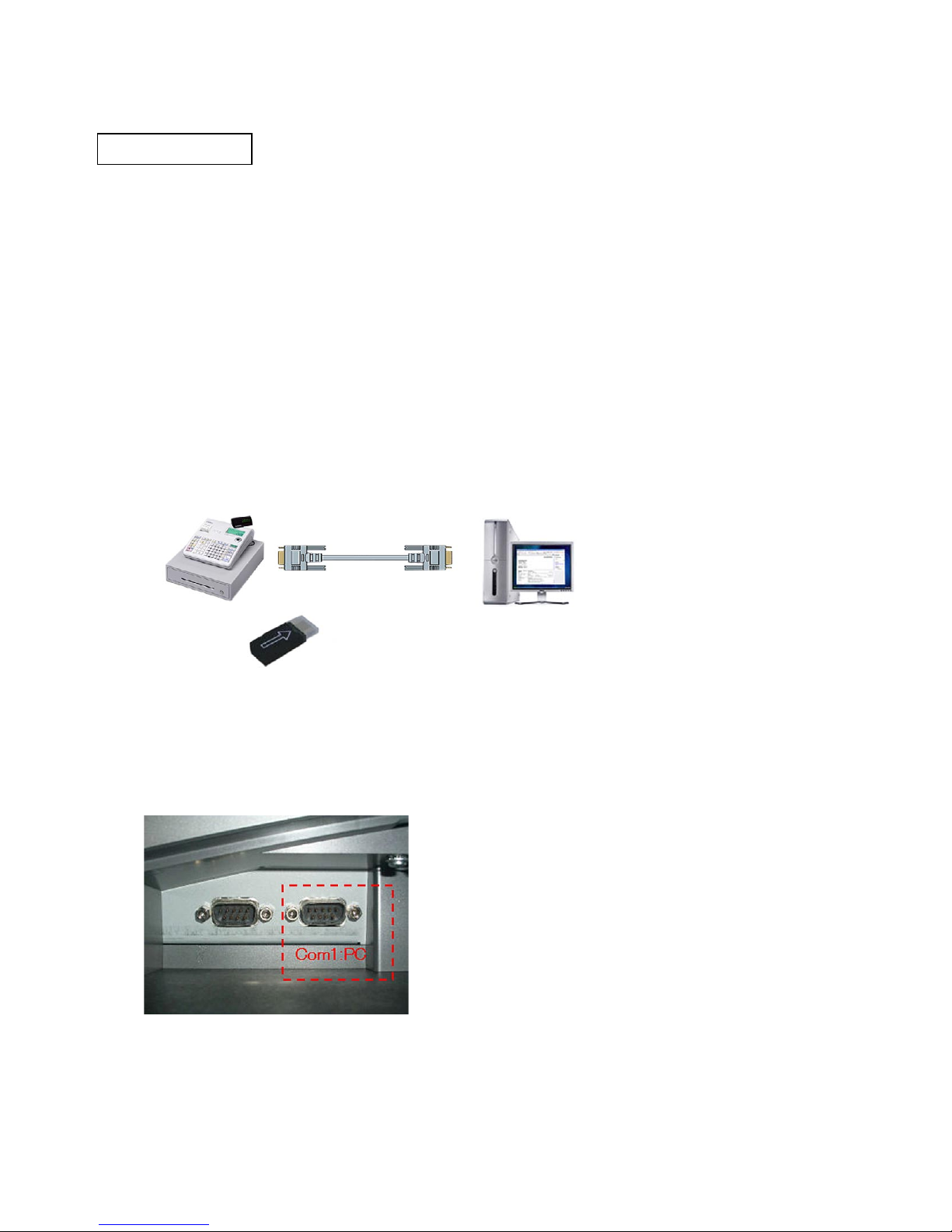
2. System configuration
SE series ECR
3. Steps to load IPL data
3-1. Write the IPL data to the RAC-12B from the PC. (Make a special RAC for IPL.)
1) Remove power cord of ECR from AC outlet.
2) Connect the ECR (COM1 port) and PC with the RS232C cross cable.
3) Insert RAC-12B in to the ECR.
RS232C Cross Cable
PC with RS232C COM port
Windows 2000/XP/Vista
RAC-12B
— 6 —
Page 9

4) Plug in the power cord of ECR to the AC outlet and start up the diag software. (See Page 18)
5) Make double-click RAC_TOOL.exe to run the software.
* RAC_TOOL.exe, FILE969.HAD, and LogoConv.dll (3 files) must be stored at same folder.
6) Select the appropriate COM port according to your configuration.
7) Select “Send RAC File” and choose the IPL file. The file name should be XXX.rac. (Do not send now)
8) Make sure the ECR is in the diag mode, then enter 914 and press "Sub Total" key.
9) The ECR will display “CLEARING RAC” and number will be counted up until 63.
10) The display will be changed to “WAITING RAC”.
When the display is changed to “WAITING RAC”, start sending the file on PC within 30 second.
11) The ECR will display “WRITING RAC” and counter will be displayed every 64Kbytes data are received.
— 7 —
Page 10
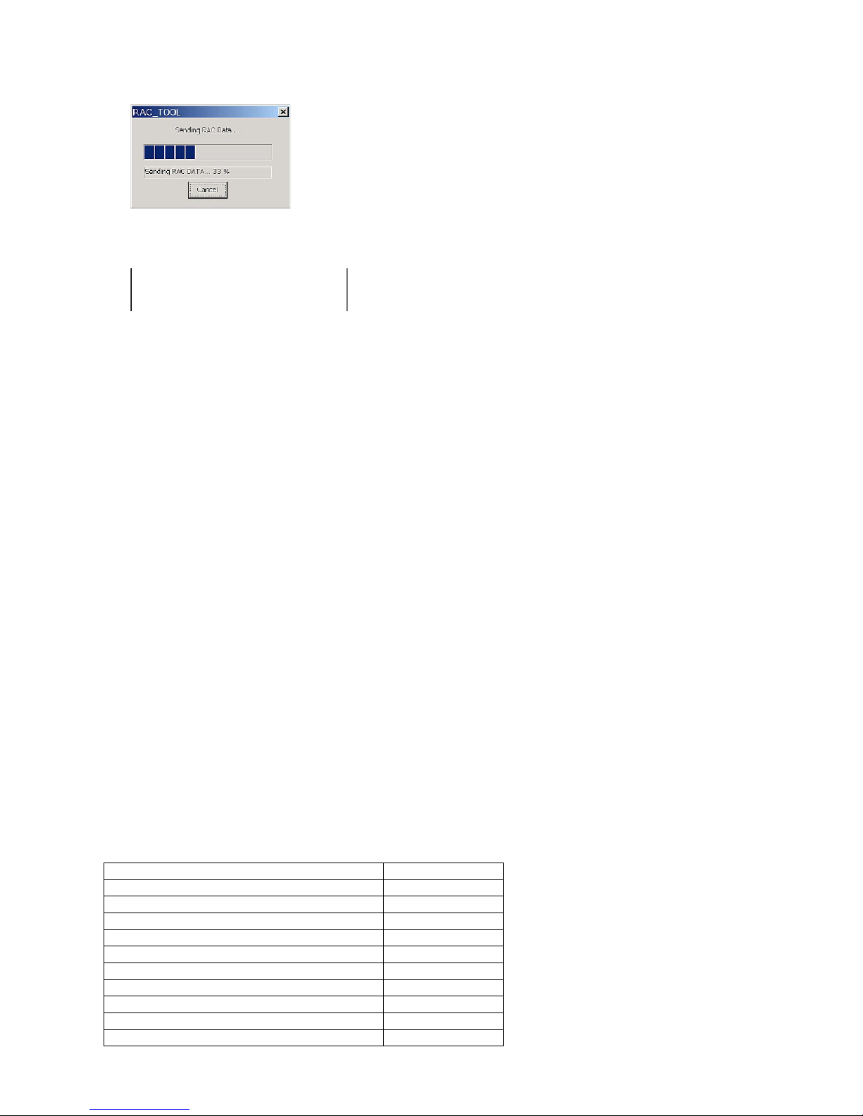
12) The following transmission progress will be shown on the PC.
R A C 9 1 4
R A C I P L O K
E N D 9 1 4
13) The following receipt will be issued when all the data has been received.
(ECR will be terminated automatically if data is not receiving 5 second or more)
This process will take approximately 20 minutes to send IPL data to the RAC-12B.
* Please keep the special RAC memory pack for IPL, otherwise you need to do the above process again.
3-2. Send the IPL data from RAC to ECR.
1) Pull out AC cord from wall outlet.
2) Insert the RAC-12B which has the IPL data to the ECR.
3) Press and hold “Journal” feed key and plug in AC cord to the wall outlet.
4) Wait few second and release Journal feed key.
“BT-INIT” should be displayed on the ECR.
5) Enter 44449999 and press "Sub Total" key, then enter 30 and press "Sub Total" key.
6) Back light will be turned off and start loading IPL data from RAC.
7) When the loading is completed, "INIT 0000000000" will be displayed.
8) Enter 99990000 and press "Sub Total" key, then "DIAG 1" will be displayed.
9) Enter your locale code and press "Sub Total" key, then locale code will be printed.
* Locale code is as follows;
Europe: No need to enter the locale code. Skip 8) - 11), go to 12).
U.S.A. and Canada: 200016
Others: 600016
10) Turn the MODE KEY is “OFF”. Then while holding down the “JFEED” button, turn MODE KEY to “PGM”.
11) Release “JFEED” button, then "INIT 0000000000" will be displayed.
12) Enter your INIT code and press "Sub Total" key, then the information will be printed.
* INIT code is as follows;
Model Name INIT Code
SE-C300 / SE-C2000 17200
SE-S2000 13040
SE-S300 12540
TE-1500 23040
TE-900 22540
TK-950 / TK-1550 27200
PCR-T2100 / PCR-T2200 / PCR-T220S 23000
PCR-T2100L / PCR-T2200L 93000
PCR-T470 / PCR-T480 / PCR-T48S 22500
PCR-T470L / PCR-T480L 92500
— 8 —
Page 11
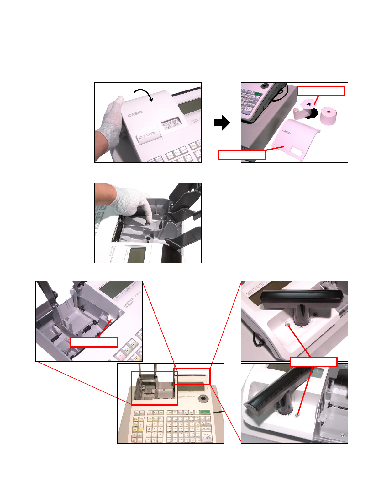
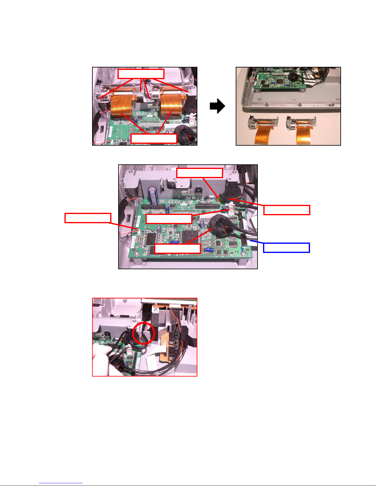
3. DISASSEMBLY
Removing the upper case block
■
1. Remove the Printer cover.
2. Remove two Roll paper and theTake-up reel.
3. Remove the battery cover and disengage the battery.
Take-up reel
Printer cover
4. Remove 3 screws.
Screw
Screws
— 9 —
Page 12
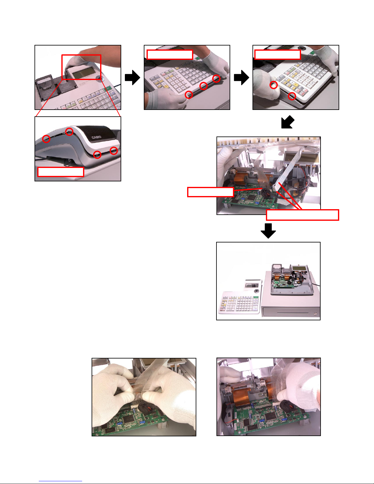
5. Lift the upper case block and then remove 3 FPCs.
Hooks Hooks
Hooks
FPC (KEY)
FPC (Pop-up displasy)
Assembling Point:
Be sure to insert the FPC securely by holding it with both hands or, if holding it with one hand,
holding by its center.
— 10 —
Page 13

■ Upper case block disassembly
(KEY BOARD ASS'Y, MODE SW ASS'Y, POP-UP DISPLAY BLOCK)
1. Remove the FPC.
2. Remove 8 screws and then the KEY BOARD ASS’Y.
Assembling Point:
Secure the FPC (Mode key, Pop-up Display).
FPC
Screws
3. Remove 15 screws and then disassemble the KEY BOARD ASS'Y.
Screws
— 11 —
Page 14

4. Remove the screw and then the MODE SW ASS’Y.
Screw
5. Remove the hook and then remove the STROBE ASSY
Hooks
6. Remove the hook and then remove the STROBE ASSY.
7. Remove two FPCs and then remove the Rear Display Board.
— 12 —
Page 15
■ Lower case block disassembly (Printer unit, MAIN PCB, LCD unit, E292-COM PCB)
1. Remove 4 screws.
2. Remove 2 FPCs and then 2 Printer units.
Screws
FPCs
3. Remove the FPC and 5 connectors.
Drawer
Motor
Battery
Power
LCD
Assembling Point:
Run the power cable and the motor wires through the groove on the case.
COM Port
— 13 —
Page 16
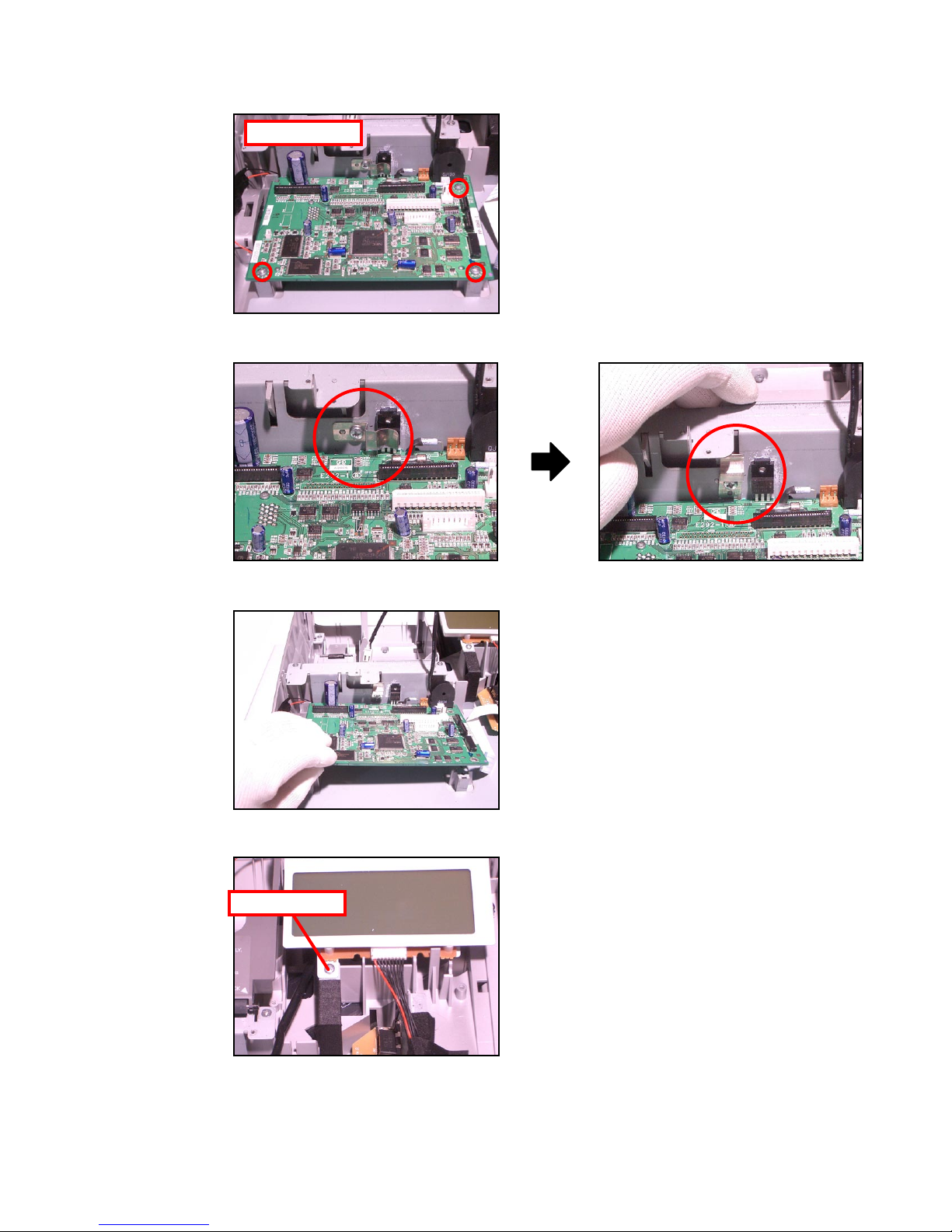
4. Remove 3 screws.
Screws
5. Loosen the screw and change the orientation of the plate.
6. Remove the main PCB.
7. Remove a screw.
Screw
— 14 —
Page 17

8. Remove the hook and then remove the LCD ASSY.
9. Remove 2 screws and then the LCD and E292LCD-E2 PCB.
Screws
10. Unsolder to remove 3 lead wires.
11. Remove the FPC and then the E292LCD-E2 PCB.
Lead wires
FPC
— 15 —
Page 18
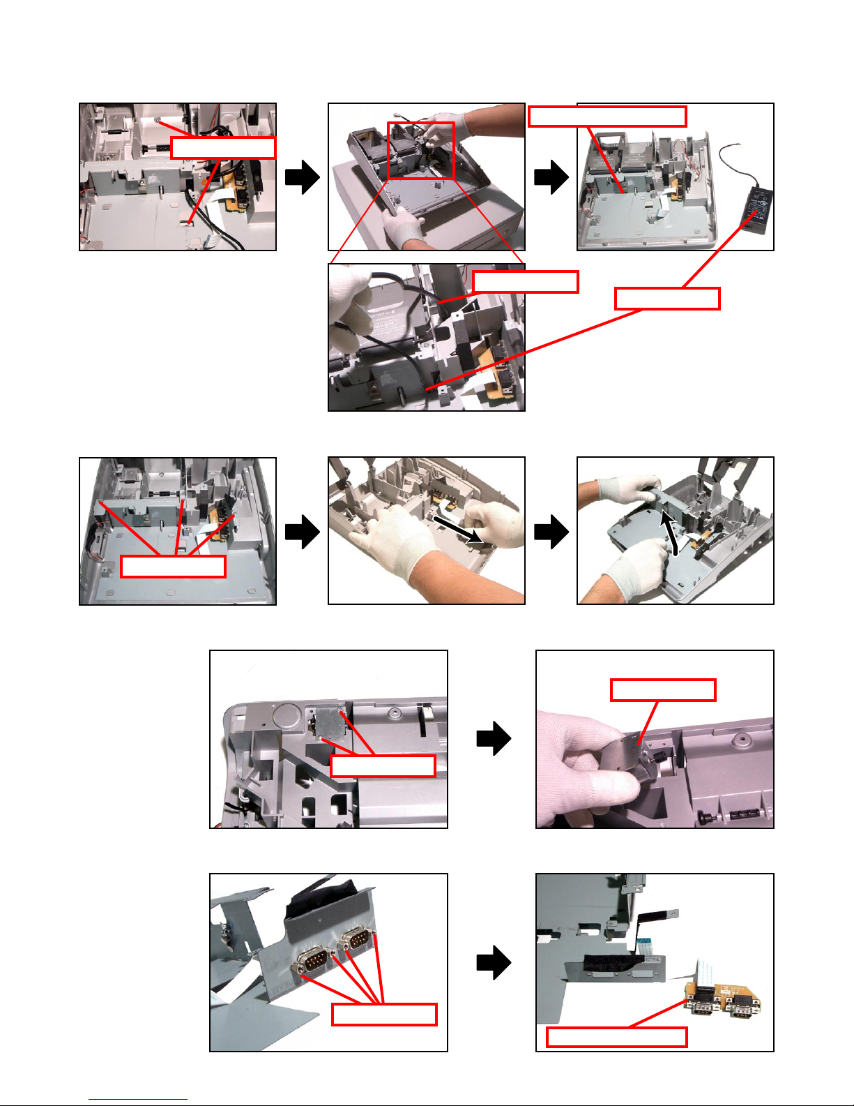
12. Remove 2 screws and then the Lower case unit ans AC Adaptor.
Screws
13. Remove 3 screws and then the Lower case unit ans AC Adaptor.
Lower case unit
Drawer
AC Adaptor
Screws
14. Remove 2 screws and then the Motor assy.
Screws
15. Remove 4 screws and then the E292-COM PCB.
Motor assy
Screws
E292-COM PCB
— 16 —
Page 19
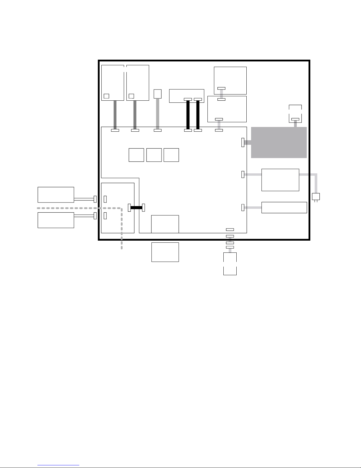
4. BLOCK DIAGRAM
DRAWER UNIT
DRW I/F
RAC12 socket
RAC12
32Mbi
t
PWB : E292-1
PWB : E292-COM
POWER SUPPLY UNIT
AC
cord
AC Adaptor
S01224A
Optional PC or
Optional Hand
Held Scanner
Optional Hand
Held Scanner
+5V supply
+5V suppl
y
COM1
Feed Motor
Feed Motor
PWB:E283-E22
Thermal PRN UNIT
Receipt
Journal
Winder Motor
MODE KEY
PWB:E274-E3
PWB:E292LCD-E2-
1
LCD UNI
T
32Mbit
FROM
CPU
4Mbit
COM2
SRAM
Two AA size alkaline batteries
SE-S300/SE-S2000/TE-900/
TE-1500/PCR series (STROKE KEY)
or
SE-C300/SE-C2000/
TK-950/TK-1550 (COMBINATION KEY)
SE-S2000/SE-C2000/TE-1500/TK-1550/
PCR-T220S/2100/2100L/2200/2200L
— 17 —
Page 20
5. DIAGNOSTIC OPERATION
RPT
AMOUNT
T1 T2 T3 T4
TOTAL CHANGE
INIT
RPT
AMOUNT
T1 T2 T3 T4
TOTAL CHANGE
INIT
,,
B o o t V e r : 4 4 9 9 A
A p l i V e r : 4 5 0 1 A C
AGQA
BAFQA
RPT
AMOUNT
T1 T2 T3 T4
TOTAL CHANGE
DIAG
E S C
5-1. To start the diagnostic program
1. First, be sure that MODE KEY is “OFF”. While holding down the “JFEED” button, turn MODE KEY to “PGM”.
When the “JFEED” button is released, the main display indicates as illustrated below.
2. Enter “99990000” and then press the “SUB TOTAL” button.
3. After DIAG version is printed out, DIAG mode starts.
5-2. Notes for the DIAG
• To perform the continuous check, follow the direction for each test, and input numbers except 0. Input
numbers 1-9 as the command how many times to perform the test for the operation in each page to
perform continuous check. Note that you can only choose one time check or continuous check.
[Others]
• ESC value is printed as follows if the test ended by force. Press the “C” key or turn off the power to end
the test while performing continuous check. The result of ending by force is not printed in each test.
— 18 —
Page 21
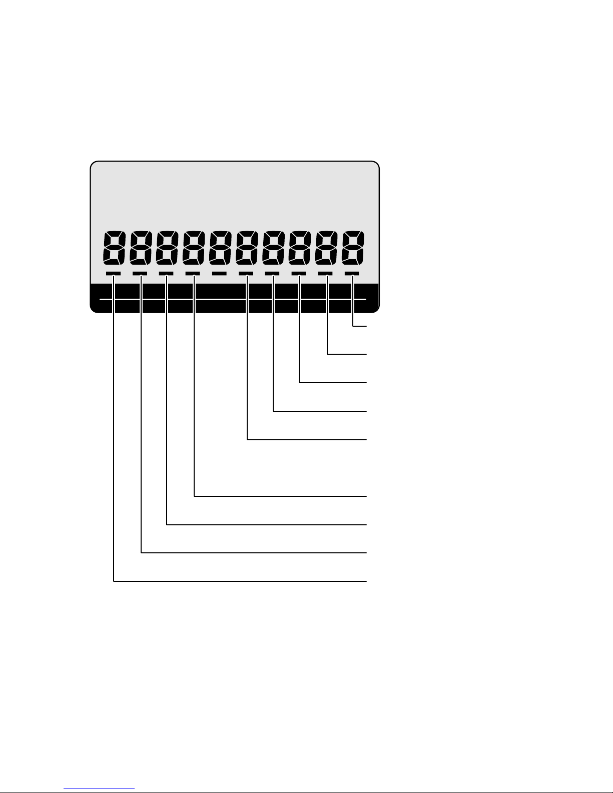
5-3. Displaying the status of the device
RPT
AMOUNT
T1 T2 T3 T4
TOTAL CHANGE
DIAG
Drawer sensor
OFF:Close ON:Open
Printer type
OFF:Reciept ON:Reciept and Journal
KEY type
OFF:Stroke ON:Combination
Memory protection batteris
OFF:Normal ON:Low Battery
Reciept head sensor
OFF:Head down ON:Head up
Journal head sensor
OFF:Head down ON:Head up
Reciept paper sensor
OFF:Paper available ON:No Paper
Journal paper sensor
OFF:Paper available ON:No Paper
RAC detect
OFF:Uninsertion ON:Insertion
[Function]
Changing to status mode or pressing the “C” key when the device is in the command input wait state
during test program startup displays the device status.
[DISPLAY]
The figure below shows the relative display positions for the status information.
— 19 —
Page 22
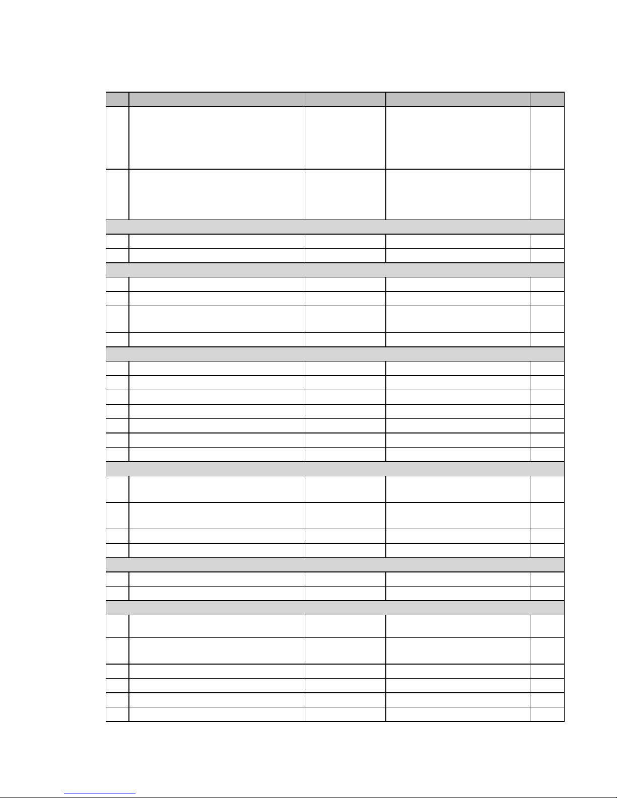
5-4. Check item
The following test can be checked in the diagnostic test.
No Device to be checked Operation Note Page
1 BATCH TEST 1 1 Test Device :
2 BATCH TEST 2 2 Test Device :
RAM TEST
3 RAM WRITE/READ TEST n011 22
4 RAM READ ONLY TEST n111 22
FLASH ROM TEST
5 FLASH ROM CLEAR TEST n212 23
6 FLASH ROM WRITE/READ TEST n012 23
7 FLASH ROM CLEAR & WRITE/READ
TEST
8 FLASH ROM PROECT AREA CLEAR 0216 25
DISPLAY TEST
9 DISPLAY TEST n21 25
10 DISPLAY TEST (REPEAT) 521 26
11 7 SEGMENT DISPLAY TEST 221 26
12 LCD BACKLIGHT TEST c0121 27
13
DISPLAY PATTERN TEST
14
LCD CONTRAST ADJUSTMENT TEST
15
LCD BIT MAP TEST
PRINT TEST
16 INTERNAL PRINTER CHARACTER
PRINT TEST
17 INTERNAL PRINTER GRAPHIC
PATTERN PRINT TEST
18
INTERNAL PRINTER DOT RATE TEST
19 INTERNAL PRINTER PRINT TEST 435 33
RS232C TEST
20 RS232C PORT TEST xn04d 33
21 RS232C PORT BATCH TEST 40 34
TIME/DRAWER/BUZZER/KEY/OBR TEST
22 TIME SETTING
23 TIME DISPLAY 070
24 DRAWER OPEN TEST n091 36
25 BUZZER TEST n092 36
26 KEY DISPLAY TEST 94 37
27 OBR TEST 95 38
RAM READ/WRITE test,
Watch, buzzer test and drawer
open test are performed
continuously.
Display test and LCD
backlight test are performed
continuously.
n312 24
n321 27
421 28
621 29
acn03d 30
P1P1P1P2P2P2n13d
pn33d 32
hhmmss0070
yymmdd0170
170
21
21
31
35
35
— 20 —
Page 23

5-5. Operation of each test
B A T C H 1
R A M W R O
K
B B B B B B B B B B B B B B B B
D A T E 0 5
T I M E 2 3
D R W O
K
E N D 1
03-95:
13/21/
BBBBBBBB
B A T C H 2
D I S P O K
D I S P M A I N O K
D I S P 7 S E G O K
B A C K L I G H T
O K
E N D 2
[ 1 ] BATCH TEST 1
[Function]
RAM READ/WRITE test, Watch, buzzer test and drawer open test are performed continuously.
[Operation]
Operation : 1 SUB TOTAL
The following tests are performed automatically.
(1) RAM test: WRITE/READ area test.
(2) Test print
(3) Time setting: Set the following data.
Arranged data: 2005 December 31,23:59'30
(4) Buzzer: Ring once the one shot buzzer.
No print or display in this test.
(5) Drawer open: Drawer 1 opens only.
(6) Receipt issuance
[Print]
*Test print is also done on the journal side.
*If no journal printers are available, “BBBBBBBBBBBBBBBBBBBBBBBB” is printed out on the receipt.
[ 2 ] BATCH TEST 2
[Function]
Display test and LCD backlight test are performed continuously.
[Operation]
Operation : 2 SUB TOTAL
The following tests are performed automatically.
(1) Display test: Press any key to go to the next screen.
(2) LCD pattern test
(3) 7 segment test
(4) LCD backlight test Press any key to switch ON/OFF.
[Print]
— 21 —
Page 24

[ 3 ] RAM WRITE/READ TEST
R A M 1 1
R A M W R O
K
E N D 1
1
R A M 1 1 1
R A M R D O
K
E N D 1 1 1
[Function]
Data on the RAM is written, and tests are performed to check if the data has been written properly.
The data to be written should be a one-byte data, which is the sum of the fourth, the third, and the
second digits from the last of the address. After writing is completed, the data is read and checked
whether it is identical to the original. The test will not be performed, however, in the area where
performing this test affects the operation. Memory used in HANDLER (static area). Memory used in
DIAG (stack, static areas). Code, however, will be performed from FLASH ROM.
[Operation]
Operation : n 0 1 1 SUB TOTAL
n: 0 = One time check (can be omitted)
not 0 = Continuous check (To stop the test, press “C” key)
[Display]
A counter is displayed in the 7 segments to indicate that RAM check is in progress.
[Print]
The following is printed when all areas for RAM are tested.
[ 4 ] RAM READ ONLY TEST
[Function]
Read only test for RAM (read, write, verify) is performed.
Note that write test (n011) must be performed right before this test.
[Operation]
Operation : n 1 1 1 SUB TOTAL
n: 0 = One time check (can be omitted)
not 0 = Continuous check (To stop the test, press “C” key)
[Display]
A counter is displayed in the 7 segments to indicate that RAM check is in progress.
[Print]
The following is printed when all areas for RAM are tested.
— 22 —
Page 25

[ 5 ] FLASH ROM CLEAR TEST
R O M 2 1 2
F L A S
H C L R O K
E N D 2 1 2
R O M 1 2
F L A S H W R O
K
E N D 1
2
[Function]
After this test, be sure to perform [6] FLASH ROM WRITE/READ test before conducting other tests. If
other tests are performed without having conducted FLASH ROM WRITE/READ test and the program
is damaged, proper operation cannot be guaranteed. Please perform IPL again.
[Operation]
Operation : n 2 1 2 SUB TOTAL
n: 0 = One time check (can be omitted)
not 0 = Continuous check (To stop the test, press “C” key)
[Display]
A counter is displayed in the 7 segments to indicate that RAM check is in progress.
[Print]
The following is printed when all areas for RAM are tested.
[ 6 ] FLASH ROM WRITE/READ TEST
[Function]
[5] FLASH ROM CEAR test must have been performed immediately before this test. The test is
performed in the user area.
[Operation]
Operation : n 0 1 2 SUB TOTAL
n: 0 = One time check (can be omitted)
not 0 = Continuous check (To stop the test, press “C” key)
[Display]
A counter is displayed in the 7 segments to indicate that RAM check is in progress.
[Print]
The following is printed when all areas for RAM are tested.
— 23 —
Page 26

[ 7 ] FLASH ROM CLEAR & WRITE/READ TEST
R O M 3 1 2
F L A S H O
K
E N D 3 1 2
L O C A L E 2 1 6
L O C A L E C L R O
K
E N D 2 1 6
[Function]
After CLEAR function clears the memory, WRITE test is performed.
[Operation]
Operation : n 3 1 2 SUB TOTAL
n: 0 = One time check (can be omitted)
not 0 = Continuous check (To stop the test, press “C” key)
[Display]
A counter is displayed in the 7 segments to indicate that RAM check is in progress.
[Print]
The following is printed when all areas for RAM are tested.
[ 8 ] FLASH ROM PROTECT AREA CLEAR
[Function]
The area with LOCAL/CONTRAST setting is cleared.
[Operation]
Operation : 0 2 1 6 SUB TOTAL
[Print]
— 24 —
Page 27

[ 9 ] DISPLAY TEST
Command input Pattern 1 Pattern 2 END
Press Any key Press Any key
RPT
AMOUNT
T1 T2 T3 T4
TOTAL CHANGE
RPT
AMOUNT
T1 T2 T3 T4
TOTAL CHANGE
Pattern 1 Pattern 2
ABCDEFGHIJKLMOP
QRSTUVWXYZabcdef
D I S P 2 1
D I S P O K
N D 2 1
[Function]
The test of LCD/7 segment display and transaction display is performed as shown below.
[Operation]
Operation : n 2 1 SUB TOTAL
n: 0 = One time check (can be omitted)
not 0 = Continuous check (To stop the test, press “C” key)
[Print]
— 25 —
Page 28

[ 10 ] DISPLAY TEST (REPEAT)
RPT
AMOUNT
T1 T2 T3 T4
TOTALCHANGE
Pattern 1
RPT
AMOUNT
T1 T2 T3 T4
TOTALCHANGE
RPT
AMOUNT
T1 T2 T3 T4
TOTALCHANGE
Pattern 2 Pattern 3
D I S P 5 2 1
D I S P O K
N D 5 2
1
RPT
AMOUNT
T1 T2 T3 T4
TOTALCHANGE
D I S P 2 2 1
D I S P 7 S E G O K
N D 2 2
1
[Function]
The test of LCD/7 segment display and transaction display is performed as shown below.
[Operation]
Operation : 5 2 1 SUB TOTAL
To stop the test, press “C” key
[Print]
[ 11 ] 7 SEGMENT DISPLAY TEST
[Function]
The test of 7 segment display is performed as shown below.
[Operation]
Operation : 2 2 1 SUB TOTAL
To stop the test, press “C” key
[Print]
— 26 —
Page 29

[ 12 ] LCD BACKLIGHT TEST
D I S P 1 2 1
D I S P L I G H T O
K
N D 1 2
1
Command input
Pattern 1 Pattern 4
END
Press Any key Press Any key
RPT
AMOUNT
T1 T2 T3 T4
TOTALCHANGE
Pattern 3
RPT
AMOUNT
T1 T2 T3 T4
TOTALCHANGE
Pattern 1
ABCDEFGHIJKLMOP
QRSTUVWXYZabcdef
RPT
AMOUNT
T1 T2 T3 T4
TOTALCHANGE
Pattern 2
ABCDEFGHIJKLMOP
QRSTUVWXYZabcdef
RPT
AMOUNT
T1 T2 T3 T4
TOTALCHANGE
Pattern 4
D I S P 3 2 1
D I S P M A I N O K
N D 3 2
1
[Function]
LCD Backlight is turned ON/OFF.
[Operation]
Operation : c 0 1 2 1 SUB TOTAL
c: 0 = Press any button to turn “OFF” -> “ON”
1 = Backlight OFF
2 = Backlight ON
[Print]
[ 13 ] DISPLAY PATTERN TEST
[Function]
Performs an LCD display pattern test.
The test displays the 4 patterns shown below.
In run-once mode, press any key to end the test. In unlimited-run mode, set the mode to OFF to end
the test.
[Operation]
Operation : n 3 2 1 SUB TOTAL
n: 0 = One time check (can be omitted)
not 0 = Continuous check (To stop the test, press “C” key)
[Print]
— 27 —
Page 30

[ 14 ] LCD CONTRAST ADJUSTMENT TEST
RPT
AMOUNT
T1 T2 T3 T4
TOTALCHANGE
ABCDEFGHIJKLMOP
QRSTUVWXYZabcdef
D I S P 4 2 1
L C D C O N T R A S T E S C
E N D 4 2 1
L C D C O N T R A S T N G
L C D C O N T R A S T O V R
L C D C O N T R A S T E S C
[Function]
Adjusts the LCD contrast and writes the adjustment to the FLASH ROM.
Up to 16 adjustments can be written to the FLASH ROM. If more than 16 adjustments are written, an
error occurs.
The contrast value when adjustment begins is the value written during the previous adjustment ("22" if
no data has been written). After the adjustment, pressing the “#1” key updates the stored adjustment
value.
[Operation]
Operation : 4 2 1 SUB TOTAL
“RECEIPT ON/OFF” button: Current contrast + 1 (dark)
“PRICE” button: Current contrast - 1 (light)
“#1” button: Confirm contrast (writes the value to FLASH ROM). Exits the adjustment sequence.
To stop the test, press “C” key.
[DISPLAY]
[Print]
XX is the adjustment value.
Printed when an error occurs.
Printed if more than 16 adjustments have been written.
Printed if you exited the sequence without setting an adjustment value.
[Operation]
Up to 16 adjustments can be written to the FLASH. If more than 16 adjustments are written, an error
occurs. In such cases, perform the following command to clear the area.
Operation : 1 0 4 2 1 SUB TOTAL
— 28 —
Page 31

[ 15 ] LCD BIT MAP TEST
Command input Pattern 1 Pattern 4 END
Press Any key Press Any key
RPT
AMOUNT
T1 T2 T3 T4
TOTALCHANGE
Pattern 3
RPT
AMOUNT
T1 T2 T3 T4
TOTALCHANGE
Pattern 1
RPT
AMOUNT
T1 T2 T3 T4
TOTALCHANGE
Pattern 2
RPT
AMOUNT
T1 T2 T3 T4
TOTALCHANGE
Pattern 4
D I S P 6 2 1
L C D B I T M A P O
K
N D 6 2
1
[Function]
Performs an LCD display pattern test.
[Operation]
Operation : 6 2 1 SUB TOTAL
To stop the test, press “C” key.
[Print]
— 29 —
Page 32

[ 16 ] INTERNAL PRINTER CHARACTER PRINT TEST
B B B B B B B B B B B B B B B B
[FUNCTION]
This test will check the characters in the receipt/journal of the internal printer.
[Operation]
Operation : a c n 0 3 d SUB TOTAL
a: 0 = normal print out
1 = reduced size print out
c : 0 = prints character’ B’
1 = prints all characters
n : 0 = One time check
not 0 = Continuous check (To stop the test, press “C” key)
d : 3 = Recipet
4 = Journal
5 = Recipet and Journal
[Print]
1. Prints character’ B’
2. Prints all characters
Refer to the figure in the next page for the characters to be printed.
The printing order is in the order of the character code. The characters from 0x20(SP) to 0xFD(•) are
printed.
A space is printed for a code without the printing character.
A character which cannot be printed is a character within the range of the code 0x00 to 0x1F and
0xFB to 0xFF.
— 30 —
Page 33

[ 17 ] INTERNAL PRINTER GRAPHIC PATTERN PRINT TEST
Print pattern image
Print pattern image
Print pattern image
[FUNCTION]
This test will check the graphic patterns in the receipt/journal of the internal printer.
The graphic patterns and the print images are as follows;
Graphic pattern 1
Graphic pattern 2
Graphic pattern 1
Graphic pattern 2
:
: repeat (for 28 Dot line )
[Operation]
Operation : P1 P1 P1 P2 P2 P2 n 1 3 d SUB TOTAL
P1: 0 = Graphic patter 1 (change 8 bit into a decimal number and input it)
P2: 0 = Graphic patter 2 (change 8 bit into a decimal number and input it)
n: 0 = One time check
not 0 = Continuous check (To stop the test, press “C” key)
d : 3 = Recipet
4 = Journal
5 = Recipet and Journal
* Print patterns and commands
(1) Receipt, 25% pattern, continuous
Operation : 0 8 5 0 0 0 1 1 3 3 SUB TOTAL
The display unit of the print pattern image in the right is as follows;
Horizontal: dot
Vertical: do line
(2) Receipt, 50% pattern, continuous
Operation : 0 8 5 1 7 0 1 1 3 3 SUB TOTAL
The display unit of the print pattern image in the right is as follows;
Horizontal: dot
Vertical: do line
(3) Receipt, 100% pattern, continuous
Operation : 2 5 5 2 5 5 1 1 3 3 SUB TOTAL
The display unit of the print pattern image in the right is as follows;
Horizontal : dot
Vertical : do line
— 31 —
Page 34

[ 18 ] INTERNAL PRINTER DOT RATE TEST
(1) 3 dot lines
The first 3 dot lines in the 1/2 line ( 14 dot lines) out of one line are printed in all dots.
3 dot lines (printed in all dots)
11
dot lines (no printing)
3 dot lines (printed in all dots)
11
dot lines (no printing)
(2) 5 dot lines
The first 5 dot lines in the 1/2 line ( 14 dot lines) out of one line are printed in all dots.
5 dot lines (printed in all dots)
9 dot lines (no printing)
5 dot lines (printed in all dots)
9 dot lines (no printing)
(3) 7 dot lines
The first 7 dot lines in the 1/2 line ( 14 dot lines) out of one line are printed in all dots.
7 dot lines (printed in all dots)
7 dot lines (no printing)
7 dot lines (printed in all dots)
7 dot lines (no printing)
Printing image of 1/2 line
(14 dot lines)
Printing image of 1/2 line
(14 dot lines)
printing image of 1 line
(28 dot lines)
Printing image of 1/2 line
(14 dot lines)
Printing image of 1/2 line
(14 dot lines)
printing image of 1 line
(28 dot lines)
Printing image of 1/2 line
(14 dot lines)
Printing image of 1/2 line
(14 dot lines)
printing image of 1 line
(28 dot lines)
[FUNCTION]
This test will check the printing of the receipt/journal according to the following specifications.
The printing specification is reflected in 1/2 line and the only specified number of dot lines are printed
in all dots from the 1 dot line.
Note that 1/2 line is printed two times because the printing unit is one line.
[Operation]
Operation : p n 3 3 d SUB TOTAL
p: 0= 3 dot line
1 = 5 dot line
2 = 7 dot line
n: 0 = One time check
not 0 = Continuous check (To stop the test, press “C” key)
d : 3 = Recipet
4 = Journal
5 = Recipet and Journal
[Print]
— 32 —
Page 35

[ 19 ] INTERNAL PRINTER PRINT TEST
P R T 4 3 5
N D 4 3
5
COM1 30041
RTS1=1 --> CTS1=1 OK
DTR1=1 --> DSR1=1 OK
RTS1=0 --> CTS1=0 OK
DTR1=0 --> DSR1=0 OK
TxD --> RxD OK
END 30041
[FUNCTION]
Print out is performed on the internal printer receipt/journal in the following format. This test is
performed once. The number of the tests to be performed cannot be changed.
[Operation]
Operation : 4 3 5 SUB TOTAL
[Print]
Prints 3 lines from character code 0X30 to 0X8.
[ 20 ] RS232C PORT TEST
[FUNCTION]
This is the RS232C test.
The loop back test for RS232C port is performed by making the connection shown in the figure.
Refer to [ 22 ] RS232C PORT BATCH TEST the figure for RS232C port connection.
[Operation]
Operation : x n 0 4 d SUB TOTAL
x: Baud rate selection
0=2400 bps, 1=4800 bps, 2=9600 bps, 3=19.2 kbps, 4=38.4 kbps, 5=56 kbps, 6=Invalid, 7=115.2
kbps
n: 0 = One time check (can be omitted)
not 0 = Continuous check (To stop the test, press “C” key)
d: 1 = COM1 (UART1)
2 = COM2 (UART0)
[Print]
— 33 —
Page 36

[ 21 ] RS232C PORT BATCH TEST
COM BATCH
Figure : RS232C port connection
outputs "1" R "0" from the output terminal and checks the input terminal.
TxD
RxD
RTS
CTS
DTR
DSR
COM1/2
COM BATCH 40
RTS1=1 --> CTS1=1 OK
DTR1=1 --> DSR1=1 OK
RTS1=0 --> CTS1=0 OK
DTR1=0 --> DSR1=0 OK
TxD --> RxD OK
RTS2=1 --> CTS2=1 OK
RTS2=0 --> CTS2=0 OK
DTR2=0 --> DSR2=0 OK
TxD --> RxD OK
END 40
COM1
COM2
[Function]
This is the RS232C port batch test.
When performing this test, fix loop back connectors to all COM ports.
By the setting below, the loop back batch test is performed once from COM1 through COM2.
[Operation]
Operation : 4 0 SUB TOTAL
Baud rate: COM1: 19.2 kbps, COM 2: 9600 bps
Check time: one time
[Print]
— 34 —
Page 37

[ 22 ] TIME SETTING
RPT
AMOUNT
T1 T2 T3 T4
TOTAL CHANGE
06/01/01
05-49 ss
[ 23 ] TIME DISPLAY
[Function]
This sets the time and date.
When setting the time, the time and date will be displayed without inputting the fixed value.
[Operation]
(1) Date and time setting
Operation : h h m m s s 0 0 7 0 SUB TOTAL
hh: hour
mm: minutes
ss: second
Operation : y y m m d d 0 1 7 0 SUB TOTAL
yy: year
mm: month
dd: day
(2) Date and time display
Operation (time): 0 7 0 SUB TOTAL
Operation (date): 1 7 0 SUB TOTAL
Pressing
“C” key
displays the date and time in order. Pressing
the test.
[LCD]
“C” key
while the time is displayed ends
— 35 —
Page 38

[ 24 ] DRAWER OPEN TEST
D R W 9 1
D R W O
K
E N D 9
1
B U Z Z 9 2
E N D 9
2
[Function]
This test checks whether the drawer opens or not..
[Operation]
Operation : n 0 9 1 SUB TOTAL
n: 0 = One time check
not 0 = Continuous check (To stop the test, press “C” key)
[Print]
[ 25 ] BUZZER TEST
[FUNCTION]
This test checks whether the buzzer sounds or not.
One time check causes one shot buzzer to sound once, while infinite time check causes the buzzer to
sound for 500 msec. When the infinite time check is performed, press “C” key to stop the intermittent
buzzer.
[Operation]
Operation : n 0 9 2 SUB TOTAL
n: 0 = One time check
not 0 = Continuous check (To stop the test, press “C” key)
[Print]
— 36 —
Page 39

[ 26 ] KEY DISPLAY TEST
089 082
087
088 081
086
085 078
084
C
079
076 073 070
075 072 069
007 008 009
004 005 006
001 002 003
000 011 012
067 060 053
066 059 052
065 058 051
064 057 050
063 056 049
062 055
024 018
023 015
046 039 032
025
045 038
044 037
043 036
042 035
041 034048
014
013
089 082
087
088 081
086
085 078
084
C
079
076 073 070
075 072 069
007 008 009
004 005 006
001 002 003
000 011 012
067 060 053
066 059 052
065 058 051
064 057 050
063 056 049
062 055
024 018
023 015
046 039 032
025
045 038
044 037
043 036
042 035
041 034
031
030
029
028
027048
014
013
C 037 034
007 008 009
004 005 006
001 002 003
000 011 012
031 024 019
030 023 018
041 039 036
040 038 035
033 026 021
049
032 025 020
029 022 015
028 014=017
027 013
113
11
2
057
048 056
065 073
064 072
081 089
080 088
097 105
096 104
047 111
11
0
055
046 054
063 071
062 070
079 087
078 086
095 103
094 102
045 109
108
053
044 052
061 069
060 068
077 085
076 084
093 101
092 100
043 107
106
051
042 050
059 067
058 066
075 083
074 082
091 099
090 098
RPT
AMOUNT
T1 T2 T3 T4
TOTALCHANGE
11:STROKE KEY
10:COMBI KEY
KEY CODE
[FUNCTION]
The hard key code of a key is displayed every time any key except “C” key is pressed.
The hard key code is arranged as follows.
[Operation] [LCD]
Operation : 9 4 SUB TOTAL
To stop the test, press “C” ke
[Location of the key code]
STROKE KEY (SE-S300/SE-S2000)
STROKE KEY (SE-S300/SE-S2000)
COMBI KEY (SC-S300/SE-C2000)
— 37 —
Page 40

[ 27 ] OBR TEST
O B R 9 5
O B R O
K
O
E N D 9 5
B R E R R * * * * * * * *
[Function]
This is a scanner test. The test enters the wait mode for the scanner input, and waits only for scanner.
The test determines the result between OK and NG by comparing the fixed data and the read data.
* The fixed barcode is as follows.
[Operation]
SE-S2000/SE-C2000: COM2
SE-S300/SE-C300: COM1
Operation : 9 5 CA/AMT TEND
To stop the test, press “C” key
[Print]
When an error occurs, the read data is printed.
— 38 —
Page 41

6. ERROR CODE LIST
This section describes what to do when you have problems with operation.
When an error occurs
Errors are indicated by an error codes. When this happens, you can usually find out what the problem is
as illustrated below.
Press C and check the appropriate section of this manual for the operation you want to perform.
Error
code
E001 Wrong mode Mode switch position changed before
E003 Wrong operator The signed on clerk differs from the
E004 Error INIT/FC Initialization or unit lock clear
E008 Please sign on Registration without entering a clerk
E010 Close the drawer The drawer is left open longer than the
E011 Close the drawer Attempt to register while the cash
E016 Change back to REG
E017 Enter CHK/TBL
E018 Enter Table number Attempt made to register an item
E019 Enter number of
E021 No DEPT Link No department linked PLU is
E026 Enter condiment/
E029 In the tender opera-
E031 Press ST key Finalization of a transaction attempted
E033 Enter tendered amount Finalize operation attempted without
E035 Change amount
E036 Remove money from
E037 Digit or amount
E038 Perform money
Message Meaning Action
finalization.
clerk performed the tracking check
registration.
operation in progress.
number.
program time (drawer open alarm).
drawer is open.
Two consecutive transactions
mode
number
customers
preparation PLU
tion
exceeds limit
the drawer
limitation over
declaration
attempted in the refund mode.
Attempt made to register an item
without inputting a check number.
without inputting a table number.
Finalize operation attempted without
entering the number of customer.
registered.
No condiment/preparation PLU is
registered.
Item registration is prohibited, while
partial tender.
without confirming the subtotal.
entering amount tender.
Change amount exceeds preset limit. Input amount tendered again.
Contents of the drawer exceed
programmed limit.
High amount lock out/low digit lock out
error
Read/reset operation without declaring
cash in drawer.
This error appears only when this
function is activated.
Return the mode switch to its original
setting and finalize the operation.
Input correct check number or assign
the proper clerk number.
Complete operation.
Enter a clerk number.
Close the drawer.
Shut the cash drawer.
Switch to another mode and then
back to the RF mode for the next
transaction.
Input a check number.
Input a table number.
Enter the number of customer.
Correct the program.
Register condiment/preparation PLU.
Finalize the transaction.
Press <SUBTOTAL>.
Enter the amount tendered.
Perform paidout operation.
Enter correct amount.
Perform money declaration.
— 39 —
Page 42

Error
code
E040 Issue guest receipt Attempt to register a new transaction
Message Meaning Action
Issue a guest receipt.
without issuing a guest receipt.
E046 REG buffer full Registration buffer full. Finalize the transaction.
E049 CHECK memory full Check tracking index memory full. Finalize and close the check number
currently used.
E050 DETAIL memory full Check tracking detail memory full. Finalize and close the check number
currently used.
E051 CHK/TBL No. is occu-
pied
E053 CHK/TBL No. is not
opened
Attempt to made use <New Check>
to open a new check using a number
that is already used for an existing
check in check tracking memory.
Attempt made to use <Old Check>
reopen a new check using a number
that is not used for an existing check
in check tracking memory.
Finalize and close the check that is
currently under the number that you
want to use or use a different check
number.
Use the correct check number (if you
want to reopen a check that already
exists in check tracking memory) or
use <New Check> to open a new
check.
E075 Negative balance
cannot be finalized
E101 PLU maintenance file
full. Press <#2> to exit
E103 PLU Code is not exist.
Attempt to finalize a transaction when
balance is less than or equal to zero.
Scanning PLU direct maintenance/
Register item(s) until the balance
becomes positive amount.
Terminate the maintenance.
batch maintenance file becomes full.
PLU code is not existed in the file. Enter proper PLU code.
Input the PLU Code
E105 PLU file full Scanning PLU file full Modify the designated item.
E106 Item exists in the PLU
FILE
E112 Close the journal
The designated item has already
existed in the scanning PLU file.
The journal platen arm is opened. Close the journal platen arm.
platen arm
E114 Close the receipt
The receipt platen arm is opened. Close the receipt platen arm.
platen arm
E139 Negative balance is
not allowed
Attempt to register <–> or <CPN>
when the balance becomes negative.
Enter proper minus/coupon amount.
E146 Arrangement file full Arrangement file is full. Set the arrangement properly.
E200 Insert RAC RAC is set. Set RAC.
E201 Illegal Format Illegally formatted RAC Format the RAC.
E202 File not found The designated file is not found in the
Enter proper file name.
RAC.
E205 File already exist. Can not write, because designated file
Check the operation and retry.
has already been in the RAC.
— 40 —
Page 43

7. PCB LAYOUT
MAIN PCB (E292-1 PCB)
(TOP VIEW)
— 41 —
Page 44

MAIN PCB (E292-1 PCB)
(BOTTOM VIEW)
— 42 —
Page 45

8. CIRCUIT DIAGRAMS
SE-S300/SE-S2000/SE-C300/SE-C2000
PCR-T48S/PCR-T470/PCR-T480/PCR-T470L/PCR-T480L
PCR-T220S/PCR-T2100/PCR-T2200/PCR-T2100L/PCR-T2200L
1. MAIN PCB CIRCUIT
1-1. MAIN PCB CIRCUIT 1/5 (PW,PWD,COM) ........................................................................44
1-2. MAIN PCB CIRCUIT 2/5 (CPU) .........................................................................................45
1-3. MAIN PCB CIRCUIT 3/5 (ROM,RAM,SIO) ........................................................................46
1-2. MAIN PCB CIRCUIT 4/5 (LCD,KEY,LED) .......................................................................... 47
1-3. MAIN PCB CIRCUIT 5/5 (PRT) ..........................................................................................48
SE series
TE series / TK series
TE-900/TE-1500/TK-950/TK-1550
PCR series
(EX-292/EX-293/EX-592/EX-593)
2. COM PCB CIRCUIT ...................................................................................................................49
3. DISPLAY PCB CIRCUIT ............................................................................................................50
4. REAR DISPLAY PCB CIRCUIT .................................................................................................51
— 43 —
Page 46

— 44 —
E292-1
Model
NameBoard No. Drawing No.
MAIN BOARD 1/5 (PW, PWD, COM)
RJE502513D201CASIO COMPUTER CO.,LTD. SE-S300/S2000/C300/C2000
SE-S300 and SE-C300: not used
SE-S300: not used
Page 47

— 45 —
SW1, R234, C112: not used
E292-1
Model
NameBoard No. Drawing No.
MAIN BOARD 2/5 (CPU)
RJE502513D201CASIO COMPUTER CO.,LTD. SE-S300/S2000/C300/C2000
Page 48

— 46 —
E292-1
Model
NameBoard No. Drawing No.
MAIN BOARD 3/5 (ROM, RAM, SIO)
RJE502513D201CASIO COMPUTER CO.,LTD. SE-S300/S2000/C300/C2000
R233: not used
Page 49

— 47 —
E292-1
Model
NameBoard No. Drawing No.
MAIN BOARD 4/5 (LCD, KEY, LED)
RJE502513D201CASIO COMPUTER CO.,LTD. SE-S300/S2000/C300/C2000
Page 50

— 48 —
E292-1
Model
NameBoard No. Drawing No.
MAIN BOARD 5/5 (PRT)
RJE502513D201CASIO COMPUTER CO.,LTD. SE-S300/S2000/C300/C2000
R219,220,221,222:SE-S2000 not used
SE-S300: not used
SE-S300: not used
IC22,C75,R184:SE-S300 not used
SE-S300: not used
SE-S300: not used
R223,224,225,226,227,228:SE-S2000 not used
R173:SE-S300 not used
SE-S300/C300 only
SE-S2000: not used
SE-S2000/C2000 only
SE-S300: not used
Page 51

— 49 —
E283-E22
Model
NameBoard No. Drawing No.
CON BOARDCASIO COMPUTER CO.,LTD. SE-S300/S2000/C300/C2000
SE-S2000/SE-C2000 only
Page 52

— 50 —
E292LCD-E2-1 A
Model
NameBoard No. Drawing No.
DISPLAY-BOARD RJE******D302CASIO COMPUTER CO.,LTD. SE-S300/S2000/C300/C2000
VCC
VCC
V3.0
V3.0
V3.0
VCC
VCC
-9.5V
VLCD
D1
RB161M-20TRD1RB161M-20TR
VSS
1
VIN2VO
3
NC
4
IC2
S-817A30ANB
IC2
S-817A30ANB
R1410K R1410K
J7 0J7 0
J10 0J10 0
TP16TP16
TP7TP7
VR
1
V5
2
V4
3
V3
4
V2
5
V1
6
VOUT
7
NC1
8
VSS
9
NC2
10
VDD
11
SI
12
SCL
13
A0
14
/RESET
15
/CS1B
16
CN2
IMSA-9632S-16Y917
CN2
IMSA-9632S-16Y917
*2 0*2 0
C510u C510u
TP12TP12
R3510K R3510K
C21uC2
1u
J3 0J3 0
C230.1u C230.1u
R6 2MFR6 2MF
C14100p C14100p
1A
1
1B
2
1Y
3
2A
4
2B
5
2Y
6
3A
9
3B
10
3Y
8
4A
12
4B
13
4Y
11
GND7VCC
14
IC3
SN74LV08APWR
IC3
SN74LV08APWR
R51MF R51MF
J9 0J9 0
R7 1.5MFR7 1.5MF
J2 0J2 0
1 2
L1
CDRH3D16NP-220NC
L1
CDRH3D16NP-220NC
C30
0.022u
C30
0.022u
C28
22p
C28
22p
TP8TP8
*3 0*3 0
C29
0.1u
C29
0.1u
R1210K R1210K
TP11TP11
C12100p C12100p
R1010K R1010K
R1310K R1310K
R111K R111K
D2 RB751V-40D2 RB751V-40
C3
10uC310u
R21 300R21 300
R1
68.1K
F
R1
68.1K
F
TP24TP24
PA-GPA-G
TP15TP15
C250.1u C250.1u
TP4TP4
2
13
Q1
DTA115EUAQ1DTA115EUA
TP2TP2
J60 J60
J1 0J1 0
*4 0*4 0
TP9TP9
R16 300R16 300
R18 300R18 300
C101uC10
1u
R4510K R4510K
R15 300R15 300
R17 300R17 300
R2
9.09K
F
R2
9.09K
F
C21 0.1uC21 0.1u
PA-WPA-W
TP17TP17
C15100p C15100p
TP23TP23
2
31
Q2
DTD113ZKQ2DTD113ZK
TP18TP18
J8 0J8 0
*5 0*5 0
SW
1
GND
2
FB
3
SDREF
4
D
5
Vin
6
IC1
LT3462A
IC1
LT3462A
C26
33u/10V
C26
33u/10V
TP10TP10
C91u C91u
TP22TP22
C81u C81u
R8 510KR8 510K
C71u C71u
R24 300R24 300
GND1
1
RESET
2
VCC
3
/CS_1B
4
AD
5
/LED_ON
6
S_DATA
7
S_CLK
8
GND2
9
CN3
A2001WR2-9P
CN3
A2001WR2-9P
A_White
1
A_Geen
2
NC
3
Cathode
4
CN1
BM04B-SRSS
CN1
BM04B-SRSS
C19100p C19100p
C13100p C13100p
TP3TP3
OUT4IN B
1
IN A
2
GND3Vcc
5
IC4
SN74LVC1G08DCKR
IC4
SN74LVC1G08DCKR
C18100p C18100p
TP5TP5
R22 300R22 300
R20 300R20 300
C20100p C20100p
J5 0J5 0
C17100p C17100p
C24 0.1uC24 0.1u
C61u C61u
TP14TP14
TP19TP19
PA-BPA-B
C1 1uC1 1u
R9 510KR9 510K
C16100p C16100p
*1 0*1 0
TP6TP6
C22
100u/10V
C22
100u/10V
C11100p C11100p
TP21TP21
R19 300R19 300R23 300R23 300
J4 0J4 0
TP20TP20
C4
33u/10VC433u/10V
TP13TP13
Page 53

— 51 —
E283-E22
Model
NameBoard No. Drawing No.
REAR-DISPLAY-BOARD RJE502391D307CASIO COMPUTER CO.,LTD. SE-S300/S2000/C300/C2000
HDSP-521G
D4
HDSP-521G
D3
f1
b2
a2
f2
DI2
DI1
b1a1g1
e1
DP2c2g2d2e2
DP1c1d1
181716151413121110
123456789
f1
b2
a2
f2
DI2
DI1
b1a1g1
e1
DP2c2g2d2e2
DP1c1d1
181716151413121110
123456789
HDSP-521G
D2
f1
b2
a2
f2
DI2
DI1
b1a1g1
e1
DP2c2g2d2e2
DP1c1d1
181716151413121110
123456789
HDSP-521G
D1
f1
b2
a2
f2
DI2
DI1
b1a1g1
e1
DP2c2g2d2e2
DP1c1d1
181716151413121110
123456789
DG3
DG2
SB1
SF1
SA1
SD1
SE1
SC1
SG1
DG3
DG2
SB1
SF1
SA1
SD1
SE1
SC1
SG1
1
2
3
4
5
6
7
8
9
CN1
IMSA-9610S-09B-TC
SDP1
SB0
SF0
SA0
SC0
SD0
SDP0
SE0
SG0
DG0
DG1
STR
SDP1
SB0
SF0
SA0
SC0
SD0
SDP0
SE0
SG0
DG0
DG1
STR
1
2
3
4
5
6
7
8
9
10
11
12
CN2
IMSA-9610S-12B-TC
DG0
DG1
D6D7HLMP-S501
HLMP-S501
Page 54

9. PARTS LIST
SE series
SE-S300/SE-S2000/SE-C300/SE-C2000
TE series / TK series
TE-900/TE-1500/TK-950/TK-1550
PCR series
PCR-T48S/PCR-T470/PCR-T480/PCR-T470L/PCR-T480L
PCR-T220S/PCR-T2100/PCR-T2200/PCR-T2100L/PCR-T2200L
(EX-292/EX-293/EX-592/EX-593)
EXPLODED VIEW
BODY ............................................................................................................53
BUTTON BLOCK (STROKE) ........................................................................54
BUTTON BLOCK (COMBINATION) .............................................................55
PARTS LIST
SE series ...........................................................................................................56
SE-S300/SE-S2000/SE-C300/SE-C2000
TE series / TK series .........................................................................................60
TE-900/TE-1500/TK-950/TK-1550
PCR series ........................................................................................................64
PCR-T48S/PCR-T470/PCR-T480/PCR-T470L/PCR-T480L
PCR-T220S/PCR-T2100/PCR-T2200/PCR-T2100L/PCR-T2200L
DRAWER
DRAWER S type .............................................................................................68
DL-1331/DL-1332/DL-1842
DRAWER M type ............................................................................................70
NOTES :
1. Price and specifications are subject to change withput prior notice.
2.
As for spare parts order and supply, refer to the “GUIDEBOOK for Spare Parts Supply”, published separately.
3. The numbers in item column corespond to the same numbers in drawing.
4. CASIO does not supply the spare parts without parts code.
5. Remarks
Q'ty: Quantity used per unit
RANK: A = Essential
B = Stock recommended
C = Less recommended
X = No stock recommended
DL-2800/DL-2801/DL-2802/DL-2803/DL-2804/DL-2805/DL-2806/DL-2807/DL-2432/DL-2433
— 52 —
Page 55

EXPLODED VIEW (BODY)
1
77
2
84
76
84
76
3
4
63
99
90
78
74
73
75
81
82
80
85
89
91
86
83
88
79
87
69
70
72
98
64
65
66
5
6 7
8
67
71
91
91
94
96
93
95
92
92
91
94
92
68
68
101
102
103
100
SE-S2000/SE-C2000/TE-1500/TK-1550/
PCR-T220S/2100/2100L/2200/2200L
SE-S300/SE-C300/
TE-900/TK-950/
PCR-T48S/470/470L/480/480L
— 53 —
Page 56

BUTTON BLOCK (STROKE) SE-S300/SE-S2000/TE-900/TE-1500/PCR series
9
24
23
22
10 21to
28
29
30
27
34
33
32
31
26
25
— 54 —
Page 57

BUTTON BLOCK (COMBINATION) SE-C300/SE-C2000/TK-950/TK-1550
35
52
54
59
4736
~
4736
~
48
48
50
49
51
53
55
57
56
58 58
60
61
62
— 55 —
Page 58

1 SE-S300
1 2 3 4
1.MAIN PCB BLOCK
1 10306296 PCB ASSY/E292-1 TK-RJE502623*001 1 1 A
1 10306297 PCB ASSY/E292-1 TK-RJE502623*002 1 1 A
C5,C29,C45,C48,
C60,C61,C103
10216488 AL CAPACITOR RE3-16V101ME3# 7 7 7 7 A
IC11 10003984 IC/MOS SN74LV00APWR 1 1 1 1 A
IC12,IC16 10005659 IC/MOS SN74LV08APWR 2 2 2 2 A
IC3 10007179 IC/MOS SN74LV10APWR 1 1 1 1 A
IC9,IC10 10275578 IC/MOS SN74LVC374APWR 2 2 2 2 A
IC30 10100704 IC/MOS SN74LVC2G04DCKR 1 1 1 1 A
D2,D4 10157825 DIODE RB520G-30T2R 2 2 2 2 A
Q2 10028955 FET 2SK3018T106 1 1 1 1 A
IC17 10116986 IC SN74AHCT1G08DCKR 1 1 1 1 A
IC23 10214145 IC BA2903F-E2 1 1 A
IC22,IC23 10214145 IC BA2903F-E2 2 2 A
IC2 10241776 IC BA50BC0T 1 1 1 1 A
IC25 10278149 IC BD7050EFV-E2 1 1 A
IC24,IC25 10278149 IC BD7050EFV-E2 2 2 A
IC6 10295605 IC MAX3243ECPWR 1 1 A
IC5,IC6 10295605 IC MAX3243ECPWR 2 2 A
IC18 10275575 IC RV5C348A-E2-FB 1 1 1 1 A
IC13 10132445 IC SN74LVC1G00DCKR 1 1 1 1 A
IC29 10184975 IC SN74LVC2G74DCUR 1 1 1 1 A
IC21,IC26,IC27 10005721 IC SN74LV244APWR 3 3 A
IC1 10251631 IC XC6108N10AMR 1 1 1 1 A
IC7 10275826 IC XC61CN2402MR 1 1 1 1 A
IC4 10275573 IC XC6215B332MR 1 1 1 1 A
IC15 10256784 LSI CY62146EV30LL45ZST 1 1 1 1 A
IC14 10194558 LSI S29JL032H70TFI020 1 1 1 1 A
IC8 10299661 LSI UPD70F3733GJUENABB 1 1 1 1 A
D1,D5,D7-D22 10009218 DIODE 1SS400TE61 18 18 18 18 B
Q5 10275630 MOSFET/CHIP RTF010P02TL 1 1 1 1 B
Q13 10275631 MOSFET/CHIP RTF025N03TL 1 1 1 1 B
D6,D23 23902058 DIODE/CHIP 1SR154-400TE25 2 2 2 2 B
D3 10275792 DIODE/CHIP RB160M-30TR 1 1 1 1 B
Q8-Q10,Q12 10120138 TRANSISTOR 2SA2018-TL 4 4 4 4 B
Q3,Q6,Q7,Q11 25902697 TRANSISTOR/DIGITAL DTC114EETL 4 4 4 4 B
C102 10204411 CAPACITOR/ELECTROLYTIC RE3-16V332MI6# 1 1 1 1 B
Q1 22501601 TRANSISTOR 2SC4617TLQ 1 1 1 1 B
Q4 10288938 TRANSISTOR RHP030N03 1 1 1 1 B
Q14 10241779 TRANSISTOR RSS090P03TB 1 1 1 1 B
FU1 10225980 FUSE 230.600MXP 1 1 1 1 A
SP1 10241792 BUZZER AW1S22TEP-251Z 1 1 1 1 C
IC19,IC20 10295606 IC/MONOLITHIC ULN2003ADR 2 2 2 2 A
2.MAIN DISPLAY BLOCK
2 10306298 PCB ASSY/E292LCD-E2-1 TK-RJE502626*001 1 1 1 1 A
3 10288659 LCD UNIT JIC-MSGF10360-06 1 1 1 1 A
IC1 10294213 IC LT3462AES6#TRPBF 1 1 1 1 A
IC2 10197366 IC S-817A30ANB-CUTT2G 1 1 1 1 A
IC3 10005659 CMOS IC SN74LV08APWR 1 1 1 1 A
IC4 10207634 IC SN74LVC1G08DCKR 1 1 1 1 A
Q1 10127459 TRANSISTOR/DIGITAL DTA115EUAT106 1 1 1 1 C
Q2 22592781 TRANSISTOR/DIGITAL DTD113ZKT146 1 1 1 1 C
CN2 10204342 CONNECTOR IMSA-9632S-16Y917 1 1 1 1 C
CN3 10273693 CONNECTOR A2001WR2-9P 1 1 1 1 C
R
Price
code
SpecificationN Item Code No. Parts Name
Q
Remarks
2 SE-S2000
3 SE-C300
4 SE-C2000
— 56 —
Page 59

1 SE-S300
1 2 3 4
3.CUSTOMER DISPLAY BLOCK
4 10272394 CASE/REAR DISPLAY RJE502341-001V01 1 1 1 1 C
5 10272398 PANEL/REAR DISPLAY RJE502347-001V01 1 1 1 1 C
6 10275915 CABLE/FFC JOINER E441341-011V01 1 1 1 1 C
7 10275916 CABLE/FFC JOINER E441341-012V01 1 1 1 1 C
8 10275677 PCB ASSY/E283-E22 RJE502385*001V01 1 1 1 1 A
D1,D2,D3,D4 10072597 LED/7SEG HDSP-521G 4 4 4 4 B
4.BUTTON BLOCK (STROKE)
9 10291844 FLAME/KEY RJE502288-001V02 1 1 X
10 10295298 BUTTON/1 RJE501915-037V01 1 1 X
11 10295299 BUTTON/2 RJE501915-038V01 1 1 X
12 10295300 BUTTON/3 RJE501915-039V01 1 1 X
13 10295301 BUTTON/4 RJE501915-040V01 1 1 X
14 10295302 BUTTON/5 RJE501915-041V01 1 1 X
15 10295303 BUTTON/6 RJE501915-042V01 1 1 X
16 10295304 BUTTON/7 RJE501915-043V01 1 1 X
17 10295325 BUTTON/8 RJE501915-044V01 1 1 X
18 10295326 BUTTON/9 RJE501915-045V01 1 1 X
19 10300642 BUTTON/0 RJE501915-046V02 1 1 X
20 10300643 BUTTON/. RJE501915-047V02 1 1 X
21 10300644 BUTTON/00 RJE501915-048V02 1 1 X
22 10241195 CAP/S E341251-002V02 51 56 A
23 10241196 CAP/L RJE500370-002V02 3 3 A
24 10274307 CAP/LLL RJE500374-002V02 1 1 A
25 10072609 KEYTOP/S E341250-1 63 68 A
26 10233587 KEYTOP/L RJE500369-004V02 3 3 A
27 10235021 KEYTOP/LLL RJE500372-003V02 1 1 A
28 10166869 RUBBER/CONTACT RJE501209-001V01 67 72 B
29 10072611 SPRING/COMPRESS E441298-1 4 4 C
30 10072612 SPRING/COMPRESS E441298-2 6 6 C
31 10276423 SHEET/COMMON RJE502283-001V01 1 1 B
32 10276424 SPACER RJE502284-001V01 1 1 C
33 10276422 SHEET/FPC RJE502282-001V01 1 1 B
34 10274354 CHASSIS/BUTTON RJE502285-001V01 1 1 C
5.BUTTON BLOCK (COMBINATION)
35 10291843 FLAME/KEY RJE502272-002V02 1 1 X
36 10300645 BUTTON/1 RJE501915-049V02 1 1 X
37 10300646 BUTTON/2 RJE501915-050V02 1 1 X
38 10300647 BUTTON/3 RJE501915-051V02 1 1 X
39 10300649 BUTTON/4 RJE501915-052V02 1 1 X
40 10300650 BUTTON/5 RJE501915-053V02 1 1 X
41 10300651 BUTTON/6 RJE501915-054V02 1 1 X
42 10300652 BUTTON/7 RJE501915-055V02 1 1 X
43 10300653 BUTTON/8 RJE501915-056V02 1 1 X
44 10300654 BUTTON/9 RJE501915-057V02 1 1 X
45 10300655 BUTTON/0 RJE501915-058V02 1 1 X
46 10300656 BUTTON/. RJE501915-059V02 1 1 X
47 10299891 BUTTON/00 RJE501915-060V02 1 1 X
48 10241195 CAP/S E341251-002V02 26 26 A
49 10241196 CAP/L RJE500370-002V02 2 2 A
50 10088889 KEYTOP/S E341250-2 38 38 A
51 10241194 KEYTOP/L RJE500369-002V02 2 2 A
52 10276644 RUBBER/CONTACT RJE502275-001V01 1 1 B
53 10072611 SPRING/COMPRESS E441298-1 2 2 C
54 10276639 SHEET/COMMON RJE502268-001V01 1 1 C
N RemarksItem Code No. Parts Name Specification
Q
Price
code
R
2 SE-S2000
3 SE-C300
4 SE-C2000
— 57 —
Page 60

1 SE-S300
1 2 3 4
55 10276640 SPACER RJE502269-001V01 1 1 C
56 10276638 SHEET/FPC RJE502267-001V01 1 1 B
57 10276642 CHASSIS/BUTTON RJE502270-001V01 1 1 C
58 10166869 RUBBER/CONTACT RJE501209-001V01 40 B
59 10276641 SPACER RJE502269-002V01 1 1 C
60 10276643 CHASSIS/BUTTON RJE502271-001V01 1 1 C
61 10276743 SHEET/NO SLIP RJE502277-001V01 1 1 B
62 10276740 COVER/SHEET RJE502435-001V01 1 1 B
6.UPPER CASE BLOCK
63 10294951 CASE/UPPER RJE502348-005V01 1 C
63 10294958 CASE/UPPER RJE502348-007V01 1 C
63 10294885 CASE/UPPER RJE502348-009V01 1 C
63 10294894 CASE/UPPER RJE502348-010V01 1 C
64 10269751 BUSH/REAR DISPLAY RJE502265-001V01 1 1 C
64 10276416 BUSH/REAR DISPLAY RJE502265-002V01 1 1 C
65 10072504 SWITCH ASSY/MODE KEY E341249*1 1 1 1 1 B
66 10291888 COVER/MK RJE502607-001V01 1 1 1 1 C
67 10242021 CUSHION/LCD RJE500743-003V01 2 2 2 2 X
68 10242022 CUSHION/LCD RJE500743-004V01 2 2 2 2 X
69 10236319 CUTTER/PAPER E441364-003V02 1 1 1 1 C
70 10284497 TAPE/ADHESIVE RJE502542-002V01 1 1 1 1 X
71 10284495 TAPE/ADHESIVE RJE502542-003V01 2 2 2 2 X
72 10291886 PANEL/DISPLAY RJE502606-001V01 1 C
72 10294959 PANEL/DISPLAY RJE502606-004V01 1 C
72 10294886 PANEL/DISPLAY RJE502606-007V01 1 C
72 10294887 PANEL/DISPLAY RJE502606-009V01 1 C
7.LOWER CASE BLOCK
73 10291880 CASE/LOWER RJE502598-001V01 1 C
73 10291881 CASE/LOWER RJE502598-002V01 1 C
73 10291882 CASE/LOWER RJE502598-003V01 1 C
73 10291883 CASE/LOWER RJE502598-004V01 1 C
74 10142488 ROLLER/RP RJE500850-001V01 1 1 1 1 B
75 10236328 ROLLER/RP RJE500121-001V02 1 1 B
76 10291407 CABLE/FFC JOINER E441341-014V02 1 1 1 1 B
77 10292223 HOLDER/IC RJE502611-001V01 1 1 1 1 C
78 10276594 PIVOT RJE502342-001V01 1 C
78 10276595 PIVOT RJE502342-002V01 1 C
79 10282328 CABLE RJE502396*001V02 1 1 1 1 B
80 63452238 SPRING/BATTERY A42606B-1 1 1 1 1 C
81 10294939 SPRING/BATTERY RJE502620-001V01 1 1 1 1 C
82 10294940 SPRING/BATTERY RJE502622-001V01 1 1 1 1 C
83 10282081 CABLE/BATTERY RJE502392*001V02 1 1 1 1 C
84 10306299 PCB ASSY/E292-COM TK-RJE502628*001 1 A
84 10306300 PCB ASSY/E292-COM TK-RJE502628*002 1 1 A
85 10291846 COVER/CONNECTOR RJE502339-001V02 1 1 C
85 10291847 COVER/CONNECTOR RJE502339-002V02 1 1 C
86 10291884 COVER/BATTERY RJE502601-001V01 1 1 C
86 10291885 COVER/BATTERY RJE502601-002V01 1 1 C
87 10248009 CORE/FERRITE TR-22-14-6.5 1 1 1 1 X
88 10292218 COVER/CONNECTOR/RAC RJE502602-001V01 1 1 C
88 10292219 COVER/CONNECTOR/RAC RJE502602-002V01 1 1 C
8.MOTOR BLOCK
89 10234746 RUBBER/WINDER RJE502008-001V01 1 1 1 1 C
90 10282326 CONNECTOR ASSY/MOTOR RJE502393*001V02 1 1 1 1 C
91 10264935 MOTOR WRF-370C-13380 1 1 1 1 B
Item Code No. Parts Name RemarksSpecification
Q
Price
code
RN
2 SE-S2000
3 SE-C300
4 SE-C2000
— 58 —
Page 61

1 SE-S300
1 2 3 4
9.PRINTER BLOCK
92 10272412 PRINTER/THERMAL FTP-628MCL518#67 1 2 1 2 A
93 10262839 STOPPER RJE502189-001V01 1 2 1 2 C
94 10287458 ARM/PLATEN J RJE502343-001V02 1 1 1 1 C
95 10272396 ARM/PLATEN R RJE502344-001V01 1 1 C
96 10298675 PULLY/WIND RJE501880-001V02 1 1 1 1 A
97 10285007 SPOOL/PAPER RJE502545-001V01 1 1 1 1 A
98 10294917 COVER/PRINTER RJE502345-006V01 1 1 C
98 10294923 COVER/PRINTER RJE502345-007V01 1 1 C
10.OTHERS
99 10276596 AC ADAPTOR SO1224A 1 1 1 1 C
100 10254924 KEY SET/MODE SW RJE500074*002V03 1 1 1 1 C
101 10300534 CORD/POWER 2166H10C3 C USA
102 30008016 CORE/FERRITE TFC-23-11-14 1 1 1 1 X
103 10127255 CUSHION RJE500743-001V01 1 1 1 1 X
RemarksN Item Code No. Parts Name Specification
Q
Price
code
R
2 SE-S2000
3 SE-C300
4 SE-C2000
— 59 —
Page 62

1 TE-900
1 2 3 4
1.MAIN PCB BLOCK
1 10306296 PCB ASSY/E292-1 TK-RJE502623*001 1 1 A
1 10306297 PCB ASSY/E292-1 TK-RJE502623*002 1 1 A
C5,C29,C45,C48,
C60,C61,C103
10216488 AL CAPACITOR RE3-16V101ME3# 7 7 7 7 A
IC11 10003984 IC/MOS SN74LV00APWR 1 1 1 1 A
IC12,IC16 10005659 IC/MOS SN74LV08APWR 2 2 2 2 A
IC3 10007179 IC/MOS SN74LV10APWR 1 1 1 1 A
IC9,IC10 10275578 IC/MOS SN74LVC374APWR 2 2 2 2 A
IC30 10100704 IC/MOS SN74LVC2G04DCKR 1 1 1 1 A
D2,D4 10157825 DIODE RB520G-30T2R 2 2 2 2 A
Q2 10028955 FET 2SK3018T106 1 1 1 1 A
IC17 10116986 IC SN74AHCT1G08DCKR 1 1 1 1 A
IC23 10214145 IC BA2903F-E2 1 1 A
IC22,IC23 10214145 IC BA2903F-E2 2 2 A
IC2 10241776 IC BA50BC0T 1 1 1 1 A
IC25 10278149 IC BD7050EFV-E2 1 1 A
IC24,IC25 10278149 IC BD7050EFV-E2 2 2 A
IC6 10295605 IC MAX3243ECPWR 1 1 A
IC5,IC6 10295605 IC MAX3243ECPWR 2 2 A
IC18 10275575 IC RV5C348A-E2-FB 1 1 1 1 A
IC13 10132445 IC SN74LVC1G00DCKR 1 1 1 1 A
IC29 10184975 IC SN74LVC2G74DCUR 1 1 1 1 A
IC21,IC26,IC27 10005721 IC SN74LV244APWR 3 3 A
IC1 10251631 IC XC6108N10AMR 1 1 1 1 A
IC7 10275826 IC XC61CN2402MR 1 1 1 1 A
IC4 10275573 IC XC6215B332MR 1 1 1 1 A
IC15 10256784 LSI CY62146EV30LL45ZST 1 1 1 1 A
IC14 10194558 LSI S29JL032H70TFI020 1 1 1 1 A
IC8 10299661 LSI UPD70F3733GJUENABB 1 1 1 1 A
D1,D5,D7-D22 10009218 DIODE 1SS400TE61 18 18 18 18 B
Q5 10275630 MOSFET/CHIP RTF010P02TL 1 1 1 1 B
Q13 10275631 MOSFET/CHIP RTF025N03TL 1 1 1 1 B
D6,D23 23902058 DIODE/CHIP 1SR154-400TE25 2 2 2 2 B
D3 10275792 DIODE/CHIP RB160M-30TR 1 1 1 1 B
Q8-Q10,Q12 10120138 TRANSISTOR 2SA2018-TL 4 4 4 4 B
Q3,Q6,Q7,Q11 25902697 TRANSISTOR/DIGITAL DTC114EETL 4 4 4 4 B
C102 10204411 CAPACITOR/ELECTROLYTIC RE3-16V332MI6# 1 1 1 1 B
Q1 22501601 TRANSISTOR 2SC4617TLQ 1 1 1 1 B
Q4 10288938 TRANSISTOR RHP030N03 1 1 1 1 B
Q14 10241779 TRANSISTOR RSS090P03TB 1 1 1 1 B
FU1 10225980 FUSE 230.600MXP 1 1 1 1 A
SP1 10241792 BUZZER AW1S22TEP-251Z 1 1 1 1 C
IC19,IC20 10295606 IC/MONOLITHIC ULN2003ADR 2 2 2 2 A
2.MAIN DISPLAY BLOCK
2 10306298 PCB ASSY/E292LCD-E2-1 TK-RJE502626*001 1 1 1 1 A
3 10288659 LCD UNIT JIC-MSGF10360-06 1 1 1 1 A
IC1 10294213 IC LT3462AES6#TRPBF 1 1 1 1 A
IC2 10197366 IC S-817A30ANB-CUTT2G 1 1 1 1 A
IC3 10005659 CMOS IC SN74LV08APWR 1 1 1 1 A
IC4 10207634 IC SN74LVC1G08DCKR 1 1 1 1 A
Q1 10127459 TRANSISTOR/DIGITAL DTA115EUAT106 1 1 1 1 C
Q2 22592781 TRANSISTOR/DIGITAL DTD113ZKT146 1 1 1 1 C
CN2 10204342 CONNECTOR IMSA-9632S-16Y917 1 1 1 1 C
CN3 10273693 CONNECTOR A2001WR2-9P 1 1 1 1 C
SpecificationN Item Code No. Parts Name
Q
R Remarks
Price
code
2 TE-1500
3 TK-950
4 TK-1550
— 60 —
Page 63

1 TE-900
1 2 3 4
3.CUSTOMER DISPLAY BLOCK
4 10272394 CASE/REAR DISPLAY RJE502341-001V01 1 1 1 1 C
5 10272398 PANEL/REAR DISPLAY RJE502347-001V01 1 1 1 1 C
6 10275915 CABLE/FFC JOINER E441341-011V01 1 1 1 1 C
7 10275916 CABLE/FFC JOINER E441341-012V01 1 1 1 1 C
8 10275677 PCB ASSY/E283-E22 RJE502385*001V01 1 1 1 1 A
D1,D2,D3,D4 10072597 LED/7SEG HDSP-521G 4 4 4 4 B
4.BUTTON BLOCK (STROKE)
9 10291845 FLAME/KEY RJE502288-002V02 1 1 X
10 10300645 BUTTON/1 RJE501915-049V02 1 1 X
11 10300646 BUTTON/2 RJE501915-050V02 1 1 X
12 10300647 BUTTON/3 RJE501915-051V02 1 1 X
13 10300649 BUTTON/4 RJE501915-052V02 1 1 X
14 10300650 BUTTON/5 RJE501915-053V02 1 1 X
15 10300651 BUTTON/6 RJE501915-054V02 1 1 X
16 10300652 BUTTON/7 RJE501915-055V02 1 1 X
17 10300653 BUTTON/8 RJE501915-056V02 1 1 X
18 10300654 BUTTON/9 RJE501915-057V02 1 1 X
19 10300655 BUTTON/0 RJE501915-058V02 1 1 X
20 10300656 BUTTON/. RJE501915-059V02 1 1 X
21 10299891 BUTTON/00 RJE501915-060V02 1 1 X
22 10241195 CAP/S E341251-002V02 51 58 A
23 10241196 CAP/L RJE500370-002V02 3 2 A
24 10274307 CAP/LLL RJE500374-002V02 1 1 A
25 10088889 KEYTOP/S E341250-2 63 70 A
26 10241194 KEYTOP/L RJE500369-002V02 3 2 A
27 10276421 KEYTOP/LLL RJE500372-002V02 1 1 A
28 10166869 RUBBER/CONTACT RJE501209-001V01 67 73 B
29 10072611 SPRING/COMPRESS E441298-1 4 3 C
30 10072612 SPRING/COMPRESS E441298-2 6 6 C
31 10276423 SHEET/COMMON RJE502283-001V01 1 1 B
32 10276424 SPACER RJE502284-001V01 1 1 C
33 10276422 SHEET/FPC RJE502282-001V01 1 1 B
34 10274354 CHASSIS/BUTTON RJE502285-001V01 1 1 C
5.BUTTON BLOCK (COMBINATION)
35 10291843 FLAME/KEY RJE502272-002V02 1 1 X
36 10300645 BUTTON/1 RJE501915-049V02 1 1 X
37 10300646 BUTTON/2 RJE501915-050V02 1 1 X
38 10300647 BUTTON/3 RJE501915-051V02 1 1 X
39 10300649 BUTTON/4 RJE501915-052V02 1 1 X
40 10300650 BUTTON/5 RJE501915-053V02 1 1 X
41 10300651 BUTTON/6 RJE501915-054V02 1 1 X
42 10300652 BUTTON/7 RJE501915-055V02 1 1 X
43 10300653 BUTTON/8 RJE501915-056V02 1 1 X
44 10300654 BUTTON/9 RJE501915-057V02 1 1 X
45 10300655 BUTTON/0 RJE501915-058V02 1 1 X
46 10300656 BUTTON/. RJE501915-059V02 1 1 X
47 10299891 BUTTON/00 RJE501915-060V02 1 1 X
48 10241195 CAP/S E341251-002V02 26 26 A
49 10241196 CAP/L RJE500370-002V02 2 2 A
50 10088889 KEYTOP/S E341250-2 38 38 A
51 10241194 KEYTOP/L RJE500369-002V02 2 2 A
52 10276644 RUBBER/CONTACT RJE502275-001V01 1 1 B
53 10072611 SPRING/COMPRESS E441298-1 2 2 C
N Item Code No. Parts Name Specification
Price
code
R Remarks
Q
2 TE-1500
3 TK-950
4 TK-1550
— 61 —
Page 64

1 TE-900
1 2 3 4
54 10276639 SHEET/COMMON RJE502268-001V01 1 1 C
55 10276640 SPACER RJE502269-001V01 1 1 C
56 10276638 SHEET/FPC RJE502267-001V01 1 1 B
57 10276642 CHASSIS/BUTTON RJE502270-001V01 1 1 C
58 10166869 RUBBER/CONTACT RJE501209-001V01 40 40 B
59 10276641 SPACER RJE502269-002V01 1 1 C
60 10276643 CHASSIS/BUTTON RJE502271-001V01 1 1 C
61 10276743 SHEET/NO SLIP RJE502277-001V01 1 1 B
62 10276740 COVER/SHEET RJE502435-001V01 1 1 B
6.UPPER CASE BLOCK
63 10294954 CASE/UPPER RJE502348-006V01 1 C
63 10294882 CASE/UPPER RJE502348-008V01 1 C
63 10294885 CASE/UPPER RJE502348-009V01 1 C
63 10294894 CASE/UPPER RJE502348-010V01 1 C
64 10276416 BUSH/REAR DISPLAY RJE502265-002V01 1 1 1 1 C
65 10072504 SWITCH ASSY/MODE KEY E341249*1 1 1 1 1 B
66 10291888 COVER/MK RJE502607-001V01 1 1 1 1 C
67 10242021 CUSHION/LCD RJE500743-003V01 2 2 2 2 X
68 10242022 CUSHION/LCD RJE500743-004V01 2 2 2 2 X
69 10236319 CUTTER/PAPER E441364-003V02 1 1 1 1 C
70 10284497 TAPE/ADHESIVE RJE502542-002V01 1 1 1 1 X
71 10284495 TAPE/ADHESIVE RJE502542-003V01 2 2 2 2 X
72 10295911 PANEL/DISPLAY RJE502606-011V01 1 C
72 10295913 PANEL/DISPLAY RJE502606-012V01 1 C
72 10295914 PANEL/DISPLAY RJE502606-013V01 1 C
72 10295916 PANEL/DISPLAY RJE502606-014V01 1 C
7.LOWER CASE BLOCK
73 10291881 CASE/LOWER RJE502598-002V01 1 1 C
73 10291883 CASE/LOWER RJE502598-004V01 1 1 C
74 10142488 ROLLER/RP RJE500850-001V01 1 1 1 1 B
75 10236328 ROLLER/RP RJE500121-001V02 1 1 B
76 10291407 CABLE/FFC JOINER E441341-014V02 1 1 1 1 B
77 10292223 HOLDER/IC RJE502611-001V01 1 1 1 1 C
78 10276595 PIVOT RJE502342-002V01 1 1 C
79 10282328 CABLE RJE502396*001V02 1 1 1 1 B
80 63452238 SPRING/BATTERY A42606B-1 1 1 1 1 C
81 10294939 SPRING/BATTERY RJE502620-001V01 1 1 1 1 C
82 10294940 SPRING/BATTERY RJE502622-001V01 1 1 1 1 C
83 10282081 CABLE/BATTERY RJE502392*001V02 1 1 1 1 C
84 10306299 PCB ASSY/E292-COM TK-RJE502628*001 1 1 A
84 10306300 PCB ASSY/E292-COM TK-RJE502628*002 1 1 A
85 10291847 COVER/CONNECTOR RJE502339-002V02 1 1 1 1 C
86 10291885 COVER/BATTERY RJE502601-002V01 1 1 1 1 C
87 10248009 CORE/FERRITE TR-22-14-6.5 1 1 1 1 X
88 10292219 COVER/CONNECTOR/RAC RJE502602-002V01 1 1 1 1 C
8.MOTOR BLOCK
89 10234746 RUBBER/WINDER RJE502008-001V01 1 1 1 1 C
90 10282326 CONNECTOR ASSY/MOTOR RJE502393*001V02 1 1 1 1 C
91 10264935 MOTOR WRF-370C-13380 1 1 1 1 B
N Item Code No. Parts Name Specification
Price
code
R Remarks
Q
2 TE-1500
3 TK-950
4 TK-1550
— 62 —
Page 65

1 TE-900
1 2 3 4
9.PRINTER BLOCK
92 10272412 PRINTER/THERMAL FTP-628MCL518#67 1 2 1 2 A
93 10262839 STOPPER RJE502189-001V01 1 2 1 2 C
94 10287458 ARM/PLATEN J RJE502343-001V02 1 1 1 1 C
95 10272396 ARM/PLATEN R RJE502344-001V01 1 1 C
96 10298675 PULLY/WIND RJE501880-001V02 1 1 1 1 A
97 10285007 SPOOL/PAPER RJE502545-001V01 1 1 1 1 A
98 10294923 COVER/PRINTER RJE502345-007V01 1 1 1 1 C
10.OTHERS
99 10276596 AC ADAPTOR SO1224A 1 1 1 1 C
100 10254924 KEY SET/MODE SW RJE500074*002V03 1 1 1 1 C
101 10300534 CORD/POWER 2166H10C3 C USA
102 30008016 CORE/FERRITE TFC-23-11-14 1 1 1 1 X
103 10127255 CUSHION RJE500743-001V01 1 1 1 1 X
N Item Code No. Parts Name Specification
Price
code
R Remarks
Q
2 TE-1500
3 TK-950
4 TK-1550
— 63 —
Page 66

1 PCR-T48S
1 2 3 4 5 6 7 8 9 10
1.MAIN PCB BLOCK
1 10306296 PCB ASSY/E292-1 TK-RJE502623*001 1 1 1 1 1 A
1 10306297 PCB ASSY/E292-1 TK-RJE502623*002 1 1 1 1 1 A
C5,C29,C45,C48,
C60,C61,C103
10216488 AL CAPACITOR RE3-16V101ME3# 7 7 7 7 7 7 7 7 7 7 A
IC11 10003984 IC/MOS SN74LV00APWR 1 1 1 1 1 1 1 1 1 1 A
IC12,IC16 10005659 IC/MOS SN74LV08APWR 2 2 2 2 2 2 2 2 2 2 A
IC3 10007179 IC/MOS SN74LV10APWR 1 1 1 1 1 1 1 1 1 1 A
IC9,IC10 10275578 IC/MOS SN74LVC374APWR 2 2 2 2 2 2 2 2 2 2 A
IC30 10100704 IC/MOS SN74LVC2G04DCKR 1 1 1 1 1 1 1 1 1 1 A
D2,D4 10157825 DIODE RB520G-30T2R 2 2 2 2 2 2 2 2 2 2 A
Q2 10028955 FET 2SK3018T106 1 1 1 1 1 1 1 1 1 1 A
IC17 10116986 IC SN74AHCT1G08DCKR 1 1 1 1 1 1 1 1 1 1 A
IC23 10214145 IC BA2903F-E2 1 1 1 1 1 A
IC22,IC23 10214145 IC BA2903F-E2 2 2 2 2 2 A
IC2 10241776 IC BA50BC0T 1 1 1 1 1 1 1 1 1 1 A
IC25 10278149 IC BD7050EFV-E2 1 1 1 1 1 A
IC24,IC25 10278149 IC BD7050EFV-E2 2 2 2 2 2 A
IC6 10295605 IC MAX3243ECPWR 1 1 1 1 1 A
IC5,IC6 10295605 IC MAX3243ECPWR 2 2 2 2 2 A
IC18 10275575 IC RV5C348A-E2-FB 1 1 1 1 1 1 1 1 1 1 A
IC13 10132445 IC SN74LVC1G00DCKR 1 1 1 1 1 1 1 1 1 1 A
IC29 10184975 IC SN74LVC2G74DCUR 1 1 1 1 1 1 1 1 1 1 A
IC21,IC26,IC27 10005721 IC SN74LV244APWR 3 3 3 3 3 A
IC1 10251631 IC XC6108N10AMR 1 1 1 1 1 1 1 1 1 1 A
IC7 10275826 IC XC61CN2402MR 1 1 1 1 1 1 1 1 1 1 A
IC4 10275573 IC XC6215B332MR 1 1 1 1 1 1 1 1 1 1 A
IC15 10256784 LSI CY62146EV30LL45ZST 1 1 1 1 1 1 1 1 1 1 A
IC14 10194558 LSI S29JL032H70TFI020 1 1 1 1 1 1 1 1 1 1 A
IC8 10299661 LSI UPD70F3733GJUENABB 1 1 1 1 1 1 1 1 1 1 A
D1,D5,D7-D22 10009218 DIODE 1SS400TE61 18 18 18 18 18 18 18 18 18 18 B
Q5 10275630 MOSFET/CHIP RTF010P02TL 1 1 1 1 1 1 1 1 1 1 B
Q13 10275631 MOSFET/CHIP RTF025N03TL 1 1 1 1 1 1 1 1 1 1 B
D6,D23 23902058 DIODE/CHIP 1SR154-400TE25 2 2 2 2 2 2 2 2 2 2 B
D3 10275792 DIODE/CHIP RB160M-30TR 1 1 1 1 1 1 1 1 1 1 B
Q8-Q10,Q12 10120138 TRANSISTOR 2SA2018-TL 4 4 4 4 4 4 4 4 4 4 B
Q3,Q6,Q7,Q11 25902697 TRANSISTOR/DIGITAL DTC114EETL 4 4 4 4 4 4 4 4 4 4 B
C102 10204411 CAPACITOR/ELECTROLYTIC RE3-16V332MI6# 1 1 1 1 1 1 1 1 1 1 B
Q1 22501601 TRANSISTOR 2SC4617TLQ 1 1 1 1 1 1 1 1 1 1 B
Q4 10288938 TRANSISTOR RHP030N03 1 1 1 1 1 1 1 1 1 1 B
Q14 10241779 TRANSISTOR RSS090P03TB 1 1 1 1 1 1 1 1 1 1 B
FU1 10225980 FUSE 230.600MXP 1 1 1 1 1 1 1 1 1 1 A
SP1 10241792 BUZZER AW1S22TEP-251Z 1 1 1 1 1 1 1 1 1 1 C
IC19,IC20 10295606 IC/MONOLITHIC ULN2003ADR 2 2 2 2 2 2 2 2 2 2 A
2.MAIN DISPLAY BLOCK
2 10306298 PCB ASSY/E292LCD-E2-1 TK-RJE502626*001 1 1 1 1 1 1 1 1 1 1 A
3 10288659 LCD UNIT JIC-MSGF10360-06 1 1 1 1 1 1 1 1 1 1 A
IC1 10294213 IC LT3462AES6#TRPBF 1 1 1 1 1 1 1 1 1 1 A
IC2 10197366 IC S-817A30ANB-CUTT2G 1 1 1 1 1 1 1 1 1 1 A
IC3 10005659 CMOS IC SN74LV08APWR 1 1 1 1 1 1 1 1 1 1 A
IC4 10207634 IC SN74LVC1G08DCKR 1 1 1 1 1 1 1 1 1 1 A
Q1 10127459 TRANSISTOR/DIGITAL DTA115EUAT106 1 1 1 1 1 1 1 1 1 1 C
Q2 22592781 TRANSISTOR/DIGITAL DTD113ZKT146 1 1 1 1 1 1 1 1 1 1 C
CN2 10204342 CONNECTOR IMSA-9632S-16Y917 1 1 1 1 1 1 1 1 1 1 C
CN3 10273693 CONNECTOR A2001WR2-9P 1 1 1 1 1 1 1 1 1 1 C
Q
R
Price
code
SpecificationN Item Code No. Parts Name
2 PCR-T470
3 PCR-T480
4 PCR-T470L
5 PCR-T480L
6 PCR-T220S
7 PCR-T2100
8 PCR-T2200
9 PCR-T2100L
10 PCR-T2200L
— 64 —
Page 67

1 PCR-T48S
1 2 3 4 5 6 7 8 9 10
3.CUSTOMER DISPLAY BLOCK
4 10272394 CASE/REAR DISPLAY RJE502341-001V01 1 1 1 1 1 1 1 1 1 1 C
5 10272398 PANEL/REAR DISPLAY RJE502347-001V01 1 1 1 1 1 1 1 1 1 1 C
6 10275915 CABLE/FFC JOINER E441341-011V01 1 1 1 1 1 1 1 1 1 1 C
7 10275916 CABLE/FFC JOINER E441341-012V01 1 1 1 1 1 1 1 1 1 1 C
8 10275677 PCB ASSY/E283-E22 RJE502385*001V01 1 1 1 1 1 1 1 1 1 1 A
D1,D2,D3,D4 10072597 LED/7SEG HDSP-521G 4 4 4 4 4 4 4 4 4 4 B
4.BUTTON BLOCK (STROKE)
9 10291844 FLAME/KEY RJE502288-001V02 1 1 1 1 X
9 10291845 FLAME/KEY RJE502288-002V02 1 1 1 1 1 1 X
10 10295298 BUTTON/1 RJE501915-037V01 1 1 1 1 X
10 10300645 BUTTON/1 RJE501915-049V02 1 1 1 1 1 1 X
11 10295299 BUTTON/2 RJE501915-038V01 1 1 1 1 X
11 10300646 BUTTON/2 RJE501915-050V02 1 1 1 1 1 1 X
12 10295300 BUTTON/3 RJE501915-039V01 1 1 1 1 X
12 10300647 BUTTON/3 RJE501915-051V02 1 1 1 1 1 1 X
13 10295301 BUTTON/4 RJE501915-040V01 1 1 1 1 X
13 10300649 BUTTON/4 RJE501915-052V02 1 1 1 1 1 1 X
14 10295302 BUTTON/5 RJE501915-041V01 1 1 1 1 X
14 10300650 BUTTON/5 RJE501915-053V02 1 1 1 1 1 1 X
15 10295303 BUTTON/6 RJE501915-042V01 1 1 1 1 X
15 10300651 BUTTON/6 RJE501915-054V02 1 1 1 1 1 1 X
16 10295304 BUTTON/7 RJE501915-043V01 1 1 1 1 X
16 10300652 BUTTON/7 RJE501915-055V02 1 1 1 1 1 1 X
17 10295325 BUTTON/8 RJE501915-044V01 1 1 1 1 X
17 10300653 BUTTON/8 RJE501915-056V02 1 1 1 1 1 1 X
18 10295326 BUTTON/9 RJE501915-045V01 1 1 1 1 X
18 10300654 BUTTON/9 RJE501915-057V02 1 1 1 1 1 1 X
19 10300642 BUTTON/0 RJE501915-046V02 1 1 1 1 X
19 10300655 BUTTON/0 RJE501915-058V02 1 1 1 1 1 1 X
20 10300643 BUTTON/. RJE501915-047V02 1 1 1 1 X
20 10300656 BUTTON/. RJE501915-059V02 1 1 1 1 1 1 X
21 10300644 BUTTON/00 RJE501915-048V02 1 1 1 1 X
21 10299891 BUTTON/00 RJE501915-060V02 1 1 1 1 1 1 X
22 10241195 CAP/S E341251-002V02 51 51 51 51 51 58 58 58 58 58 A
23 10241196 CAP/L RJE500370-002V02 3 3 3 3 3 2 2 2 2 2 A
24 10274307 CAP/LLL RJE500374-002V02 1 1 1 1 1 1 1 1 1 1 A
25 10072609 KEYTOP/S E341250-1 63 63 70 70 A
25 10088889 KEYTOP/S E341250-2 63 63 63 70 70 70 A
26 10241194 KEYTOP/L RJE500369-002V02 3 3 3 2 2 2 A
26 10233587 KEYTOP/L RJE500369-004V02 3 3 2 2 A
27 10276421 KEYTOP/LLL RJE500372-002V02 1 1 1 1 1 1 A
27 10235021 KEYTOP/LLL RJE500372-003V02 1 1 1 1 A
28 10166869 RUBBER/CONTACT RJE501209-001V01 67 67 67 67 67 73 73 73 73 73 B
29 10072611 SPRING/COMPRESS E441298-1 4 4 4 4 4 3 3 3 3 3 C
30 10072612 SPRING/COMPRESS E441298-2 6 6 6 6 6 6 6 6 6 6 C
31 10276423 SHEET/COMMON RJE502283-001V01 1 1 1 1 1 1 1 1 1 1 B
32 10276424 SPACER RJE502284-001V01 1 1 1 1 1 1 1 1 1 1 C
33 10276422 SHEET/FPC RJE502282-001V01 1 1 1 1 1 1 1 1 1 1 B
34 10274354 CHASSIS/BUTTON RJE502285-001V01 1 1 1 1 1 1 1 1 1 1 C
N Item Code No. Parts Name Specification
Price
code
R
Q
2 PCR-T470
3 PCR-T480
4 PCR-T470L
5 PCR-T480L
6 PCR-T220S
7 PCR-T2100
8 PCR-T2200
9 PCR-T2100L
10 PCR-T2200L
— 65 —
Page 68

1 PCR-T48S
1 2 3 4 5 6 7 8 9 10
5.UPPER CASE BLOCK
63 10294951 CASE/UPPER RJE502348-005V01 1 1 C
63 10294954 CASE/UPPER RJE502348-006V01 1 1 1 C
63 10294958 CASE/UPPER RJE502348-007V01 1 1 C
63 10294882 CASE/UPPER RJE502348-008V01 1 1 1 C
64 10269751 BUSH/REAR DISPLAY RJE502265-001V01 1 1 1 1 C
64 10276416 BUSH/REAR DISPLAY RJE502265-002V01 1 1 1 1 1 1 C
65 10072504 SWITCH ASSY/MODE KEY E341249*1 1 1 1 1 1 1 1 1 1 1 B
66 10291888 COVER/MK RJE502607-001V01 1 1 1 1 1 1 1 1 1 1 C
67 10242021 CUSHION/LCD RJE500743-003V01 2 2 2 2 2 2 2 2 2 2 X
68 10242022 CUSHION/LCD RJE500743-004V01 2 2 2 2 2 2 2 2 2 2 X
69 10236319 CUTTER/PAPER E441364-003V02 1 1 1 1 1 1 1 1 1 1 C
70 10284497 TAPE/ADHESIVE RJE502542-002V01 1 1 1 1 1 1 1 1 1 1 X
71 10284495 TAPE/ADHESIVE RJE502542-003V01 2 2 2 2 2 2 2 2 2 2 X
72 10291887 PANEL/DISPLAY RJE502606-002V01 1 1 C
72 10294955 PANEL/DISPLAY RJE502606-003V01 1 1 C
72 10294962 PANEL/DISPLAY RJE502606-005V01 1 1 C
72 10294883 PANEL/DISPLAY RJE502606-006V01 1 1 C
72 10300548 PANEL/DISPLAY RJE502606-015V01 1 C
72 10300550 PANEL/DISPLAY RJE502606-016V01 1 C
6.LOWER CASE BLOCK
73 10291880 CASE/LOWER RJE502598-001V01 1 1 C
73 10291881 CASE/LOWER RJE502598-002V01 1 1 1 C
73 10291882 CASE/LOWER RJE502598-003V01 1 1 C
73 10291883 CASE/LOWER RJE502598-004V01 1 1 1 C
74 10142488 ROLLER/RP RJE500850-001V01 1 1 1 1 1 1 1 1 1 1 B
75 10236328 ROLLER/RP RJE500121-001V02 1 1 1 1 1 B
76 10291407 CABLE/FFC JOINER E441341-014V02 1 1 1 1 1 1 1 1 1 1 B
77 10292223 HOLDER/IC RJE502611-001V01 1 1 1 1 1 1 1 1 1 1 C
78 10276594 PIVOT RJE502342-001V01 1 1 C
78 10276595 PIVOT RJE502342-002V01 1 1 1 C
79 10282328 CABLE RJE502396*001V02 1 1 1 1 1 1 1 1 1 1 B
80 63452238 SPRING/BATTERY A42606B-1 1 1 1 1 1 1 1 1 1 1 C
81 10294939 SPRING/BATTERY RJE502620-001V01 1 1 1 1 1 1 1 1 1 1 C
82 10294940 SPRING/BATTERY RJE502622-001V01 1 1 1 1 1 1 1 1 1 1 C
83 10282081 CABLE/BATTERY RJE502392*001V02 1 1 1 1 1 1 1 1 1 1 C
84 10306299 PCB ASSY/E292-COM TK-RJE502628*001 1 1 1 1 1 A
84 10306300 PCB ASSY/E292-COM TK-RJE502628*002 1 1 1 1 1 A
85 10291846 COVER/CONNECTOR RJE502339-001V02 1 1 1 1 C
85 10291847 COVER/CONNECTOR RJE502339-002V02 1 1 1 1 1 1 C
86 10291884 COVER/BATTERY RJE502601-001V01 1 1 1 1 C
86 10291885 COVER/BATTERY RJE502601-002V01 1 1 1 1 1 1 C
87 10248009 CORE/FERRITE TR-22-14-6.5 1 1 1 1 1 1 1 1 1 1 X
88 10292218 COVER/CONNECTOR/RAC RJE502602-001V01 1 1 1 1 C
88
10292219
COVER/CONNECTOR/RAC RJE502602-002V01 1 1 1 1 1 1 C
7.MOTOR BLOCK
89 10234746 RUBBER/WINDER RJE502008-001V01 1 1 1 1 1 1 1 1 1 1 C
90 10282326 CONNECTOR ASSY/MOTOR RJE502393*001V02 1 1 1 1 1 1 1 1 1 1 C
91 10264935 MOTOR WRF-370C-13380 1 1 1 1 1 1 1 1 1 1 B
N Item Code No. Parts Name Specification
Price
code
R
Q
2 PCR-T470
3 PCR-T480
4 PCR-T470L
5 PCR-T480L
6 PCR-T220S
7 PCR-T2100
8 PCR-T2200
9 PCR-T2100L
10 PCR-T2200L
— 66 —
Page 69

1 PCR-T48S
1 2 3 4 5 6 7 8 9 10
8.PRINTER BLOCK
92 10272412 PRINTER/THERMAL FTP-628MCL518#67 1 1 1 1 1 2 2 2 2 2 A
93 10262839 STOPPER RJE502189-001V01 1 1 1 1 1 2 2 2 2 2 C
94 10287458 ARM/PLATEN J RJE502343-001V02 1 1 1 1 1 1 1 1 1 1 C
95 10272396 ARM/PLATEN R RJE502344-001V01 1 1 1 1 1 C
96 10298675 PULLY/WIND RJE501880-001V02 1 1 1 1 1 1 1 1 1 1 A
97 10285007 SPOOL/PAPER RJE502545-001V01 1 1 1 1 1 1 1 1 1 1 A
98 10294917 COVER/PRINTER RJE502345-006V01 1 1 1 1 C
98 10294923 COVER/PRINTER RJE502345-007V01 1 1 1 1 1 1 C
9.OTHERS
99 10276596 AC ADAPTOR SO1224A 1 1 1 1 1 1 1 1 1 1 C
100 10254924 KEY SET/MODE SW RJE500074*002V03 1 1 1 1 1 1 1 1 1 1 C
101 10300534 CORD/POWER 2166H10C3 1 1 1 1 1 1 1 1 1 1 C
102 30008016 CORE/FERRITE TFC-23-11-14 1 1 1 1 1 1 1 1 1 1 X
103 10127255 CUSHION RJE500743-001V01 1 1 1 1 1 1 1 1 1 1 X
N Item Code No. Parts Name Specification
Price
code
R
Q
2 PCR-T470
3 PCR-T480
4 PCR-T470L
5 PCR-T480L
6 PCR-T220S
7 PCR-T2100
8 PCR-T2200
9 PCR-T2100L
10 PCR-T2200L
— 67 —
Page 70

DRAWER S type
1
3
4
5
2
6
13
18
16
6
7
9
8
10
11
11
11
19
20
12
17
14
15
DL-1331/DL-1332/DL-1842
— 68 —
Page 71

1 DL-1331
2 DL-1332
3 DL-1842
1 2 3
1 10292185
COVER/TOP RJE502371-001V03 1 1
X
1 10292186
COVER/TOP RJE502371-002V03 1
X
2 10238193 PLATE/FRONT RJE501359-002V01 1 1 B
2
10238194
PLATE/FRONT RJE501359-003V01 1 B
3 10284447 CASE/MAIN RJE500670-002V04 1 1 B
3
10292206
CASE/MAIN RJE500670-003V04 1 B
4
10078787
SUB ASSY/SOLENOID E341255*1 1 1 1 B
5 10267909 SPRING/PLUNGER RJE502245-001V01 1 1 1 C
6 10167366 RUBBER/PAD RJE501204-001V01 5 5 5 C
7 10194207 SPRING/PRESS E412137-001V02 1 1 1 C
8 10201068 LOCK/SPRING RJE500007-001V02 1 1 1 C
9 10127603 AXIS/LEVER HOOK RJE500674-001V01 1 1 1 C
10 10236805 LEVER/HOOK E341286-001V03 1 1 1 C
11 55000878 ROLLER/DELRIN DR-19B2 4 4 4 B
12 10284448 CASE/BILL COIN RJE500671-004V03 1 1 1 X
13 10298552 SEPARATER/COIN RJE500213-002V03 4 4 4 C
14 10298558 CASE/COIN RJE500212-002V04 1 1 1 C
15
10231347
SUB ASSY/BILL HOLDER RJE501337*001V03 1 1 X
15
10231349
SUB ASSY/BILL HOLDER RJE501337*002V03 1 X
16 10298553 PLATE/PARTITION RJE500214-002V03 3 3 2 C
17 10120527 SUB ASSY/CAM LOCK CL-16C 1 1 1 C
18 10276626 SPRING/BILL HOLDER E441357-001V03 4 4 3 A
19 10238184 RIVETS/COLD HEADED T-CRTP-5X26Z3 1 1 1 X
20 55801452 CS FIX CSTW-5 1 1 1 X
N Item
Price
code
R
Q
SpecificationParts NameCode No.
— 69 —
Page 72

DRAWER M type
DL-2800/DL-2803/DL-2806/DL-2807 DL-2801/DL-2802/DL-2804/DL-2805DL-2432/DL-2433
7
11
8 6
9
10
1
19
20
5
4
2
5
3
12
1313 14
15 1515
16
16
14 14
1212
13
17 17
18 18 18
DL-2800/DL-2801/DL-2802/DL-2803/DL-2804/DL-2805/DL-2806/DL-2807/DL-2432/
DL-2433
— 70 —
Page 73
1 DL-2800
2 DL-2801
3 DL-2802
4 DL-2803
5 DL-2804
6 DL-2805
7 DL-2806
8 DL-2807
9 DL-2432
10 DL-2433
1 2 3 4 5 6 7 8 9 10
1 10304443 SUB ASSY/BOX RJE502373*001V08 1 1 1 1 1 1 X
1 10304445 SUB ASSY/BOX RJE502373*002V08 1 1 1 1 X
2 10203587 CHASSIS/BOTTOM RJE501384-001V01 1 1 1 1 1 1 1 1 1 1 X
3 10122202 LOCK ASSY RJE500567*003V01 1 1 1 1 1 1 A
3 10203176 LOCK ASSY RJE500567*004V01 1 1 1 1 A
4 55000619 ROLLER/DELRIN DR-19B1 2 2 2 2 2 2 2 2 2 2 B
5 10194208 RUBBER/DUMPER RJE500005-001V02 4 4 4 4 4 4 4 4 4 4 X
6 10223071 SUB ASSY/DRAWER E341274*002V04 1 1 1 1 1 1 1 1 1 1 C
7 55000619 ROLLER/DELRIN DR-19B1 2 2 2 2 2 2 2 2 2 2 B
8 10201065 SPRING/EARTH E412092-001V02 1 1 1 1 1 1 1 1 1 1 C
9 10203374 LOCK/CYLINDER CL-23 1 1 1 1 1 1 1 1 1 1 C
10 10215645 PANEL/FRONT RJE501385-001V02 1 1 1 1 1 C
10 10292500 PANEL/FRONT RJE501385-002V01 1 1 1 1 1 C
11 52000106 RIVET 5X30 1 1 1 1 1 1 1 1 1 1 X
12 10200516 BILL COIN CASE ASSY RJE501368*004V01 1 1 1 1 C
12 10225530 BILL COIN CASE ASSY RJE501368*006V01 1 1 1 1 C
12 10225528 BILL COIN CASE ASSY RJE501368*007V01 1 1 C
13 10230104 SUB ASSY/ BILL HOLDER E341290*002V04 4 4 4 4 4 4 4 4 5 5 A
14 10276626 SPRING/BILL HOLDER E441357-001V03 4 4 4 4 4 4 4 4 5 5 A
15 10194233 PLATE/BILL HOLDER E240845-001V02 1 1 1 1 1 1 1 1 1 1 X
16 10298565 CASE/BILL E140505-002V03 1 1 1 1 1 1 X
16 10298566 CASE/BILL RJE500367-002V02 1 1 1 1 X
17 10298559 CASE/COIN RJE500217-002V02 1 1 1 1 C
17 10298560 CASE/COIN RJE500284-002V02 1 1 C
18 10298554 SEPARATER/COIN RJE500216-002V02 6 6 6 6 B
19 10298555 SEPARATER/BILL RJE500219-002V02 3 3 3 3 3 3 3 3 4 4 B
20 10203171 CASE/FOOT RUBBER RJE500667-001V02 4 4 4 4 4 4 4 4 4 4 X
21 10167366 RUBBER/FOOT RJE501204-001V01 4 4 4 4 4 4 4 4 4 4 X
N Item
Price
code
RSpecificationParts NameCode No.
Q
— 71 —
Page 74

CASIO COMPUTER CO.,LTD.
Overseas Service Division
Shibuya-ku, Tokyo 151-8543, Japan
6-2, Hon-machi 1-Chome
 Loading...