

Page 1
SF-A7(LX-553A)
DC-8000(LX-553B)
FEB. 1995
(with price)
SF-A7
R
Page 2

CONTENTS
SPECIFICATIONS ............................................................................................................1
REPLACING THE BATTERIES ........................................................................................2
TO RESET THE UNIT'S MEMORY...................................................................................2
TO SAVE THE DATA........................................................................................................3
OPERATION CHECK .......................................................................................................4
LOW BATTERY TEST ......................................................................................................6
TROUBLESHOOTING ......................................................................................................6
SCHEMATIC DIAGRAM ...................................................................................................7
EXPLODED VIEW.............................................................................................................9
PARTS LIST....................................................................................................................10
Page 3

SPECIFICATIONS
Main Modes: Telephone Directory, Memo, Schedule, Reminder, Home Time, World Time
and Calculator.
Data storage: Storage and recall of telephone, memo, schedule, reminder data; secret
area; editing; memory status display.
Clock: Worldtime; reminder alarm; daily alarm; hourly time signal; accuracy under
normal temperatures: ±3 seconds average
Calculation: 10-digit arithmetic calculations; arithemetic constants (+, –, ×, ÷); independ-
ent memory; percentages; square roots; 20-digit approximations; other
mixed calculations
General:
Display element: 16-column × 3-line LCD
Memory capacity: 32KB (32768 bytes)
Main component: LSI
Power supply: 2 lithium batteries (CR2032)
Power consumption: 0.02 W
Battery life*: Approximately 1 year (1 hour use per day); approximately 1,800 hours
repeating one minute of input and 10 minutes of display in Telephone
Directory.
* The batteries that come installed in this unit when you purchase it are for
factory test purposes, so they will probably not provide normal service life.
Auto power off: Approximately 6 minutes after last key operation
Operating temperature: 0°C ~ 40°C (32°F ~ 104°F)
Dimensions (HWD):
Unfolded: 9.3 x 130 x 159.7 mm (3/8 x 5 1/8 x 6 1/4 inches)
Folded: 12.4 x 130 x 82 mm (1/2 x 5 1/8 x 3 1/4 inches)
Weight: 95.6 g (3.4 oz)
— 1 —
Page 4
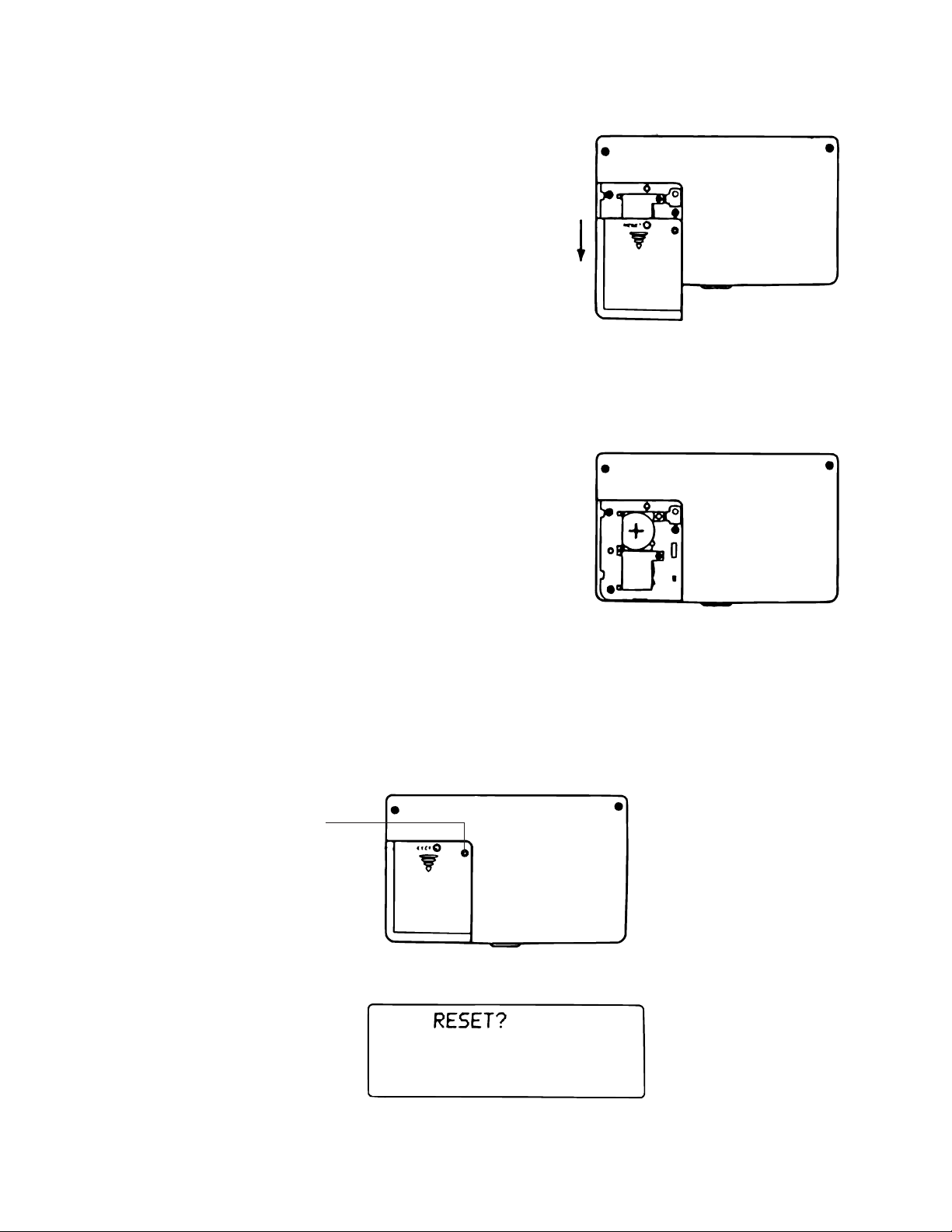
REPLACING THE BATTERIES
1. Loosen the screw on the back of the unit that holds the battery
compartment cover in place, and remove the cover by sliding
it to the direction indicated by the arrow.
2. Loosen the screw that secures one of the two battery holders
in place and remove the battery holder.
Caution: Be sure to remove only one battery at a time.
Otherwise, you will lose all data stored in memory.
3. Replace the old battery with a new one, making sure that the
positive (+) side of the new battery is facing up (so you can
see it).
4. Replace the battery holder and secure it by tightening its screw.
•Be careful that you do not overtighten the screw.
5. Repeat Steps 2 through 4 for the other battery.
•Be sure to replace both batteries. Never mix old batteries
with new ones, and be sure to use CR2032 lithium batteries
only.
6. After you replace both batteries, replace the battery compartment cover and secure it by tightening its screw.
•Be careful that you do not overtighten the screw.
TO RESET THE UNIT'S MEMORY
Warning!
The following procedure erases all data stored in the memory of the unit. Perform the following operation
only when you want to delete all data and initialize the settings of the unit.
Remember — you should always keep copies of important data by writing it down.
RESET button
1. Switch on power and press the RESET button with a thin, pointed object.
Warning!
The next step deletes all data stored in the unit's memory. Make sure that you really want to delete the data
before you continue!
— 2 —
Page 5
2. Press EXE to reset the memory and delete all data or any other key to abort the reset operation without
deleting anything.
Following the reset operation described above, the Home Time display appears and the unit settings are
initialized as noted below.
Home Time: 12-hour format
JAN/1/1995
AM/12:00 00
Zone: Tokyo (TYO)
World Time: London (LON)
Daily Alarm: 12:00 AM
Sound: Reminder alarm → OFF
Daily alarm → OFF
Key input tone → OFF
Hourly time signal → OFF
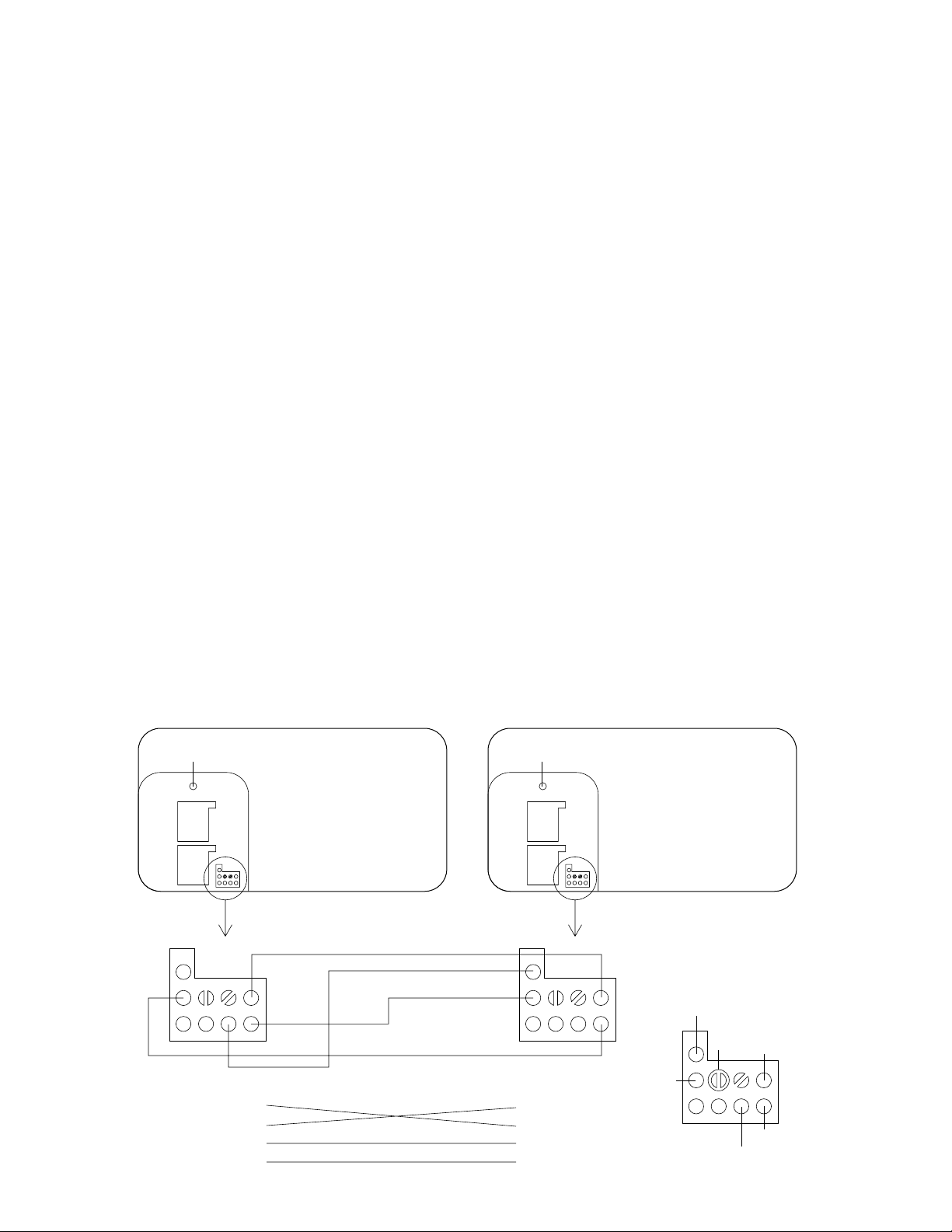
TO SAVE THE DATA
The unit can transfer the data stored to another unit.
CAUTION: Before connecting wires, be sure to put the units in transmission and receiving mode.
Furthermore, after completing saving data, remove wires while showing OK or NG on display. If no, data
stored in customer's unit are corrupted.
To save the data, the following steps must be followed;
1. Remove the battery cover of both units.
2. Press RESET button of both units.
3. Short the pad TR of customer's unit. (Display shows "T".)
4. Short the pad TR twice of slave unit. (Display shows "R".)
5. Connect 4 terminals on PCB with wires as shown in the figure below.
Customers Slave
RESET button RESET button
Enlarge Enlarge
CP12
CP10
CP11
CP13
CP2
— 3 —
CP10
CP11
CP12
CP2
CP10
TR
CP2
CP11
CP13
Page 6

6. Press SET key of customer's unit. (No display)
7. Press SET key of slave unit. (No display) (Saving data is completed, the display shows OK.)
8. Remove 4 wires while showing OK on display.
9. If the display shows NG, execute the above operation from 2.
OPERATION CHECK
Bottom View
RESET button
Batteries
No.
RESET
1
EXE
2
(SEARCH) 3, 4 times
3
OPERATION
MENU
MENU
DISPLAY
RESET?
Enlarge
1TEL 2SCHD 3REM
4SEC 5TIME 6ALM
7
MEMO
8CAL
1TEL 2SCHD 3REM
4SEC 5TIME 6ALM
7
MEMO
8CAL
TEST pad
NOTE
RESET
Contrast adjustment
4
5
6
TEST pad
TEST pad
TEST pad
Confirm display and high-pitched
buzzer sound.
All dots
Confirm display and alarm sound.
Vertical stripes.
Confirm display and low-pitched
buzzer sound.
Vertical stripes.
— 4 —
Page 7

NO.
OPERATION
TEST pad
DISPLAY
NOTE
7
TEST pad
(Takes 5 min.)
8
ON 1
9
A S D F G H J K
L Z X C V B N M
10
2 3 4 5 6
9 0
SYMBOL
EXE EXE
EXE 7 8
(SEARCH)
EXE
No display
= OK =
ALPHA
= NG =
ALPHA
USER MODE (TEL)
NAME?
ALPHA
ASDFGHJKLZXCVBNM
TEL 23456
FAX 7890!
ALPHA
EDIT DEL DEL INS SPACE
11
CLEAR A EXE CAPA
12
OFF
13
ON
RESET
14
EXE
15
_FGHJKLZXCVBNM
TEL 23456
FAX 7890!
ALPHA
◆CAPACITY◆ 0%
USED 0
FREE 32768
ALPHA
No display
RESET?
1TEL 2SCHD 3REM
4SEC 5TIME 6ALM
7
MEMO
MENU
RESET
8CAL
— 5 —
Page 8

NO.
(SEARCH) , 3 times
16
OPERATION
LOW BATTERY TEST
MENU
DISPLAY
1TEL 2SCHD 3REM
4SEC 5TIME 6ALM
7
MEMO
8CAL
NOTE
NO.
ON
1
OFF
2
OPERATION
TROUBLESHOOTING
SYMPTOM
No power
DISPLAY
LOW BATTERY !
MENU
CAUSE
Battery shortage
Poor contact of battery terminals
Defective TAB-LSI
NOTE
VDD is 5.07V or below.
SOLUTION
Replace batteries
Replace or polish them
Replace it
No display or wrong display
Poor contact SW1
Poor soldering of power supply circuit
Defective PCB unit
Defective TAB LSI
Defective heat seal
Defective LCD
Poor soldering of power supply circuit
— 6 —
Replace it
Resolder them
Replace it
Replace it
Replace it
Replace it
Resolder it
Page 9

SCHEMATIC DIAGRAM
Main PCB (1/2)
— 7 —
Page 10

Main PCB (2/2)
— 8 —
Page 11

EXPLODED VIEW
1
2
3
4
5
H
6
7
8
9
0
A
B
C
D
I
J
K
L
M
N
O
P
Q
E
F
G
R
S
T
U
— 9 —
Page 12
AT :
SF-A7
BT :
PARTS LIST
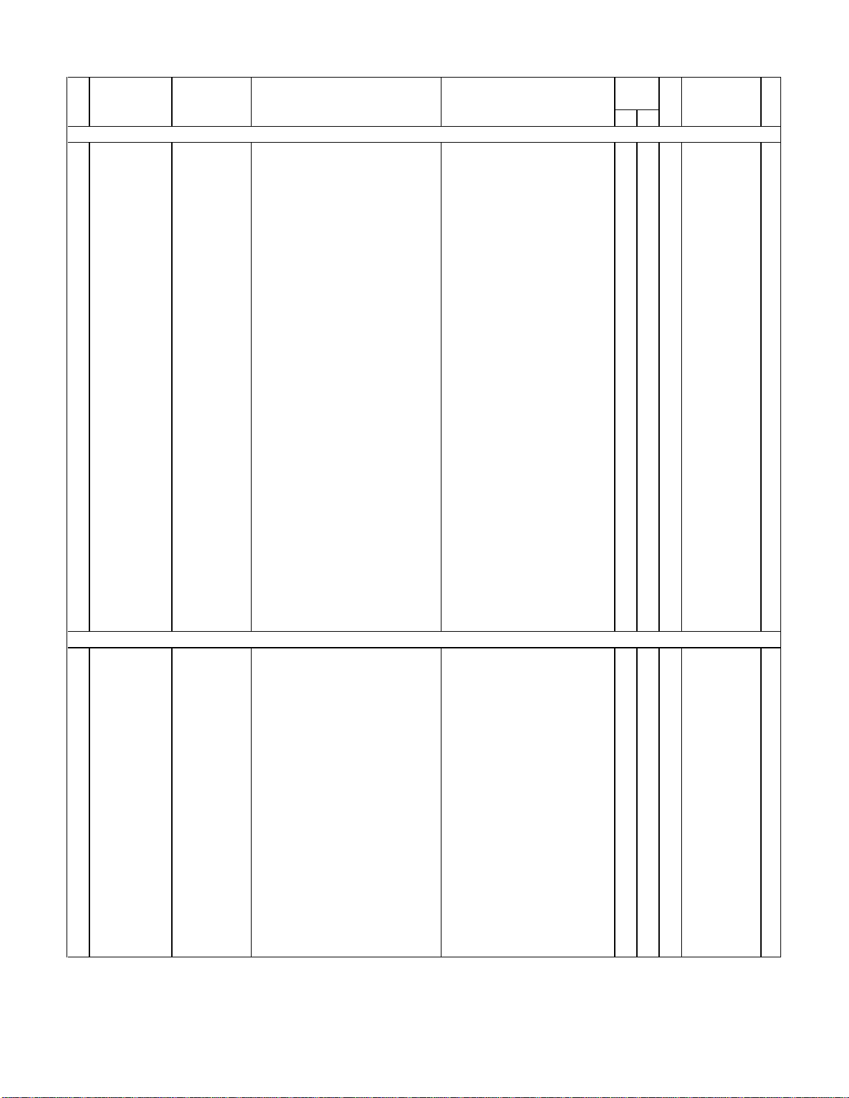
N Item Code No. Parts Name Specification Q'ty M N.R.Yen R
AT BT Unit Price
PCB ASS'Y
N 5 5610 8580 Heat seal FX200P50302
N 6 3335 5488 LCD CD426-TS
N 7 6414 5410 Sponge cushion FH100030001
N 11 6414 5420 Spacer EL000L98109
12 6410 0830 Blind tape L180 A414656-1
20 6403 9330 Tape C-L170 A413108-1
22 6409 6300 Battery plate (+) EF01DB20102
23 6409 6310 Battery plate (-) EF02DB10100
C1,C15,C18 2803 6806 Capacitor 10MS510M-MW
N C11,C13 6414 5530 Chip capacitor CP018C612T1
N C16 6054 3080 Chip capacitor CP001B612T7
N C17 6414 5500 Chip capacitor CP120F602T6
C2,C3 6511 7510 Chip capacitor CP018F602A7
C4,C5 6511 7520 Chip capacitor CP030F602T7
C6,CB1,CB2 6511 7560 Chip capacitor CP001A432T8
C7~C10
D1 2390 2135 Diode BC20MA740T0
N D2 6414 5510 Diode BC1SB007BT8
D3,D4 2315 0212 Chip diode MA153-(TX)
IC2 2105 3297 IC S-80752AN-JG-T1
IC6 2105 1568 IC TC7S32F-TE85R
N LSI1 6413 1460 COF3008-F1 sub ass'y A340092*1
LSI2 2011 3955 LSI uPD43256BGU-B12
R1,R2 6512 1360 Chip resistor CC0012D11T6
R3 6512 1440 Chip resistor CC0016D11T4
N R4 6414 5520 Chip resistor CC2003D11T1
N R5 6414 5490 Chip resistor CC0562D11T8
N R6 6414 5480 Chip resistor CC0470D11T0
X1 6510 4550 Crystal BD0063P2509
X2 6414 5460 Ceramic oscillator BD0078P4605
COMPONENT
N 1 6414 5670 Hard case FC10L981016
N 1 6414 5270 Hard case FC10L981008
N 2 6414 5660 Operation label HGF00004009
N 2 6414 5260 Operation label HGF00003509
N 3 6414 5380 Display plate EL5F0016106
N 3 6414 5630 Display plate EL5F0016203
4 6410 9670 Push button FB3DB100001
N 4 6414 5600 Push button FB3DB100108
N 8 6414 5330 Screw MAB20103201
N 9 6414 5310 PCB ass'y L98XXX0300V*1
10 3122 2380 Buzzer EFB-S55C41A8
13 6408 5920 SW knob ass'y DB2AXX4A00M
N 14 6414 5640 Lower cabinet FAB0L981013
N 14 6414 5230 Lower cabinet FAB0L981005
N 15 6414 5250 Battery cover label HGF00003606
N 16 6414 5650 Battery cover FAD0L981010
N 16 6414 5240 Battery cover FAD0L981001
N 17 6414 5390 Screw MAA90004302
N 18 6414 5350 Upper cabinet FAA0L981009
Notes: N – New parts R – A : Essential
M – Minimum order/supply quantity B : Stock recommended
R – Rank C : Others
Q – Quantity used per unit X : No stock recommended
1 5 80 C
1
1 1 260 A
1
220 5 X
2
120 5 X
1
120 10 X
1
120 6 X
1
220 16 X
2
220 16 X
2
320 13 C
3
220 11 C
2
120 16 C
1
120 11 C
1
220 11 C
2
220 11 C
2
720 7 C
7
1 5 50 C
1
110 30 C
1
210 33 C
2
110 47 C
1
120 27 B
1
1 1 670 A
1
1 1 690 B
1
220 3 C
2
120 3 C
1
120 3 C
1
120 3 C
1
120 3 C
1
1 5 55 X
1
1 5 80 C
1
1 5 80 X
0
0 5 80 X
1
110 30 X
0
010 30 X
1
0 5 70 X
1
1 5 70 X
0
0 1 130 X
1
1 1 130 X
0
320 3 X
3
1 1 2,070 B
1
110 36 X
1
110 30 B
1
110 40 X
0
010 40 X
1
120 10 X
1
110 30 C
0
010 30 C
1
120 3 X
1
0 1 120 X
1
DC-8000
FOB Japan
— 10 —
Page 13

FOB Japan
N Item Code No. Parts Name Specification Q'ty M N.R.Yen R
AT BT Unit Price
N 18 6414 5620 Upper cabinet FAA0L981017
N 19 6414 5320 Rubber sheet LAOL9810001
N 19 6414 5610 Rubber sheet LA0L9810108
21 6510 4500 Buzzer tape HGFC0000501
24 6510 4440 Insulation seal HGFC0001206
N 25 6414 5370 Overlay mylar EL4F0007105
26 6512 1080 Nut MD100000602
27 6511 8400 Key contact rubber LADB0220105
N 28 6414 5340 Screw MAB20106307
29 6409 6120 Battery holder ECDB1011108
30 6409 6210 Battery change label HGC00001102
31 6512 0990 Screw MAA80006329
1 1 120 X
0
0 1 250 X
1
1 1 250 X
0
120 17 X
1
320 6 X
3
120 10 X
1
320 13 X
3
120 10 X
1
520 3 X
5
120 26 X
1
120 7 X
1
220 3 X
2
Notes: N – New parts R – A : Essential
M – Minimum order/supply quantity B : Stock recommended
R – Rank C : Others
Q – Quantity used per unit X : No stock recommended
— 11 —
Page 14

MA0500751A
 Loading...