

Page 1
PZ-700
(without price)
INDEX
Model-C: Europe
Model-E: Other Countries
PORTABLE CD PLAYER
Page 2

CONTENTS
Disassembly Instructions.............................................................................................................. 1
CD Adjustment ............................................................................................................................... 2
Block Diagram ................................................................................................................................ 3
Troubleshooting............................................................................................................................. 4
PCB Views ...................................................................................................................................... 7
CD AMP PCB Top View.............................................................................................................7
CD AMP PCB Bottom View........................................................................................................ 8
Wiring Diagram............................................................................................................................... 9
Schematic Diagram...................................................................................................................... 10
Parts List....................................................................................................................................... 11
Exploded View.............................................................................................................................. 13
Page 3
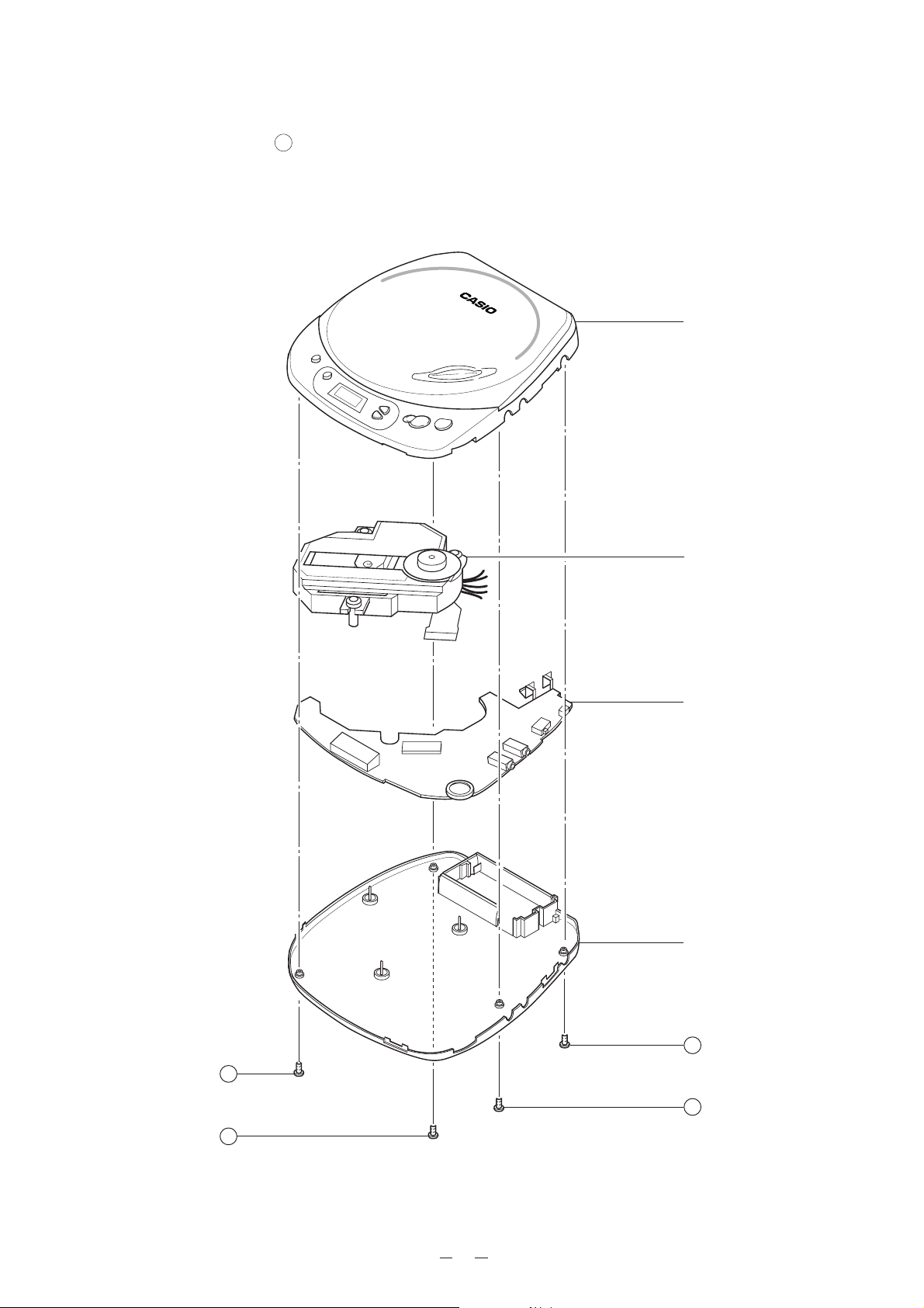
DISASSEMBLY INSTRUCTIONS
1. Remove four screws A holding the top case.
2. Remove the CD mechanism.
3. Remove the CD AMP PCB.
Upper case
CD mechanism
CD AMP PCB
Lower case
A
A
A
A
1
Page 4
CD ADJUSTMENT
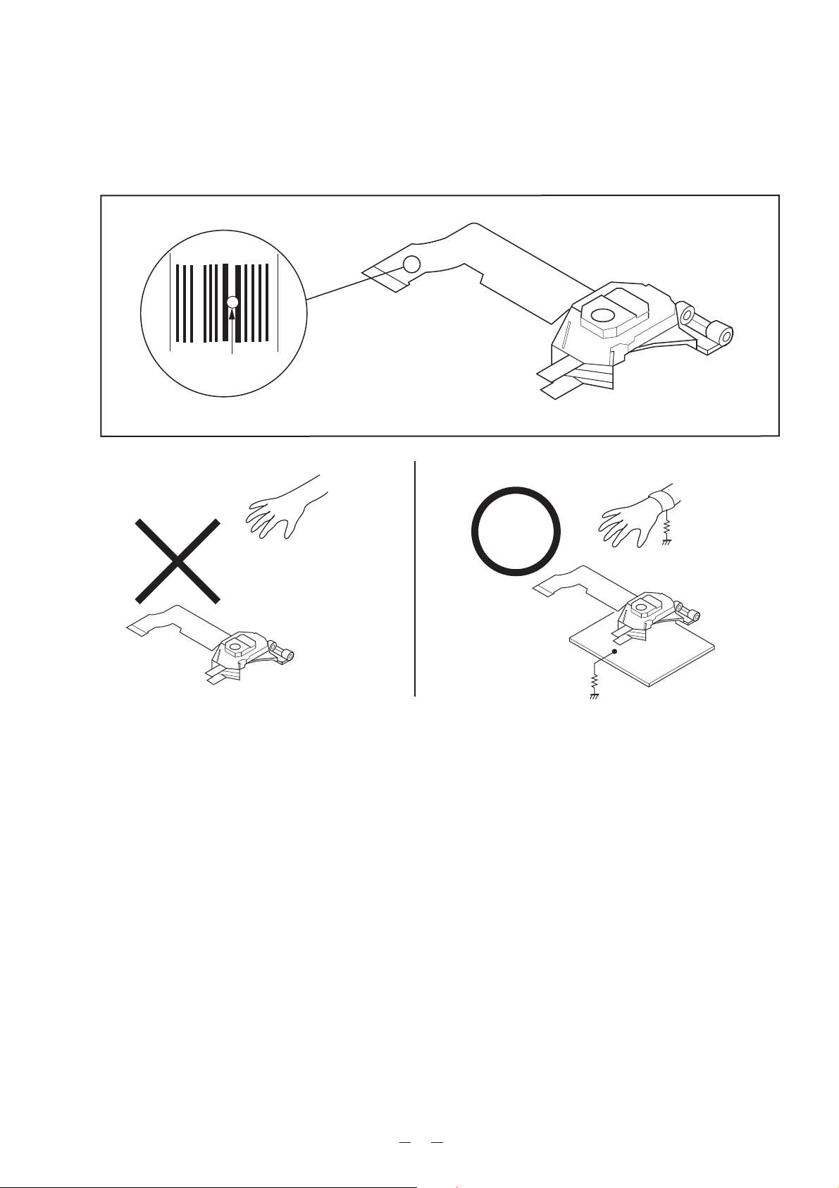
Precautions
To prevent damage caused by static electricity, the following procedures for grounding is requir or repairing the
unit.
Shorting tab
Desolder here
Pickup
[Note] Remove the connection after installed.
1. Wrist-Strap
for grounding
1MΩ
1MΩ
Pickup
2. Conductive Sheet
1. Grounding for the human body
Be sure to put on a wrist-strap for grounding (with impedance lower than 106 Ω) whose other end is grounded.
The strap works to drain away the static electricity build-up on the human body.
2. Grounding for the work table
Be sure to lay on the table a conductive sheet (with impedance lower than 106 Ω) such as a sheet of copper
which is grounded.
3. As static electricity build-up on clothes is not drainded away, be careful not to let your clothes touch the unit.
4. The short-pad on the pick-up PCB of a spare part is short-circuited for protection during shipment. To open
the short circuit, remove the soldering quickly with a soldering iron whose insulation resistance is larger than
10MΩ after connection to a suitable APC circuit.
Equipment Required
* Multi Meter
* Oscilloscope
* Compact Disc
* Dummy Load 10 kΩ
2
Page 5
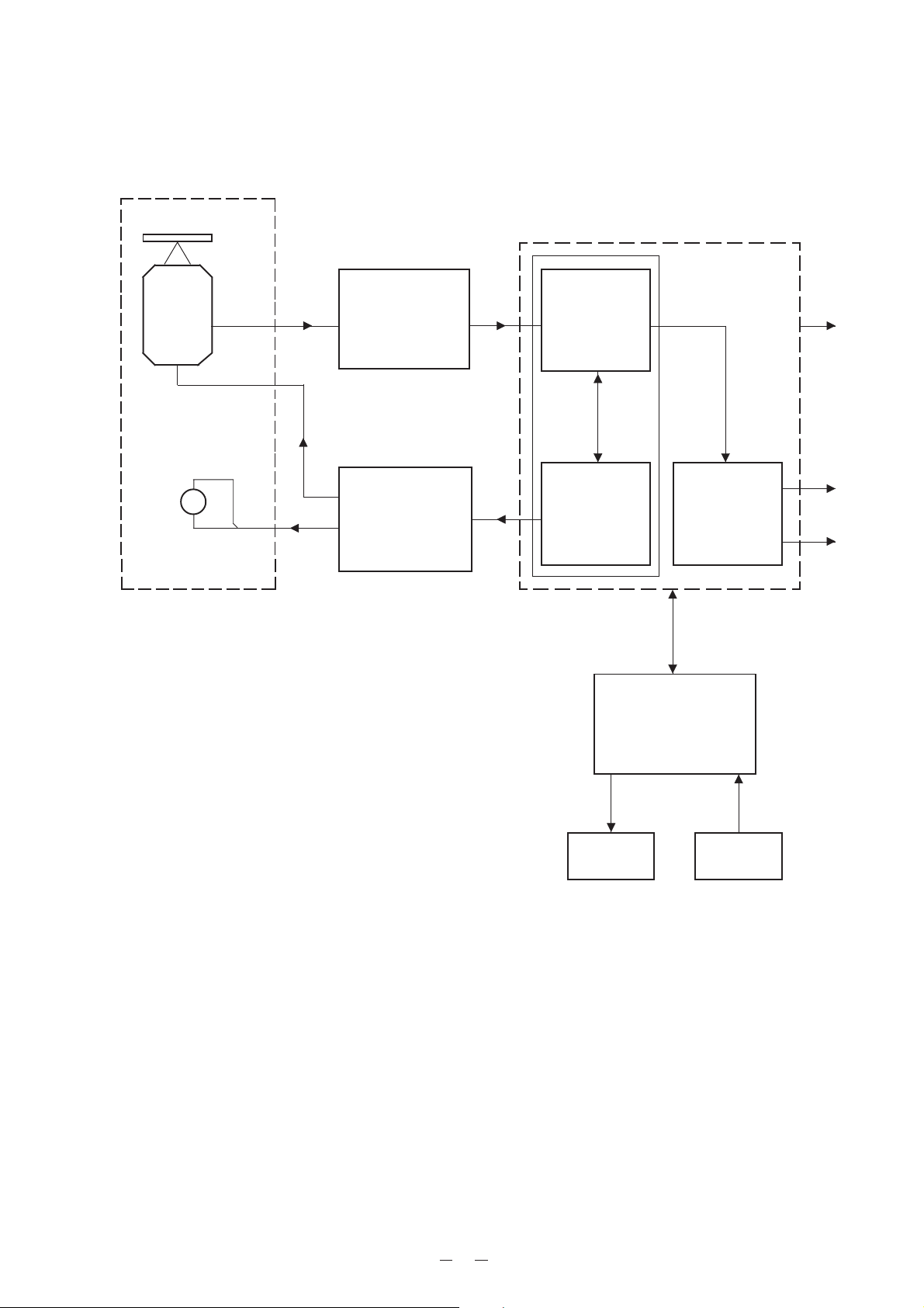
CD Mechanism
BLOCK DIAGRAM
Pickup
Spindle
Motor
Disc
Super 1chip digital servo processor
MN662740RE
Head AMP
AN8806SB
M
Driver
AN8819NFB
Digital Signal
Processing
Digital Servo
Processing
DF-DAC
TX
L ch
R ch
Microcomputer
MN150413 (4 bits)
LCD KEY
3
Page 6

TROUBLESHOOTING
Press the “PLAY/PAUSE” key.
Is “00” displayed
on the LCD ?
Yes
Load a CD and close the CD door.
Are total track
number displayed ?
Yes
Is the audio signal
present at the headphone
terminal ?
Yes
No
No
No
1
2
3
Press or key.
Can a selected
track number be searched
smoothly ?
Yes
Set “CHARGE” switch “ON”.
Is “BATT”
displayed on the LCD ?
Yes
OK
No
4
No
5
*Only when batteries are in the
CD player and AC adaptor is
connected.
4
Page 7

Repair Item 1: At power on, “00” is not displayed.
1
Is the switch
“HOLD” set “OFF” ?
Yes
Is the voltage
3.25 !0.1V at terminal
TP1 ?
Yes
Does clock
pulse appear at pin 15 of
IC801 ?
Yes
* Check IC801.
* Check the circuit around IC801.
* Check LCD801.
No
No
No
Repair Item 2: Total track number is not displayed.
* Set the “HOLD” switch “OFF”.
* Check IC502.
* Check the circuit around IC502.
* Check the Q401, Q402, T401 circuit.
* Check IC601.
* Check the X601.
* Check the circuit around IC601.
2
Does the LASER emit ?
Yes
Does the lens move
up and down ?
Yes
* Check IC501 and IC601.
* Check the circuit around IC501 and
IC601.
No
No * Check IC502.
* Check >3V appears at pin 3 of IC501.
* Check IC501.
* Check Q501.
* Check the circuit around IC502.
5
Page 8

Repair Item 3: The audio signal is not present in headphone Terminal.
3
Is the audio signal
present in “LINE OUT”
jack ?
Yes
* Check IC301.
* Check the circuit around IC301.
No
* Check IC601.
* Check the circuit around IC601.
Repair Item 4: A selected track number can’t be searched.
4
* Check the pickup.
* Check the FL wire connector.
* Check IC502.
Repair Item 5: “BATT” is not displayed on the LCD.
5
Is the level
“LOW” at pin 35 of
IC801 ?
Yes
* Check LCD801.
* Check IC801.
No
* Check Q404.
* Check S402.
6
Page 9

CD AMP PCB Top View
PCB VIEWS
7
Page 10

CD AMP PCB Bottom View
8
Page 11

WIRING DIAGRAM
CD Mechanism
KSS-542
Blue
White
Red
9
Page 12

A/L
VC
VCC
LD
GLD
VR
PD
PD1
PD2
CN501
F+
FT+
T-
F
E
15
14
13
12
11
10
9
8
7
6
5
4
3
2
1
R513 91
R505 100K
VDD
C523
0.022
R506 100K
R501 33K
R502 33K
AN8806SB
CD HEAD AMP
R514 15
C511
100 6.3V
Q501
2SA933SR
TAP1
TAP2
TAP3
TAP4
TAP5
TAP6
TAP7
TP2
R525
150K
R512 27K
C522 470P
C510 470P
3635343332313029282726252423222120
PDF
PDE
PDPD
TBAL
PDER
PDFR
LOP
VCC
RF-
RFOUT
R503 820K
R504 820K
IC501
PDAC
PDLDLDON
123456789
R515
10K
C513 0.022
R517 NOP
6.8K
R516
TP6
C514
100
50V
C506
NOP
C515 4.7P
RF
C512 220 6.3V
(OGND)
R519
NOP
C516 0.1
SHORT
SHORT
SHORT
SHORT
OPEN
SHORT
OPEN
C501
0.022
C502
0.022
R510 39K
TEOUT
TP4
FEOUT
R511 56K
FE-
TE-
FBAL
IROSS
FEDUT
TEOUT
RFIN
C.ACC
ARF
C.ENV
C.EA
C.SBD
101112131415161718
C520
C518 100P
C519
0.027
C517 1 50V
C504
0.039
TP5
TEBPF
BDO
2200P
R509
220K
DET
VDET
C.SFRT
OF IR
C521
19
ENV
VREF
XRDET
GND
2200P
C503 100
C505 0.027
TP3
ARF
L502 100µH
6.3V
C507 0.1
C524
100P
VREF
C508 0.1
R523
47K
R574
330KR522 3.3K
C801
C509 4700P
C603
1000P
LCD801
12345678910111213
R802
R803
47K
47K
L801 100µH
1
220
6.3V
0.022
C803
C802
(DGND)
C604
0.022
R804
47K
PWC
21 TRV
22 TWD
23 PC
24 ECM
25 ECS
26 KICK
27 TRD
28 FOD
29 VREF
30 FBAL
31 TBAL
32 FE
33 TE
34 RFENV
35 VDET
36 OFT
37 TRCRS
38 /RF DET
39 BDO
40 LDON
TES
R602
47K
R603
620K
R505
10K
C804 1 50V
R601 3.3K
20
/RST 18
SHCK 19
414243
R604
100K
C805 100P
C601 0.022
STAT 17
BLCK 13
SUBO 15
SOCK 14
IWUTE 16
MN662740RE
CD DIGTAL SERVO
SUPER 1 CHIP LSI
44 ARF
45 IREF
46 DRF
47 DSLF
48 PLLF
R605 680
C605
0.33
646362
1
2 SEG5
3 SEG4
4 SEG3
5 SEG2
6 SEG1
7 COM3 SE00
8 COM2
9 COM1
10 COM0
11 VLCD3
12 VLCD2
13 VLCD1
14 VDD
15 OSC1
16
171819 XI
121110
MLD 9
MCLK 7
MDATA 8
IC601
49 VCOF
50 AVDD2
51 AVSS2525354555657 VSS
C607
220
6.3V
AGND
C606
0.022
61
SEG10 6059SEG13 58
SEG14 57
IC801
MN150413
µµ
µ-CON
µµ
20 /RST
21 P30 DOOR SW
22 P31 STAT
23 SBD SUBO
24 SBT SOCK
SW1
DOOR SW
W2
W3
SCHEMATIC DIAGRAM
C602 0.022
TAP6
SSEL 80
MSEL 79
PSEL 78
CSEL 77
RSEL 76
OUTR 75
AVSS1 74
OUTL 73
AVDD1 72
/TEST 71
IDSEL 70
69
68
67
66
65
64
63
62
61
59 X2
60 VDD
L602 2.2µH
22P
PGMPC70 46
PLAY P60 42
STOP P61 41
MODE P63 39
29 P10 PCON
30 P11 AMUTE3132
TAP3
C621 0.022
C622 47 6.3V
48
47
D801 1N4148
36
BATT P23
35
CHARGE P22
34
33
TAP7
TAP4
TAP5
L603
C629
10
L601 10µH
2.2µH
0.1
C630
0.02
TAP2
TAP1
6
321
DVSS1 5
DVDD1 4
58 X1
C608
0.01
R608
16.9344
47K
C609
4.7P
DGND
55545352515049
SEG13 56
F-SKIP PC71 45
HOLD PC72 44
REST PC73 43
SUBOOUT P50 38
25 P00 MCLK
26 P01 MDATA
27 P02 MLD
28 P03 MRESET
X601
MHz
C620
B-SKIP P62 40
BLKCK IRO37
R614 15K
R201
1K
R101
1K
C202 10 50V
R202
C201
100K
2200P
C102 10 50V
C101
2200P
D802 1N4148
PLAY
S802
F.SKIP
S803
PGM
S804
C625 0.1
R611 8.2K
R617 15K
R612 68K
R613 5.6K
R618 10K
R610 2.2K
R615 47K
R616 220K
C623
0.022
R102 100K
VDD
R609 10C524 100 6.3V
C554
0.1
C409 0.02
MODE
S806
B.SKIP
S805
STOP
S801
C555
0.1
TP1
C408 220 6.3V
S401A
HOLD
C627 2200P
C628 1200P
C626 0.022
AVDD
C552
0.1
C556 0.1
C557
33
10V
D551
1N5817
C558
47 6.3V Q502
R403
1.5K
C407 0.01
R406 100
ON
S401B
OFF
SW
C553
0.1
Q401
1702N
TRVSTOP CRIP
22
PC 20
23 TR
INTV 21
INSP 19
24 TR+
L501
33µH
25 FO26 FO+
27 P.GND
28 P.GND
29 SP+
30 SP31 TRV+
32 TRV33 VC
AN8819NFB
CD DRIVE &
CONVERTER
34 TB
35 RESET
36 MRST
IC502
DC-DC
37 EMPT1
R555 47
KTA127Y
C405 0.1
R402 10
C408
T401
47P
2
Q402
1702N
(MGND)
C404
0.022
D402 1N4148
C403
0.022
C410
220
10V
Notes:
1. All resistance values are in ohms (k=1000 ohms, M=1000 kohms).
2. All capacitance values are In µF (P=10-6 µF).
3. All resistors are 1/8 watt, unless otherwise specified.
INTR 17
INFD 16
VREF 15
LDON 18
DRVCC 14
38 CLK
39 START
40 PDWER
41 CT
42 PWMC4344
C565 2.2 50V
C567 390P
R558
3.3K
3
1
C404
47
6.3V
Batteries
UM3x2
C551
33
6.3V
12
SVCC 11
AVDD 13
VSEN 10
BSEL 9
SPRO 8
SGND 7
DRGND 6
IN 5
FB 4
OUT 3
DED 2
PVCC 1
C568 0.01
R556 470K
R551 220
C559 1 50V
R552 8.2K
C550 0.022
C561 0.1
R557
22K
C565 47P
C103
10 16V
VOLUME VOLUME
4
2
C310 33 6.3V
R302
27
C312
0.1
R409
NOP
R408
100K
C401 0.01
R401
C563 100P
C301
1µ
Q302
DTA124EK
D303 1N14148
Q101
DTC143TKA
R104
R204
22K
22K
R105 1K
VR301
1
C104
C204
1000P
1000P
5 4 3 2 1
REF LIN PWO RIN P/S
IC301 LA4533M
Vcc Lout GND Rout Tmute
6 7 8 9 10
R303 33K
C311
220 10V
ON OFF
ON OFF
S402A S402B
CHARGE
27
R411 470
R553 10K
R554 5.6K
Q201
DTC143TKA
C203
10 16V
5
3
R205
1K
Q303
DTC343TK
C106 220 10V
C206 220 10V
Q404
DTC114
TKA
R410
100K
C562 100 6.3V
R108 100K
C108 0.47
R208 100K
C208 0.47
390
R107
0.1
R207
C107
L401
LED401
390
CN502
CN503
CN504
REST SWD302 1N14148
2
3
1
OFF
ON
OFF
ON
Headphone
2
3
1
C207 0.1
1
3
2
C411 0.01
TRVTRV+
SPSP+
J301
Line Out
SW301A
BBS
SW301B
BBS
J302
J401
DC JACK-
DC1
Page 13

PARTS LIST
PZ-700
Notes: 1. Prices and specifications are subject to change
without pointer notice.
2. As for spare parts order and supply, refer to the
“GUIDEBOOK for Spare parts Supply”, published
separately.
3. The numbers in item column correspond to the
same numbers in drawing.
11
Page 14

N Item Code No. Part Name Specification Q'ty Rank Remark
ELECTRICAL PARTS
ICs
N IC301 1915 7516 IC/HEADPONE AMP/LA4533M
N IC501 1915 7517 IC/HEAD AMP/AN8806SB
N IC502 1915 7518 IC/DRIVER/AN8819NFB
N IC601 1915 7515 IC/SUPER/MN662740RE
N IC801 1915 7514 IC/MICROCOMPUTER/
MN150413GHA
JACKS
N J301 1915 7508 JACK/STEREO EARPHONE/3.5MM,
TC38-072
N J302 1915 7509 JACK/STEREO EARPHONE/3.5MM,
TC38-072
N J401 1915 7510 JACK/DC POWER/TC18-073-02
LCD
N LED401 1915 7526 LCD/DISPLAY-CDP14
SWITCHES
N S301,401 1915 7505 SWITCH/SLIDE/SKC-22D02S-G2-NS
N S402 1915 7506 SWITCH/DETECTOR/ESE11SV1
N S801~806 1915 7507 SWITCH/TACT/5MM 100GF/
TS-065001-100
TRANSISTORS
N Q101,201 1915 7521 TRANSISTOR/DTC143TKA
N Q302 1915 7520 TRANSISTOR/DTA124EK
N Q303 1915 7522 TRANSISTOR/DTC343TK
N Q401,402 1915 7525 TRANSISTOR/1702N
N Q404 1915 7519 TRANSISTOR/DTC114TKA
N Q501 1915 7523 TRANSISTOR/2SA933SR
N Q502 1915 7524 TRANSISTOR/KTA1271Y
VARIABLE RESISTOR
N VR301 1915 7504 VOLUME/ROTARY/PRC1001GB
-(UPV)-C10K-T20A15D16
MECHANICAL PARTS
N 1 1915 7493 CASE/TOP
N 2 1915 7494 CASE/BOTTOM
N 3 1915 7495 DOOR/CD
N 4 1915 7496 COVER/BATTERY
N 5 1915 7497 KNOB/PLAY
N 6 1915 7498 KNOB/MODE
N 7 1915 7499 KNOB/OPEN
N 8 1915 7500 KNOB/SLIDE
N 9 1915 7502 WINDOW/LCD
N 10 1915 7501 LENS/CD DOOR
N 11 1915 7511 CONNECTOR/FPC/15PIN,
SLW 15-1C7
N 12 1915 7527 CD MECHANISM/KSM-542BAA
ACCESSORIES
N 1915 7513 EARPHONE/STEREO, H102-009
N 1915 7503 AC ADAPTOR/EI-41 4.5V500MA
(AO3497)
N 1915 7512 PLUG ADAPTOR/IR40,
CCT5902-0701
OTHER
N 1915 7528 CHE01-SMT-CDP14
Note : N - New parts
29-25453365-00
29-25880685-00
29-25881985-00
29-25274085-00
29-25041385-00
19-12100123-00
19-12100124-00
19-62100108-00
55-35100116-00
18-31100212-00
18-45100100-00
18-62100109-01
29-36014380-00
29-36012481-00
29-36034300-00
29-36170250-00
29-36011480-00
29-36093380-09
29-36127190-05
17-10100105-00
10-01011101-00
10-02008901-00
10-03009604-00
10-03009701-00
10-05025001-00
10-05025100-00
10-05025201-00
10-05025300-00
10-08008801-01
10-08008700-00
19-82100101-00
89-10100105-00
27-12100133-00
16-90100192-00
19-87001001-00
99-50141211-01
1 A
1 A
1 A
1 A
1 A
1 B
1 B
1 B
1 B
2 C
1 C
6 C
2 B
1 B
1 B
1 B
1 B
1 B
1 B
1 B
1 X
1 X
1 X
1 C
1 C
1 C
1 C
2 C
1 X
1 X
1 B
1 B
1 C
1 C
1 C
1 X
PZ-700 Common
PZ-700 Common
PZ-700 Common
PZ-700 Common
PZ-700 Common
PZ-700 Common
PZ-700 Common
PZ-700 Common
PZ-700 Common
PZ-700 Common
PZ-700 Common
PZ-700 Common
PZ-700 Common
PZ-700 Common
PZ-700 Common
PZ-700 Common
PZ-700 Common
PZ-700 Common
PZ-700 Common
PZ-700 Common
PZ-700 Common
PZ-700 Common
PZ-700 Common
PZ-700 Common
PZ-700 Common
PZ-700 Common
PZ-700 Common
PZ-700 Common
PZ-700 Common
PZ-700 Common
PZ-700 Common
PZ-700 Common
PZ-700 Common
PZ-700 Common
PZ-700 for others
PZ-700 Common
12
Page 15

Case
3
9
EXPLODED VIEW
10
1
12
6
7
5
11
8
8
2
4
13
Page 16

AF0400181A
CASIO TECHNO CO.,LTD.
Overseas Service Division
8-11-10, Nishi-Shinjuku
Shinjuku-ku, Tokyo 160-0023, Japan
 Loading...