


QT-6600
Touch Screen Smart Terminal
———————————————————————
Reference Manual
Version 1.1 December 2008
C
c

Preface
This manual is intended to be used as a reference to the QT-6600 system. It provides details to allow whole understanding of the system capabilities, its operation, and how it can be used to solve many problems within the retail outlet. This manual does not describe actual programming, which is covered in the QT-6600 programming manual.
This manual consists of the following chapters:
1.Introduction
This chapter describes the concepts of development of the QT-6600 system.
2.Hardware configuration
This chapter outlines the hardware, optional devices and configurations of QT-6600 system.
3.Application systems
This chapter outlines the application system and overviews the function provided for the QT-6600 system.
4.Manager operation
This chapter explains the manager operations to use QT-6600 system.
5.Registrations
This chapter explains actual registration operations with example.
6.Refund mode operation
This chapter explains registrations in the RF or REG– mode.
7.Read and reset
This chapter explains detail of the read and reset operations and reports.
8.Appendices
These chapters show the record format and descriptions of individual files, total calculation method, meaning of error messages, etc.
•System down and recovery (in the Installation and Down Recovery manual)
This chapter explains actions to take and recovery methods when the system goes down.
Note: Casio reserves the right to change equipment and specifications without obligation and notification. The terms used in this manual may be different from those used in other manuals of Casio’s product.
Printing history
Manual version |
Software version |
|
|
Version 1.0 |
: November, 2008 |
First Edition: November, 2008 |
Version 1.0 |
Version 1.1 |
: December, 2008 |
Second Edition: December, 2008 |
Version 1.1 |
Revised points
R-2

Introduction
The QT-6600 is a versatile intelligent terminal developed in accordance with the following concepts.
1)System concept
Developing a high performance economical system by adopting the restaurant, bar, fast food system.
–Shared check tracking
The QT-6600 system has the capability of check tracking system.
–Shared printer system
All terminals in the cluster can share remote printer(s).
–Collection, consolidation, and auto-program functions
The QT-6600 system is equipped with these functions by utilizing high-speed in-line data transfer system.
–Versatile terminal
With the QT-6600 system, any terminal has the same function, and can be designated as the master terminal by programming.
2)Software concept
A flexible application system for development, adopting the following methods:
– Function classified application system
3)Terminal hardware concept Color LCD with touch panel
In addition to the above, the QT-6600 is also a terminal following characteristics:
–Expandability
The QT-6600 system can be connected to various peripheral devices (slip printer, modem, a personal computer, etc.)
–Reliability
The QT-6600 is provided with a self-diagnosis program so that the terminal can check the hardware. When a malfunction occurs during processing, an error report is logged into the system memory so that the error can quickly be corrected.
QT-6600 Reference Manual |
R-3 |

Contents
To prevent malfunctions caused by the weak batteries, charge the memory protection batteries for over 12-hours before installation or after a longtime vacation (over 30 days).
•Before installation, initialize the terminal and leave it power on over 12-hours.
•After a longtime vacation, initialize the terminal and restore the program data if the terminal is in malfunction, and leave it power on over 12-hours.
•QT-6600 consumes batteries for saving data during 2 minutes after turning off the terminal.
•Do NOT power off the terminal over 10 times while a short term. (Except INIT or FC operation) Otherwise, it makes weak batteries.
R-4

1. |
Hardware configuration ..................................................................... |
R-10 |
|
1-1. |
|
General configuration ............................................................................................ |
R-10 |
1-2. |
|
Hardware diagram ................................................................................................. |
R-11 |
1-3. |
|
Keyboard ............................................................................................................... |
R-12 |
1-4. |
|
Display................................................................................................................... |
R-13 |
1-5. |
|
Cash drawer .......................................................................................................... |
R-14 |
1-6. |
|
Input/output connectors......................................................................................... |
R-15 |
1-7. |
|
Optional peripherals .............................................................................................. |
R-16 |
1-8. |
|
System configuration ............................................................................................. |
R-17 |
2. |
Application systems........................................................................... |
R-23 |
|
2-1. General description of application system ...................................... |
R-23 |
||
2-1-1. |
File concept ........................................................................................................... |
R-23 |
|
2-1-2. |
Linkage of totalizers .............................................................................................. |
R-24 |
|
2-1-3. |
Function keys ........................................................................................................ |
R-25 |
|
2-1-4. |
Keyboard layout ..................................................................................................... |
R-25 |
|
2-1-5. |
Mode control ......................................................................................................... |
R-26 |
|
2-1-6. Operation prompt and error messages ................................................................. |
R-26 |
||
2-1-7. |
Printing control system .......................................................................................... |
R-26 |
|
2-2. General description of individual function keys ............................. |
R-29 |
||
2-2-1. |
System keys .......................................................................................................... |
R-29 |
|
2-2-2. |
Finalize keys .......................................................................................................... |
R-30 |
|
2-2-3. |
Transaction keys .................................................................................................... |
R-30 |
|
2-3. |
Remote printer control ....................................................................... |
R-39 |
|
2-3-1. Remote printer system configuration .................................................................... |
R-39 |
||
2-3-2. Remote printer control setting ............................................................................... |
R-40 |
||
2-3-3. Remote printer output control................................................................................ |
R-41 |
||
2-3-4. Remote printer backup processes ........................................................................ |
R-41 |
||
2-4. |
Check tracking system....................................................................... |
R-44 |
|
2-4-1. Shared check tracking system .............................................................................. |
R-44 |
||
2-4-2. Shared check tracking requirement....................................................................... |
R-45 |
||
2-4-3. Data backup when the master goes down ............................................................ |
R-45 |
||
2-5. Other check tracking system control ............................................... |
R-46 |
||
2-5-1. The timing to clear check detail and index file after finalization ............................ |
R-46 |
||
2-5-2. |
Table transfer ......................................................................................................... |
R-46 |
|
2-5-3. |
Store and recall ..................................................................................................... |
R-46 |
|
2-6. |
Clerk control function ........................................................................ |
R-48 |
|
2-6-1. |
Clerk interrupt ....................................................................................................... |
R-48 |
|
2-6-2. |
Clerk detail memory .............................................................................................. |
R-49 |
|
2-6-3. |
Clerk training ......................................................................................................... |
R-49 |
|
2-6-4. |
Manager mode control .......................................................................................... |
R-49 |
|
2-7. Arrangement key function and scheduler ........................................ |
R-51 |
||
QT-6600 Reference Manual |
R-5 |

Contents
2-7-1. |
Arrangement key function ..................................................................................... |
R-51 |
2-7-2. |
Arrangement program example ............................................................................. |
R-55 |
2-7-3. |
Scheduled execution of arrangement function ...................................................... |
R-55 |
2-8. |
Making graphic logo........................................................................... |
R-56 |
|
2-8-1. |
About graphic logo ................................................................................................ |
R-56 |
|
2-8-2. |
Making graphic logo procedure ............................................................................. |
R-56 |
|
2-9. |
Hourly item .......................................................................................... |
R-57 |
|
2-9-1. |
Programming necessary files before using hourly item function. .......................... |
R-57 |
|
2-10. |
Time and attendance .......................................................................... |
R-58 |
|
2-10-1. |
Corresponding relations of the file ........................................................................ |
R-59 |
|
2-10-2. |
Clock-in operation ................................................................................................. |
R-62 |
|
2-10-3. |
Clock-out operation ............................................................................................... |
R-65 |
|
2-11. |
Sign on control ................................................................................... |
R-68 |
|
2-11-1. |
Sign on .................................................................................................................. |
R-68 |
|
2-11-2. |
Solution to abnormality of master terminal ............................................................ |
R-69 |
|
2-11-3. |
Solution to abnormality of satellite terminal .......................................................... |
R-69 |
|
2-11-4. |
Sign on compulsory .............................................................................................. |
R-69 |
|
2-12. IDC (Item Data Capture) ..................................................................... |
R-70 |
||
2-12-1. |
Available capturing items ...................................................................................... |
R-70 |
|
2-12-2. |
Set up the IDC start / end ..................................................................................... |
R-73 |
|
2-12-3. |
How to memorize the captured items .................................................................... |
R-74 |
|
2-12-4. |
IDC data file structure ........................................................................................... |
R-75 |
|
2-12-5. |
IDC data type ........................................................................................................ |
R-81 |
|
2-12-6. |
Transferring IDC .................................................................................................... |
R-82 |
|
2-13. |
Electronic journal ............................................................................... |
R-83 |
|
2-13-1. |
Storing electronic journal ...................................................................................... |
R-83 |
|
2-13-2. |
Issuing electronic journal report ............................................................................ |
R-83 |
|
2-13-3. |
Displaying normal electronic journal and producing guest receipts after sales..... |
R-83 |
|
2-13-4. |
Transferring electronic journal memory ................................................................. |
R-84 |
|
2-14. Simple time and attendance .............................................................. |
R-85 |
||
2-14-1. |
Clock-in operation ................................................................................................. |
R-85 |
|
2-14-2. |
Clock-out operation ............................................................................................... |
R-86 |
|
2-14-3. |
Worktime display ................................................................................................... |
R-86 |
|
2-14-4. |
Report ................................................................................................................... |
R-86 |
|
2-15. |
Magnetic card reading ....................................................................... |
R-87 |
|
3. |
Manager operation ............................................................................. |
R-90 |
|
3-1. |
Machine initialization ......................................................................... |
R-90 |
|
3-1-1. |
INIT ....................................................................................................................... |
R-90 |
|
3-1-2. |
Flag clear .............................................................................................................. |
R-90 |
|
R-6

3-1-3. |
INIT 2 .................................................................................................................... |
R-91 |
3-1-4. |
INIT code............................................................................................................... |
R-91 |
3-2. IPL (Initial Program Loading) ............................................................ |
R-91 |
||
3-2-1. |
IPL ......................................................................................................................... |
R-91 |
|
3-2-2. |
System configuration before IPL operation ........................................................... |
R-92 |
|
3-3. |
Manager function................................................................................ |
R-93 |
|
3-3-1. |
System connection check ..................................................................................... |
R-94 |
|
3-3-2. |
Remote on............................................................................................................. |
R-95 |
|
3-3-3. |
Remote off............................................................................................................. |
R-95 |
|
3-3-4. |
Busy reset ............................................................................................................. |
R-96 |
|
3-3-5. |
Stock maintenance ................................................................................................ |
R-97 |
|
3-3-6. |
Drawer for clerk ..................................................................................................... |
R-98 |
|
3-3-7. |
CHK# (Clerk interrupt)........................................................................................... |
R-98 |
|
3-3-8. |
Order ID change.................................................................................................... |
R-99 |
|
3-3-9. |
Error log print ...................................................................................................... |
R-100 |
|
3-3-10. |
System re-configuration ...................................................................................... |
R-101 |
|
3-3-11. |
Item Data Capture ............................................................................................... |
R-102 |
|
3-3-12. |
Euro change over ................................................................................................ |
R-103 |
|
3-3-13. |
Clerk window ....................................................................................................... |
R-104 |
|
3-3-14. |
Customer............................................................................................................. |
R-105 |
|
3-3-15. |
Customer busy reset ........................................................................................... |
R-106 |
|
3-3-16. |
Sound .................................................................................................................. |
R-106 |
|
3-3-17. |
Print batch maintenance file ................................................................................ |
R-107 |
|
3-3-18. |
Execute batch maintenance file .......................................................................... |
R-108 |
|
3-3-19. |
Re-index the scanning PLU file ........................................................................... |
R-109 |
|
3-3-20. |
Licence code entry .............................................................................................. |
R-110 |
|
3-3-21. |
FTP client ............................................................................................................ |
R-110 |
|
3-3-22. |
Maintenance data................................................................................................ |
R-111 |
|
3-3-23. |
Printer logo send ................................................................................................. |
R-112 |
|
3-3-24. |
Clerk number....................................................................................................... |
R-113 |
|
3-3-25. |
Operation monitor ............................................................................................... |
R-113 |
|
3-4. |
System command execution ........................................................... |
R-114 |
|
3-4-1. |
X/Z reporting ....................................................................................................... |
R-114 |
|
3-4-2. |
X/Z collection / consolidation............................................................................... |
R-116 |
|
3-4-3. |
Remote power control ......................................................................................... |
R-116 |
|
3-5. |
Data communication system ........................................................... |
R-117 |
|
3-5-1. |
Inline / online connectors .................................................................................... |
R-117 |
|
3-5-2. |
Hardware interface .............................................................................................. |
R-118 |
|
3-5-3. |
Inline / online functions........................................................................................ |
R-120 |
|
3-6. Collection / Consolidation system .................................................. |
R-121 |
||
3-6-1. |
X/Z collection....................................................................................................... |
R-123 |
|
3-6-2. |
X/Z consolidation ................................................................................................. |
R-125 |
|
3-6-3. |
X/Z collection / consolidation............................................................................... |
R-128 |
|
3-7. |
Auto-programming function ............................................................ |
R-131 |
|
QT-6600 Reference Manual |
R-7 |

Contents
3-7-1. |
Auto-programming functions ............................................................................... |
R-131 |
3-7-2. |
Auto-program operation and CF card utilities...................................................... |
R-132 |
4. |
Registrations..................................................................................... |
R-138 |
4-1. |
Clerk sign on / off operation ................................................................................ |
R-138 |
4-2. |
Voiding the last registered item (<VOID> key operation) .................................... |
R-139 |
4-3. |
Voiding the previous registered item (<VOID> key operation)............................. |
R-140 |
4-4. |
Cancelling of all data registered during the transaction ...................................... |
R-140 |
4-5. |
Using the list function .......................................................................................... |
R-142 |
4-6. |
Using the set menu function and pulldown group function .................................. |
R-143 |
4-7. |
Post entry ............................................................................................................ |
R-146 |
4-8. |
Separate check ................................................................................................... |
R-147 |
4-9. |
Open check ......................................................................................................... |
R-148 |
4-10. |
Split payment (Dutch account) ............................................................................ |
R-148 |
4-11. |
Media change...................................................................................................... |
R-149 |
4-12. |
Eat-in / Takeout ................................................................................................... |
R-150 |
4-13. |
Scanning PLU ..................................................................................................... |
R-150 |
4-14. |
Shift PLU ............................................................................................................. |
R-153 |
4-15. |
Printing barcode on receipts (UP-400 and UP-360)............................................ |
R-153 |
4-16. |
Round repeat function ......................................................................................... |
R-154 |
4-17. |
Mix & match / coupon.......................................................................................... |
R-155 |
4-18. |
Customer............................................................................................................. |
R-156 |
4-19. |
Table sharing ....................................................................................................... |
R-157 |
4-20. |
Order character change ...................................................................................... |
R-157 |
4-21. |
Item search ......................................................................................................... |
R-157 |
4-22. |
Scan Mix & match ............................................................................................... |
R-158 |
4-23. |
Time calculation .................................................................................................. |
R-159 |
4-24. |
Additional PLU character .................................................................................... |
R-160 |
5. |
Refund mode operation ................................................................... |
R-162 |
5-1. Selecting REF or REG– mode ............................................................................ |
R-162 |
|
6. |
Read and reset operations .............................................................. |
R-164 |
6-1. |
The procedures of reading or resetting ............................................................... |
R-164 |
6-2. |
Report sample ..................................................................................................... |
R-166 |
A-1. Function key list ................................................................................... |
R-182 |
|
A-2. File format ............................................................................................. |
R-187 |
|
A-3. Counter and Totalizer calculation method ......................................... |
R-224 |
|
A-4. Error messages .................................................................................... |
R-228 |
|
R-8

1. Hardware configuration ......................................................................... |
R-10 |
1-1. |
General configuration .................................................................................... |
R-10 |
1-2. |
Hardware diagram ........................................................................................ |
R-11 |
1-3. |
Keyboard ....................................................................................................... |
R-12 |
1-4. |
Display .......................................................................................................... |
R-13 |
1-5. |
Cash drawer .................................................................................................. |
R-14 |
1-6. |
Input/output connectors ................................................................................ |
R-15 |
1-7. |
Optional peripherals ...................................................................................... |
R-16 |
1-8. |
System configuration .................................................................................... |
R-17 |
QT-6600 Reference Manual |
R-9 |

Hardware Configuration
1.Hardware configuration
This section outlines the hardware, optional devices, and configurations of the QT-6600 system.
1-1. General configuration
Front view
Touch screen panel
Display on/off key
Pilot lamp
i-Button key receiver (only for QT-6600-DLS)
Microphone
C
Stand
C
Customer display
Power switch cover
Panel fixing screw
Connector cover
Rear view
R-10
1-2. Hardware diagram
|
|
|
|
|
|
|
|
|
|
|
|
Power switch cover |
|
|
||||
|
|
|
|
|
|
|
|
|
|
|
|
|
|
|||||
|
|
|
|
|
|
|
|
|
|
|
|
|
|
|||||
screentouchkey126Max. |
|
|
|
|
|
CFcard |
|
|
|
|
|
|
|
|||||
LCDcolordot768x1024 |
|
|
|
i-Button |
CPU |
Memory |
|
|
|
FROM |
||||||||
|
|
|
|
|
|
|
|
|
|
|
|
|
|
|
|
Speaker |
||
|
|
|
|
|
|
|
|
|
|
|
|
|
|
|
|
|
|
|
|
|
|
|
|
|
|
|
|
|
|
|
|
|
|
|
|
|
|
|
|
|
|
|
|
|
|
|
|
|
|
|
|
|
|
|
|
|
|
|
|
|
|
|
|
|
|
|
|
|
|
|
|
|
|
|
|
|
|
|
|
|
|
|
|
|
|
|
|
|
|
|
|
|
|
|
|
|
|
|
|
|
|
|
|
|
|
|
|
|
|
|
|
|
|
|
|
|
|
|
|
|
|
|
|
|
|
|
|
Flash |
|
RAM |
|
NOR |
|
|
|
|
|
|
|
|
|
|
|
|
|
|
|
|
|||
|
|
|
|
|
|
|
|
|
key i/f |
|
|
|
|
32MB |
|
64MB |
|
64MB |
|
|
|
|
|
|
|
|
|
|
|
|
|
||||||
|
|
|
|
|
|
|
|
|
|
|
|
|
|
|
|
|||
|
|
|
|
|
|
|
|
|
|
|
|
|
|
|
|
|||
|
|
|
|
|
|
|
|
|
|
|
|
|
|
|
|
|
|
|
QT-6011DLS |
|
i/f1Drawer |
i/f2Drawer |
Inline |
COM1232C-RS |
COM2232C-RS |
COM3232C-RS |
COM4232C-RS |
COM5232C-RS |
COM6232C-RS |
microphoneExt. |
speakerExt. |
(except for |
|
|
|
|
|
|
|
|
|
|
|
|
QT-6600-DLS) |
|
|
|
|
|
|
|
|
|
|
|
|
|
Microphone |
|
|
|
|
|
|
|
|
|
|
|
|
MCR |
|
|
|
|
|
|
|
|
|
|
|
|
QT-6046MCR |
|
|
|
|
|
|
|
|
|
|
|
|
|
|
|
|
|
|
|
|
|
|
|
|
|
|
|
|
|
|
|
|
|
|
|
|
|
|
|
|
|
|
|
|
|
|
|
|
|
|
|
|
|
|
|
|
|
|
|
|
|
|
|
|
|
|
|
|
|
|
-CB-2 |
|
|
|
|
|
|
|
|
|
|
|
|
|
|
|
|||||||
|
|
|
|
|
|
|
|
|
|
|
|
|
|
|
|
|
|
|
|
|
|
|
|
|
|
|
|
|
|
|
|
|
||||||||
|
|
|
Drawer |
|
|
|
|
|
|
|
|
|
|
|
|
|
|
|
|
|
|
|
|
|
|
|
|
|||||||||||||
|
|
|
|
|
|
|
|
|
|
|
|
PRL |
|
|
|
|
|
|
|
|
|
|
|
|
|
|
|
|
|
|
|
|||||||||
|
|
|
|
|
|
|
|
|
|
|
|
|
|
|
|
|
|
|
|
|
|
|
|
|
|
|||||||||||||||
|
|
|
|
|
|
|
|
|
|
|
|
|
|
|
|
|
|
|
|
|
|
|
|
|
|
|
|
|
|
|
|
|
|
|
|
|||||
|
|
|
|
|
|
|
|
|
|
|
|
|
|
|
|
|
|
|
|
|
|
|
|
|
|
|
|
|
|
|
|
|
|
|
||||||
|
|
|
|
|
|
|
|
|
|
|
|
|
|
|
|
|
|
|
|
|
|
|
|
|
|
|
|
|
|
|
|
|
|
|
|
|
|
|
|
|
|
|
|
|
|
|
|
|
|
|
|
|
|
|
|
|
|
|
|
|
|
|
|
|
|
|
|
|
|
|
|
|
|
|
|
|
|
|
|
|
|
|
|
|
|
|
Drawer |
|
|
|
|
cableUTPCAT5 |
MODEM |
|
|
|
|
|
8B-8A/-CB-PRT |
8B-8A/-CB-PRT |
8B-8A/-CB-PRT |
|
||||||||||||||||||||
|
|
|
|
|
|
|
|
|
|
|
|
|
|
|
|
|
|
or |
|
|
|
|
|
|
|
|
|
|
|
|
|
|
|
|||||||
|
|
|
|
|
|
|
|
|
|
|
|
|
|
|
|
|
|
PC |
|
|
|
|
|
|
|
|
|
|
|
|
|
|
|
|||||||
|
|
|
|
|
|
|
|
|
|
|
|
|
|
|
|
|
|
|
|
|
|
|
|
|
|
|
|
|
|
|
|
|
|
|
|
|
|
|
||
|
|
|
|
AC Adptor |
|
|
|
|
|
|
|
Scanner |
|
|
|
|
|
|
|
|
|
|
|
|
|
|
|
|
|
|||||||||||
|
|
|
|
|
|
|
|
|
|
|
|
|
|
|
|
|
|
|
|
|
|
|
|
|
|
|
|
|||||||||||||
|
|
|
|
|
|
|
|
|
|
|
|
|
|
|
|
|
|
|
|
|
|
|
|
|
|
|
|
|
|
|
|
|
|
|
|
|
|
|
|
|
|
|
|
|
|
|
|
|
|
|
|
|
|
|
|
|
|
|
|
|
|
|
|
|
|
|
|
|
|
|
Remote |
|
|
Remote |
|
||||||
|
|
|
|
|
|
|
|
|
|
|
|
|
|
|
|
|
|
|
|
|
|
|
PRT-CB-8C |
|
6062CB-QTor |
|
|
|
|
|||||||||||
|
|
|
|
|
|
|
|
|
|
|
|
|
|
|
|
|
|
|
|
|
|
|
|
|
|
Power |
|
|
|
Power |
|
|||||||||
|
|
|
HUB |
|
|
|
|
|
|
|
|
|
|
|
|
|
|
|
|
|
|
|
|
|
|
|
printer |
|
|
printer |
|
|||||||||
|
|
|
|
|
|
|
|
|
|
|
|
|
|
|
|
|
|
|
|
|
|
|
|
|
|
|
|
|
|
UP-400 |
|
|
UP-400 |
|
||||||
Other terminals |
|
|
|
|
|
|
|
|
|
|
|
|
|
|
|
|
|
|
|
|
|
|
|
|
|
|
|
|
|
|
||||||||||
|
|
|
|
|
|
|
|
|
|
|
|
|
|
|
|
|
|
|
|
|
|
|
|
|
|
|
|
|
||||||||||||
|
|
|
|
|
|
Slip |
|
6061CB |
|
|
supply |
|
|
|
supply |
|
||||||||||||||||||||||||
PC or LAN printer |
|
|
|
|
|
|
|
|
|
|
|
|
|
|
|
|
|
|
|
|||||||||||||||||||||
|
|
|
|
|
|
printer |
|
|
|
|
|
|
|
|
|
|
|
|
|
|
|
|||||||||||||||||||
|
|
|
|
|
|
|
|
|
|
|
|
|
|
|
|
|
|
QT- |
|
|
|
|
Remote |
|
|
|||||||||||||||
|
|
|
|
|
|
|
|
|
|
|
|
|
|
|
|
|
|
|
|
|
|
|
|
|
|
|
|
|
|
|
|
|
||||||||
|
|
|
|
|
|
|
|
|
|
|
|
|
|
|
|
|
SP-1300 |
|
|
|
|
|
|
|||||||||||||||||
|
|
|
|
|
|
|
|
|
|
|
|
|
|
|
|
|
|
|
|
|
|
|
printer |
|
|
|||||||||||||||
|
|
|
|
|
|
|
|
|
|
|
|
|
|
|
|
|
|
|
|
|
|
|
|
|
|
|
|
|
|
|
|
|
|
UP-360 |
|
|
||||
|
|
|
|
|
|
|
|
|
|
|
|
|
|
|
|
|
|
Power |
|
Remote |
|
|
|
|
|
|
|
|
|
|
|
|
||||||||
|
|
|
|
|
|
|
|
|
|
|
|
|
|
|
|
|
|
|
|
|
|
|
|
|
|
|
|
|
|
|||||||||||
|
|
|
|
|
|
|
|
|
|
|
|
|
|
|
|
|
|
|
|
|
|
|
|
|
|
|
|
|
|
|
|
|
|
|
||||||
|
|
|
|
|
Remote |
|
|
|
|
|
|
|
supply |
|
|
|
|
|
display |
|
|
|
|
|
|
Power |
|
|
|
|||||||||||
|
|
|
|
|
printer |
|
|
|
|
|
|
|
|
|
|
|
|
|
|
|
QT-6060D |
|
|
|
|
|
|
|
|
|
||||||||||
|
|
|
|
|
|
|
|
|
|
|
|
|
|
|
|
|
|
|
|
|
|
|
|
|
|
supply |
|
|
|
|||||||||||
|
|
|
|
|
|
|
|
|
|
|
|
|
|
|
|
|
|
|
|
|
|
|
|
|
|
|
|
|
||||||||||||
|
|
|
|
|
UP-400 |
|
|
Power |
|
|
|
|
|
|
|
|
|
|
|
|
|
|
|
|
|
|
|
|
|
|
||||||||||
|
|
|
|
|
|
|
|
|
|
|
|
|
|
|
|
|
|
|
|
|
|
|
|
|
|
|
|
|
|
|
|
|||||||||
|
|
|
|
|
|
|
|
|
|
|
|
|
supply |
|
|
|
|
|
|
|
|
|
|
|
|
|
|
|
|
|
|
|
|
|
|
|
|
|
||
|
|
|
|
|
|
|
|
|
|
|
|
|
|
|
|
|
|
|
|
|
|
|
|
|
|
|
|
|
|
|
|
|
|
|
|
|
|
|||
|
|
|
|
|
|
|
|
|
|
|
|
|
|
|
|
|
|
|
|
|
|
|
|
|
|
|
|
|
|
|
|
|
|
|
|
|
|
|
|
|
Note: Shadowed device and dot line indicate option devices.
QT-6600 Reference Manual |
R-11 |
Hardware Configuration
1-3. Keyboard
1-3-1. Standard keyboard
REG |
C01 |
31-10-08 |
12:34 PM 001234 |
|
|
|
|
|
|
|
|
||||
|
|
|
|
|
|
|
|
HOME |
PLU010 |
PLU020 |
PLU030 |
PLU040 |
PLU050 |
PLU060 |
PLU070 |
|
|
|
|
|
|
|
|
PAGE |
PLU009 |
PLU019 |
PLU029 |
PLU039 |
PLU049 |
PLU059 |
PLU069 |
|
|
|
|
|
|
|
|
UP |
|||||||
|
|
|
|
|
|
|
|
|
PLU008 |
PLU018 |
PLU028 |
PLU038 |
PLU048 |
PLU058 |
PLU068 |
|
|
|
|
|
|
|
|
|
PLU007 |
PLU017 |
PLU027 |
PLU037 |
PLU047 |
PLU057 |
PLU067 |
|
|
|
|
|
|
|
|
PAGE |
PLU006 |
PLU016 |
PLU026 |
PLU036 |
PLU046 |
PLU056 |
PLU066 |
|
|
|
|
|
|
|
|
DOWN |
|||||||
|
|
|
|
|
|
|
|
|
|
|
|
|
|
|
|
|
|
|
|
|
|
•0.00 |
END |
|
|
|
|
|
|
|
|
12345678901234567890 |
PLU005 |
PLU015 |
PLU025 |
PLU035 |
PLU045 |
PLU055 |
PLU065 |
||||||||
ESC/ |
|
MODE |
SEARCH |
|
|
YES |
NO |
|
PLU004 |
PLU014 |
PLU024 |
PLU034 |
PLU044 |
PLU054 |
PLU064 |
SKIP |
|
|
|
|
|||||||||||
CLK# |
|
CLEAR |
X |
VOID |
#/NS |
COVERS |
MENU |
PLU003 |
PLU013 |
PLU023 |
PLU033 |
PLU043 |
PLU053 |
PLU063 |
|
RECEIPT |
7 |
8 |
9 |
|
SEAT# |
POST |
SEP |
PLU002 |
PLU012 |
PLU022 |
PLU032 |
PLU042 |
PLU052 |
PLU062 |
|
|
ENTRY |
CHK |
|||||||||||||
TABLE |
|
4 |
5 |
6 |
|
FUNC |
FIN. |
TBL |
PLU001 |
PLU011 |
PLU021 |
PLU031 |
PLU041 |
PLU051 |
PLU061 |
RECEIPT |
|
|
LIST |
LIST |
TRANS |
||||||||||
PLU# |
|
1 |
2 |
3 |
|
SUBTOTAL |
NB |
LIST |
LIST |
LIST |
LIST |
LIST |
LIST |
LIST |
|
|
|
|
1 |
2 |
3 |
4 |
5 |
6 |
7 |
||||||
REPORTS |
0 |
00 |
• |
|
CASH/AMT |
NEW/OLD |
MENU |
MENU |
MENU |
MENU |
MENU |
MENU |
MENU |
||
|
|
/TEND |
CHK |
1 |
2 |
3 |
4 |
5 |
6 |
7 |
|||||
1-3-2. Hard key code of keyboard
|
|
|
|
|
|
|
|
|
|
|
|
|
|
|
|
|
REG |
C01 |
31-10-08 12:34 PM 001234 |
|
048 |
060 |
072 |
084 |
096 |
108 |
120 |
132 |
|||
|
|
|
|
|
|
|
|
||||||||
|
|
|
|
|
|
|
|
|
|
|
|
|
|
|
|
|
|
|
|
|
|
|
|
047 |
059 |
071 |
083 |
095 |
107 |
119 |
131 |
|
|
|
|
|
|
|
|
|
|
|
|
|
|
|
|
|
|
|
|
|
|
|
|
046 |
058 |
070 |
082 |
094 |
106 |
118 |
130 |
|
|
|
|
|
|
|
|
|
|
|
|
|
|
|
|
|
|
|
|
|
|
|
|
045 |
057 |
069 |
081 |
093 |
105 |
117 |
129 |
|
|
|
|
|
|
|
|
|
|
|
|
|
|
|
|
|
|
|
|
|
|
|
|
044 |
056 |
068 |
080 |
092 |
104 |
116 |
128 |
|
|
|
|
|
|
|
|
|
|
|
|
|
|
|
|
|
|
|
|
|
•0.00 |
|
|
|
|
|
|
|
|
|
|
|
|
|
|
|
|
043 |
055 |
067 |
079 |
091 |
103 |
115 |
127 |
||
|
12345678901234567890 |
|
|||||||||||||
|
|
|
|
|
|
|
|
|
|
||||||
|
|
|
|
|
|
|
|
|
|
|
|
|
|
||
006 |
012 |
018 |
024 |
030 |
036 |
042 |
054 |
066 |
078 |
090 |
102 |
114 |
126 |
||
|
|
|
|
|
|
|
|
|
|
|
|
|
|
||
005 |
011 |
017 |
023 |
029 |
035 |
041 |
053 |
065 |
077 |
089 |
101 |
113 |
125 |
||
|
|
C |
|
|
|
|
|
|
|
|
|
|
|
|
|
004 |
010 |
016 |
022 |
028 |
034 |
040 |
052 |
064 |
076 |
088 |
100 |
112 |
124 |
||
|
|
7 |
8 |
9 |
|
|
|
|
|
|
|
|
|
|
|
003 |
009 |
015 |
021 |
027 |
033 |
039 |
051 |
063 |
075 |
087 |
099 |
111 |
123 |
||
|
|
4 |
5 |
6 |
|
|
|
|
|
|
|
|
|
|
|
002 |
008 |
014 |
020 |
026 |
032 |
038 |
050 |
062 |
074 |
086 |
098 |
110 |
122 |
||
|
|
1 |
2 |
3 |
|
|
|
|
|
|
|
|
|
|
|
001 |
007 |
013 |
019 |
025 |
031 |
037 |
049 |
061 |
073 |
085 |
097 |
109 |
121 |
||
|
|
0 |
00 |
• |
|
|
|
|
|
|
|
|
|
|
|
•In case of assigning a double or quadruple key, the key code of the key is shadowed part of the key.
R-12
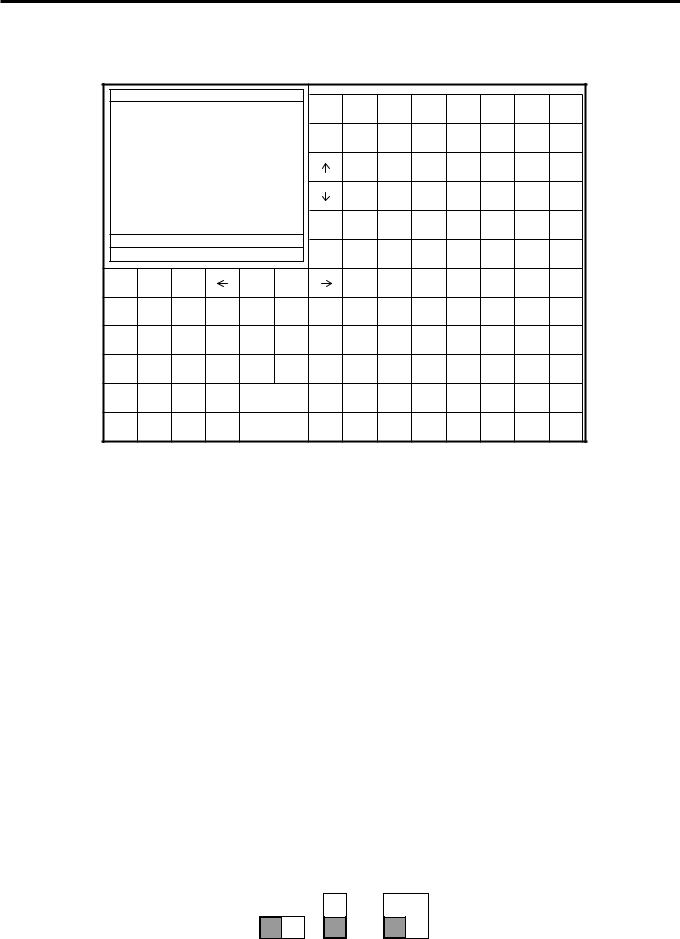
1-4. Display
1-4-1. Main display part
1 Main display part: Used for displaying numeric entries, registration, subtotal amount, etc.
2 Menu level display part: Used for displaying the current shift PLU, menu sheet and 2nd unit price level. 3 Keyboard part: Mainly used for keyboard (sometimes it is used for pop-up window)
REG |
C01 |
31-10-08 |
12:34 PM 001234 |
|
|
2 |
|
|
|
|
|
||||
|
|
|
|
|
|
|
|
HOME |
PLU010 |
PLU020 |
PLU030 |
PLU040 |
PLU050 |
PLU060 |
PLU070 |
|
|
|
|
|
|
|
|
PAGE |
PLU009 |
PLU019 |
PLU029 |
PLU039 |
PLU049 |
PLU059 |
PLU069 |
|
|
|
|
|
|
|
|
UP |
|||||||
|
|
|
1 |
|
|
|
|
|
PLU008 |
PLU018 |
PLU028 |
PLU038 |
PLU048 |
PLU058 |
PLU068 |
|
|
|
|
|
|
|
|
|
|
|
|
|
|
|
|
|
|
|
|
|
|
|
|
|
PLU007 |
PLU017 |
PLU027 |
PLU037 |
PLU047 |
PLU057 |
PLU067 |
|
|
|
|
|
|
|
|
PAGE |
PLU006 |
PLU016 |
PLU026 |
PLU036 |
PLU046 |
PLU056 |
PLU066 |
|
|
|
|
|
|
|
|
DOWN |
|||||||
|
|
|
|
|
|
•0.00 |
|
|
|
|
|
|
|
||
|
|
|
|
|
|
END |
|
|
|
|
|
|
|
||
|
|
|
|
|
|
|
|
PLU005 |
PLU015 |
PLU025 |
PLU035 |
PLU045 |
PLU055 |
PLU065 |
|
ESC/ |
|
MODE |
SEARCH |
|
|
YES |
NO3 |
PLU004 |
PLU014 |
PLU024 |
PLU034 |
PLU044 |
PLU054 |
PLU064 |
|
SKIP |
|
|
|
||||||||||||
|
CLEAR |
X |
VOID |
||||||||||||
CLK# |
|
#/NS |
COVERS |
MENU |
PLU003 |
PLU013 |
PLU023 |
PLU033 |
PLU043 |
PLU053 |
PLU063 |
||||
RECEIPT |
7 |
8 |
9 |
|
SEAT# |
POST |
SEP |
PLU002 |
PLU012 |
PLU022 |
PLU032 |
PLU042 |
PLU052 |
PLU062 |
|
|
ENTRY |
CHK |
|||||||||||||
TABLE |
|
4 |
5 |
6 |
|
FUNC |
FIN. |
TBL |
PLU001 |
PLU011 |
PLU021 |
PLU031 |
PLU041 |
PLU051 |
PLU061 |
RECEIPT |
|
|
LIST |
LIST |
TRANS |
||||||||||
PLU# |
|
1 |
2 |
3 |
|
SUBTOTAL |
NB |
LIST |
LIST |
LIST |
LIST |
LIST |
LIST |
LIST |
|
|
|
|
1 |
2 |
3 |
4 |
5 |
6 |
7 |
||||||
REPORTS |
0 |
00 |
• |
|
CASH/AMT |
NEW/OLD |
MENU |
MENU |
MENU |
MENU |
MENU |
MENU |
MENU |
||
|
|
/TEND |
CHK |
1 |
2 |
3 |
4 |
5 |
6 |
7 |
|||||
1-4-2. Main display part contents
Mode Clerk |
Date |
Time |
Consecutive number |
|
REG |
C01 |
01-01-01 12:34 |
001234 |
|
|
1 |
Spagetti |
|
•20.00 T1 |
↑ |
|
1 |
Spagetti |
|
•20.00 T1 |
|
|
|
7.5% |
|
|
|
|
|
%- |
|
-1.75 T1 |
|
|
1 |
Coffee |
|
•8.00 |
|
|
1 |
Hamburger |
|
•2.00 T1 |
|
|
|
15% |
|
|
|
|
|
%- |
|
-0.30 T1 |
|
|
1 |
Milk |
|
•2.00 |
|
|
2 |
Apple Juice |
•5.00 |
||
|
1 |
Coffee |
|
•8.00 ↓ |
|
Spagetti |
|
•20.00 |
§ ©ª 12 |
•76.50 |
|
|
|
|
Status Icons |
Items sold |
Total amount |
• Communication: § |
• Receipt on: © |
|
• Master/BM error: ¶ |
• Character shift: |
|
• Cut off Master or BM: ß |
Double size: ª |
|
|
Standard size: π |
|
Scroll area
Current transaction amount/change
QT-6600 Reference Manual |
R-13 |
Hardware Configuration
1-4-3. Menu level display part contents
|
|
SHIFT PLU 1 |
|
|
|
Menu shift 1 |
|
|
|
|
|
2nd@ |
|
|
||
|
|
|
|
|
|
|
|
|
|
|
|
|
|
|
|
|
|
|
Shift PLU level (1 ~ 8) |
|
|
Menu shift (1 ~ 15) |
|
|
|
2nd unit Price level (1 ~ 2) |
|||||||
1-4-4. Main display brightness control
LAN
DISPLAY |
SCANNER |
COM3 |
COM2 |
COM6 |
COM5 |
PC/MODEM
COM1
COM4
Brightness control
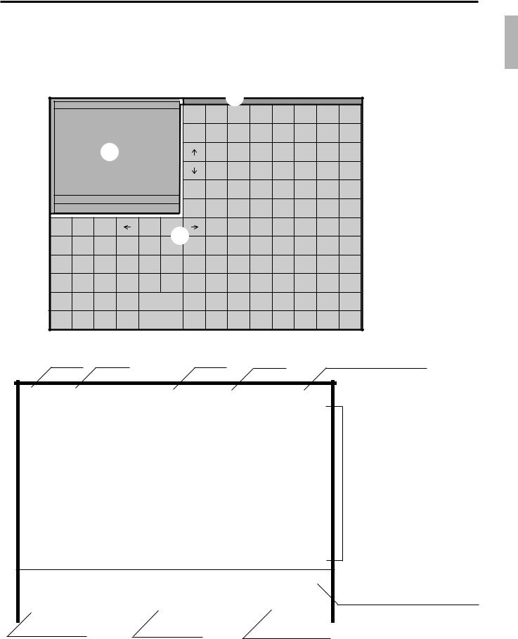
1-5. Cash drawer
In case of connecting drawer, follow the procedure below.
Connect the drawer.
1.Connect drawer connector (three color lead on drawer) to the terminal.
2.Connect frame drawer connector (green lead on drawer) to the terminal.
Mount the cash register.
1.Attach 2 positioning screws bottom side of the terminal.
2.Mount the terminal on the top of the drawer, ensuring that the feet on the bottom of the terminal go into the holes on the drawer.
R-14
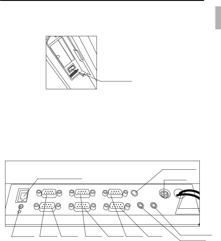
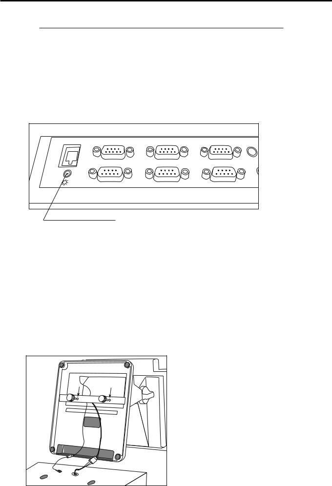
1-6. Input/output connectors Power switch
Main power switch is located in the power switch cover.
Power switch
Input /output connectors
Inline connector, COM port, and drawer cable are located in the bottom side connector cover.
Bottom side of the terminal
Inline (10/100Base-T)
LAN |
DISPLAY |
SCANNER |
|
||
|
COM3 |
COM2 |
|
COM6 |
COM5 |
Brightness COM3 COM6 COM2
PC/MODEM |
PS/2 |
|
|
|
|
|
KEYBOARD |
|
COM1 |
|
|
COM4 |
SPK |
MIC |
|
|
|
COM5 COM1 COM4
PS/2 Keyboard
AC Adaptor
Drawer 2
Drawer 1
Ext. microphone
Ext. speaker
QT-6600 Reference Manual |
R-15 |

Hardware Configuration
1-7. Optional peripherals
The following optional peripherals can be used by plugging them into the appropriate port.
1)Personal computer / MODEM: RS-232C COM 1 port
2)Scanner: RS-232C COM 2 port Hand-held scanner, Fixed scanner
3)Slip printer: RS-232C COM 2 port SP-1300
In case of installing both scanner and slip printer, connect slip to COM 4, 5 port.
If you connect the slip printer to COM 4 , the automatic detection during INIT does not performed. You muse program the I/O parameter manually.
4)Remote display: RS-232C COM 3 port QT-6060D
5)Remote printer (UP-400/360): RS-232C COM 4 ~ 6 port The remote printer is used for reports/kitchen orders/receipts.
6)Inline: Inline port
You can use CAT5 UTP cable. 7 Drawer: drawer port
8)CF card: CF card slot (in the power switch cover)
9)PS-2 keyboard (Microsoft Wired Keyboard RT2300): PS-2 keyboard port
R-16
1-8. System configuration
This section represents the system configuration of the QT-6600. The QT-6600 have four different system configurations, such as 1. Shared check tracking/ floating clerk interrupt system, 2. Inline collection/ consolidation system, 3. Online collection/ consolidation system, and 4. Online collection/ consolidation system (use FTP feature).
Before detail explanation, we should define the words:
1)Check master:
Check master is the master server of shared check tracking system and floating clerk interrupt system. This terminal has check index and detail files and controls them.
2)Check backup master:
Check backup master is the backup server of shared check tracking system and floating clerk interrupt system. This terminal also has check index and detail files and update them at the same timing of master.
When the check master goes down, the backup master plays the role of check master.
3)Check self master:
Check self master has its check tracking system files and clerk interrupt files for itself.
4)Satellite:
The terminal which is not assigned to 1) ~ 3) above.
5)Remote printer (via RS-232C or LAN):
Remote printer prints data sent from both its own terminal and other terminal of the system.
6)Local printer:
Local printer prints data sent from its own terminal.
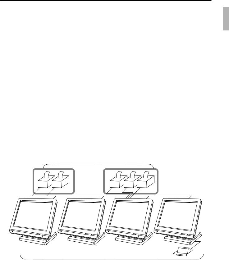
1-9-1. Shared check tracking system/floating clerk interrupt system
System Recommendation
Up to 16 remote printers
LAN Printer RS-232C Printer
Order |
Order |
Order |
Order |
Order |
PRN (1) |
PRN (2) |
PRN (1) |
PRN (2) |
PRN(3) |
inline
C |
C |
C |
C |
CHK/BM  CHK/M
CHK/M
Slip
Up to 12 QT-6600 terminals
QT-6600 Reference Manual |
R-17 |
Hardware Configuration
Available peripherals versus ECR definition
: Available
|
|
Peripherals |
||
|
|
|
|
|
ECR definition |
Remote |
|
Slip |
PC/ |
|
printer |
|
printer |
MODEM |
|
|
|
|
|
Check master |
|
|
|
|
|
|
|
|
|
Check backup master |
|
|
|
|
|
|
|
|
|
Self master |
|
|
|
|
|
|
|
|
|
Satellite |
|
|
|
|
|
|
|
|
|
Available combinations ECR definition
: Available
|
Check |
Check |
Self |
Terminal |
ECR definition |
master |
backup |
master |
w/ remote |
|
|
master |
|
printer |
|
|
|
|
|
Check master |
|
× |
× |
|
Check backup master |
× |
|
× |
|
Self master |
× |
× |
|
|
Terminal w/ remote printer |
|
|
|
|
|
|
|
|
|
Note:
1)Please follow the system recommendation above. Otherwise the system performance may be slow down.
R-18
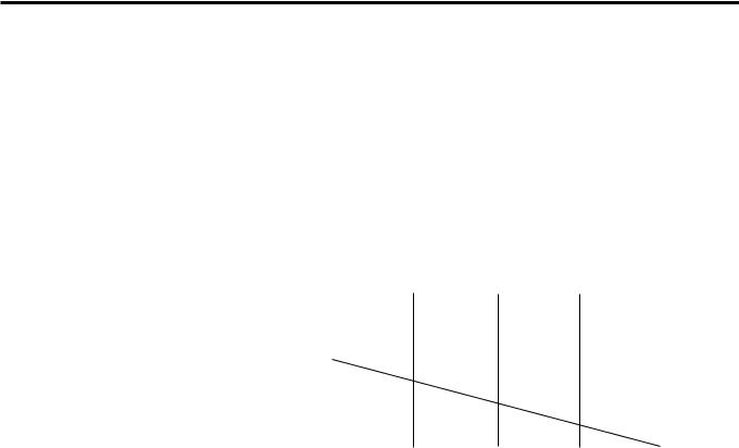
1-8-2. Inline collection/consolidation system
• Inline collection/consolidation and auto-programming for up to 32 terminals.
PC
Via COM 1 port of the master terminal or Inline
C |
C |
C |
C |
C |
Maximum 32 terminals
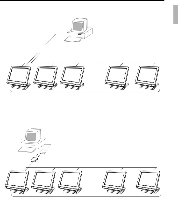
1-8-3. Online collection / consolidation system
• Online collection / consolidation and auto-programming for up to 32 terminals.
PC
on-line (Public / Private Telephone line)
C |
C |
C |
C |
C |
Maximum 32 terminals
QT-6600 Reference Manual |
R-19 |
Hardware Configuration
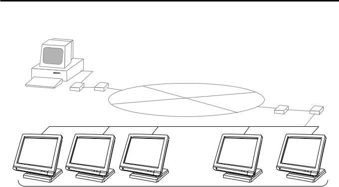
1-8-4. Online collection / consolidation system (use FTP feature)
• Online collection / consolidation and auto-programming for up to 32 terminals.
|
|
ADSL/FTTH |
|
PC |
|
MODEM |
|
|
VPN router |
Internet |
ADSL/FTTH |
|
|
||
|
|
MODEM VPN router |
|
|
|
|
C |
C |
C |
C |
C |
Maximum 32 terminals
R-20
2. |
Application systems ............................................................................ |
R-23 |
|
|
2-1. General description of application system ....................................... |
R-23 |
|
||
2-1-1. |
File concept................................................................................................... |
R-23 |
|
|
2-1-2. |
Linkage of totalizers ...................................................................................... |
R-24 |
|
|
|
||||
2-1-3. |
Function keys ................................................................................................ |
R-25 |
|
|
2-1-4. |
Keyboard layout ............................................................................................ |
R-25 |
|
|
2-1-5. |
Mode control ................................................................................................. |
R-26 |
|
|
2-1-6. |
Operation prompt and error messages ......................................................... |
R-26 |
|
|
|
||||
2-1-7. |
Printing control system.................................................................................. |
R-26 |
|
|
2-2. General description of individual function keys ............................... |
R-29 |
|
||
2-2-1. |
System keys .................................................................................................. |
R-29 |
|
|
2-2-2. |
Finalize keys ................................................................................................. |
R-30 |
|
|
2-2-3. |
Transaction keys ........................................................................................... |
R-30 |
|
|
2-3. |
Remote printer control ........................................................................ |
R-39 |
|
|
2-3-1. |
Remote printer system configuration ............................................................ |
R-39 |
|
|
2-3-2. |
Remote printer control setting ....................................................................... |
R-40 |
|
|
2-3-3. |
Remote printer output control ....................................................................... |
R-41 |
|
|
2-3-4. |
Remote printer backup processes ................................................................ |
R-41 |
|
|
2-4. |
Check tracking system ........................................................................ |
R-44 |
|
|
2-4-1. |
Shared check tracking system ...................................................................... |
R-44 |
|
|
2-4-2. |
Shared check tracking requirement .............................................................. |
R-45 |
|
|
2-4-3. |
Data backup when the master goes down .................................................... |
R-45 |
|
|
2-5. Other check tracking system control ................................................. |
R-46 |
|
||
2-5-1. |
The timing to clear check detail and index file after finalization .................... |
R-46 |
|
|
2-5-2. |
Table transfer ................................................................................................ |
R-46 |
|
|
2-5-3. |
Store and recall ............................................................................................. |
R-46 |
|
|
2-6. |
Clerk control function ......................................................................... |
R-48 |
|
|
2-6-1. |
Clerk interrupt ............................................................................................... |
R-48 |
|
|
2-6-2. |
Clerk detail memory ...................................................................................... |
R-49 |
|
|
2-6-3. |
Clerk training ................................................................................................. |
R-49 |
|
|
2-6-4. |
Manager mode control .................................................................................. |
R-49 |
|
|
2-7. Arrangement key function and scheduler ......................................... |
R-51 |
|
||
2-7-1. |
Arrangement key function ............................................................................. |
R-51 |
|
|
2-7-2. |
Arrangement program example .................................................................... |
R-55 |
|
|
2-7-3. |
Scheduled execution of arrangement function .............................................. |
R-55 |
|
|
2-8. |
Making graphic logo ............................................................................ |
R-56 |
|
|
2-8-1. |
About graphic logo ........................................................................................ |
R-56 |
|
|
2-8-2. |
Making graphic logo procedure ..................................................................... |
R-56 |
|
|
2-9. |
Hourly item ........................................................................................... |
R-57 |
|
|
2-9-1. |
Programming necessary files before using hourly item function................... |
R-57 |
|
|
2-10. Time and attendance ........................................................................... |
R-58 |
|
||
2-10-1. |
Corresponding relations of the file ................................................................ |
R-59 |
|
|
2-10-2. |
Clock-in operation ......................................................................................... |
R-62 |
|
|
2-10-3. |
Clock-out operation ....................................................................................... |
R-65 |
|
|
QT-6600 Reference Manual |
R-21 |

Application System
2-11. Sign on control .................................................................................... |
R-68 |
|
2-11-1. |
Sign on .......................................................................................................... |
R-68 |
2-11-2. Solution to abnormality of master terminal ................................................... |
R-69 |
|
2-11-3. Solution to abnormality of satellite terminal .................................................. |
R-69 |
|
2-11-4. |
Sign on compulsory ...................................................................................... |
R-69 |
2-12. IDC (Item Data Capture) ...................................................................... |
R-70 |
|
2-12-1. |
Available capturing items .............................................................................. |
R-70 |
2-12-2. Set up the IDC start / end ............................................................................. |
R-73 |
|
2-12-3. How to memorize the captured items ........................................................... |
R-74 |
|
2-12-4. IDC data file structure ................................................................................... |
R-75 |
|
2-12-5. |
IDC data type ................................................................................................ |
R-81 |
2-12-6. |
Transferring IDC ............................................................................................ |
R-82 |
2-13. Electronic journal ................................................................................ |
R-83 |
|
2-13-1. |
Storing electronic journal .............................................................................. |
R-83 |
2-13-2. Issuing electronic journal report .................................................................... |
R-83 |
|
2-13-3. Displaying normal electronic journal and producing guest receipts after sales .......... |
R-83 |
|
2-13-4. Transferring electronic journal memory ......................................................... |
R-84 |
|
2-14. Simple time and attendance ............................................................... |
R-85 |
|
2-14-1. |
Clock-in operation ......................................................................................... |
R-85 |
2-14-2. |
Clock-out operation ....................................................................................... |
R-86 |
2-14-3. |
Worktime display ........................................................................................... |
R-86 |
2-14-4. Report ........................................................................................................... |
R-86 |
|
2-15. Magnetic card reading ......................................................................... |
R-87 |
|
R-22

2.Application systems
This section describes the configuration of application system and their related setting with the QT-6600. Reading this section provides a general understanding of the overall system of the terminal.
2-1. General description of application system
2-1-1. File concept
Programming data for each function, as well as registration data, are assigned and handled in the RAM of the terminal in data blocks called files. Each files identified by a 3-digit file number consists of multiple records.
Memory management on a file basis allows flexibility memory allocation in accordance with the application of a specific terminal. The number of records per file can be programmed, and a file can even be programmed for zero records.
There are three types of files:
–Terminal files:
Terminal files include system work files, daily total files, periodic total 1, periodic total 2 files, buffer files, and program files. Periodic total files have only totalizer field, and totalize the same data which is accumulated to terminal files at the same time. The periodic total 1 files have 100 order file numbers, and the periodic total 2 files have 200 order file numbers.
These files can be reset individually and separately from the terminal files. This provides access to weekly and monthly total data. The periodic total 1 files and 2 files have the same functions, and can accumulate data with different periods. The same number of records as the corresponding terminal file must be reserved for each periodic total files.
–Consolidation files:
Consolidation files are work files for consolidation of daily total, periodic 1 total and periodic 2 total data from each terminal, and have 300, 400 and 500 order file numbers, respectively. The same number of records as the corresponding terminal files must be reserved for each file, on the master terminal.
–Consolidation work files:
Consolidation work files are work files for collection/consolidation of daily, periodic 1/2 data from each terminal. The files have 600 order file numbers.
The file number of records as the corresponding terminal file must be reserved for each consolidation file.
Each file requires an internal work area, so calculation of actual file size can be performed using the following formula:
Record length × Number of records + Work area = Actual file size
The table on the page 18 ~ 22 of the programming manual shows all the files available for the terminal. See the Appendix A-2 of this manual for detail formats of individual files.
QT-6600 Reference Manual |
R-23 |
Application System
2-1-2. Linkage of totalizers
Registered data is accumulated to totalizers which are reserved for each functions.
The QT-6600 has the following types of totalizers:
1)Fixed totalizers
Registration data is accumulated for individual terminals.
2)Function key totalizers
Data input by finalize or transaction keys is accumulated in totalizers for each key. Operation types, as well as data used in operation differ depending on the key.
3)Subdepartment totalizers
Registration data is accumulated in totalizers for each subdepartment.
4)Department totalizers
Registration data is accumulated in totalizers for each department.
5)Group totalizers
Registration data is accumulated in totalizers for each group.
6)PLU/ scanning PLU totalizers
Registration data is accumulated in totalizers for each PLU/ scanning PLU.
7)Clerk totalizers
Registration data is accumulated for each relevant clerk. A clerk detail totalizer can be linked to a fix totalizer, finalize key, transaction key, or item totalizer (department / PLU / subdepartment / group), and accumulate data registered for the destination totalizer of each relevant clerk.
8)Other totalizer
Functions for hourly sales, monthly sales void reason, table analysis, time attendance and hourly item etc. also have totalizers.
Registration data flow
Registration
Calculation
*2
*1 |
*1 |
*1 |
Fixed totalizer |
|
|
Function key |
|
|
PLU file |
|
|
Subdept. file |
|
|
Dept. file |
|
|
Group file |
|
Clerk detail file |
|
|
Other file |
||||||||
|
|
|
totalizer |
|
Scanning PLU file |
|
|
|
|
|
|
|
|
|
|
|
|
|
|
|
|
|
|
|
|
|||
|
|
|
|
|
|
|
|
|
|
|
|
|
|
|
|
|
|
|
|
|
|
|
|
|
|
|
|
|
|
|
|
|
|
|
|
|
|
|
|
|
|
|
|
|
|
|
|
|
|
|
|
|
|
|
|
|
|
|
|
|
|
|
|
|
|
|
|
|
|
|
|
|
|
|
|
|
|
|
|
|
|
|
|
|
|
|
|
|
|
|
|
|
|
|
|
|
|
|
|
|
|
|
|
|
|
|
|
|
|
|
|
|
|
|
|
|
|
|
|
|
|
|
|
|
|
|
|
|
|
|
|
|
|
|
|
|
|
|
|
|
|
|
|
|
|
|
|
|
|
|
|
|
|
|
|
|
|
|
|
|
|
|
|
|
|
|
|
|
|
|
|
|
|
|
|
|
|
|
|
|
|
|
|
|
|
|
|
|
|
|
|
|
|
|
|
|
|
|
|
|
|
|
|
|
|
|
|
|
|
|
|
|
|
|
|
|
|
|
|
|
|
|
|
|
|
|
|
|
|
|
|
|
|
|
|
|
|
|
|
|
|
|
|
|
|
|
|
|
|
|
|
|
|
|
|
|
|
|
|
|
|
|
|
|
|
|
|
|
|
|
|
|
|
|
|
|
|
|
|
|
|
|
|
|
|
|
|
|
|
|
|
|
|
|
|
|
|
|
|
|
|
|
|
|
|
|
|
|
|
|
|
|
|
|
|
|
|
|
*1
*2
Linking between PLUs/ scanning PLUs, subdepartments, departments and groups can be programmed to meet the needs of the retail environment.
PLUs/ scanning PLUs can be programmed to link with subdepartments, departments or group, while subdepartment can be programmed to link with department or group, and department can be programmed to link with group.
When a PLU is programmed to link with a department, data registered for the PLU is also accumulated to the department. In addition, when the department is programmed to link with a group, data registered for the PLU is simultaneously reflected the department totalizer and group totalizer.
When data is registered to a totalizer which is preset in the clerk detail link table, the data is also accumulated to the clerk detail totalizer reserved for each relevant clerk.
R-24

2-1-3. Function keys
The keys on the keyboard can be assigned various functions that are used for registration as required for the terminal. For convenience sake, these functions are called by function keys.
There are two types of function keys:
1)System keys
Numeric keys, clear key, home position key, end key, left / right / up / down arrow keys, yes key, no key, mode selection keys, ESC/SKIP key, page up / down key are system keys.
2)Function keys
These function keys are used for finalize a transaction, to specify the functions for a registration or to specify the meaning of a entry. These function keys have programmable functions, which are set to the transaction key / department / subdepartment / PLU file.
Function keys include finalize key, transaction key, department key, subdepartment key and flat PLU key.
The list of all function keys is shown in the Program 4 chapter of the programming manual. General descriptions of individual function keys are found in the chapter 2-2.
2-1-4. Keyboard layout
Normally, the keyboard is assigned functions which are required for registration of transactions. The keyboard is also used for character input when entering descriptors or names during programming.
The QT-6600 automatically switches the keyboard to its character input function when it determines that character input is required for the operation sequence you are performing. This means that you can input characters without having to worry about manually changing the keyboard input mode.
The function key (except system keys) allocation is fully programmable to meet the specific needs of each terminal. The actual programming of key layouts can be performed in the PGM4 mode, and programmed data is written onto the key table (file 074/174).
The allocation can also be programmed when programming each function file for programming function keys such as finalize keys, transaction keys, department keys, subdepartment keys, and flat PLU keys.
Standard function key layout
Refer to the page 16 of the user’s manual.
Character key layout
Refer to the page 126, 127 of the programming manual.
QT-6600 Reference Manual |
R-25 |

Application System
2-1-5. Mode control
With the QT-6600, each clerk can be programmed to enable or disable operations in the following modes:
–REF mode
–REG– mode
–REG mode
–X/Z mode
–Program 1 ~ 6 mode
–Manager mode
–Inline X/Z mode
–Inline auto program
–CF backup / restore mode
Also, each clerk can be programmed to enable or disable operations of every function key. Though the terminal has no actual REG 2 mode, on the page 49 in the Clerk Control function chapter of this manual, the manager control procedure is described.
Arrangement execution mode programmed in the arrangement key ignores the mode control program by the clerk.
Please note that if a clerk want to operate an arrangement, he / she should allow to operate arrangement function.
2-1-6. Operation prompt and error messages
The QT-6600 displays messages to indicate the status of the terminal being operated or programmed. These messages help to determine the status of the terminal or the required subsequent action.
2-1-6-1. Operation prompt
Refer to the page 231 of this manual for details. These messages cannot be added, modified or deleted.
2-1-6-2. Error messages
Refer to the page 228 ~ 231 of this manual for details. Error messages are displayed to indicate that an error has occurred and a compulsory operation must be performed. All error messages cannot be added, modified or deleted.
2-1-7. Printing control system
The following describes the control system for printing of receipts, the journal, validation, slips and X/Z reports.
2-1-7-1. Receipt print control during normal registration
Normally, the receipt is printed to reflect the details of a registration as it is performed, with the receipt being issued with the finalize operation. By using the <RECEIPT ON/OFF> key, the receipt issuance status can be turned off to suspend printing and issuance of receipts when so desired. Pressing the <RECEIPT ON/OFF> key turns the receipt issuance status on or off, and when the receipt issuance status is On, the icon “RECEIPT ON” appears.
The following programming can be performed for receipt printing:
R-26

Description |
Program location |
|
|
Receipt “Item consolidation” |
PGM3; Machine Control3 in General Feature |
|
|
Receipt “Sort by group, department” |
PGM3; Machine Control3 in General Feature |
|
|
Print consecutive number on the receipt |
PGM3; Machine Control3 in General Feature |
|
|
Print date / time on the receipt |
PGM3; Machine Control3 in General Feature |
|
|
Vertical double character |
PGM3; Machine Control3 in General Feature |
|
|
Set menu detail on guest / slip |
PGM3; Print Control in General Feature |
|
|
Print PLU number |
PGM3; Print Control in General Feature |
|
|
Print finalized total |
PGM3; Print Control in General Feature |
|
|
Print taxable amount |
PGM3; Print Control in General Feature |
|
|
Print taxable status |
PGM3; Print Control in General Feature |
|
|
Print total number of item sold |
PGM3; Print Control in General Feature |
|
|
Print customer number (number of covers) |
PGM3; Print Control in General Feature |
|
|
One line feed after finalization |
PGM3; Print Control in General Feature |
|
|
Time format (24H / 12H) |
PGM3; Print Control in General Feature |
|
|
|
|
|
|
2-1-7-2. Validation print control
The QT-6600 allows use of the slip printer (SP-1300) for validation printing of item registrations, function registrations and sales totals. To perform validation printing, insert the validation paper into the slip printer, and then press the <VALIDATION> key (function code 037).
The following desctription shows the print format for validation performed using the slip printer.
There are three general types of validation printing:
1)Finalization validation
2)Transaction validation
3)Item validation
Finalization validation is performed following finalization operations with finalize keys. When a validation is performed following receipt issuance, the sales total or tendered amount is printed, while partial tendering, the tendered amount for the specified medium is printed.
Transaction validation is valid for the following function keys:
–Received on account, Paid out, finalization of Pick up or Loan, Check cashing, Minus, Plus, Discount, Premium, Void, Coupon, Coupon2, Tip, Deposit, Subtotal, Merchandise subtotal keys
You can program the allowable number of validation printings or multiple validation printing status for the above listed keys.
Also some of these keys can be programmed as validation compulsory, this means that registration is not permitted until the validation of the former registration has been performed.
Item validation is performed directly following an item registration listed below.
–Departments
–Subdepartments
–PLUs/ scanning PLUs
You can program the multiple validation printing status for above items.
QT-6600 Reference Manual |
R-27 |

Application System
2-1-7-3. Slip print control
Connection of an optional slip printer (SP-1300) to the QT-6600 makes it possible to print transaction details on a slip.
To print a slip, insert a slip paper into the printer, and adjust paper position by entering the number of printed lines and pressing the <SLIP FEED/RELEASE> key (function code 056) or the <SLIP BACK FEED/RELEASE> key (function code 054) and then press the <SLIP PRINT> key (function code 055). Or it is possible to find the appropriate slip printing start line automatically.
After printing a slip, the paper is automatically released.
If the paper is not released for some reasons, press <SLIP FEED/RELEASE> or <SLIP BACK FEED/RELEASE> to release the paper.
Before using slip printer, you should program the maximum lines of slip.
The following two sections are other features to control slip printing format:
2-1-7-4. Endorsement message print control
The QT-6600 allows printing of endorsement messages on the slip printer (SP-1300) for check registrations. To perform endorsement message printing, insert the paper into the slip printer following finalization using the <CHECK> key or check cashing transaction using the <CHECK> key, and press the following key:
– Endorsement key (function code 039)
Check key and check cashing key can be programmed for compulsory endorsement print. The endorsement message contents should be programmed into the endorsement message file (file 033).
2-1-7-5. Check printing print control
The QT-6600 allows printing check tendered amount on a check inserted into the slip printer. To perform check printing, insert the paper into the slip printer following check finalization using the <CHECK> key, and press the following key:
– Check print key (function code 012)
Check key can be programmed for compulsory check print. The check printing format is controlled by the check print file (file 041).
2-1-7-6. X/Z report print control
The QT-6600 can output a report in the read (X) or reset (Z) mode. The following shows the programming for X/Z print controls:
Description |
Program location |
|
|
Items on the fixed totalizer report |
PGM3; Report Control1 in General Feature |
Items zero skip |
PGM3; Report Control2 in General Feature |
Average spend/item on monthly report |
PGM3; Report Control2 in General Feature |
PLU order (memory / random code) |
PGM3; Report Control2 in General Feature |
Print / Non print PLU No. on PLU report |
PGM3; Report Control2 in General Feature |
Print / Non print Sales ratio |
PGM3; Report Control2 in General Feature |
Print / Non print Z counter |
PGM3; Report Control2 in General Feature |
Print / Non print Item discount totalizer |
PGM3; Report Control2 in General Feature |
Print GT |
PGM3; Report Control2 in General Feature |
R-28

2-2. General description of individual function keys
This section describes individual function key that can be assigned to the keys on the keyboard of QT-6600.
2-2-1. System keys
The system key consist on a non-programmable function key.
The following system keys are available.
1)Numeric keys (0, 1 ~ 9, 00, decimal point*)
These keys are used for inputting numerical data such as PLU codes, amounts, quantities, etc. These keys must be allocated on the keyboard.
2)Clear key
This key is used for clearing numerical values after they have been input, and after incorrect function keys have been pressed. This key also can be used to clear errors. This key must be allocated on the keyboard.
3)Home position key*
This key is used for returning cursor to the home position.
4)End key*
This key is used for moving cursor to the bottom position.
5)Left, right, up, down arrow keys
These keys are used for moving the cursor.
6)Yes key
This key is used for consenting the selection and proceeding steps.
7)No key
This key is used for cancelling the selection and proceeding steps.
8)Mode key
This key is used for changing modes of the terminal. This key shows the allowable mode keys in the mode pop-up window.
9)ESC/SKIP key
This key is used for terminating a programming sequence, X/Z sequence, and returning the former window. This key is also used for terminating a report being issued in PGM, X, and
Zmode.
10)Display on/off key
This key is used for turning on / off the terminal.
11) Page up key*
This key is used for turning the window forwards.
12) Page down key*
This key is used for turning the window backwards. * Allocatable key
QT-6600 Reference Manual |
R-29 |

Application System
2-2-2. Finalize keys
This section covers the general description of each finalize key, with its respective options. Finalize keys have programmable functions which may be used as required.
1)Tender key
This key is used for finalizing transactions. Up to six media in drawer totalizers are reserved in the fixed totalizer file, and cash key is linked to cash in drawer, charge key to charge in drawer, check key to check in drawer and credit key to credit in drawer, food stamp tender key to food stamp in drawer, EBT tender key to EBT in drawer.
When this key is pressed, the total amount of the transaction is calculated. Normally, a receipt is issued and the drawer opens at the same time. The total amount is added to the appropriate totalizers and counters, with consecutive numbers being increased by one. When an amount exceeding the sales amount is received, the change is calculated, displayed and printed on the receipt.
This key can also be used in combination with other finalize keys for partial tender and can also be used to specify the type of media during loan, pick up or media change operation. Programmability: Refer to page 94, 96 of the programming manual.
2)New balance key
This key is used for adding the latest registered total amount to the previous balance to obtain a new balance.
When this key is pressed, the total amount of the transaction is calculated. Normally, a receipt is issued.
Programmability: Refer to page 95 of the programming manual.
2-2-3. Transaction keys
Each of the transaction keys have programmable functions which may be used as required. The general description of each transaction key, with individual options, is outlined on the following sections.
1)Price inquiry key (Function code 008)
This key is used to confirm the price and descriptors of PLU without registering.
2)Stock inquiry key (Function code 009)
This key is used to confirm the stock quantity and descriptors of PLU without registering.
3)Text recall key (Function code 010)
This key is used to recall characters.
Programmability: Refer to page 97 of the programming manual.
4)Text print key (Function code 011)
This key is used to print the entered characters.
Programmability: Refer to page 97 of the programming manual.
5)Check print key (Function code 012)
This key is used to print the check on the slip printer (SP-1300). Pressing this key allows the selection from the following list to print on a check.
1.Check amount in Arabic numerals (normal size / double size)
2.Date (normal size / double size)
3.Check print message in the check endorsement message file
This item noted above can be arranged into a check print format according to the needs of the store. Check printing using this key is valid only for the following operation of the check key.
Programmability: Refer to page 98 of the programming manual.
6)Clerk transfer key (Function code 013)
This key is used to transfer opened checks to another clerk.
Programmability: Refer to page 98 of the programming manual.
R-30
 Loading...