

Page 1
PZ-7
(without price)
INDEX
Model-B: USA
Model-C: Europe
PORTABLE CD PLAYER
Page 2

CONTENTS
Disassembly Instructions .............................................................................................................. 1
CD Adjustment ............................................................................................................................... 2
Block Diagram ................................................................................................................................ 3
Troubleshooting ............................................................................................................................. 4
PCB Views..................................................................................................................................... 11
CD Amplifier PCB Top View ..................................................................................................... 11
CD door PCB Top View............................................................................................................11
CD AMP PCB Bottom View ...................................................................................................... 12
Wiring Diagram............................................................................................................................. 13
IC Lead Identification and Internal Diagrams............................................................................. 14
Schematic Diagrams .................................................................................................................... 21
Parts List ....................................................................................................................................... 23
Exploded Views ............................................................................................................................ 29
Cabinet..................................................................................................................................... 29
CD Mechanism......................................................................................................................... 30
Page 3
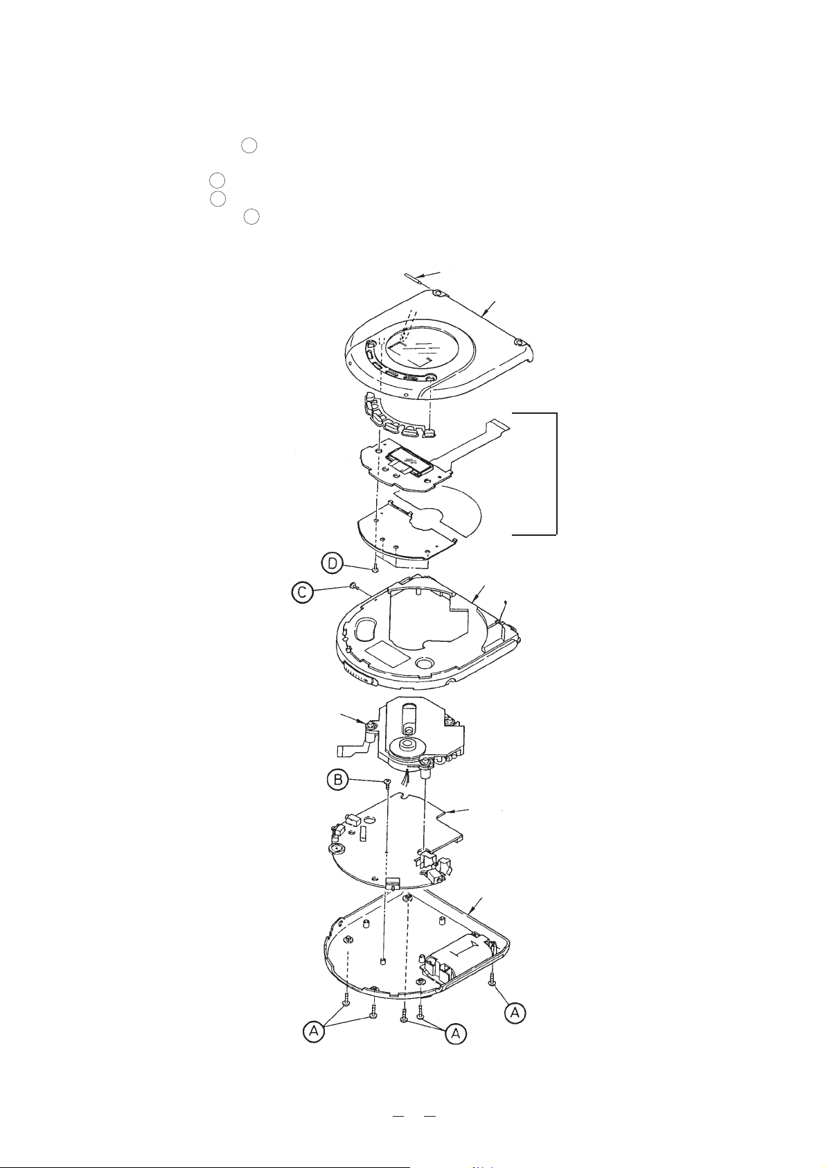
DISASSEMBLY INSTRUCTIONS
1. Remove five screws A holding the case assembly.
2. Remove the CD mechanism unit.
3. Remove screw B holding the CD AMP unit.
4. Remove screw C and pull out the shaft holding the CD door.
5. Remove four screws D holding the display PCB unit.
Shaft
CD door
Display PCB unit
CD mechanism unit
Upper case
CD AMP unit
Lower case
1
Page 4
CD ADJUSTMENT
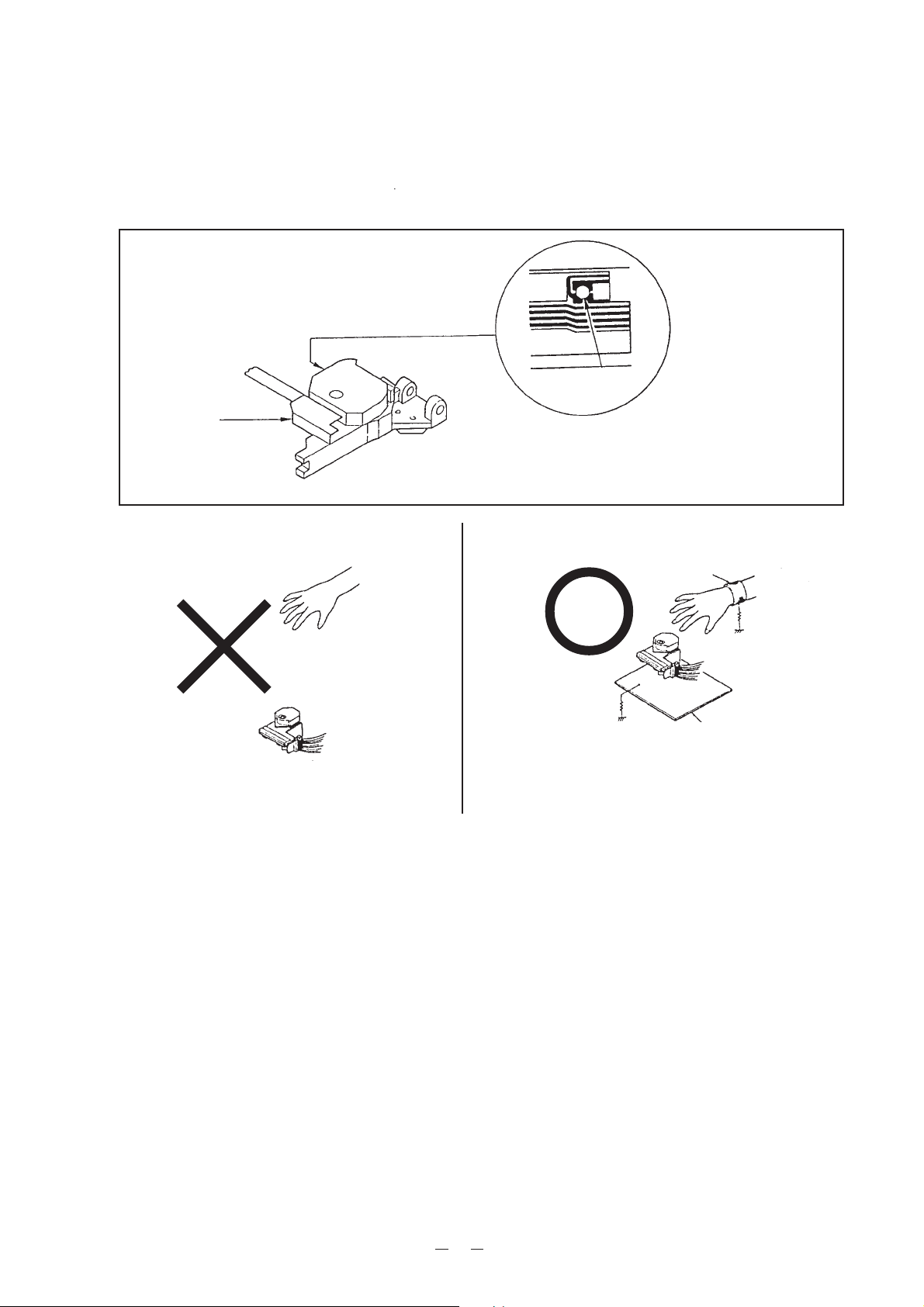
Precautions
To prevent damage caused by static electricity, the following procedures for grounding is requir or repairing
the unit.
Shorting tab
Desolder here
Pickup
[Note] Remove the connection after installed.
1. Wrist-Strap
for grounding
1MΩ
1MΩ
2. Conductive Sheet
Pickup
1. Grounding for the human body
Be sure to put on a wrist-strap for grounding (with impedance lower than 106 Ω) whose other end is
grounded. The strap works to drain away the static electricity build-up on the human body.
2. Grounding for the work table
Be sure to lay on the table a conductive sheet (with impedance lower than 106 Ω) such as a sheet of
copper which is grounded.
3. As static electricity build-up on clothes is not drainded away, be careful not to let your clothes touch the
unit.
4. The short-pad on the pick-up PCB of a spare part is short-circuited for protection during shipment. To
open the short circuit, remove the soldering quickly with a soldering iron whose insulation resistance is
larger than 10MΩ after connection to a suitable APC circuit.
Equipment Required
* Multi Meter
* Oscilloscope
* Compact Disc
* Dummy Load 10 kΩ
2
Page 5
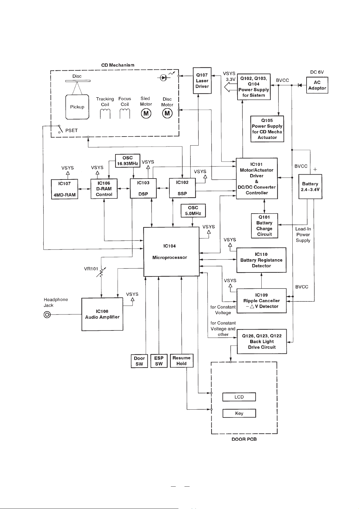
BLOCK DIAGRAM
3
Page 6
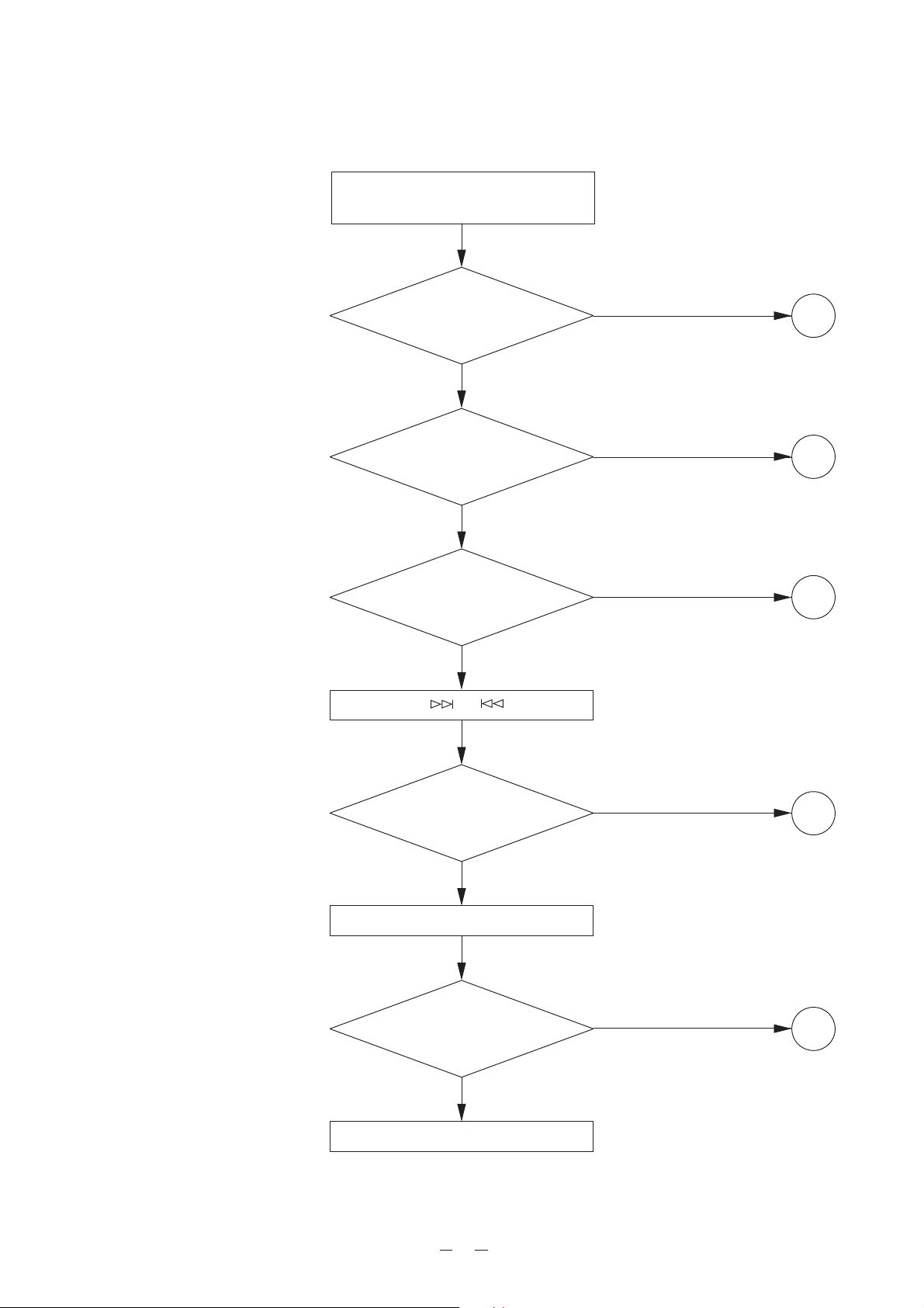
TROUBLESHOOTING
RESUME switch off and insert a disc.
Close CD door and press PLAY button.
Is “00” flashing
on LCD ?
Yes
Is “01” displayed
after “00” flashed ?
Yes
Is the audio signal
present at the output
terminals ?
Yes
Press or key.
No
1
No
2
No
3
Can a selected
track number be searched
smoothly ?
Yes
DSG switch on.
Is there any
aufio signal present at the
output terminals ?
Yes
OK
No
4
No
5
4
Page 7
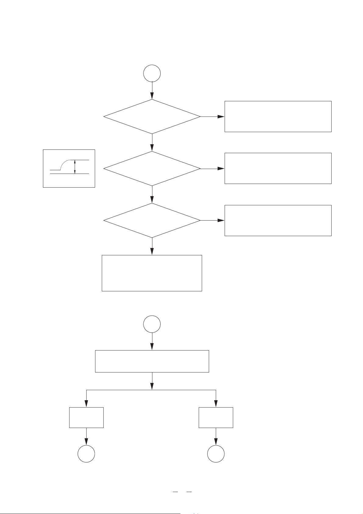
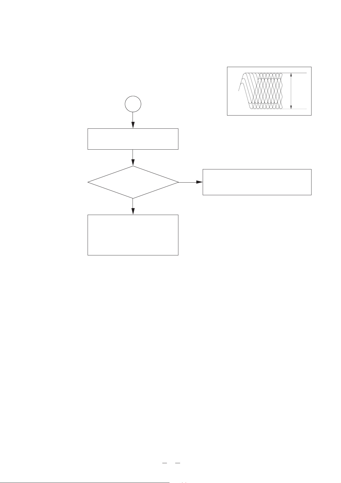
Repair Item 1: At power on, “00” is not displayed.
1
Power on
Figure 1
3.2 V
Is +3.2 V lines normal ?
Yes
Is the waveform
at IC104 pin 28 like that
shown in fig. 1 ?
Yes
Does 5 MHz clock pulse
appear at IC104 pin 29 ?
Yes
* IC104 is defective.
* Check circuit around IC104 and
CN102 for loose soldering and heat
seal connecting.
No
No
No
* RESUME switch (SW101) off position.
* Q106, Q107 or Q108 is defective.
* Check circuit around IC101 and IC104.
* IC101 is defective.
* Check circuit around IC101 and IC104.
* Crystal (X102) is defective.
* IC104 is defective.
* Check circuit around IC104 and X102.
Repair Item 2: “-- --” is displayed instead of playing first song track.
2
Check how much times it takes until “-- --”
is displayed after PLAY button is pressed.
About
14 sec
Over
14 sec
A B
5
Page 8
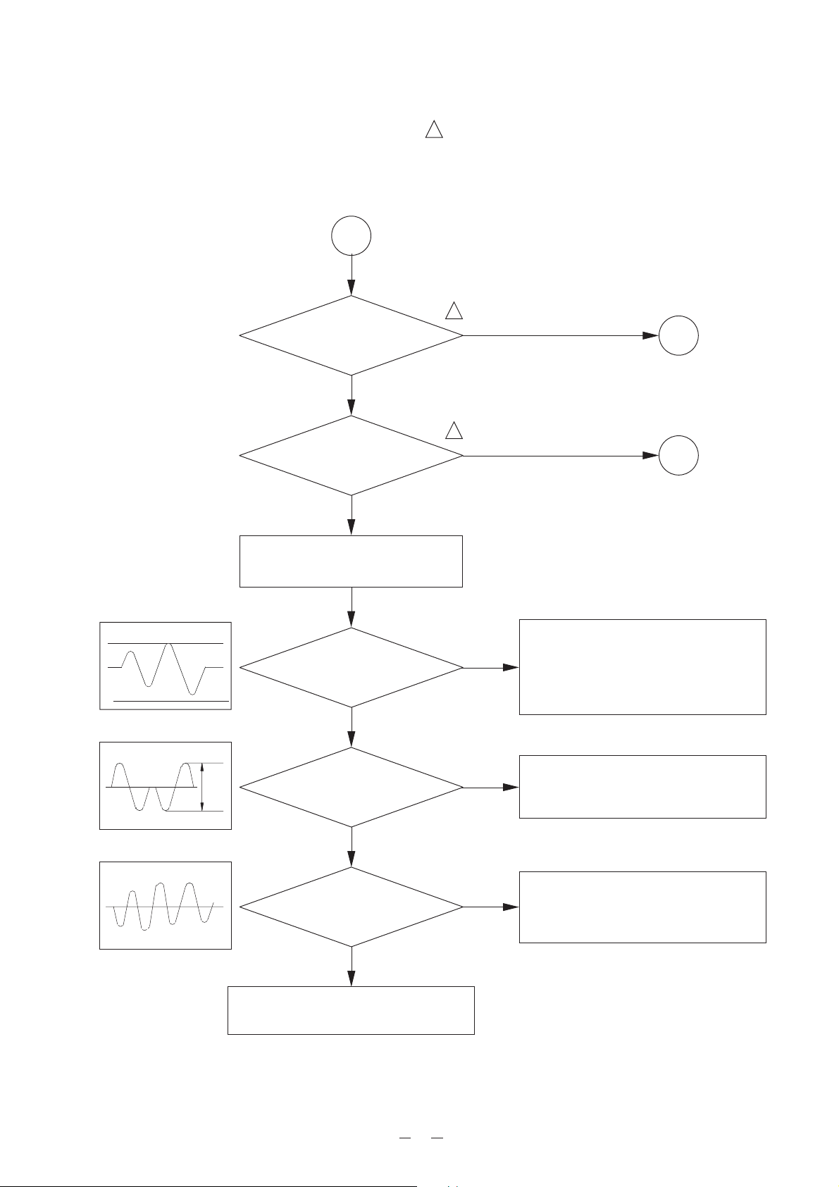
Repair Item 2-A
A
Does the LASER emit ?
Yes
Does the lens moves
up and down ?
Yes
Note: Connect GND to door switch by removing the
!
top cabinet. Than open the top cover and check the
radiation power with an optical power meter. If an
optical power meter is not available, watch the
radiation through the lens of the pickup unit at a
minimum distance of 30 cm from the pickup unit.
!
No
A1
!
No
A2
E = more than 0.9 V
Figure 2
>1.5
Figure 3
Figure 4
Load a disc and close the CD door.
Then check the following.
Is the waveform
at testpoint IRF like that
shown in fig. 2 ?
Yes
Is the waveform
at IC102 pin 1 (FEO) like that
shown in fig. 3 ?
Yes
Is the waveform
at IC102 pin 45 (TEO) like that
shown in fig. 4 ?
Yes
No
No
No
* Check flexible PCB connect.
* Check soldering for IC101, IC102 and
IC103.
* IC101, IC102 or IC103 is defective.
* Pickup is defective.
* Check circuit between IC102 pins1 and
2.
* IC102 is defective.
* Check flexible PCB connect.
* IC102 is defective.
* Check circuit around TE line.
* IC102 is defective.
* Pickup unit is defective.
6
Page 9
Repair Item 2-A1: Laser does not emit.
A1
Is Q107
Base=2.8 V ?
(Play)
Yes
* Check circuit around Q107.
* Check flexible PCB connect.
* Q107 is defective.
* Pickup is defective.
No
* Check circuit around IC104 pins 1, 2 and 3.
* Check circuit around IC103 pins 7, 8 and 9.
* Check around IC102 pins 37, 36 and IC101
pin 44.
* IC102, IC103 or IC104 is defective.
Repair Item 2-A2: Object lens of pickup unit does not move up and down.
1.8 V
A2
Is the waveform
IC101 pins 26 and 27 like
that shown in fig. 5 ?
Yes
No
Is the waveform
at IC102 pin 6 (FOD) like
that shown in fig. 6 ?
Figure 5
No
Yes
Figure 6
1 V
* Pickup is defective.
* Check circuit and IC101.
* IC101 is defective.
7
* Check soldering of IC102 pin 6.
* IC102 is defective.
Page 10
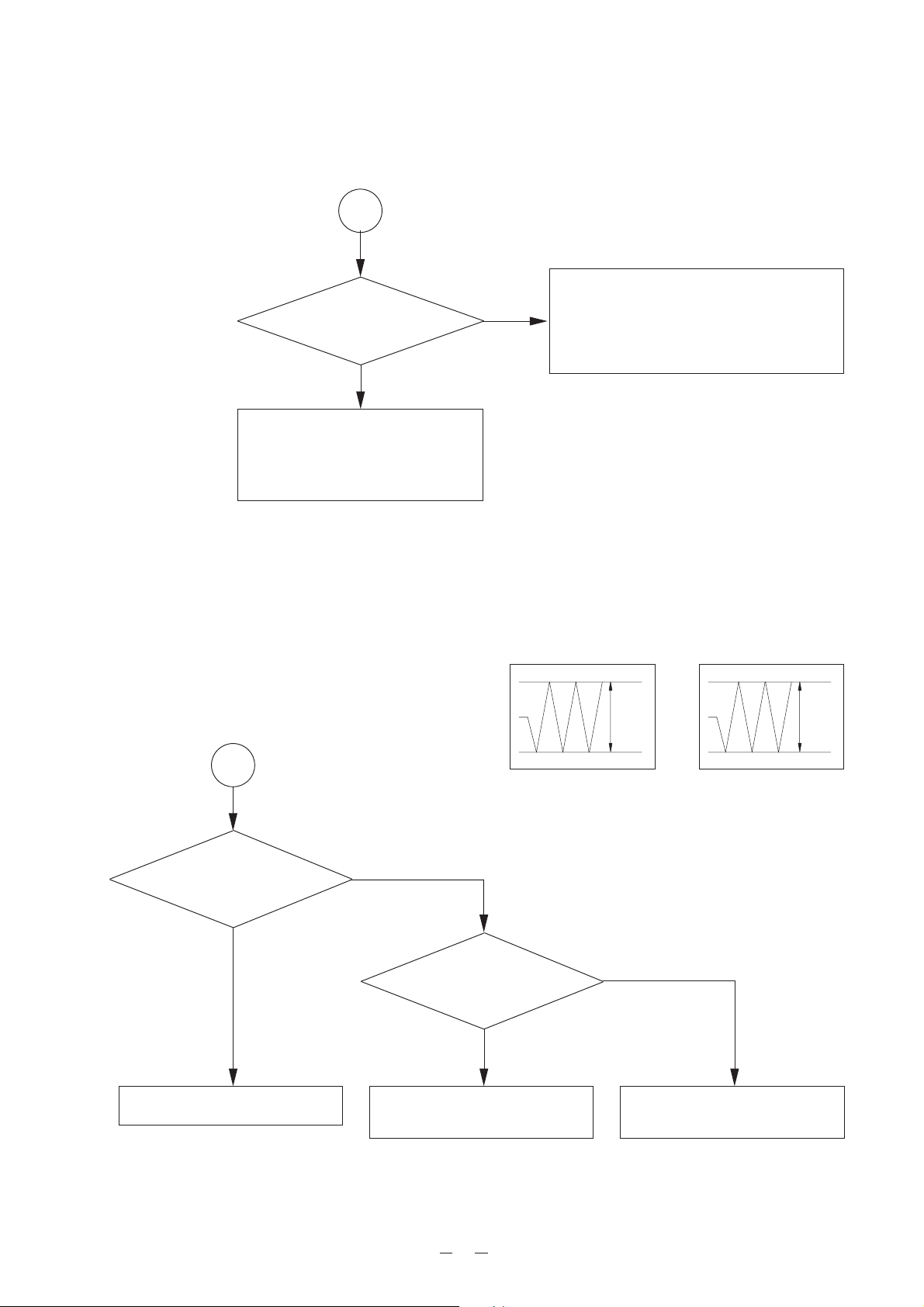
Repair Item 2-B
~1.1 V
B
Figure 7
When the waveform at IRF with an
osilloscope.
Is the waveform
at IC102 pin 35 like that
shown in fig. 7 ?
Yes
* Check IC103 pins 32, 34, 4, 5, 36,
37, 38, 57, 21 and circuit around
them.
* Check IC103 pins 8, 9 and 77.
* IC104 or IC103 is defective.
No
* Check soldering of C159 and IC103 pins
35 and 21.
* IC103 is defective.
8
Page 11

Repair Item 3: No audio signal.
3
Is IC108 pin 11 low ?
Yes
Does audio signal
appear at IC103 pins 67 (OUTR)
and 74 (OUTL) ?
No
Is IC103 pin 44 2.1 MHz
?
Yes
Is IC103 pin 40 (LRCLKI)
44.1 MHz ?
No
Yes
No
No
* Check circuit around IC108.
* IC108 is defective.
* Check circuit around IC108.
* IC108 is defective.
Yes
Does a digital
signal appear IC103 pin
42 (DATAI) ?
Yes
* Check soldering around IC103 and
IC106.
* IC103 or IC106 is defective.
No
* Check soldering around IC103 and
IC106.
* IC103 or IC106 is defective.
9
Page 12

Repair Item 4: Selected track number cannot be searched.
4
Press or key.
VC 0
Figure 8
Figure 9
Is the waveform
at TE like that shown
in fig. 8 ?
Press or key.
Is the waveform
at TE like that shown
in fig. 9 ?
* IC103 is defective.
No
No
Yes
Yes
* Pickup NG.
* Check mechanism unit and sled motor.
* Pickup unit is defective.
Repair Item 5: No audio signal output.
5
* Check soldering of IC106 and IC107.
* IC106 is defective.
* IC107 is defective.
10
Page 13

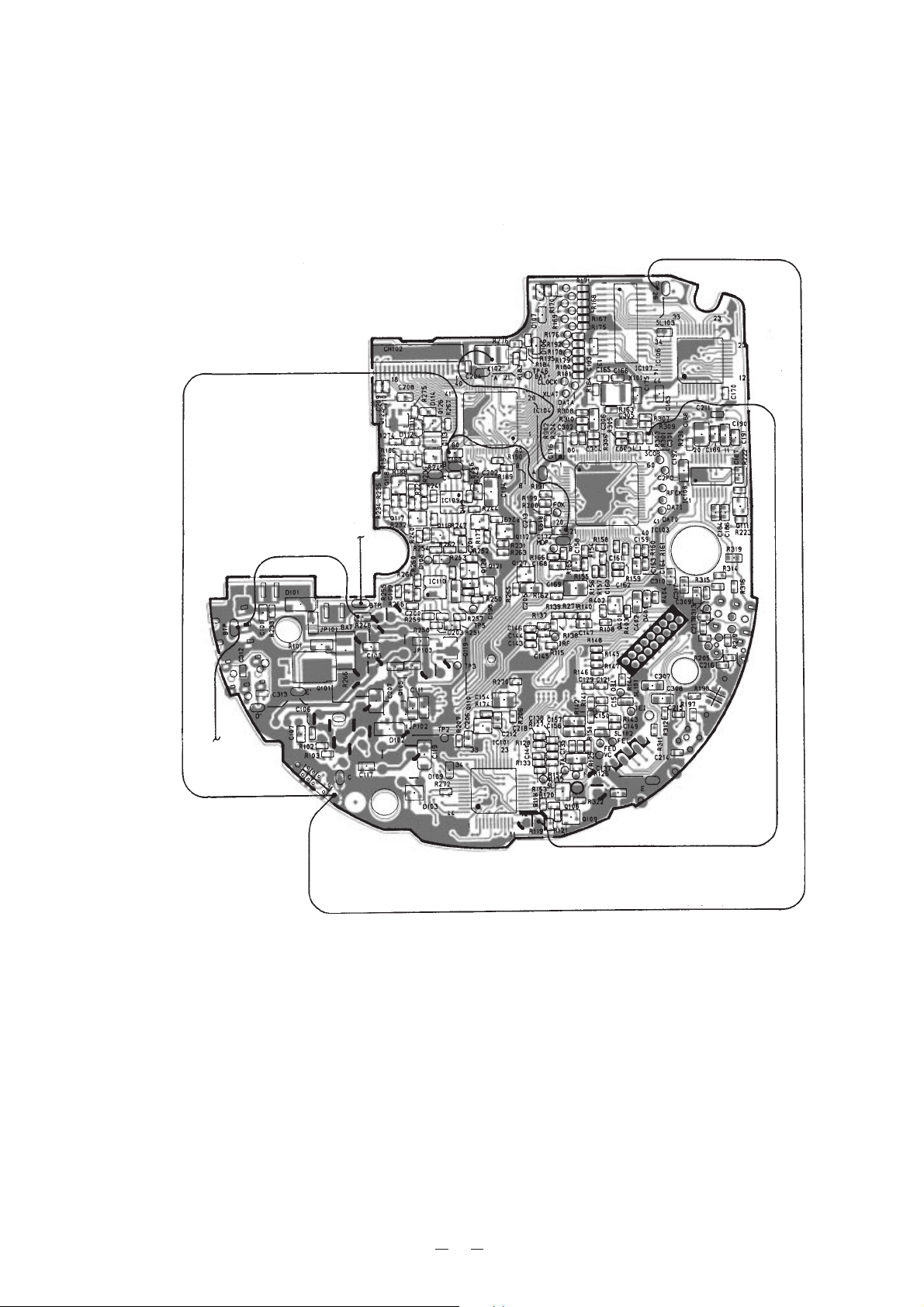
CD AMP PCB Top View
PCB VIEWS
CD Door PCB Top View
11
Page 14
CD AMP PCB Bottom View
12
Page 15

WIRING DIAGRAM
13
Page 16

IC LEAD IDENTIFICATION AND INTERNAL DIAGRAMS
IC101: BA6894K
14
Page 17

IC102: CXA1992AR
15
Page 18

IC103: CXD2589Q
16
Page 19

IC104: CXP83416-127R
17
Page 20

IC106: SM5859AF-TF
18
Page 21

IC107: KM44V1004CJ-6
19
Page 22

IC108: BA3574BFS
IC109, IC110: NJM3414AM-TE2
20
Page 23

CD Amplifier
SCHEMATIC DIAGRAMS
21
Notes:
1. All resistance values are in ohms (k=1000 ohms, M=1000 kohms).
2. All capacitance values are In lF (P=10-6 µF).
3. All resistors are 1/16 watt, unless otherwise specified.
Page 24

PIck-up CD Door
22
Page 25

PARTS LIST
PZ-7
Notes: 1. Prices and specifications are subject to change
without pointer notice.
2. As for spare parts order and supply, refer to the
“GUIDEBOOK for Spare parts Supply”, published
separately.
3. The numbers in item column correspond to the
same numbers in drawing.
23
Page 26

N Item Code No. Parts Name Specification Q'ty R Remark
Note :
N - New parts
M - Minimum order/supply quantity
R - Rank
ELECTRICAL PARTS
DIODES
D101/102 2390 1883 Diode RB160L-40TE25 2 C PZ-7 Common
D103 2390 1729 Diode RB411DT146 1 C PZ-7 Common
D106/107/108/110 7101 1194 Diode MA111-TX 4 C PZ-7 Common
D801/802/803 2310 8399 Diode RD5.6ESB2 3 C PZ-7 Common
IC's
N IC101 1915 0140 IC / BA6894K 0911-204-0-00 1 A PZ-7 Common
N IC102 1915 0141 IC / CXA1992AR 0911-203-9-00 1 A PZ-7 Common
N IC103 1915 0142 IC / CXD2589Q 0911-203-8-00 1 A PZ-7 Common
N IC104 1915 0143 IC / CXP83416-127R 0037-405-0-00 1 A PZ-7 Common
N IC106 1915 0144 IC / SM5859AF-TF 0911-842-3-00 1 A PZ-7 Common
N IC107 1915 0145 IC / KM44V1004CJ-6 0911-839-4-00 1 A PZ-7 Common
N IC108 1915 0146 IC / BA3574BFS 0911-204-1-00 1 A PZ-7 Common
N IC109/110 1915 0147 IC / NJM3414AM-TE2 0911-842-2-00 1 A PZ-7 Common
JACK
J101 3502 0003 Jack / power MOJ-D201LK 1 B PZ-7 Common
J102 1909 5601 Jack HSJ171501110 1 B PZ-7 Common
COIL
L101/104 3841 1568 Coil RCR-875D-330LM 2 C PZ-7 Common
L102 3013 1197 Coil RCH-875-100M 1 C PZ-7 Common
N L103 1915 0148 Coil / RCR-664D-102K 0990-561-0-25 1 C PZ-7 Common
L105 3841 1869 Coil 0990-869-5-05 1 C PZ-7 Common
LCD PANEL
N LC101 1915 0149 LCD 0040-420-0-0013 1 C PZ-7 Common
TRANSISTORS
Q101 2253 0709 Transistor 2SD1758TLQ 1 B PZ-7 Common
Q102/103/104 1909 9831 Transistor 2SD1302-T 3 B PZ-7 Common
Q105/119 1909 6532 Transistor 2SB1132Q 2 B PZ-7 Common
Q107/108/116/117
Q121
Q109/110/111/112
Q115/118/120/127
Q113 1909 5851 Transistor DTA114TKA 1 B PZ-7 Common
Q114 1909 5850 Transistor DTC114TKA 1 B PZ-7 Common
N SW101 1915 0150 Switch / slide 0028-434-0-0013 1 C PZ-7 Common
SW102 3412 1484 Switch / push ESE11S 1 C PZ-7 Common
SW103 3412 1498 Switch / slide SS347B22H4.4K 1 C PZ-7 Common
N SW104~109 1915 0151 Switch / TP-tach 0028-667-0-0001 6 C PZ-7 Common
VR101 2765 1764 Potentiometer 0031-639-1-03 1 C PZ-7 Common
N X101 1915 0152 Resonator / ceramic 0038-999-0-00 1 C PZ-7 Common
N X102 1915 0153 Resonator / ceramic 0038-800-0-00 1 C PZ-7 Common
2250 1288 Transistor 2SA1037K-S 5 B PZ-7 Common
2252 1211 Transistor 2SC2412K-BR 8 B PZ-7 Common
SWITCHES
VARIABLE RESISTORS
OSCILLATOR
24
Page 27

N Item Code No. Parts Name Specification Q'ty R Remark
Note :
N - New parts
M - Minimum order/supply quantity
R - Rank
MECHANICAL PARTS
N 1 1915 7002 Case / upper 2563-808-0-01 1 X PZ-7 Common
2 6924 3190 Label / FCC caution 0074-235-0-00 1 X for USA
2 6923 6070 Label / caution 0074-227-0-00 1 X for EU
N 3 1915 0162 Knob / open 2563-861-0-01 1 X PZ-7 Common
N 4 1915 0156 Lever / lock 2563-270-0-00 1 X PZ-7 Common
N 5 1915 0110 Mechanical unit / CD 2597-050-0-00 1 C PZ-7 Common
N 6 1915 0165 Amp PCB unit / CD 2563-002-0-00 1 C PZ-7 Common
N 7 1915 0166 Spring A1 / battery 2569-184-1-00 1 X PZ-7 Common
N 8 1915 0167 Spring A2 / battery 2569-185-1-00 1 X PZ-7 Common
N 9 1915 0158 Case / lower 2563-810-0-01 1 X PZ-7 Common
N 10 1915 0160 Cover / battery 2563-806-0-01 1 X PZ-7 Common
N 11 1915 0155 Label / rear 2511-850-0-83 1 X PZ-7 Common
N 12 1915 0164 Label / Identification 2540-850-0-02 1 X PZ-7 Common
N 13 1915 0163 Foot 2563-885-0-00 2 X PZ-7 Common
N 14 1915 0168 Display PCB unit 2563-005-0-00 1 X PZ-7 Common
N 14-1 1915 0174 Heat seal 2569-560-0-00 1 X PZ-7 Common
N 14-2 1915 0175 FPC 2563-550-0-91 1 X PZ-7 Common
N 15 1915 7003 Door unit / CD 2563-804-0-05 1 X for USA
N 15 1915 7004 Door unit / CD 2563-804-0-04 1 X for EU
N 16 1915 0161 Button / operation 2563-860-0-01 1 X PZ-7 Common
CD MECHANISM
N 5 1915 0110 Mechanical unit / CD 2597-050-0-00 1 C PZ-7 Common
N 5-1 1915 0171 Laser pick up 0020-015-0-0001 1 C PZ-7 Common
N 5-2 1915 0172 Motor / slide 0022-107-0-0013 1 X PZ-7 Common
N 5-3 1915 0173 Motor / CD drive 0022-093-0-00 1 X PZ-7 Common
5-4 3412 1505 Switch / micro 0036-819-0-00 1 X PZ-7 Common
5-5 6923 5210 Gear / motor 1497-255-1-00 1 X PZ-7 Common
N 5-6 1915 0174 Gear A 2597-256-0-00 1 X PZ-7 Common
N 5-7 1915 0175 Gear B 2597-257-0-00 1 X PZ-7 Common
ACCESSORY
N Z009 1915 0176 Headphone 0025-072-0-0321 1 X for USA
N Z009 1915 0177 Innerphone 0025-537-0-0113 1 X for EU
Z010 1014 9060 Adaptor / AC-DC(120/6V) 0027-194-0-0113 1 X for USA
Z010 19100178 Adaptor / AC-DC(230/6V) 0027-195-0-0113 1 X for EU
25
Page 28

Capacitors and resistors can not be supplied, because they will be available in your country.
CAPACITOR
Item Specification Q’ty
C: Chip type
C101 Ceramic, C 25V 0.1 µF +80/-20% 1
C102 Electrolytic 10V 100 µF !20% 1
C103 Ceramic, C 16V 1 µF +80/-20% 1
C105 Electrolytic 10V 100 µF !20% 1
C106 Ceramic, C 50V 33 PF !5% 1
C107 Ceramic, C 25V 0.1 µF +80/-20% 1
C108 Electrolytic 6.3V 220 µF !20% 1
C111 Ceramic, C 6.3V 47 µF !20% 1
C112 Electrolytic 6.3V 220 µF !20% 1
C115 Ceramic, C 50V 0.01 µF +80/-20% 1
C117 Ceramic, C 6.3V 10 µF !20% 1
C119 Ceramic, C 4V 47 µF !20% 1
C120 Ceramic, C 50V 1000 PF !10% 1
C121 Ceramic, C 50V 0.01 µF !10% 1
C122 Ceramic, C 25V 0.1 µF +80/-20% 1
C123 Ceramic, C 25V 0.022 µF !10% 1
C124 Ceramic, C 16V 1 µF +80/-20% 1
C125 Ceramic, C 50V 390 PF !5% 1
C126 Electrolytic 6.3V 22 µF !20% 1
C127 Ceramic, C 16V 1 µF +80/-20% 1
C129 Ceramic, C 50V 0.01 µF !10% 1
C131 Ceramic, C 50V 2200 PF !10% 1
C132 Ceramic, C 25V 0.1 µF !10% 1
C133 Ceramic, C 16V 0.033 µF !10% 1
C134 Ceramic, C 50V 0.01 µF !10% 1
C135 Ceramic, C 50V 100 PF !5% 1
C136 Ceramic, C 25V 0.056 µF !10% 1
C137 Ceramic, C 6.3V 4.7 µF !20% 1
C138 Ceramic, C 50V 0.01 µF !10% 1
C139 Ceramic, C 6.3V 22 µF !20% 1
C140 Ceramic, C 6.3V 3.3 µF !20% 1
C141 Ceramic, C 50V 0.01 µF !10% 1
C142 Ceramic, C 16V 0.033 µF !10% 1
C143 Ceramic, C 50V 0.01 µF !10% 1
C144 Ceramic, C 16V 0.033 µF !10% 1
C145 Ceramic, C 50V 0.01 µF !10% 1
C146 Ceramic, C 50V 27 PF !5% 1
C147 Ceramic, C 16V 1 µF +80/-20% 1
C148 Ceramic, C 25V 0.022 µF !10% 1
C149 Ceramic, C 50V 0.01 µF !10% 1
C150 Ceramic, C 50V 4700 PF !10% 1
C151 Ceramic, C 50V 4700 PF !10% 1
C152 Ceramic, C 25V 0.1 µF !10% 1
C153 Ceramic, C 25V 0.022 µF !10% 1
C154 Ceramic, C 6.3V 10 µF !20% 1
C156 Ceramic, C 16V 1 µF +80/-20% 1
C157 Ceramic, C 16V 1 µF +80/-20% 1
C158 Ceramic, C 25V 0.1 µF +80/-20% 1
C159 Ceramic, C 50V 4700 µF !10% 1
C160 Ceramic, C 16V 0.047 µF !10% 1
C161 Ceramic, C 50V 1500 PF !10% 1
C162 Ceramic, C 50V 0.01 µF !10% 1
C163 Ceramic, C 16V 1 µF +80/-20% 1
C164 Ceramic, C 50V 0.01 µF !10% 1
C165 Ceramic, C 50V 30 PF !5% 1
Item Specification Q’ty
C166 Ceramic, C 50V 30 PF !5% 1
C168 Ceramic, C 25V 0.1 µF +80/-20% 1
C169 Ceramic, C 6.3V 47 µF !20% 1
C170 Ceramic, C 50V 56 PF !5% 1
C172 Ceramic, C 25V 0.1 µF +80/-20% 1
C175 Ceramic, C 25V 0.1 µF +80/-20% 1
C176 Ceramic, C 16V 1 µF +80/-20% 1
C180 Ceramic, C 25V 0.1 µF +80/-20% 1
C183 Ceramic, C 25V 0.1 µF +80/-20% 1
C184 Ceramic, C 16V 1 µF +80/-20% 1
C186 Ceramic, C 16V 1 µF +80/-20% 1
C187 Ceramic, C 25V 0.1 µF +80/-20% 1
C188 Ceramic, C 6.3V 4.7 µF !20% 1
C189 Ceramic, C 16V 1 µF +80/-20% 1
C190 Ceramic, C 6.3V 10 µF !20% 1
C191 Ceramic, C 16V 1 µF +80/-20% 1
C192 Ceramic, C 6.3V 10 µF !20% 1
C193 Ceramic, C 25V 22 µF +80/-20% 1
C194 Ceramic, C 6.3V 22 µF !20% 1
C195 Electrolytic 6.3V 100 µF !20% 1
C197 Electrolytic 6.3V 220 µF !20% 1
C198 Ceramic, C 6.3V 10 µF !20% 1
C199 Ceramic, C 16V 1 µF +80/-20% 1
C200 Ceramic, C 16V 0.047 µF !10% 1
C201 Ceramic, C 16V 1 µF +80/-20% 1
C202 Ceramic, C 16V 1 µF +80/-20% 1
C203 Ceramic, C 16V 1 µF +80/-20% 1
C205 Ceramic, C 6.3V 10 µF !20% 1
C206 Ceramic, C 16V 1 µF +80/-20% 1
C207 Ceramic, C 6.3V 47 µF !20% 1
C209 Ceramic, C 50V 1000 PF !10% 1
C210 Ceramic, C 50V 1000 PF !10% 1
C212 Ceramic, C 16V 1 µF +80/-20% 1
C213 Ceramic, C 50V 150 PF !5% 1
C214 Ceramic, C 50V 1000 PF !10% 1
C216 Ceramic, C 50V 1000 PF !10% 1
C217 Ceramic, C 50V 1000 PF !10% 1
C220 Ceramic, C 50V 1000 PF !10% 1
C221 Ceramic, C 50V 1000 PF !10% 1
C301 Ceramic, C 50V 680 PF !10% 1
C302 Ceramic, C 50V 680 PF !10% 1
C303 Ceramic, C 50V 150 PF !5% 1
C304 Ceramic, C 50V 150 PF !5% 1
C305 Ceramic, C 6.3V 10 µF !20% 1
C306 Ceramic, C 6.3V 10 µF !20% 1
C307 Ceramic, C 6.3V 10 µF !20% 1
C308 Ceramic, C 6.3V 10 µF !20% 1
C309 Ceramic, C 25V 0.22 µF +80/-20% 1
C310 Ceramic, C 25V 0.22 µF +80/-20% 1
C311 Ceramic, C 16V 1 µF +80/-20% 1
C401 Ceramic, C 50V 1000 PF !10% 1
26
Page 29

RESISTOR
All resistors are chip type, 1/16watts, !5% unless
otherwise specified.
Item Specification Q’ty
R101 2.2Ω 1/8W 1
R102 10Ω 1
R103 1.5KΩ 1
R104 18Ω 1
R105 18Ω 1
R106 100Ω 1
R107 47Ω 1
R108 4.7KΩ 1
R109 150KΩ 1
R110 100KΩ 1
R112 1KΩ 1
R113 56KΩ 1
R114 33KΩ 1
R116 8.2KΩ 1
R117 33KΩ 1
R118 33KΩ 1
R119 18KΩ 1
R120 27KΩ 1
R121 10KΩ 1
R122 68KΩ 1
R123 10KΩ 1
R124 680KΩ 1
R125 270KΩ 1
R126 120KΩ 1
R127 390KΩ 1
R128 150KΩ 1
R129 150KΩ 1
R130 15KΩ 1
R132 39KΩ 1
R133 150KΩ 1
R134 0Ω 1
R135 120KΩ 1
R136 330KΩ 1
R137 2.2KΩ 1
R138 4.7KΩ 1
R139 10KΩ 1
R140 1MΩ 1
R141 100KΩ 1
R142 100KΩ 1
R143 100KΩ 1
R144 91Ω 1
R145
~ 47KΩ 4
R148
R149 100KΩ 1
R150 100KΩ 1
R151 15KΩ 1
R152 15KΩ 1
R153 15KΩ 1
R154 470KΩ 1
R155 1MΩ 1
R156 3.3KΩ 1
R157 3.3KΩ 1
R158 10KΩ 1
R159 1MΩ 1
Item Specification Q’ty
R160 470KΩ 1
R161 10KΩ 1
R162 10Ω 1
R163 100KΩ 1
R164 1KΩ 1
R165 10KΩ 1
R166 2.2KΩ 1
R167
~ 47KΩ 7
R173
R174 4.7KΩ 1
R175 47KΩ 1
R176 47KΩ 1
R177 10KΩ 1
R178
~ 47KΩ 6
R184
R185 5.6KΩ 1
R186 10KΩ 1
R187 10KΩ 1
R188 10KΩ 1
R189
~ 47KΩ 5
R193
R195 4.7KΩ 1
R196 47KΩ 1
R197 47KΩ 1
R198 47KΩ 1
R200 1KΩ 1
R201 1.5KΩ 1
R202 2.2KΩ 1
R203 4.7KΩ 1
R204 12KΩ 1
R206 100KΩ 1
R207 33KΩ 1
R220 27KΩ 1
R221 11KΩ 1
R222 100KΩ 1
R223 10KΩ 1
R231 4.7KΩ 1
R232
~ 10KΩ 10
R240
R241 1KΩ 1
R242 1KΩ 1
R243 10KΩ 1
R244 100Ω 1
R245 10KΩ 1
R246 10KΩ 1
R247 10KΩ 1
R248 22Ω 1/10W 1
R249 2.2KΩ 1
R250 220Ω 1
R251 6.8KΩ 1
R252 2.7KΩ 1
27
Page 30

Item Specification Q’ty
R253 120KΩ 1
R254 100KΩ 1
R255 1KΩ 1
R256 1KΩ 1
R157 10KΩ 1
R258 15KΩ 1
R259 20KΩ 1
R260 10KΩ 1
R261 10KΩ 1
R262 1KΩ 1
R263 10KΩ 1
R264 4.7K Ω 1
R265 2.2K Ω 1
R266 5.6Ω 1W Metal Type 1
R268 10KΩ 1
R269 0Ω 1
R270 10KΩ 1
R272 10KΩ 1
R276 0Ω 1
R301
~ 12KΩ 6
R306
R307 1KΩ 1
R308 1KΩ 1
R309 100KΩ 1
R310 100KΩ 1
R311 15KΩ 1
R312 15KΩ 1
R313 2.2K Ω 1
R314 2.2K Ω 1
R315 1KΩ EMI BEAD 1
R316 1KΩ EMI BEAD 1
R322 0Ω 1
R401 1KΩ 1
R405 100KΩ 1
JP101 0Ω 1/8W 1
JP102 0Ω 1/8W 1
JP103 0Ω 1/10W 1
JP277 0Ω 1/10W 1
JP278 0Ω 1/10W 1
JP319 0Ω 1/10W 1
28
Page 31

EXPLODED VIEWS
Cabnet
15
16
2
1
4
3
5
14-1
14
6
14-2
8
7
9
13
13
10
11
12
29
Page 32

CD Mechanism
5-4
5-2
5-5
5-6
5-1
5-7
5-3
30
Page 33

AF1200071A
CASIO TECHNO CO.,LTD.
Service Division
8-11-10, Nishi-Shinjuku
Shinjuku-ku, Tokyo 160, Japan
Telephone: 03-3347-4926
 Loading...