

Page 1
(with price)
INDEX
FV-600BA/BB(KX-0761BIA/BIB)
FV-600BM (KX-0761BMA)
JUL. 1995
R
Page 2

CONTENTS
SPECIFICATIONS ......................................................................................... 2
SAFETY MEASURES.................................................................................... 3
ALARM DESCRIPTION................................................................................. 3
BLOCK DIAGRAM ........................................................................................ 4
OPTICAL DIAGRAM ..................................................................................... 5
MONITOR SWITCHES .................................................................................. 5
TROUBLESHOOTING................................................................................... 6
PARTS LIST FOR MAIN BLOCK.................................................................. 7
FOCUS ADJUSTMENT ................................................................................. 8
ADJUSTMENT MODE ................................................................................... 9
DISASSEMBLY ........................................................................................... 10
REPLACING THE FUSE ............................................................................. 18
REPLACING THE LAMP............................................................................. 19
PRINTED CIRCUIT BOARDS ..................................................................... 21
EXPLODED VIEWS ..................................................................................... 26
ELECTRICAL PARTS LIST......................................................................... 29
MECHANICAL PARTS LIST ....................................................................... 48
CPU PIN FUNCTION ................................................................................... 51
SCHEMATIC DIAGRAMS ........................................................................... 55
WAVEFORMS.............................................................................................. 60
— 1 —
Page 3
SPECIFICATIONS
Item Specification
Receiving channels (BA and BB) VHF: 2 to 12 UHF: 13 to 69
Power supply BM (For U.S.A. and Canada): 110-130 V
BA: 100–120 V BB: 220–240 V
Power consumption BM (For U.S.A. and Canada): 118 W
BA: 116 W BB: 119 W
Color system NTSC
Input/Output terminals
External antena: F connector
Video in: 1.0 Vp-p, 75 Ω
Audio in: 308 m Vrms, 47 kΩ minimum
Earphone: 3.5 mm mini jack, 16 Ω
Screen size (Built-in screen) 10 inches
LCD panel
Size: 2.4 inches
Type: Transparent TN liquid crystal panel
Driver: a-Si TFT active matrix
No. of picture element: 245,960 (440 X 559) dots
Lens Wide angle lens (F4.8, f=39.76 mm)
Lamp 80 W metal halide
Lamp life Approx. 2,000 hours
Focus adjustment range 20 inches to 100 inches (Image size)
Speaker output 3 W
Operating temperature 32° to 104°F (0° to 40°C)
Dimensions 11-5/16 (W) X 5-5/8 (D) X 16-1/8 (H) inches
28.8 (W) X 14.3 (D) X 41.0 (H) cm
Weight 13.3 lbs. (6.2 kg)
— 2 —
Page 4
SAFETY MEASURES
The power will be turned off automatically when FV-600 is in the following conditions.
1. Fan is stopped.
2. High temperature
(1) Thermistor detects high temperature.
(2) Bimetal detects high temperature.
3. Fan filter is not set properly.
4. Rear cover is not set properly.
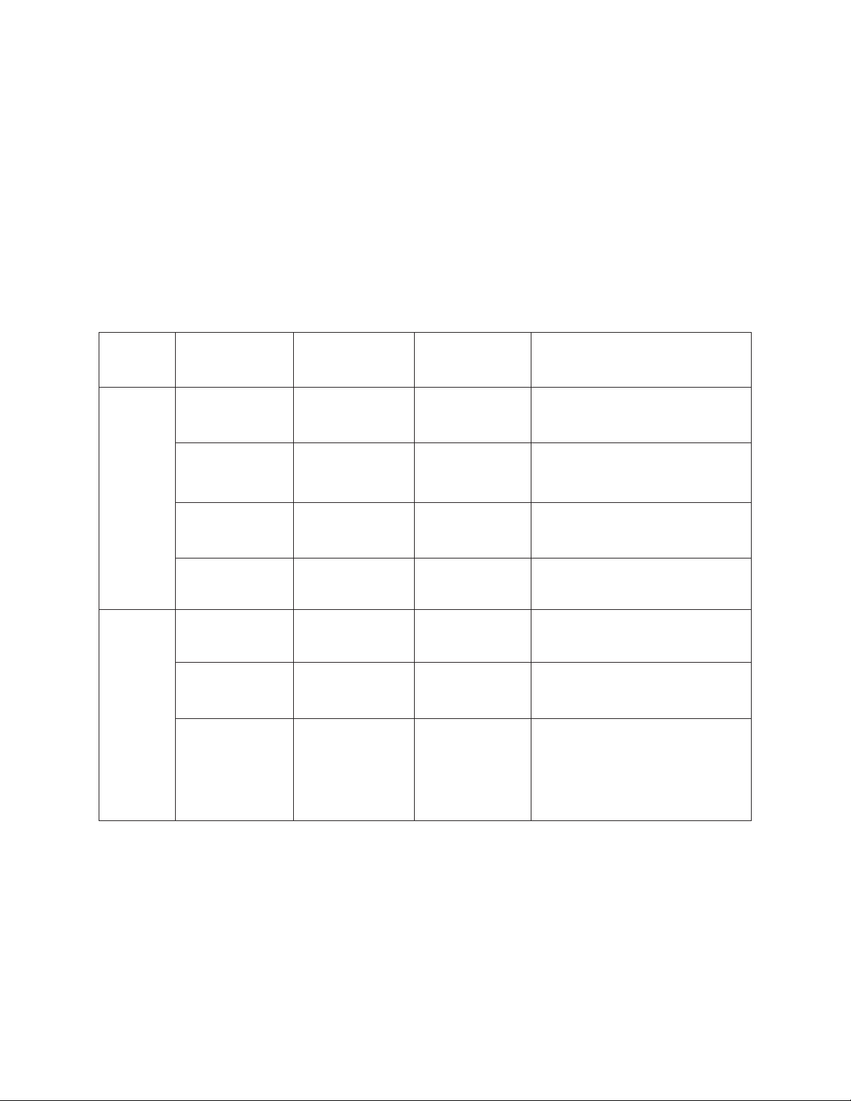
ALARM DESCRIPTION
Power LED Alarm LED Beep Description
Green On Off – Power on
OK Off Off – Power off
Red On Off – Power off by remote control
Green Blink Off – Cooling off (Fan is working.)
Green On Red Blink Twice
NG Red Blink Red Blink Three times
Red On Red Blink Once
High temperature warning
(Check the fan and fan filter.)
1. Lamp is defective.
2. Fan is defective.
1. Fan filter warning
(Check if the fun filter is set.)
2. Rear cover warning
(Check if the rear cover is set.)
— 3 —
Page 5
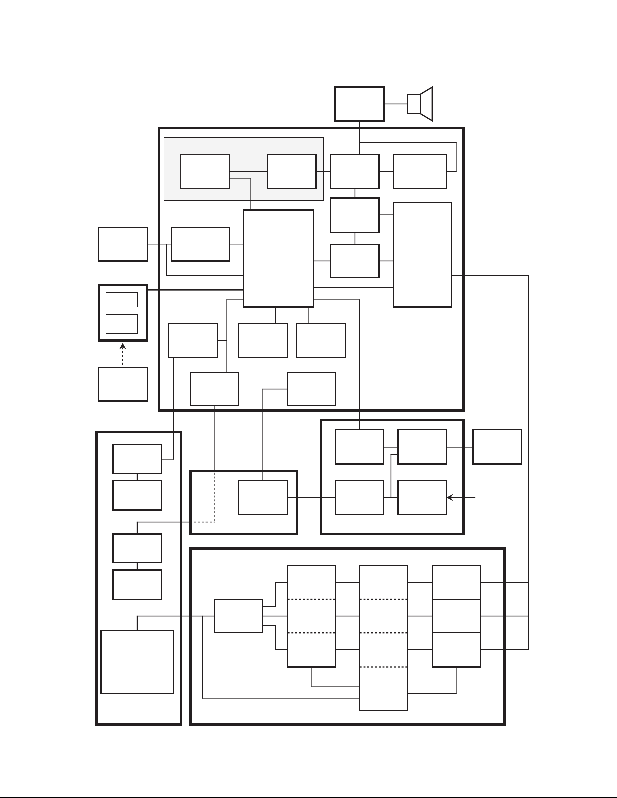
BLOCK DIAGRAM
Thermistor
RM PCB
LED
Photo
Sensor
Remote
Controller
J–PCB
Except for BM (For U.S.A. and Canada)
*
TEKN7
Tuner
Temperature
Detector
Focus
Drive
Circuit
Fan
Control
Circuit
M51496
IF
µPD17068
CPU
Key
EEP-ROM
Power
Supply
Circuit
I / O
Circuit
BA7612
SW
MCF0263
Comb
Filter
Low
Pass
Filter
Speaker
TDA7056A
Audio
Amplifier
M51406
Chrominance
Circuit
RGB
Linear PCB
Focus
Motor
Lens
Fan
Motor
Fan
440 X 559 dots
TFT LCD Module
OPM Unit
IR3Y07
Polarity
Reverser
Relay
MB4097
D/A (R)
D/A (G)
D/A (B)
Control
Circuit
12 V
Power
Supply
Power Supply PCBF–PCB
HG51B201
Line
Memory
(R)
Line
Memory
(G)
Line
Memory
(B)
Controller
Lamp
Drive
Circuit
Input
Circuit
Metal
Halide
Lamp
AC In
µPC659
A/D (R)
µPC659
A/D (G)
µPC659
A/D (B)
A/D PCB
— 4 —
Page 6
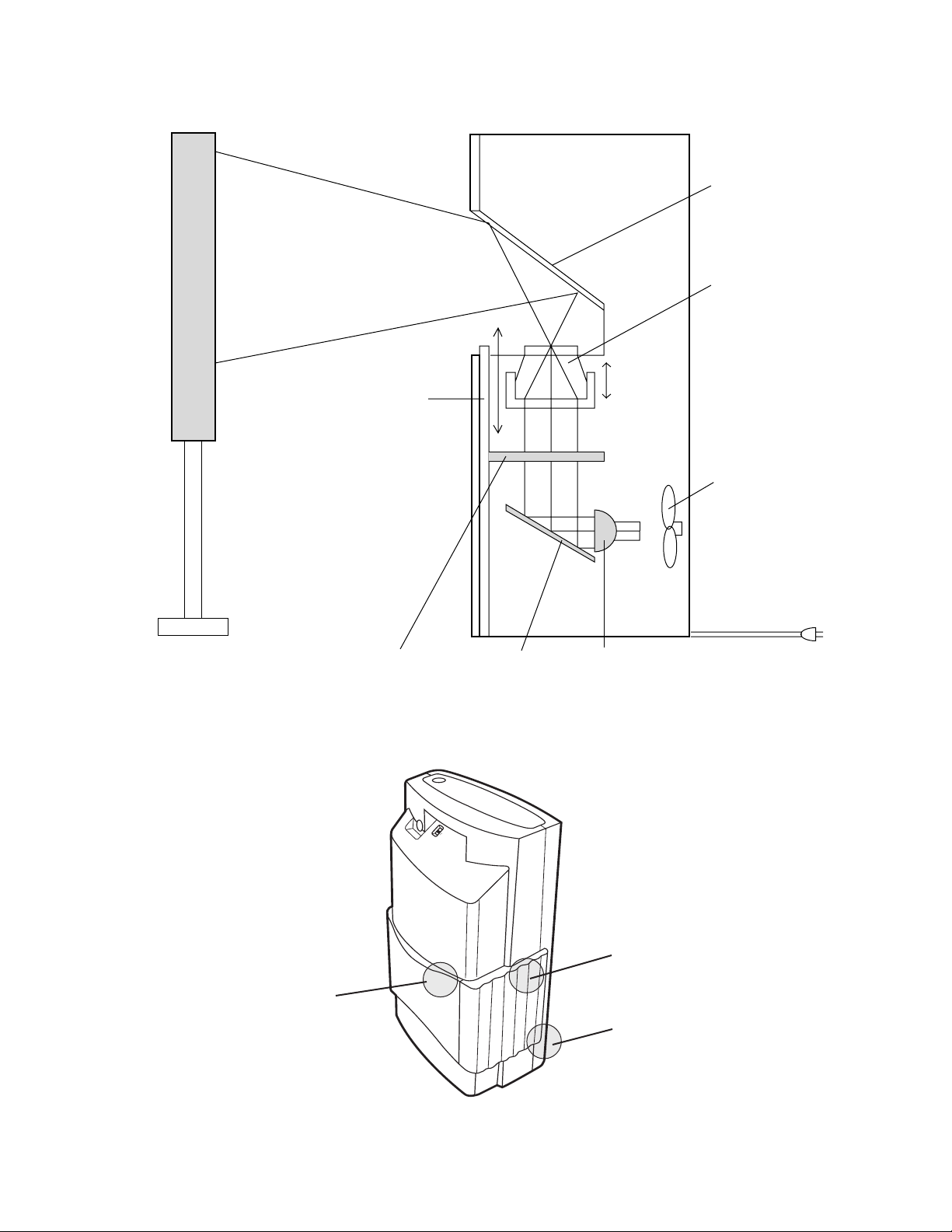
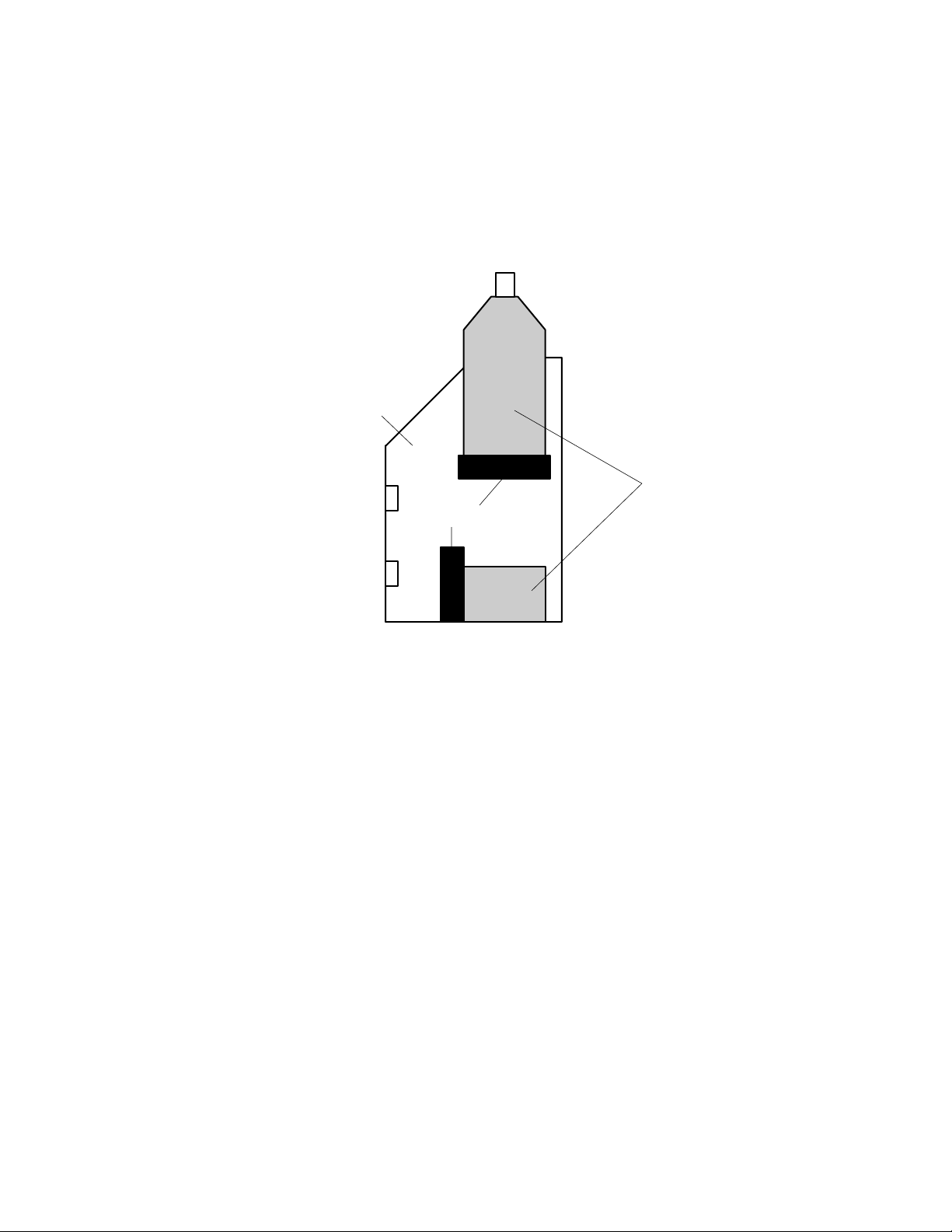
OPTICAL DIAGRAM
10 inches built-in screen
Mirror
Lens
Fan
20~100 inches screen
Rear cover monitor switch
Mirror
MONITOR SWITCHES
AC IN
LampTFT LCD module
Fan monitor switch
Built-in screen monitor switch
— 5 —
Page 7
TROUBLESHOOTING
Symptom Cause Solution
No picture Lamp is defective. Replace.
LCD is defective. Replace OPM unit.
No power supply Fuse on power supply PCB is defective. Replace.
Power supply PCB unit is defective. Replace.
Front case assembling is not correct. Assemble it correctly.
Rear cover warning Rear cover is coming off. Attach it correctly.
Rear cover monitor switch is defective. Replace.
Fan filter warning Fan filter is coming off. Attach it correctly.
Fan filter monitor switch is defective. Replace.
No change to big screen mode Built-in screen is not locked when it pressed
down.
Built-in screen monitor switch is defective. Replace.
Replace latch.
OPM UNIT TROUBLE
The precise adjustment of the optical axis is required when the OPM unit is re-assembled, and it can be
adjusted in our factory only.
Therefore replace the OPM unit when the following parts are defective.
• LCD unit
• Lens unit
• Step motor
• Fan
• Mirror
• Inner case
POWER SUPPLY TROUBLE
The individual parts for the power supply PCB unit are not supplied due to safety regulations. Replace the
power supply PCB unit when it is defective.
— 6 —
Page 8
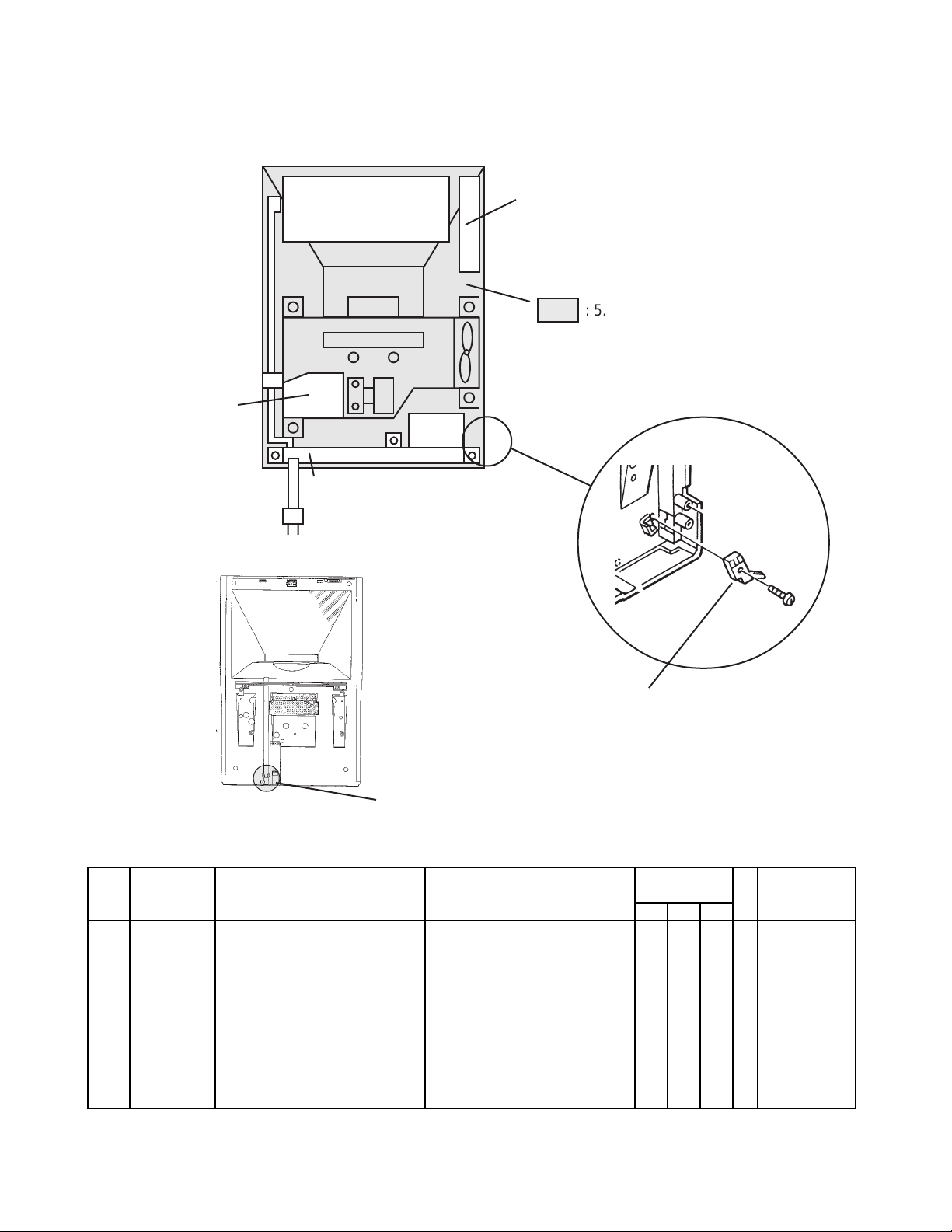
PARTS LIST FOR MAIN BLOCK
4. Lamp unit
1. Linear PCB ass'y
3. Power supply PCB unit
Rear View
2. AD PCB ass'y
: 5. OPM unit
Consists of the LCD unit, Fan, Lens
unit, and Inner case.
6. Switch
7. Latch
Front View
FOB Japan
Item Code No. Parts Name Specification Quantity M N.R.Yen
BM BA BB Unit Price
1 6610 0300 Linear PCB ass'y K140110*1 1 0 0 1 9,830
1 6610 3732 Linear PCB ass'y K140166*1 0 1 1 1 9,830
2 6610 0720 AD PCB ass'y K240263*1 1 0 0 1 5,450
2 6610 3735 AD PCB ass'y K240304*1 0 1 1 1 5,450
3 3012 1260 Power supply PCB unit SPJ1236 1 0 0 1 8,750
3 3012 1393 Power supply PCB unit SPJ1256 0 1 0 1 8,750
3 1014 8087 Power supply PCB unit SPE1257 0 0 1 1 8,750
4 1014 7954 Lamp unit MH-SA08-CA1US 1 1 1 1 3,370
5 6610 1687 OPM unit K140094*2 1 1 1 1 25,570
6 3412 1302 Switch JPS1220-0201 2 2 2 5 65
7 5860 8876 Latch 29KO 2 2 2 5 52
Notes: M – Minimum order/supply quantity
— 7 —
Page 9
FOCUS ADJUSTMENT
Focus adjustment in the 10 inches screen (built-in screen) mode is required in the following conditions.
1. The focusing gear is moved compulsorily.
2. The lens position is moved compulsorily.
3. After replacing the linear PCB ass'y.
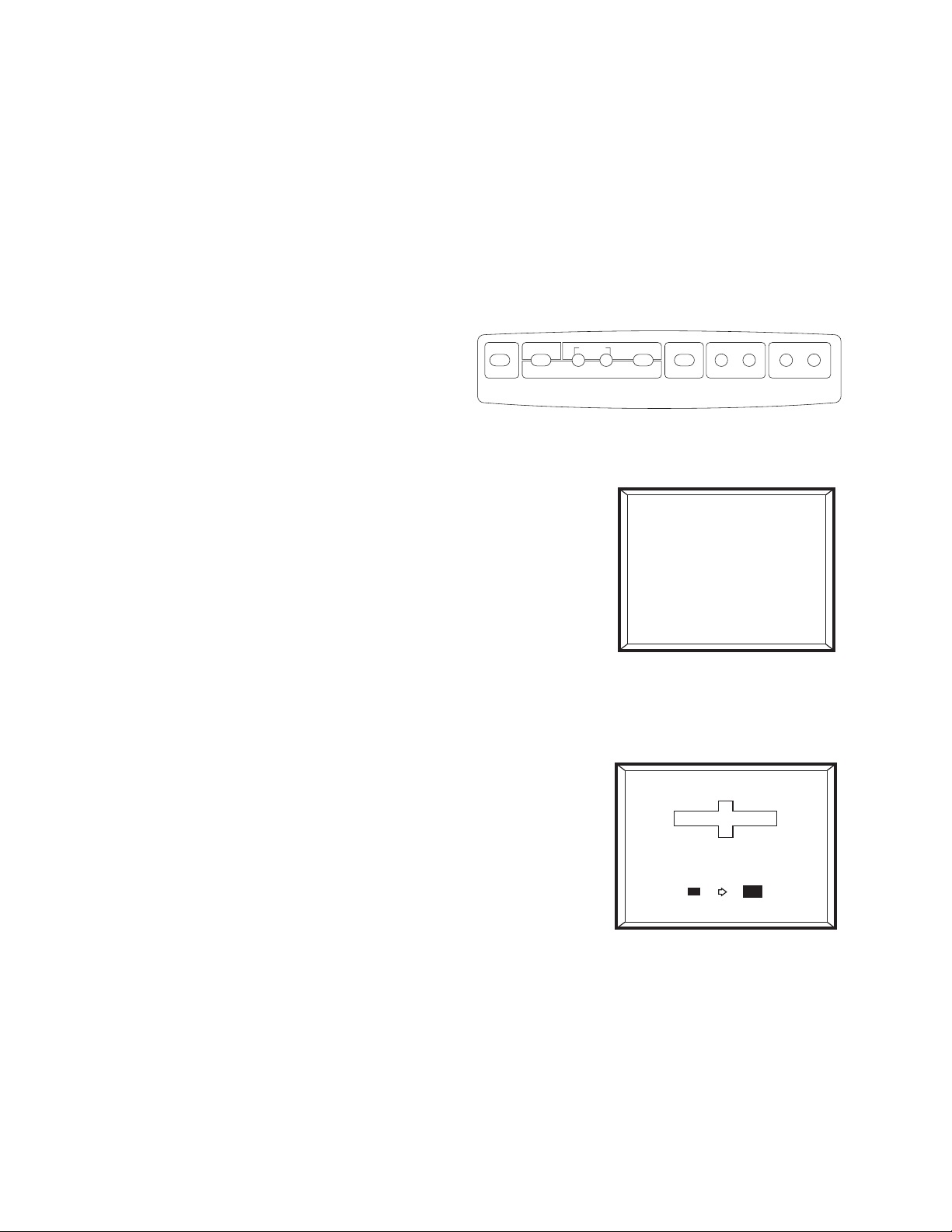
To adjust the focus in the 10 inches screen mode.
FRONT PRJ
REAR PRJ
MENU
FOCUS
[{ [{ [{
CONTROL
1. Press the MENU button for about five seconds in TV or VIDEO mode.
2. It shows the focus adjustment display and clatters for a while.
TV/VIDEO
SET
VOLUME
CHANNEL
10
FOCUS
3. Press the FOCUS +/- buttons to adjust the focus.
4. Press the SET button to set the focus.
Note:
To adjust the focus in a big screen mode (the built-in screen is lowered completely), press the FOCUS +/and SET buttons. (Refer to the owner's manual.)
— 8 —
Page 10
ADJUSTMENT MODE
In the adjustment mode, the CPU of FV-600 ignores the monitor signals. So you can turn the power on when
the cases, covers, and air filter are removed.
WARNING:
1. There are some high voltage point on the power supply PCB unit. Never touch it when the power is on.
2. To avoid eye damage, never view the light produced by the lamp directly.
TO ENTER THE ADJUSTMENT MODE:
FV-600BA/BB (Except for U.S.A. and Canada)
1. While pressing the SET button, put in the AC plug.
2. Press the power button.
To escape the adjustment mode, pull out the AC plug.
FV-600BM (For U.S.A. and Canada)
1. Remove the rear case. (Refer to Disassembly)
2. Put in the AC plug.
3. Press the button on the linear PCB indicated as the following figure.
4. Press the power button.
To escape the adjustment mode, press the SET button.
Linear PCB on FV-600BM (Top View)
— 9 —
Button A
Page 11
DISASSEMBLY
Be sure to pull out the AC plug before disassembling the unit.
(Never pull out it while the fan is working.)
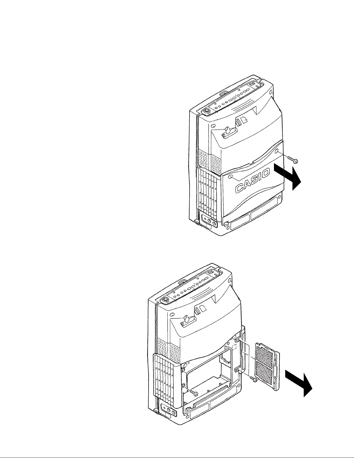
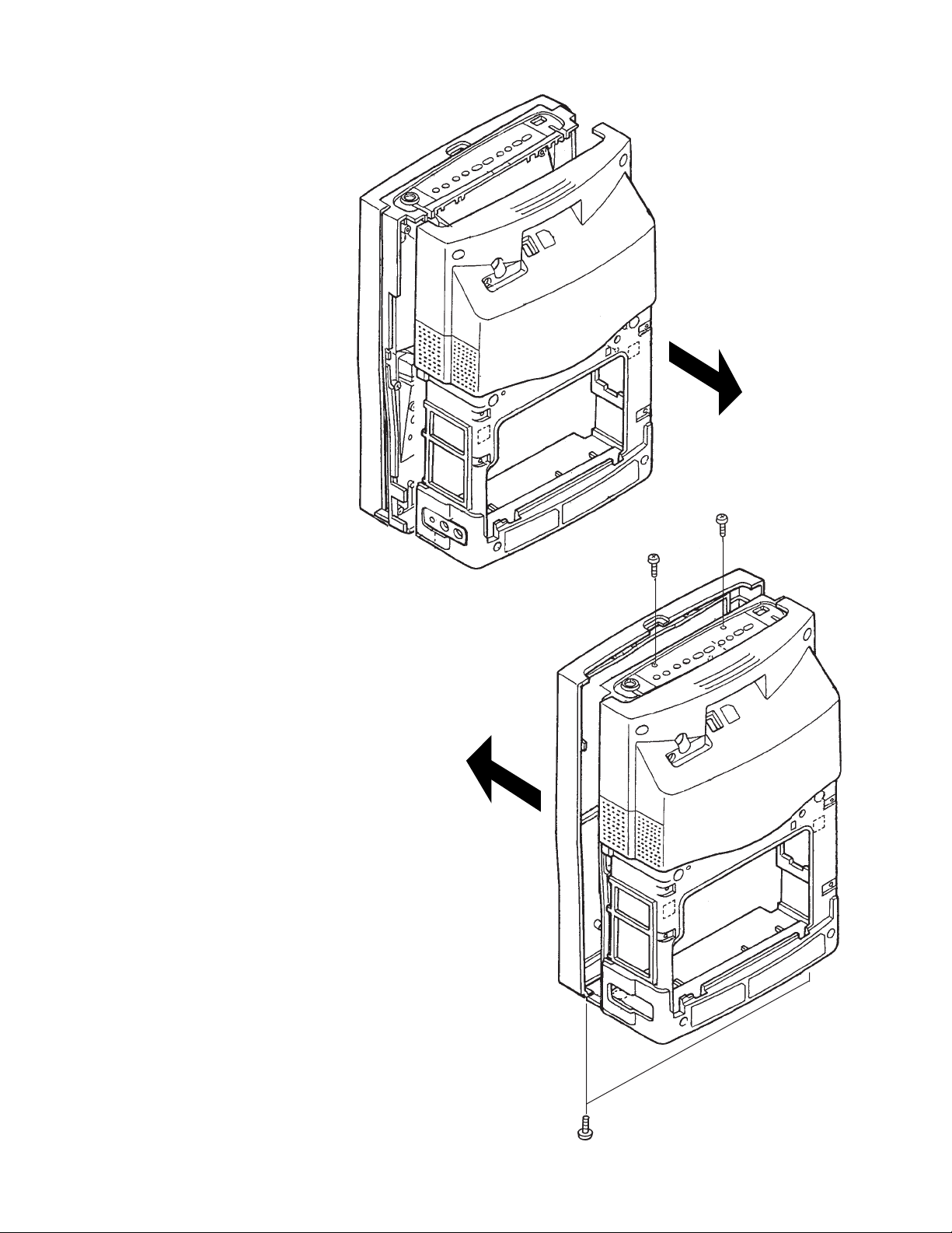
TO REMOVE THE LOUVER L AND R SUB ASS'YS:
1. Remove the two screws and the rear cover ass'y.
2. Remove the filter and the four screws that
hold the louver L and R sub ass'ys.
— 10 —
Page 12
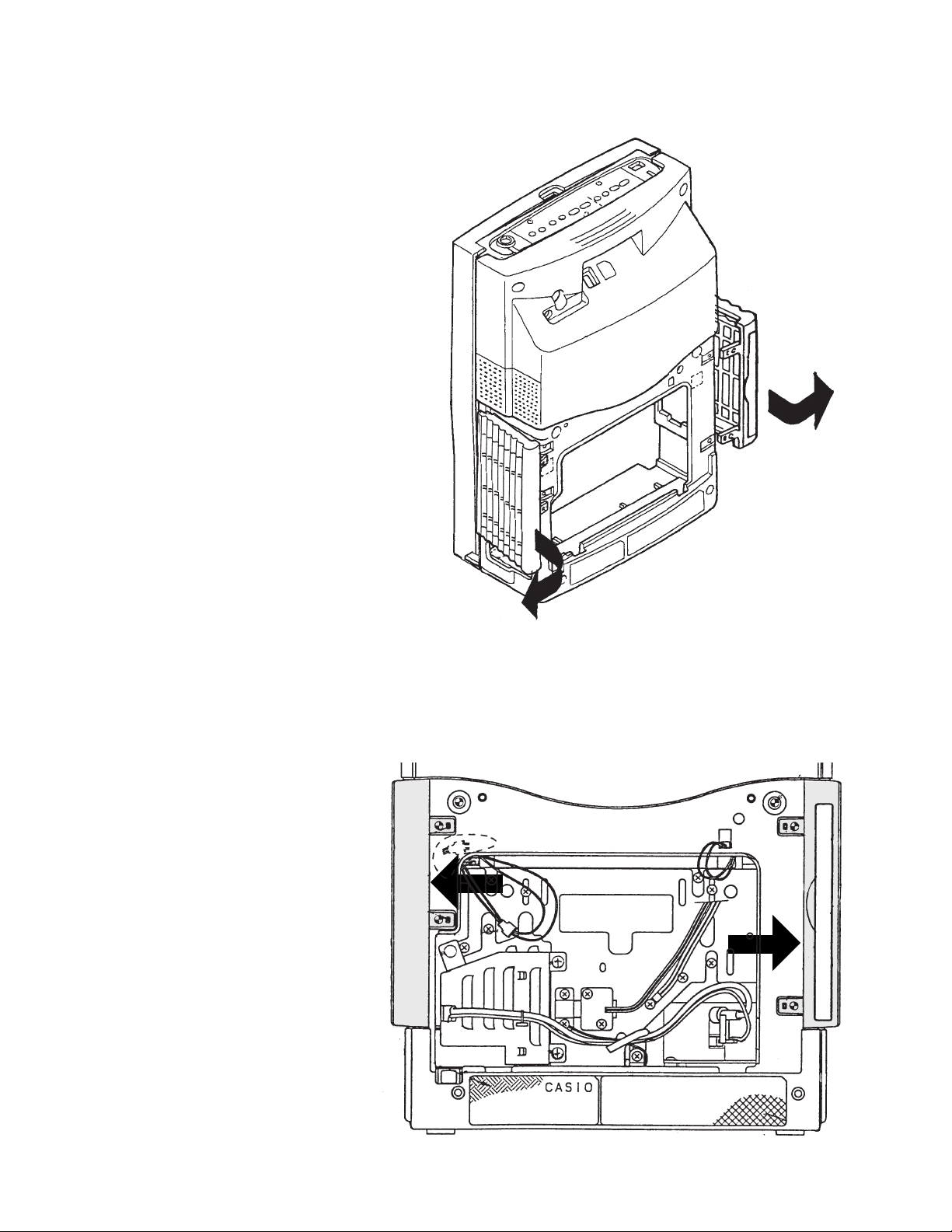
3. Remove the louver L and R sub ass'ys.
Note: To remove them, lift a part indicated by the arrows.
— 11 —
Page 13
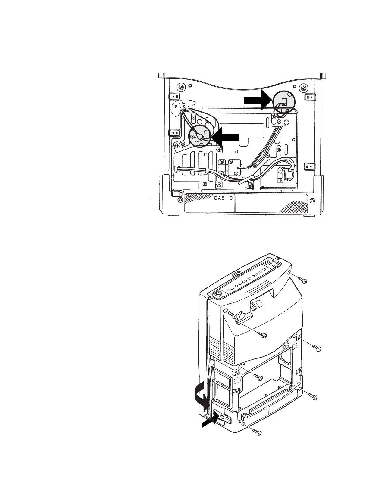
TO REMOVE THE REAR CASE SUB ASS'Y:
1. Disconnect the two wires shown in the circles.
2. Remove the seven screws and unhook the latch at the jack cover.
— 12 —
Page 14
3. Remove the rear case sub ass'y.
TO REMOVE THE FRONT CASE SUB ASS'Y:
Remove the four screws and the front case sub ass'y.
— 13 —
Page 15
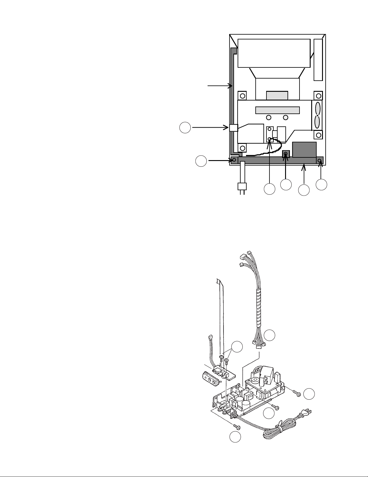
TO REMOVE THE POWER SUPPLY UNIT:
1. Remove the tape that holds the flat cable.
2. Remove the three screws.
3. Pull out the power supply unit.
4. Remove the wire of the power supply unit.
5. Remove the lamp unit.
Flat cable
1
2
6. Disconnect the cable sub ass'y.
7. Remove the two screws and the jack unit.
Flat cable
4
Rear View
Cable sub ass'y
6
7
22
3
Jack unit
— 14 —
Power supply unit
2
2
2
Page 16
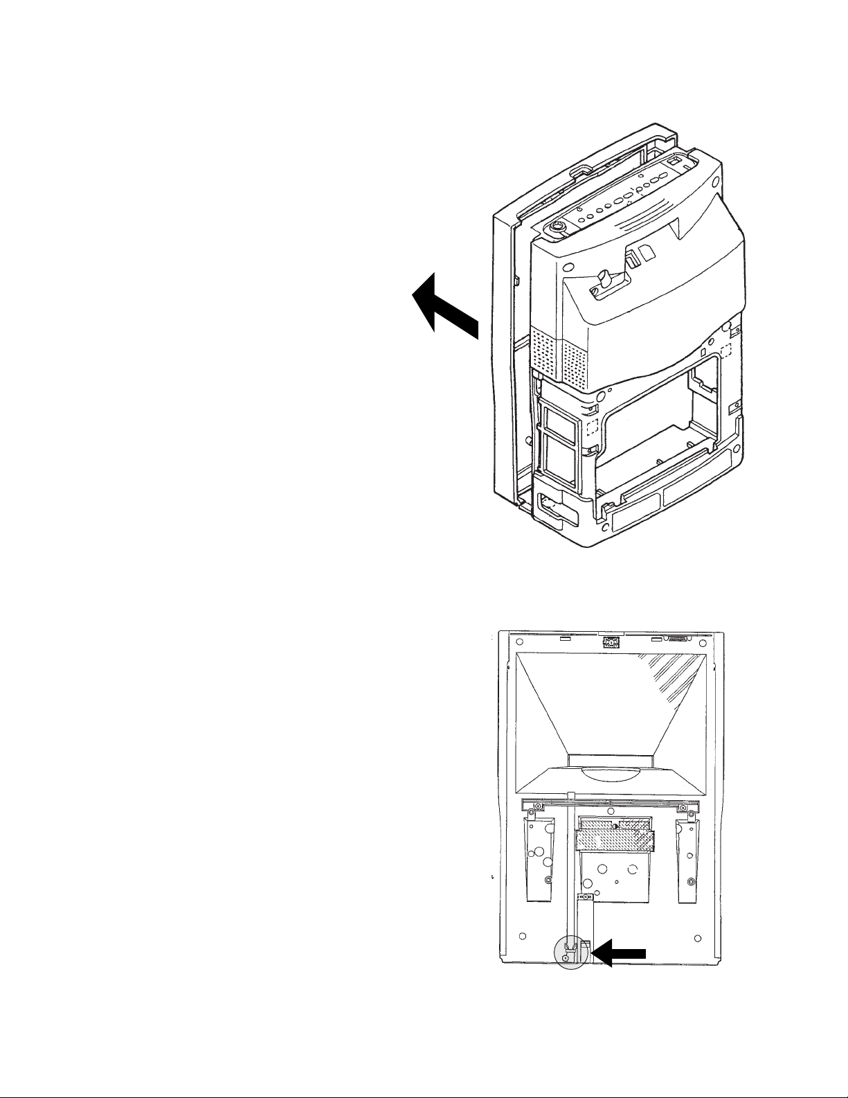
TO REPLACE THE LATCH FOR THE SCREEN:
1. Remove the front case sub ass'y.
2. Replace the latch shown in the circle.
Front View
— 15 —
Page 17
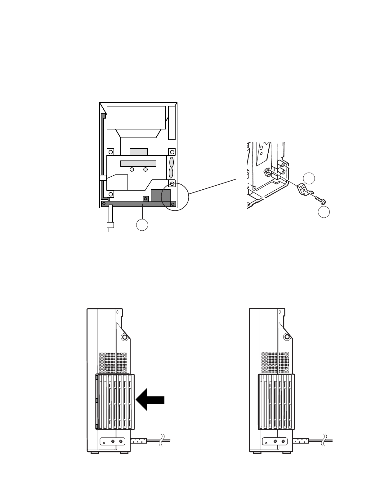
TO REPLACE THE BUILT-IN SCREEN MONITOR SWITCH:
1. Remove the power supply unit.
2. Remove the screw.
3. Disconnect the wiring.
4. Replace the switch.
4
2
1
Rear View
TO ATTACH THE LOUVER L AND R SUB ASS'YS TO THE UNIT:
Push the louver as the following figure.
— 16 —
Page 18
RE-ASSEMBLING THE AD PCB ASS'Y
WARNING:
Never use the older shield tapes when attaching them to the shield case. Use new shield tapes to insulate
the shield case and the shield tape.
Shield case
Shield tape
Adhesive tape
AD PCB unit
— 17 —
Page 19
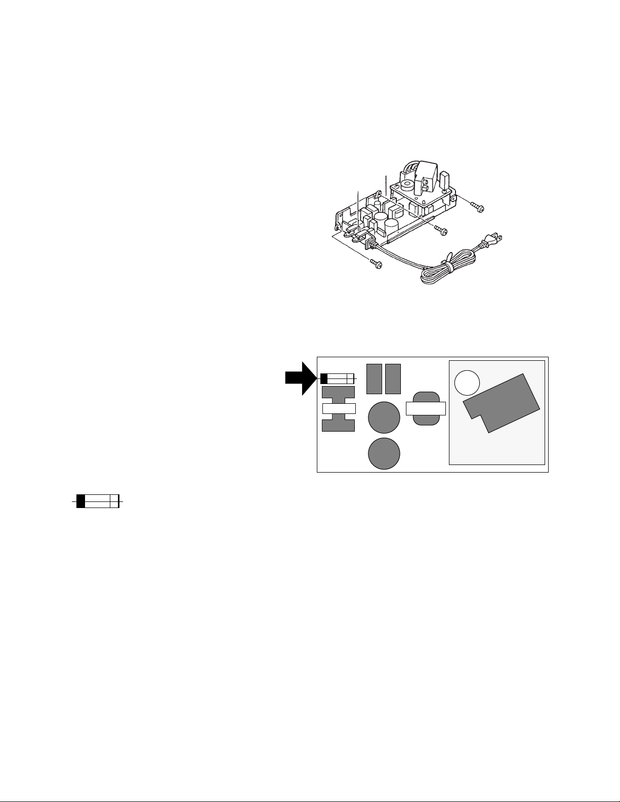
REPLACING THE FUSE
TO REPLACE THE FUSE ON THE POWER SUPPLY PCB:
1. Remove the power supply PCB unit .
(Refer to Disassembly.)
2. Replace the fuse.
CAUTION:
This symbol indicates the F1 fuse on the power supply PCB.
Replace with the same type 5A, 125V fuse.
ATTENTION:
Ce symbole indique le F1 fusible se trouvant sur la carte de circuit electrique.
Ne remplacer ce fusible que par un fusible identique de 5A, 125V.
— 18 —
Page 20

REPLACING THE LAMP
WARNING:
1. To avoid the electric shock, be sure to pull out the AC plug before removing the rear cover. The lamp
voltage is 21 kV at start up.
2. Be sure to leave the FV-600 unit at least 30 minutes after pulling out the AC plug, because the lamp unit
is in the high temperature and high pressure while it is working.
There is a risk of explosion when you bump the electrode of the lamp in the high pressure condition.
3. Be careful not to bump the point of the electrode (made by glass) into the chassis.
4. Be careful not to touch the electrode or reflector of the new lamp unit.
5. After replacing the lamp unit, keep the power on while at least 5 minutes once.
Electrode
Refrector
The precise adjustment of the optical axis is required when the lamp unit is assembled, therefore the individual parts are not supplied .
The lamp life is approximately 2,000 hours.
TO REPLACE THE LAMP:
1. Turn the power off.
2. Pull out the AC plug after the fan is stopped. (About 30 seconds)
(Never pull out it while the fan is working.)
3. Remove the rear cover.
— 19 —
3
Page 21

4. Disconnect the cable.
5. Remove the three screws.
6. Remove the lamp.
(Be careful not to bump the point of the electrode into the chassis.)
Lamp
5
5
4
5
7. Remove the two screws and the plate.
Electrode
— 20 —
Page 22

Linear
FV-600BA/BB
PRINTED CIRCUIT BOARDS
CP902
CN513
CP904
R903
1
6
CP903
Q902
R902R904
R901
C331
IC302
CP300
CP211
C237
R220
R905
C993
1
CP105
C211
C246
R228
C245
CN509
2 1
CP200
C247
D203
CP122
CP102
CP103
CP104
R553
C539
CP154
R301
R302
C332
R202
R205
+
R555
CP106
C244
C216
CP165
1
L201
C202
C220
S509
CHUP
Q303
R308
CP204
CP205
C224
R309
C223
C143
R108
C333
CP202
CP203
C222
C221
Q103
CP523
L301
C334
C218
CP164
Q104
S508
CHDN
CP107
C219
R110
C147
R116
C340
C319
R349
C359
R352
R303
CP108
R109
R372
R373
R111
+
R353
Q302
CP522
CP521
R338
R337
C350
C349
IC301
R355 R356 C361
C358
C360
R307
Q301
R306
CP109
CP207
CP110
R206
R207C226
CP206
Q201
C227
R211
R210
S507
C347
R334
R336
C318
C348
+
R305
R304
D204Q203
R229
C225
L202
R209
+VOL–
+
C317
R333
C345
R332
1
SW201
C239
R219
C238
C236
R208
C228
CP163
CP112
ROD
EXT
CP210
CP212
CP209
S506
CN516
CP162
S201
R227C240C241
C235
C229
4
1
D109
Q202
R226
R222
C242
R212 C232
L203
CP111
CP303
CP302
CP301
R224
R216
R217
CP516
CP520
C243R223
C231
C203
R218
CP208
C336
R330R329R328
C234
C230
INPUT
R315
L302
C341
L303
C342
L304
C343
R114
CP213
R215
R214
+
R314
C337
Q304
R360R361R362
Q305
Q306
R115
CP174
C131
C132
S502
R318
R317
C338
C355
CP534
R321
CP532
R354
R544
CP538
R320
C339
1
CN515
14
C940
R916
C939
R324
R311
R915
R914
R323
CP533
R312
CP535
CP538
CP160
CP116
R907
R910
R908
R909
S505
ENTER
CP113
C335
CP537
R911
C935
Q901
R922
R118
CP159
CP158
CP157
C936
4
IC902
C942
CP519
CP114
R119
L104
R921
CP518
D108
CP161
CP115
CP900
R913
R919
R920
C938
R923
R571 R572
C142
C140
C141
C941
S501
CP155
D104
CP901
CP156
CN510
1 2
D106
D105
D103
D102
CP117
CP525
+ADJ–
S510
IC501
C531
C532
R554
CN507
1
CP503 CP505
C138
CP169
CP125
R549
R537
CP506CP504CP502
CP524
1
R104
C136
R536
C544
C543
CP166
C137
IC101
R117
CP527
CP526
CP532
S5
04
SEL
R576
8
CP118
1
CP120
1
IC504
CP531
R533
R575
R102
R101
CP530
IC502
R534
R574
R573
CP130
CP517
R558
R559
CP124
CP511
CP510
R525R521
C538
CP119
6
1
R561
R564
IC506
R522
R523R526 C536
IC503
CP529
D506D507
D510D511
CN514
S503
REV
CP513
CP512
C551
CP173
5
CP153
CP151
Q503
D503
R508
CP134
R563
1
C134
C133
CP172
CP167
CP131
CP501
CP507
R527
CP509
CP508
CP132
CP170
CP121
C145
CP126
C146
1
CP500
CN506
CN502
CP152
CP171
R552
R551
CP168
2
CN504
3 1
CN512
1
CN511
2
CN501
1
6
1
2
1
2
1
2
1
CN508
Top View
— 21 —
Page 23

R515
C540
R512
R513
R520
C541
R514
R511
R516 R517
R518
R519
R906
C932
C302
R506
R557
R509 R505
R569
Q502
C107
R503R504
Q501
D501
C104
C508
C106
C105
C548
L102
C552
C550
R560
R562
C549
IC103
D505
D509
VR501
C545
C507
D504
D508
C535
C502
C135
C118
C504
1
IC505
C546
R545
R570
R103
R105
C108
R106
Q101
C117
R539
CP528
PCB K761L
-C
D513
C547R565
C501
R550
H501
VR101
1
R538
CP135
R540
R510
C533
R556
D514
R107
C139
T101
C109
R113
1
C113
C111
C115 C110
C103
C906
IC901
D512
C114
L103
C937
R912
C909
C908
C910
R524
R322 R319 R316 R313
R339
C364
C314 C313 C312 C310
R310
C309
C366
R543
IC303
D107
C112
IC102
R918
C934
C325
R365
C327
R368
C329
R371
GCMK-G2X
C101
F203
T201 T202
R112
1
F202
C315
C322
R225
L204
IC201
VR201
C102
VR203
F201
VR202
R221
T203
H301
C316
R331C355
C362R357
R340
C353
R348
R347
R346
R345
R344
R343
C352
C351
C363
F302
R341
R342
R350R358R359C357
C356
TC302
C321
C320
C308
C323 C330
VR102
C305
TU201
C116 C201
F301
CP101
CP201
C212
C215
R204
R201
C214
1
C213R203
D202
D201
C217
C903 C904
R917
C304 C901 C301
C303
C905
R374
C907
Bottom View
— 22 —
Page 24

Linear
FV-600BM (For U.S.A. and Canada)
CN509
CP902
R903
1
Q902
R902
R901
R904
C331
R905C933
21
IC903
CN513
6
CP904
CP903
CP300
1
CP105
CP154
R553
C539
R301
R302
C332
R555
CP106
S509
CHUP
R308
R309
C334
C333
CP523
L301
L305
CHDN
C340
CP107
C319
R303
R349
C359
R352
R373
+
CP522
R353
CP521
R338
C350
IC301
C358
C360
R307
Q301Q302
R306
S507
R337
C349
C348
R336
+
R305
R304
C347
R334
C318
R333
C361R356R355
+
C317
C346
R332
1
CP163
CP162
CP112
CP516
CP111
4
CP303
CP302
CP301
CN516
1
D109
CP520
C336
L302
C341
R330
L303
C342
R329
L304
R328
C343
R314
R315
Q304
Q305
Q306
R114
C337
R360
R361
R362
R115
S502INPUTS506+VOL–S508
R317
R318
C355
R321
C338
CP532
R354
CP534
R544
CP536
R320
C339
1
CN515
D
C940
C943
C939
R323
R324
CP533
R311
CP165
CP116
R907
R908
R915
R914
S505
ENTER
CP113
CP537
C335
R312
CP535
CP538
CP164
CP160
R911
R910
Q901
R909
R922
R118
CP159
CP158
C936
4
C935
IC902
CP114
R119
L104
CP115
R921
C942
CP519
CP518
D108
CP161
C140
CP900
R913
R919
R920
C938
R923
S501
R571R572
CP155
C142
D104
C141
CP901
C941
+ADJ–
CN510
12
D106
D105
D103
CP117
CP156
CP525
CP125
S510
CP540
IC501
C531
C532
R554
1
CP502
CP503
CP524
R549
CN507
CP505
CP506
C138
CP169
S511
R535
1
R104
IC101
C136
S5
04
SEL
8
C137
R117
1
CP532
R533
R576
R575
CP118
1
R102
CP510
CP120
IC504
CP531
IC502
R534
R573
R558
CP124
CP511
R101
R526R523C536
R525
C538
R521
CP119
CP530
6
CP130
CP517
1
CP501
R564
R561
C551
R559
IC506
R522
IC503
5
CP151
CP529
D507D506
D511D510
CN514
S503
REV
Q503
R508
CP507
CP134
1
CP173
C134
C133
CP153
CP121
CP172
CP167
CP131
D503
CP500
R527
R563
CP508
CP132
CP170
C146 C145
CP513
CP512
CP509
CP152
CP126
CP171
1
R552
R551
CP168
2
CN504
«“
1
CN506
«“
3
CN512
“
1
«
CN511
“
«
2
CN501
«
“
1
CN502
“
6
CN508
“
1
2
1
2
1
2
1
«
Top View
— 23 —
Page 25

R515
C540
R512
R513
R520
C541
R514
R511
R516 R517
R518
R519
R906
C932
C302
R506
R557
R509 R505
R569
Q502
C107
R503R504
Q501
D501
C104
C508
C106
C105
C548
L102
C552
C550
R560
R562
C549
IC103
D505
D509
VR501
C545
C507
D504
D508
C535
C502
C543
C135
C118
C504
1
IC505
C544L501
C546
R545
R570
R103
R105
C108
R106
Q101
C117
PCB K761L
-B
D513
C547R565
C501
R550
H501
VR101
1
R510
C533
R556
D514
R107
C139
T101
C109
R113
1
C113
C111
C103
C906
C114
L103
C110
IC901
D512
R524
C937
R912
C909
C908
C910
R322 R319 R316 R313
R339
C364
C314 C313 C312 C310
R310
C309
C366
R543
IC303
VR301
L105
L108
L107
D107
C112
R918
C934
C325
R365
C327
R368
C329
R371
L106
GCMK-G2X
C315
C322
H301
C316
R331C355
C362R357
R340
C353
R348
R347
R346
R345
R344
R343
C352
C351
C363
F302
R341
R342
R350R358R359C357
C356
TC302
C321
C320
C308
C323 C330
C305
F301
R917
C301
C903
C904
R374
C907
Bottom View
— 24 —
Page 26

AD
CP184
CP174
CP176
CP178
CP180
CP182
CP188
CP186
F186
C132
C182
+
CP172
CP171
CP183
CP187
+
R132
CP173
CP175CP177
CP179CP181
D187
F188
F173
F175
F177
F179
F181
F183
F187
L703
L702
R705
C771
R716
C183
C184
L176
L701
C751C752
R704
C770
R715
D177
D178
R707
R803
L603
C761
R706
C769
R804
C181
Q501
L602L760
C759
C753
C768
CP185
IC601
L601
C754
C755
C767
C766
R802
L173
R507
C756
C765
Q801Q802
L175
C758
C757
R711
C764
L178
L177
R506
R713
C763
R801
R505
Q701
Q803
R501
R502
R508
R504
CP701
RA506
R714
R503
RA505
RA504
RA503
RA502
RA501
C762
L122
L321
L102
D101D102
C305
C307
D301
IC501
IC401
L121
Top view
R304
F142
C174
R305
CP301
R323
C565
C566
R324
R525
L511
C214
C213
L104
F144
IC403IC402
F143
F141
CP141
C203
R231
R232
CP144
CP143
CP142
L923
L921
L920
L922
L919
F123
F121
F119
F115
F113
L917
R123
CP115
F112
CP122
CP124
CP117
CP123
CP121
CP119
CP113
CP111
CP120
CP116
CP112
CP114
F120
F122
F124
CN101
F114
+
C103
+
C101
+
C104
761B–AD
R236 R235
R121
+
C102
IC203
R233
C474
C473
C231R234
+
C462
C472
+
C461
C471
C444
CN102
C443
+
C432
C442
+
C431
C441
L111
L112
C171
R302
C464
C475
C433
C445
L151
C172
R114
D114
L114
VR301
D321
R303
R322
R213
R526
L214
R518
+
R515
R524
L503
+
R516
L152
+
C414
C112
C413
Bottom view
C114
R321
Q301
C304
R326
R325
L504
R517
IC201
C567
C568
R225
R221
IC202
+
C404C403
+
C412
+
C553
C401C402
L154
+
+
L301
C308
R306
C201
C202
C501
C551
C552
C415
IC301
R307
C411
C306
R511
+
C302
R512 L531
L501
C562
C561
L103
C704
R523
C703
+
+
L115
+
C602
VR704
L532R513
L155
C604
VR703
R712
IC701
Q804
C175
+
C651
C653
R710
C131
L131
C511
R602
C654
R709
VR702
C801
R522
R521
R601
+
R708
C702
+
VR701
L134
+
C134
VR801
L183
L187
L174
L182
C701
+
VR705
F172
F171
F174
F176
F178
F182
D182
C133
+
C705
L133
CN103
F180
D132
+
L132
— 25 —
Page 27

EXPLODED VIEWS
1
38
2
3
8
5
S1
6
S2
S3
S5
15
20
21
16
S1
17
S6
18
S6
19
4
14
S2
13
5
12
6
S1
S1
7
6
S1
5
S4
9
S2
10
11
23
S7
S8
29
30
26
25
24
S7
28
29
27
F-PCB
S7
45
46
40
S10
50
22
39
23
47
41
S6
S7
48
49
S5
S6
S5
42
S5
11
37
33
43
S6
32
29
S9
44
31
S6
35
S7
S6
S6
34
36
S6
S12
S11
S2
44
— 26 —
Page 28

51
S13
52
54
53
61
60
58
S13
56
55
S14
59
81-2
81
81-1
S16
S6
72
82
S7
S14
70
73
71
74
70
65
S7
S22
S7
75
66
S7
32
57
S7
69
S9
S16
S7
S6
76
68
S15
60
67
64
S7
62
64
63
79
80
S7
88
78
75
S16
77
S7
— 27 —
Page 29

85
87
S21
86
S20
S13
S19
S18
83
84
— 28 —
Page 30

ELECTRICAL PARTS LIST
Linear PCB No. 1
FOB Japan
N Item Code No. Parts Name Specification
Capacitors
C101 2803 6155 Chip electrolytic capacitor 16RV2-10-T 0 1 20 19 C
C102 2804 6029 Electrolytic capacitor 16RE2-100 0 1 20 25 C
C103 2804 6029 Electrolytic capacitor 16RE2-100 1 1 20 25 C
C104 2804 6029 Electrolytic capacitor 16RE2-100 1 1 20 25 C
N C105 2807 1566 Electrolytic capacitor 16RE2-220 1 1 20 19 C
C106 2803 6155 Chip electrolytic capacitor 16RV2-10-T 1 1 20 19 C
C107 2828 5552 Electrolytic capacitor 6.3RV2-100-T 1 1 20 24 C
C108 2803 6330 Chip electrolytic capacitor 25RV2-4R7-T 1 1 20 18 C
C109 2803 7345 Chip electrolytic capacitor 25RV2-10-T 1 1 20 20 C
N C110 2807 6749 Chip electrolytic capacitor 16RV2-22-T 1 1 20 20 C
N C111 2807 7232 Electrolytic capacitor 6.3RSH-680S42 1 1 10 40 C
C112 2828 5552 Electrolytic capacitor 6.3RV2-100-T 1 1 20 24 C
C113 2804 6029 Electrolytic capacitor 16RE2-100 1 1 20 25 C
C114 2828 5553 Electrolytic capacitor 16RV2-47-T 1 1 20 23 C
C115 2807 6938 Electrolytic capacitor 50RV2-4R7-T 0 1 20 22 C
C116 2807 6938 Electrolytic capacitor 50RV2-4R7-T 0 1 20 22 C
N C117 2807 7225 Electrolytic capacitor 16RSH-270S41 1 1 10 38 C
N C118 2807 6749 Chip electrolytic capacitor 16RV2-22-T 1 1 20 20 C
C131 2892 0059 Chip capacitor GR40Y5V103Z50PT 0 1 20 9 C
C132 2892 0059 Chip capacitor GR40Y5V103Z50PT 0 1 20 9 C
C133 2892 0059 Chip capacitor GR40Y5V103Z50PT 1 1 20 9 C
C134 2892 0059 Chip capacitor GR40Y5V103Z50PT 1 1 20 9 C
C135 2897 0252 Chip capacitor GR40W5R152K50PT 1 1 20 5 C
C136 2892 0059 Chip capacitor GR40Y5V103Z50PT 1 1 20 9 C
C137 2897 0539 Chip capacitor GR40W5R223K50PT 1 1 20 12 C
C138 2892 0237 Chip capacitor GR40W5R222K50PT 1 1 20 9 C
C139 2897 0189 Chip capacitor GR40W5R682K50PT 1 1 20 8 C
C140 2892 0059 Chip capacitor GR40Y5V103Z50PT 1 1 20 9 C
C141 2892 0059 Chip capacitor GR40Y5V103Z50PT 1 1 20 9 C
C142 2892 0059 Chip capacitor GR40Y5V103Z50PT 1 1 20 9 C
C143 2892 0059 Chip capacitor GR40Y5V103Z50PT 0 1 20 9 C
C145 2892 0059 Chip capacitor GR40Y5V103Z50PT 1 1 20 9 C
C146 2892 0059 Chip capacitor GR40Y5V103Z50PT 1 1 20 9 C
C147 2892 0059 Chip capacitor GR40Y5V103Z50PT 0 1 20 9 C
C201 2807 6553 Electrolytic capacitor 6.3RV2-47-T 0 1 20 22 C
C202 2895 0196 Chip tantalum capacitor ECST1AY225R 0 1 20 27 C
N C203 7720 0406 Chip tantalum capacitor TEMSVA21D224M8R 0 1 20 28 C
C211 2892 0016 Chip capacitor GR40W5R102K50PT 0 1 20 11 C
C212 2892 0016 Chip capacitor GR40W5R102K50PT 0 1 20 11 C
C213 2892 0016 Chip capacitor GR40W5R102K50PT 0 1 20 11 C
C214 2892 0016 Chip capacitor GR40W5R102K50PT 0 1 20 11 C
C215 2892 0016 Chip capacitor GR40W5R102K50PT 0 1 20 11 C
C216 2892 0016 Chip capacitor GR40W5R102K50PT 0 1 20 11 C
C217 2892 0016 Chip capacitor GR40W5R102K50PT 0 1 20 11 C
C218 2892 0059 Chip capacitor GR40Y5V103Z50PT 0 1 20 9 C
C219 2892 0059 Chip capacitor GR40Y5V103Z50PT 0 1 20 9 C
C220 2892 0059 Chip capacitor GR40Y5V103Z50PT 0 1 20 9 C
C221 2892 0016 Chip capacitor GR40W5R102K50PT 0 1 20 11 C
C222 2892 0016 Chip capacitor GR40W5R102K50PT 0 1 20 11 C
C223 2892 0016 Chip capacitor GR40W5R102K50PT 0 1 20 11 C
C224 2892 0016 Chip capacitor GR40W5R102K50PT 0 1 20 11 C
Notes: BM - For U.S.A. and Canada (110 ~ 130 V) N - New parts
BA - 100 ~ 120 V M - Minimum order/supply quantity
BB - 220 ~ 240 V R - Rank
Ñ 29 Ñ
Quantity
BM BA / BB Unit Price
M N.R.Yen R
Page 31

Linear PCB No. 2
FOB Japan
N Item Code No. Parts Name Specification
C225 2892 0059 Chip capacitor GR40Y5V103Z50PT 0 1 20 9 C
C226 2892 0059 Chip capacitor GR40Y5V103Z50PT 0 1 20 9 C
C227 2892 0059 Chip capacitor GR40Y5V103Z50PT 0 1 20 9 C
C228 2892 0059 Chip capacitor GR40Y5V103Z50PT 0 1 20 9 C
C230 2892 0059 Chip capacitor GR40Y5V103Z50PT 0 1 20 9 C
C232 2892 0059 Chip capacitor GR40Y5V103Z50PT 0 1 20 9 C
C234 2892 0059 Chip capacitor GR40Y5V103Z50PT 0 1 20 9 C
C235 2892 0059 Chip capacitor GR40Y5V103Z50PT 0 1 20 9 C
C236 2892 0083 Chip capacitor GR40W5R103K50PT 0 1 20 14 C
C237 2897 0259 Chip capacitor GR40W5R332K50PT 0 1 20 7 C
C238 2892 0059 Chip capacitor GR40Y5V103Z50PT 0 1 20 9 C
N C239 2897 2205 Chip capacitor GR40PH101G50PT 0 1 20 10 C
C240 2897 0259 Chip capacitor GR40W5R332K50PT 0 1 20 7 C
C241 2892 0059 Chip capacitor GR40Y5V103Z50PT 0 1 20 9 C
C242 2892 0890 Chip capacitor GR40PH560J50PT 0 1 20 13 C
C243 2897 0945 Chip capacitor GR40W5R473K25PT 0 1 20 14 C
C244 2892 0016 Chip capacitor GR40W5R102K50PT 0 1 20 11 C
C245 2892 0016 Chip capacitor GR40W5R102K50PT 0 1 20 11 C
C246 2892 0016 Chip capacitor GR40W5R102K50PT 0 1 20 11 C
C247 2892 0016 Chip capacitor GR40W5R102K50PT 0 1 20 11 C
C301 2803 6155 Chip electrolytic capacitor 16RV2-10-T 1 1 20 19 C
C302 2828 5552 Electrolytic capacitor 6.3RV2-100-T 1 1 20 24 C
C303 2807 6721 Chip electrolytic capacitor 10RV2BP-10-T 0 1 20 28 C
C304 2803 6155 Chip electrolytic capacitor 16RV2-10-T 0 1 20 19 C
C305 2828 5552 Electrolytic capacitor 6.3RV2-100-T 1 1 20 24 C
C308 2807 6700 Chip electrolytic capacitor 6.3RV2-22-T 1 1 20 17 C
C309 2803 6155 Chip electrolytic capacitor 16RV2-10-T 1 1 20 19 C
C310 2803 6155 Chip electrolytic capacitor 16RV2-10-T 1 1 20 19 C
C312 2803 6155 Chip electrolytic capacitor 16RV2-10-T 1 1 20 19 C
C313 2803 6155 Chip electrolytic capacitor 16RV2-10-T 1 1 20 19 C
C314 2803 6155 Chip electrolytic capacitor 16RV2-10-T 1 1 20 19 C
C315 2804 5778 Electrolytic capacitor 10RE2-100 1 1 20 19 C
C316 2895 0126 Tantalum capacitor ECST1CY105R 1 1 20 27 C
C317 2895 0126 Tantalum capacitor ECST1CY105R 1 1 20 27 C
C318 2895 0126 Tantalum capacitor ECST1CY105R 1 1 20 27 C
C319 2895 0126 Tantalum capacitor ECST1CY105R 1 1 20 27 C
C320 2803 6155 Chip electrolytic capacitor 16RV2-10-T 1 1 20 19 C
C321 2807 7015 Chip electrolytic capacitor 50RV2-3R3-T 1 1 20 18 C
C322 2807 1396 Electrolytic capacitor 6.3RE2-220 1 1 20 16 C
N C323 2807 7211 Chip electrolytic capacitor 50RV2-R33-T 1 1 20 17 C
C325 2803 6155 Chip electrolytic capacitor 16RV2-10-T 1 1 20 19 C
C327 2803 6155 Chip electrolytic capacitor 16RV2-10-T 1 1 20 19 C
C329 2803 6155 Chip electrolytic capacitor 16RV2-10-T 1 1 20 19 C
C330 2803 6155 Chip electrolytic capacitor 16RV2-10-T 1 1 20 19 C
C331 2892 0059 Chip capacitor GR40Y5V103Z50PT 1 1 20 9 C
C332 2892 0059 Chip capacitor GR40Y5V103Z50PT 1 1 20 9 C
C333 2892 0113 Chip capacitor GR40CH150J50PT 1 1 20 10 C
C334 2892 0423 Chip capacitor GR40CH680J50PT 1 1 20 8 C
C335 2892 0059 Chip capacitor GR40Y5V103Z50PT 1 1 20 9 C
C336 2892 0059 Chip capacitor GR40Y5V103Z50PT 1 1 20 9 C
C337 2892 0059 Chip capacitor GR40Y5V103Z50PT 1 1 20 9 C
C338 2892 0059 Chip capacitor GR40Y5V103Z50PT 1 1 20 9 C
C339 2892 0059 Chip capacitor GR40Y5V103Z50PT 1 1 20 9 C
Notes: BM - For U.S.A. and Canada (110 ~ 130 V) N - New parts
BA - 100 ~ 120 V M - Minimum order/supply quantity
BB - 220 ~ 240 V R - Rank
Ñ 30 Ñ
Quantity
BM BA / BB Unit Price
M N.R.Yen R
Page 32

Linear PCB No. 3
FOB Japan
N Item Code No. Parts Name Specification
C340 2892 0059 Chip capacitor GR40Y5V103Z50PT 1 1 20 9 C
C341 2892 0440 Chip capacitor GR40CH120J50PT 1 1 20 7 C
C342 2892 0440 Chip capacitor GR40CH120J50PT 1 1 20 7 C
C343 2892 0440 Chip capacitor GR40CH120J50PT 1 1 20 7 C
C345 2892 0059 Chip capacitor GR40Y5V103Z50PT 1 1 20 9 C
C346 2897 0252 Chip capacitor GR40W5R152K50PT 1 1 20 5 C
C347 2892 0318 Chip capacitor GR40CH820J50PT 1 1 20 11 C
C348 2892 0040 Chip capacitor GR40Y5V104Z25PT 1 1 20 14 C
C349 2892 0040 Chip capacitor GR40Y5V104Z25PT 1 1 20 14 C
C350 2892 0040 Chip capacitor GR40Y5V104Z25PT 1 1 20 14 C
C351 2892 0059 Chip capacitor GR40Y5V103Z50PT 1 1 20 9 C
C352 2892 0059 Chip capacitor GR40Y5V103Z50PT 1 1 20 9 C
C353 2892 0059 Chip capacitor GR40Y5V103Z50PT 1 1 20 9 C
C355 2892 0059 Chip capacitor GR40Y5V103Z50PT 1 1 20 9 C
C356 2897 0588 Chip capacitor GR40CH681J50PT 1 0 20 12 C
C357 2892 0059 Chip capacitor GR40Y5V103Z50PT 1 1 20 9 C
C358 2897 0588 Chip capacitor GR40CH681J50PT 1 1 20 12 C
C359 2892 0423 Chip capacitor GR40CH680J50PT 1 1 20 8 C
C360 2892 0040 Chip capacitor GR40Y5V104Z25PT 1 1 20 14 C
C361 2892 0040 Chip capacitor GR40Y5V104Z25PT 1 1 20 14 C
C362 2892 0040 Chip capacitor GR40Y5V104Z25PT 1 1 20 14 C
C363 2892 0059 Chip capacitor GR40Y5V103Z50PT 1 1 20 9 C
C364 2892 0113 Chip capacitor GR40CH150J50PT 0 1 20 10 C
C366 2892 0059 Chip capacitor GR40Y5V103Z50PT 1 1 20 9 C
C501 2828 5552 Electrolytic capacitor 6.3RV2-100-T 1 1 20 24 C
C502 2803 6155 Chip electrolytic capacitor 16RV2-10-T 1 1 20 19 C
C504 2807 6567 Chip electrolytic capacitor 50RV2-1-T 1 1 20 19 C
C507 2803 6155 Chip electrolytic capacitor 16RV2-10-T 1 1 20 19 C
C508 2803 6155 Chip electrolytic capacitor 16RV2-10-T 1 1 20 19 C
C531 2892 0407 Chip capacitor GR40CH270J50PT 1 1 20 10 C
C532 2892 0407 Chip capacitor GR40CH270J50PT 1 1 20 10 C
C533 2892 0059 Chip capacitor GR40Y5V103Z50PT 1 1 20 9 C
C535 2892 0059 Chip capacitor GR40Y5V103Z50PT 1 1 20 9 C
C536 2892 0059 Chip capacitor GR40Y5V103Z50PT 1 1 20 9 C
C538 2892 0059 Chip capacitor GR40Y5V103Z50PT 1 1 20 9 C
C539 2892 0059 Chip capacitor GR40Y5V103Z50PT 1 1 20 9 C
C540 2892 0059 Chip capacitor GR40Y5V103Z50PT 1 1 20 9 C
C541 2892 0059 Chip capacitor GR40Y5V103Z50PT 1 1 20 9 C
C543 2892 0458 Chip capacitor GR40CH220J50PT 1 0 20 6 C
C544 2897 0245 Chip capacitor GR40CH180J50PT 1 0 20 6 C
C545 2892 0059 Chip capacitor GR40Y5V103Z50PT 1 1 20 9 C
C546 2892 0040 Chip capacitor GR40Y5V104Z25PT 0 1 20 14 C
C547 2892 0059 Chip capacitor GR40Y5V103Z50PT 1 0 20 9 C
C548 2892 0059 Chip capacitor GR40Y5V103Z50PT 1 1 20 9 C
C549 2897 1771 Chip capacitor GR40W5R104K25PT 1 1 20 13 C
C550 2897 0945 Chip capacitor GR40W5R473K25PT 1 1 20 14 C
C551 2892 0059 Chip capacitor GR40Y5V103Z50PT 1 1 20 9 C
C552 2892 0059 Chip capacitor GR40Y5V103Z50PT 1 1 20 9 C
C901 2807 6567 Chip electrolytic capacitor 50RV2-1-T 0 1 20 19 C
N C903 2807 7204 Chip electrolytic capacitor ECE-V1HA010N-R 1 1 20 26 C
C904 2807 6567 Chip electrolytic capacitor 50RV2-1-T 1 1 20 19 C
N C905 2807 7204 Chip electrolytic capacitor ECE-V1HA010N-R 0 1 20 26 C
N C906 2807 1566 Electrolytic capacitor 16RE2-220 1 1 20 19 C
Notes: BM - For U.S.A. and Canada (110 ~ 130 V) N - New parts
BA - 100 ~ 120 V M - Minimum order/supply quantity
BB - 220 ~ 240 V R - Rank
Ñ 31 Ñ
Quantity
BM BA / BB Unit Price
M N.R.Yen R
Page 33

Linear PCB No. 4
FOB Japan
N Item Code No. Parts Name Specification
C907 2803 6330 Chip electrolytic capacitor 25RV2-4R7-T 1 1 20 18 C
C908 2803 6155 Chip electrolytic capacitor 16RV2-10-T 1 1 20 19 C
C909 2803 6155 Chip electrolytic capacitor 16RV2-10-T 1 1 20 19 C
N C910 2803 6862 Chip electrolytic capacitor ECEV1CA4R7NR 1 1 20 28 C
C932 2897 0175 Chip capacitor GR40Y5V473Z50PT 1 1 20 6 C
C933 2897 0973 Chip capacitor GR40W5R683K25PT 1 1 20 16 C
C934 2892 0059 Chip capacitor GR40Y5V103Z50PT 1 1 20 9 C
C935 2892 0040 Chip capacitor GR40Y5V104Z25PT 1 1 20 14 C
C936 2892 0040 Chip capacitor GR40Y5V104Z25PT 1 1 20 14 C
C937 2892 0059 Chip capacitor GR40Y5V103Z50PT 1 1 20 9 C
C938 2892 0083 Chip capacitor GR40W5R103K50PT 1 1 20 14 C
C939 2892 0059 Chip capacitor GR40Y5V103Z50PT 1 1 20 9 C
C940 2892 0059 Chip capacitor GR40Y5V103Z50PT 1 1 20 9 C
C941 2892 0059 Chip capacitor GR40Y5V103Z50PT 1 1 20 9 C
C942 2845 1344 Chip capacitor GR40W5R471K50PT 1 1 20 4 C
C943 2892 0075 Chip capacitor GR40W5R472K50PT 1 0 20 14 C
Connectors
N CN201 3501 9772 Connector 6034B-12Z001-T 0 1 10 47 C
N CN501 3500 5830 Pin ass'y 53253-0211 1 1 20 13 C
N CN502 3501 9163 Connector 5483-02AX 1 1 20 18 C
N CN504 3501 8890 Connector 53253-0213 1 1 20 13 C
N CN506 3501 9170 Connector 5267-02AX 1 1 20 19 C
CN507 3540 4619 Pin ass'y 53253-0810 1 1 1 200 C
N CN508 6609 4960 Cable K412130-1 1 1 1 130 C
N CN509 3501 8897 Connector 53253-0214 1 1 20 13 C
CN510 3501 1533 Connector W-P7502#11 1 1 20 10 C
CN511 3500 5846 Connector 53253-0210 1 1 20 6 C
CN512 3500 7122 Pin ass'y 53253-0310 1 1 20 8 C
N CN513 3501 8974 Connector 52151-0610 1 1 10 31 C
CN514 3501 6384 Connector B6B-PH-K-S 1 1 20 14 C
N CN515 3501 8834 Connector 52233-1410 1 1 5 57 C
CN516 3501 7182 Connector 52287-0411 1 1 20 22 C
Diodes
D102 2390 0651 Chip diode MA158-(TX) 0 1 20 20 C
D103 2390 0651 Chip diode MA158-(TX) 1 1 20 20 C
D104 2315 0204 Chip schottky diode MA701-(TX) 1 1 5 55 C
D105 2390 1176 Chip diode MA152WK-(TX) 1 1 20 8 C
D106 2390 0651 Chip diode MA158-(TX) 1 1 20 20 C
N D107 2360 0861 Chip zener diode MA3110-M(TX) 1 0 20 13 C
N D108 2360 2471 Chip zener diode MA3180-M(TX) 1 0 20 13 C
D201 2390 1680 Chip diode MA551-(TX) 0 1 10 40 C
D202 2390 1680 Chip diode MA551-(TX) 0 1 10 40 C
D203 7720 0644 Diode MA77-(TX) 0 1 20 15 C
D204 2390 0469 Chip diode MA157A-(TX) 0 1 20 19 C
D501 2390 1176 Chip diode MA152WK-(TX) 1 1 20 8 C
D503 2390 1176 Chip diode MA152WK-(TX) 1 1 20 8 C
D504 2360 1778 Chip zener diode MA3200-M(TX) 1 1 20 14 C
D505 2360 1778 Chip zener diode MA3200-M(TX) 1 1 20 14 C
D506 2360 1778 Chip zener diode MA3200-M(TX) 1 1 20 14 C
D507 2360 1778 Chip zener diode MA3200-M(TX) 1 1 20 14 C
D508 2390 1176 Chip diode MA152WK-(TX) 1 1 20 8 C
D509 2390 1176 Chip diode MA152WK-(TX) 1 1 20 8 C
D510 2390 1176 Chip diode MA152WK-(TX) 1 1 20 8 C
Notes: BM - For U.S.A. and Canada (110 ~ 130 V) N - New parts
BA - 100 ~ 120 V M - Minimum order/supply quantity
BB - 220 ~ 240 V R - Rank
Ñ 32 Ñ
Quantity
BM BA / BB Unit Price
M N.R.Yen R
Page 34

Linear PCB No. 5
FOB Japan
N Item Code No. Parts Name Specification
D511 2390 1176 Chip diode MA152WK-(TX) 1 1 20 8 C
D512 2390 1176 Chip diode MA152WK-(TX) 0 1 20 8 C
Filters
N F201 3025 1533 SAW filter F52NM 0 1 1 170 C
F202 3025 0714 SIF filter SFSL4.5MDB12 0 1 10 33 C
F203 3850 1259 SIF trap TPS4.5MB 0 1 10 50 C
N F301 3025 1253 Comb filter HCF0263 1 1 1 600 C
N F302 2114 3535 Filter SDL-1727 1 1 1 110 C
Oscillators
H301 2590 0427 Crystal oscillator NR-18 1 1 1 120 C
H501 2590 0847 Crystal oscillator HC49U/S(8MHz) 1 1 1 110 C
ICs
N IC101 2114 2611 Linear IC FA7610N-TE1 1 1 1 170 C
N IC102 2114 3521 IC AN78M09 0 1 5 65 C
N IC103 2114 0602 Monolithic linear IC AN78M05 1 1 5 65 C
N IC201 2114 3528 IC M51496P 0 1 1 150 C
N IC301 2011 8813 IC M51406FP-71B 1 1 1 540 C
N IC302 2011 8827 IC BA7602F-T1 0 1 1 100 C
IC303 2105 1414 CMOS-IC TC7S04F-TE85L 1 1 20 27 C
N IC501 2015 0105 LSI µPD17068GF-E28-3BA 1 1 1 1,010 C
N IC502 2011 8820 IC BR24C01AF-T1 1 1 1 130 C
IC503 2116 0119 OP AMP BA10358F-T1 1 1 10 39 C
N IC504 2011 8799 IC TD62074F-TP1 1 1 1 170 C
N IC505 2011 8806 IC TC74HC04AF-TP1 1 1 10 30 C
IC506 2116 0119 OP AMP BA10358F-T1 1 1 10 39 C
N IC901 2114 3542 IC TDA7056A 1 1 1 190 C
IC902 2116 0119 OP AMP BA10358F-T1 1 1 10 39 C
N IC903 2114 3850 IC NJM2233BM-T 1 0 5 57 C
Inductors and coils
N L102 3841 1316 Choke coil TSL0807-221KR50 1 1 10 49 C
N L103 3013 0574 Choke coil TSL0707-101KR66 1 0 10 42 C
N L103 3841 1316 Choke coil TSL0807-221KR50 0 1 10 49 C
L104 3013 1092 Chip inductor NLC322522-470K-TP 1 1 20 28 C
L105 3013 0868 Chip inductor BLM21A05PT 1 0 20 22 C
L106 3013 2016 Chip inductor BLM21B03PT 1 0 20 22 C
L107 3013 0868 Chip inductor BLM21A05PT 1 0 20 22 C
L108 3013 0868 Chip inductor BLM21A05PT 1 0 20 22 C
L201 3013 1092 Chip inductor NLC322522-470K-TP 0 1 20 28 C
N L202 3013 1302 Chip inductor MLF2012DR68K-TP 0 1 20 28 C
L203 3013 0686 Chip inductor MLF2012DR82K-TP 0 1 20 30 C
L204 3013 0693 Chip inductor MLF2012C150K-TP 0 1 20 29 C
L301 3018 0780 Chip inductor NL322522-220J-TP 1 1 10 40 C
L302 3013 0007 Chip inductor NL322522-330J-TP 1 1 10 40 C
L303 3013 0007 Chip inductor NL322522-330J-TP 1 1 10 40 C
L304 3013 0007 Chip inductor NL322522-330J-TP 1 1 10 40 C
L305 3013 1043 Chip inductor NLC322522-101K-TP 1 0 20 28 C
L501 3018 0780 Chip inductor NL322522-220J-TP 1 0 10 40 C
Transistors
Q101 2251 0567 Transistor 2SD1802S.T 1 1 10 43 C
Q103 2210 8026 Chip transistor 2SB709A-R(TX) 0 1 20 23 C
N Q104 2259 2100 Transistor array FMW3-T148 0 1 20 22 C
Q201 2252 0707 Chip transistor 2SC4238-(TX) 0 1 20 17 C
Q202 2230 7011 Chip transistor 2SD601A-R(TX) 0 1 20 22 C
Notes: BM - For U.S.A. and Canada (110 ~ 130 V) N - New parts
BA - 100 ~ 120 V M - Minimum order/supply quantity
BB - 220 ~ 240 V R - Rank
Ñ 33 Ñ
Quantity
BM BA / BB Unit Price
M N.R.Yen R
Page 35

Linear PCB No. 6
FOB Japan
N Item Code No. Parts Name Specification
Q203 2230 7011 Chip transistor 2SD601A-R(TX) 0 1 20 22 C
Q301 2210 8026 Chip transistor 2SB709A-R(TX) 1 1 20 23 C
Q302 2210 8026 Chip transistor 2SB709A-R(TX) 1 1 20 23 C
Q303 2259 1120 Digital transistor DTC144EKT146 0 1 20 12 C
Q304 2250 0483 Chip transistor 2SA1037K-T146R 1 1 20 9 C
Q305 2250 0483 Chip transistor 2SA1037K-T146R 1 1 20 9 C
Q306 2250 0483 Chip transistor 2SA1037K-T146R 1 1 20 9 C
Q501 2210 8026 Chip transistor 2SB709A-R(TX) 1 1 20 23 C
Q502 2259 0952 Chip transistor DTC124EKT146 1 1 20 12 C
Q503 2259 1120 Digital transistor DTC144EKT146 1 1 20 12 C
Q901 2259 1120 Digital transistor DTC144EKT146 1 1 20 12 C
Q902 2230 7011 Chip transistor 2SD601A-R(TX) 1 1 20 22 C
Resistors
R101 2797 3598 Chip resistor ERJ-6GEYF684V 1 1 20 3 C
R102 2797 1750 Chip resistor ERJ-6GEYF273V 1 1 20 4 C
R103 2797 3248 Chip resistor ERJ-6GEYF184V 1 1 20 3 C
R104 2797 0035 Chip resistor ERJ-6GEYJ105V 1 1 20 4 C
R105 2791 2095 Chip resistor ERJ-6GEYJ682V 1 1 20 3 C
N R106 2797 4305 Chip resistor RR1220R-272-D 1 0 20 3 C
R106 2791 0734 Chip resistor ERJ-6GEYJ272V 0 1 20 3 C
N R107 2797 4298 Chip resistor RR1220R-273-D 1 0 20 3 C
R107 2791 2141 Chip resistor ERJ-6GEYJ273V 0 1 20 4 C
R108 2791 0305 Chip resistor ERJ-6GEYJ472V 0 1 20 3 C
N R109 2797 4494 Chip resistor ERA-6YKD105V 0 1 20 3 C
R110 2791 2109 Chip resistor ERJ-6GEYJ393V 0 1 20 3 C
N R111 2797 4487 Chip resistor ERA-6YKD334V 0 1 20 3 C
N R112 2605 1036 Metal film resistor ERG12SJ330U 0 1 20 9 C
N R113 2605 1008 Metal film resistor ERX2SJ2R2P 1 1 20 11 C
N R114 2797 0392 Chip resistor ERJ-6GEYJ150V 1 1 20 3 C
N R115 2797 0392 Chip resistor ERJ-6GEYJ150V 1 1 20 3 C
R116 2791 1390 Chip resistor ERJ-6GEYJ473V 0 1 20 5 C
R117 2791 0572 Chip resistor ERJ-6GEYJ101V 1 1 20 5 C
R118 2791 0704 Chip resistor ERJ-6GEYJ561V 1 0 20 4 C
R118 2792 0110 Chip jumper ERJ-6GEY0R00V 0 1 20 3 C
R119 2791 0313 Chip resistor ERJ-6GEYJ103V 1 0 20 5 C
R119 2792 0110 Chip jumper ERJ-6GEY0R00V 0 1 20 3 C
R201 2791 0866 Chip resistor ERJ-6GEYJ334V 0 1 20 4 C
R202 2791 0866 Chip resistor ERJ-6GEYJ334V 0 1 20 4 C
R203 2791 0720 Chip resistor ERJ-6GEYJ222V 0 1 20 3 C
R204 2791 0720 Chip resistor ERJ-6GEYJ222V 0 1 20 3 C
R205 2791 0720 Chip resistor ERJ-6GEYJ222V 0 1 20 3 C
R206 2795 3829 Chip resistor ERJ-6GEYJ302V 0 1 20 3 C
R207 2791 2079 Chip resistor ERJ-6GEYJ562V 0 1 20 3 C
R208 2791 2176 Chip resistor ERJ-6GEYJ471V 0 1 20 3 C
R209 2791 1603 Chip resistor ERJ-6GEYJ221V 0 1 20 3 C
R210 2791 1617 Chip resistor ERJ-6GEYJ100V 0 1 20 3 C
R211 2797 0245 Chip resistor ERJ-6GEYJ181V 0 1 20 2 C
R212 2791 0712 Chip resistor ERJ-6GEYJ152V 0 1 20 4 C
R214 2791 0815 Chip resistor ERJ-6GEYJ102V 0 1 20 5 C
R215 2791 1420 Chip resistor ERJ-6GEYJ331V 0 1 20 6 C
R216 2791 0734 Chip resistor ERJ-6GEYJ272V 0 1 20 3 C
R217 2791 2079 Chip resistor ERJ-6GEYJ562V 0 1 20 3 C
R218 2791 0720 Chip resistor ERJ-6GEYJ222V 0 1 20 3 C
Notes: BM - For U.S.A. and Canada (110 ~ 130 V) N - New parts
BA - 100 ~ 120 V M - Minimum order/supply quantity
BB - 220 ~ 240 V R - Rank
Ñ 34 Ñ
Quantity
BM BA / BB Unit Price
M N.R.Yen R
Page 36

Linear PCB No. 7
FOB Japan
N Item Code No. Parts Name Specification
R219 2791 0305 Chip resistor ERJ-6GEYJ472V 0 1 20 3 C
R220 2791 0305 Chip resistor ERJ-6GEYJ472V 0 1 20 3 C
R221 2791 1650 Chip resistor ERJ-6GEYJ122V 0 1 20 3 C
R222 2791 0866 Chip resistor ERJ-6GEYJ334V 0 1 20 4 C
R223 2797 0042 Chip resistor ERJ-6GEYJ824V 0 1 20 4 C
R224 2791 1901 Chip resistor ERJ-6GEYJ184V 0 1 20 3 C
R226 2791 1603 Chip resistor ERJ-6GEYJ221V 0 1 20 3 C
R227 2791 1420 Chip resistor ERJ-6GEYJ331V 0 1 20 6 C
R228 2791 0305 Chip resistor ERJ-6GEYJ472V 0 1 20 3 C
R229 2791 0777 Chip resistor ERJ-6GEYJ104V 0 1 20 5 C
R301 2791 0313 Chip resistor ERJ-6GEYJ103V 1 1 20 5 C
R302 2791 0313 Chip resistor ERJ-6GEYJ103V 1 1 20 5 C
R303 2797 1904 Chip resistor ERJ-6GEYF102V 1 1 20 3 C
R304 2797 1904 Chip resistor ERJ-6GEYF102V 1 1 20 3 C
R305 2791 0720 Chip resistor ERJ-6GEYJ222V 1 1 20 3 C
R306 2797 1743 Chip resistor ERJ-6GEYF222V 1 1 20 5 C
R307 2791 0720 Chip resistor ERJ-6GEYJ222V 1 1 20 3 C
R308 2791 0305 Chip resistor ERJ-6GEYJ472V 1 1 20 3 C
R309 2791 0313 Chip resistor ERJ-6GEYJ103V 1 1 20 5 C
R310 2797 1491 Chip resistor ERJ-6GEYF103V 1 1 20 5 C
N R311 2797 1190 Chip resistor ERJ-6GEYF562V 1 1 20 3 C
R312 2797 1197 Chip resistor ERJ-6GEYF183V 1 1 20 6 C
R313 2797 1491 Chip resistor ERJ-6GEYF103V 1 1 20 5 C
R314 2797 1533 Chip resistor ERJ-6GEYF473V 1 1 20 5 C
R315 2797 1155 Chip resistor ERJ-6GEYF274V 1 1 20 2 C
R316 2797 1491 Chip resistor ERJ-6GEYF103V 1 1 20 5 C
R317 2797 1169 Chip resistor ERJ-6GEYF104V 1 1 20 6 C
R319 2797 1491 Chip resistor ERJ-6GEYF103V 1 1 20 5 C
R320 2797 2114 Chip resistor ERJ-6GEYF333V 1 1 20 4 C
R321 2797 1267 Chip resistor ERJ-6GEYF393V 1 1 20 4 C
R322 2797 1491 Chip resistor ERJ-6GEYF103V 1 1 20 5 C
R323 2797 1449 Chip resistor ERJ-6GEYF153V 1 1 20 5 C
R324 2797 1750 Chip resistor ERJ-6GEYF273V 1 1 20 4 C
R328 2797 1743 Chip resistor ERJ-6GEYF222V 1 1 20 5 C
R329 2797 1743 Chip resistor ERJ-6GEYF222V 1 1 20 5 C
R330 2797 1743 Chip resistor ERJ-6GEYF222V 1 1 20 5 C
N R331 2797 3920 Chip resistor ERJ-6GEYF224V 1 1 20 3 C
R332 2791 0742 Chip resistor ERJ-6GEYJ332V 1 1 20 5 C
N R333 2797 3122 Chip resistor ERJ-6GEYF182V 1 1 20 3 C
N R334 2797 3906 Chip resistor ERJ-6GEYF561V 1 1 20 3 C
R336 2791 0599 Chip resistor ERJ-6GEYJ822V 1 1 20 5 C
R337 2791 0599 Chip resistor ERJ-6GEYJ822V 1 1 20 5 C
R338 2791 0599 Chip resistor ERJ-6GEYJ822V 1 1 20 5 C
R339 2791 2095 Chip resistor ERJ-6GEYJ682V 0 1 20 3 C
R340 2791 0712 Chip resistor ERJ-6GEYJ152V 1 1 20 4 C
R341 2791 0712 Chip resistor ERJ-6GEYJ152V 1 1 20 4 C
R342 2791 0712 Chip resistor ERJ-6GEYJ152V 1 1 20 4 C
R343 2797 2275 Chip resistor ERJ-6GEYF243V 1 1 20 4 C
R344 2797 1218 Chip resistor ERJ-6GEYF563V 1 1 20 3 C
R345 2797 1491 Chip resistor ERJ-6GEYF103V 1 1 20 5 C
R346 2797 1778 Chip resistor ERJ-6GEYF272V 1 1 20 4 C
R347 2797 2275 Chip resistor ERJ-6GEYF243V 1 1 20 4 C
R348 2797 1218 Chip resistor ERJ-6GEYF563V 1 1 20 3 C
Notes: BM - For U.S.A. and Canada (110 ~ 130 V) N - New parts
BA - 100 ~ 120 V M - Minimum order/supply quantity
BB - 220 ~ 240 V R - Rank
Ñ 35 Ñ
Quantity
BM BA / BB Unit Price
M N.R.Yen R
Page 37

Linear PCB No. 8
FOB Japan
N Item Code No. Parts Name Specification
R349 2797 1743 Chip resistor ERJ-6GEYF222V 1 1 20 5 C
R350 2797 1197 Chip resistor ERJ-6GEYF183V 1 0 20 6 C
R352 2797 1743 Chip resistor ERJ-6GEYF222V 1 1 20 5 C
R353 2791 2176 Chip resistor ERJ-6GEYJ471V 1 1 20 3 C
R354 2791 0734 Chip resistor ERJ-6GEYJ272V 1 1 20 3 C
R355 2791 1420 Chip resistor ERJ-6GEYJ331V 1 1 20 6 C
R356 2791 1420 Chip resistor ERJ-6GEYJ331V 1 1 20 6 C
R357 2791 1420 Chip resistor ERJ-6GEYJ331V 1 1 20 6 C
R358 2797 1442 Chip resistor ERJ-6GEYF683V 1 1 20 5 C
R359 2797 1491 Chip resistor ERJ-6GEYF103V 1 1 20 5 C
N R360 2797 3906 Chip resistor ERJ-6GEYF561V 1 1 20 3 C
N R361 2797 3906 Chip resistor ERJ-6GEYF561V 1 1 20 3 C
N R362 2797 3906 Chip resistor ERJ-6GEYF561V 1 1 20 3 C
R365 2791 0815 Chip resistor ERJ-6GEYJ102V 1 0 20 5 C
R365 2797 0014 Chip resistor ERJ-6GEYJ821V 0 1 20 3 C
R368 2791 0815 Chip resistor ERJ-6GEYJ102V 1 0 20 5 C
R368 2797 0014 Chip resistor ERJ-6GEYJ821V 0 1 20 3 C
R371 2791 0815 Chip resistor ERJ-6GEYJ102V 1 0 20 5 C
R371 2797 0014 Chip resistor ERJ-6GEYJ821V 0 1 20 3 C
R372 2791 1617 Chip resistor ERJ-6GEYJ100V 0 1 20 3 C
R373 2791 2176 Chip resistor ERJ-6GEYJ471V 1 1 20 3 C
R374 2797 1365 Chip resistor ERJ-6GEYJ750V 1 1 20 3 C
R375 2792 0110 Chip jumper ERJ-6GEY0R00V 1 0 20 3 C
R503 2791 0313 Chip resistor ERJ-6GEYJ103V 1 1 20 5 C
R504 2791 0313 Chip resistor ERJ-6GEYJ103V 1 1 20 5 C
R505 2791 0313 Chip resistor ERJ-6GEYJ103V 1 1 20 5 C
R506 2791 0313 Chip resistor ERJ-6GEYJ103V 1 1 20 5 C
R508 2791 0313 Chip resistor ERJ-6GEYJ103V 1 1 20 5 C
R509 2791 0313 Chip resistor ERJ-6GEYJ103V 1 1 20 5 C
R510 2791 0313 Chip resistor ERJ-6GEYJ103V 1 1 20 5 C
R511 2791 0734 Chip resistor ERJ-6GEYJ272V 1 1 20 3 C
R512 2791 2079 Chip resistor ERJ-6GEYJ562V 1 1 20 3 C
R513 2791 1633 Chip resistor ERJ-6GEYJ123V 1 1 20 3 C
R514 2791 0607 Chip resistor ERJ-6GEYJ333V 1 1 20 4 C
R515 2791 1633 Chip resistor ERJ-6GEYJ123V 1 1 20 3 C
R516 2791 0734 Chip resistor ERJ-6GEYJ272V 1 1 20 3 C
R517 2791 2079 Chip resistor ERJ-6GEYJ562V 1 1 20 3 C
R518 2791 1633 Chip resistor ERJ-6GEYJ123V 1 1 20 3 C
R519 2791 0607 Chip resistor ERJ-6GEYJ333V 1 1 20 4 C
R520 2791 1633 Chip resistor ERJ-6GEYJ123V 1 1 20 3 C
N R522 2797 4438 Chip resistor ERA-6YED242V 1 1 20 3 C
N R523 2797 4459 Chip resistor ERA-6YED563V 1 1 20 3 C
R524 2791 0580 Chip resistor ERJ-6GEYJ392V 0 1 20 4 C
N R525 2797 4459 Chip resistor ERA-6YED563V 1 1 20 3 C
N R526 2797 4480 Chip resistor ERA-6YKD124V 1 1 20 3 C
R527 2791 0313 Chip resistor ERJ-6GEYJ103V 1 1 20 5 C
R533 2791 0742 Chip resistor ERJ-6GEYJ332V 1 1 20 5 C
R534 2791 0742 Chip resistor ERJ-6GEYJ332V 1 1 20 5 C
R535 2791 0313 Chip resistor ERJ-6GEYJ103V 1 0 20 5 C
R538 2791 0720 Chip resistor ERJ-6GEYJ222V 0 1 20 3 C
R540 2791 0313 Chip resistor ERJ-6GEYJ103V 0 1 20 5 C
R543 2791 0572 Chip resistor ERJ-6GEYJ101V 1 1 20 5 C
R544 2791 0572 Chip resistor ERJ-6GEYJ101V 1 1 20 5 C
Notes: BM - For U.S.A. and Canada (110 ~ 130 V) N - New parts
BA - 100 ~ 120 V M - Minimum order/supply quantity
BB - 220 ~ 240 V R - Rank
Ñ 36 Ñ
Quantity
BM BA / BB Unit Price
M N.R.Yen R
Page 38

Linear PCB No. 9
FOB Japan
N Item Code No. Parts Name Specification
R545 2791 2052 Chip resistor ERJ-6GEYJ224V 0 1 20 3 C
R549 2791 0815 Chip resistor ERJ-6GEYJ102V 0 1 20 5 C
R550 2791 0815 Chip resistor ERJ-6GEYJ102V 0 1 20 5 C
R552 2791 0313 Chip resistor ERJ-6GEYJ103V 1 0 20 5 C
R552 2792 0110 Chip jumper ERJ-6GEY0R00V 0 1 20 3 C
R553 2791 0313 Chip resistor ERJ-6GEYJ103V 1 1 20 5 C
R554 2791 0313 Chip resistor ERJ-6GEYJ103V 1 1 20 5 C
R555 2791 0720 Chip resistor ERJ-6GEYJ222V 1 1 20 3 C
R556 2791 0720 Chip resistor ERJ-6GEYJ222V 1 1 20 3 C
R557 2791 0720 Chip resistor ERJ-6GEYJ222V 1 1 20 3 C
N R558 2797 4466 Chip resistor ERA-6YED823V 1 1 20 3 C
N R559 2797 4473 Chip resistor ERA-6YED104V 1 1 20 3 C
R560 2791 0777 Chip resistor ERJ-6GEYJ104V 1 1 20 5 C
R561 2791 0720 Chip resistor ERJ-6GEYJ222V 1 1 20 3 C
R562 2791 0777 Chip resistor ERJ-6GEYJ104V 1 1 20 5 C
R563 2791 0696 Chip resistor ERJ-6GEYJ470V 1 1 20 4 C
R564 2791 0815 Chip resistor ERJ-6GEYJ102V 1 1 20 5 C
R565 2791 0815 Chip resistor ERJ-6GEYJ102V 1 1 20 5 C
R569 2791 0815 Chip resistor ERJ-6GEYJ102V 1 1 20 5 C
R570 2791 0313 Chip resistor ERJ-6GEYJ103V 1 1 20 5 C
R571 2791 0815 Chip resistor ERJ-6GEYJ102V 1 1 20 5 C
R572 2791 0815 Chip resistor ERJ-6GEYJ102V 1 1 20 5 C
R573 2791 1420 Chip resistor ERJ-6GEYJ331V 1 1 20 6 C
R575 2791 1420 Chip resistor ERJ-6GEYJ331V 1 1 20 6 C
R576 2791 1161 Chip resistor ERJ-6GEYJ151V 1 1 20 5 C
R901 2791 0742 Chip resistor ERJ-6GEYJ332V 1 1 20 5 C
R902 2797 1750 Chip resistor ERJ-6GEYF273V 1 1 20 4 C
R903 2797 2289 Chip resistor ERJ-6GEYF433V 1 1 20 4 C
R904 2797 2114 Chip resistor ERJ-6GEYF333V 1 1 20 4 C
R905 2791 0720 Chip resistor ERJ-6GEYJ222V 1 1 20 3 C
R906 2791 1131 Chip resistor ERJ-6GEYJ271V 1 1 20 3 C
R907 2797 2338 Chip resistor ERJ-6GEYF912V 1 1 20 5 C
R908 2797 3612 Chip resistor ERJ-6GEYF823V 1 1 20 3 C
R909 2797 2114 Chip resistor ERJ-6GEYF333V 1 1 20 4 C
R910 2791 0777 Chip resistor ERJ-6GEYJ104V 1 1 20 5 C
R911 2791 0777 Chip resistor ERJ-6GEYJ104V 1 1 20 5 C
R912 2791 0305 Chip resistor ERJ-6GEYJ472V 1 1 20 3 C
R913 2797 1484 Chip resistor ERJ-6GEYF822V 1 1 20 4 C
R914 2797 1183 Chip resistor ERJ-6GEYK8R2V 1 1 20 1 C
R915 2797 1183 Chip resistor ERJ-6GEYK8R2V 1 1 20 1 C
R917 2791 0688 Chip resistor ERJ-6GEYJ220V 1 1 20 3 C
R918 2791 0572 Chip resistor ERJ-6GEYJ101V 1 1 20 5 C
R919 2791 1560 Chip resistor ERJ-6GEYJ394V 1 1 20 3 C
R920 2797 0028 Chip resistor ERJ-6GEYJ683V 1 1 20 3 C
R921 2797 1211 Chip resistor ERJ-6GEYF223V 1 1 20 6 C
R922 2797 1197 Chip resistor ERJ-6GEYF183V 1 1 20 6 C
N R923 2797 3143 Chip resistor ERJ-6GEYF682V 1 1 20 3 C
Switches
N SW201 3412 1344 Slide switch SSSF012-P012-N1 0 1 5 60 C
SW501 3412 0833 Switch EVQ-PFC-03M 0 1 20 19 C
SW502 3412 0833 Switch EVQ-PFC-03M 0 1 20 19 C
SW503 3412 0833 Switch EVQ-PFC-03M 1 1 20 19 C
SW504 3412 0833 Switch EVQ-PFC-03M 1 1 20 19 C
Notes: BM - For U.S.A. and Canada (110 ~ 130 V) N - New parts
BA - 100 ~ 120 V M - Minimum order/supply quantity
BB - 220 ~ 240 V R - Rank
Ñ 37 Ñ
Quantity
BM BA / BB Unit Price
M N.R.Yen R
Page 39

Linear PCB No. 10
FOB Japan
N Item Code No. Parts Name Specification
SW505 3412 0833 Switch EVQ-PFC-03M 1 1 20 19 C
SW506 3412 0833 Switch EVQ-PFC-03M 1 1 20 19 C
SW507 3412 0833 Switch EVQ-PFC-03M 1 1 20 19 C
SW508 3412 0833 Switch EVQ-PFC-03M 0 1 20 19 C
SW509 3412 0833 Switch EVQ-PFC-03M 0 1 20 19 C
SW510 3412 0833 Switch EVQ-PFC-03M 0 1 20 19 C
N SW511 3412 0882 Switch SKHUPD-T 1 0 20 29 C
Coils and Converter
N T101 3065 0504 DC-DC converter SEE-16-01 0 1 1 220 C
N T201 3841 1596 Coil 7KM-01 0 1 1 110 C
T202 3841 1603 Coil 7KM-02 0 1 1 110 C
N T203 3841 1337 Coil QU-7L-01 0 1 5 52 C
Tuner
N TU201 1014 8038 Tuner TEKH9-01 0 1 1 1,420 C
Variable resistors
N VR101 2775 1197 Chip semi-fixed resistor EVM-1SSW50B13 1 0 20 20 C
N VR101 2775 2149 Chip semi-fixed resistor POZ3AN-1-102N-T00 0 1 20 16 C
N VR102 2775 2156 Chip semi-fixed resistor POZ3AN-1-204N-T00 0 1 20 16 C
VR201 2775 1799 Chip semi-fixed resistor POZ3AN-1-202N-T00 0 1 20 17 C
VR202 2775 1799 Chip semi-fixed resistor POZ3AN-1-202N-T00 0 1 20 17 C
N VR203 2775 2163 Chip semi-fixed resistor POZ3AN-1-501N-T00 0 1 20 16 C
N VR501 2775 1204 Chip semi-fixed resistor EVM-1SSW50B24 1 0 20 20 C
VR501 2775 1813 Chip semi-fixed resistor POZ3AN-1-203N-T00 0 1 20 17 C
Quantity
BM BA / BB Unit Price
M N.R.Yen R
Notes: BM - For U.S.A. and Canada (110 ~ 130 V) N - New parts
BA - 100 ~ 120 V M - Minimum order/supply quantity
BB - 220 ~ 240 V R - Rank
Ñ 38 Ñ
Page 40

AD PCB No. 1
FOB Japan
N Item Code No. Parts Name Specification
Capacitors
N C101 2807 6749 Chip electrolytic capacitor 16RV2-22-T 1 1 20 20 C
C102 2845 5502 OS capacitor 6SL15M 1 1 10 43 C
C103 2845 5313 OS capacitor 10SL10M 1 1 10 47 C
C104 2803 7345 Chip electrolytic capacitor 25RV2-10-T 1 1 20 20 C
C112 2807 6553 Electrolytic capacitor 6.3RV2-47-T 1 1 20 22 C
C114 2807 6553 Electrolytic capacitor 6.3RV2-47-T 1 1 20 22 C
N C131 2807 6749 Chip electrolytic capacitor 16RV2-22-T 1 1 20 20 C
N C132 2895 1610 Chip tantalum capacitor ECST0JX226R 1 1 10 37 C
C133 2845 5313 OS capacitor 10SL10M 1 1 10 47 C
N C134 2828 5555 Electrolytic capacitor 25RV2-33-T 1 1 20 23 C
C171 2892 0040 Chip capacitor GR40Y5V104Z25PT 1 1 20 14 C
C172 2892 0040 Chip capacitor GR40Y5V104Z25PT 1 1 20 14 C
C174 2892 0040 Chip capacitor GR40Y5V104Z25PT 1 1 20 14 C
C175 2892 0040 Chip capacitor GR40Y5V104Z25PT 1 1 20 14 C
C181 2892 0040 Chip capacitor GR40Y5V104Z25PT 1 1 20 14 C
C182 2895 1610 Chip tantalum capacitor ECST0JX226R 1 1 10 37 C
C183 2892 0040 Chip capacitor GR40Y5V104Z25PT 1 1 20 14 C
C184 2892 0040 Chip capacitor GR40Y5V104Z25PT 1 1 20 14 C
C201 2892 0040 Chip capacitor GR40Y5V104Z25PT 1 1 20 14 C
C202 2892 0040 Chip capacitor GR40Y5V104Z25PT 1 1 20 14 C
C203 2892 0040 Chip capacitor GR40Y5V104Z25PT 1 1 20 14 C
C231 2897 0700 Chip capacitor GR40W5R122K50PT 1 1 20 5 C
C302 2892 0040 Chip capacitor GR40Y5V104Z25PT 1 1 20 14 C
C304 2892 0040 Chip capacitor GR40Y5V104Z25PT 1 1 20 14 C
C305 2892 0059 Chip capacitor GR40Y5V103Z50PT 1 1 20 9 C
C306 2892 0300 Chip capacitor GR40CH470J50PT 1 1 20 10 C
N C307 2892 0954 Chip capacitor GR40CH102J50PT 1 1 20 6 C
C308 2892 0059 Chip capacitor GR40Y5V103Z50PT 1 1 20 9 C
C401 2807 6735 Chip electrolytic capacitor 50RV2-2R2-T 1 1 20 18 C
C402 2807 6735 Chip electrolytic capacitor 50RV2-2R2-T 1 1 20 18 C
C403 2807 6553 Electrolytic capacitor 6.3RV2-47-T 1 1 20 22 C
C404 2807 6553 Electrolytic capacitor 6.3RV2-47-T 1 1 20 22 C
C411 2892 0059 Chip capacitor GR40Y5V103Z50PT 1 1 20 9 C
C412 2892 0059 Chip capacitor GR40Y5V103Z50PT 1 1 20 9 C
C413 2892 0059 Chip capacitor GR40Y5V103Z50PT 1 1 20 9 C
C414 2892 0059 Chip capacitor GR40Y5V103Z50PT 1 1 20 9 C
C415 2892 0040 Chip capacitor GR40Y5V104Z25PT 1 1 20 14 C
C431 2807 6735 Chip electrolytic capacitor 50RV2-2R2-T 1 1 20 18 C
C432 2807 6735 Chip electrolytic capacitor 50RV2-2R2-T 1 1 20 18 C
C433 2807 6553 Electrolytic capacitor 6.3RV2-47-T 1 1 20 22 C
C441 2892 0059 Chip capacitor GR40Y5V103Z50PT 1 1 20 9 C
C442 2892 0059 Chip capacitor GR40Y5V103Z50PT 1 1 20 9 C
C443 2892 0059 Chip capacitor GR40Y5V103Z50PT 1 1 20 9 C
C444 2892 0059 Chip capacitor GR40Y5V103Z50PT 1 1 20 9 C
C445 2892 0040 Chip capacitor GR40Y5V104Z25PT 1 1 20 14 C
C461 2807 6735 Chip electrolytic capacitor 50RV2-2R2-T 1 1 20 18 C
C462 2807 6735 Chip electrolytic capacitor 50RV2-2R2-T 1 1 20 18 C
C464 2807 6553 Electrolytic capacitor 6.3RV2-47-T 1 1 20 22 C
C471 2892 0059 Chip capacitor GR40Y5V103Z50PT 1 1 20 9 C
C472 2892 0059 Chip capacitor GR40Y5V103Z50PT 1 1 20 9 C
C473 2892 0059 Chip capacitor GR40Y5V103Z50PT 1 1 20 9 C
C474 2892 0059 Chip capacitor GR40Y5V103Z50PT 1 1 20 9 C
Notes: BM - For U.S.A. and Canada (110 ~ 130 V) N - New parts
BA - 100 ~ 120 V M - Minimum order/supply quantity
BB - 220 ~ 240 V R - Rank
Ñ 39 Ñ
Quantity
BM BA / BB Unit Price
M N.R.Yen R
Page 41

AD PCB No. 2
FOB Japan
N Item Code No. Parts Name Specification
C475 2892 0040 Chip capacitor GR40Y5V104Z25PT 1 1 20 14 C
C501 2807 6553 Electrolytic capacitor 6.3RV2-47-T 1 1 20 22 C
N C511 2807 7239 Chip electrolytic capacitor 6.3RV2-33-T 1 1 20 20 C
C551 2892 0040 Chip capacitor GR40Y5V104Z25PT 1 1 20 14 C
C552 2892 0040 Chip capacitor GR40Y5V104Z25PT 1 1 20 14 C
C553 2892 0040 Chip capacitor GR40Y5V104Z25PT 1 1 20 14 C
C561 2892 0288 Chip capacitor GR40CH100D50PT 1 1 20 10 C
C562 2892 0288 Chip capacitor GR40CH100D50PT 1 1 20 10 C
C565 2892 0458 Chip capacitor GR40CH220J50PT 1 1 20 6 C
C566 2892 0458 Chip capacitor GR40CH220J50PT 1 1 20 6 C
C567 2892 0261 Chip capacitor GR40CH330J50PT 0 1 20 10 C
C568 2892 0458 Chip capacitor GR40CH220J50PT 0 1 20 6 C
C602 2803 6155 Chip electrolytic capacitor 16RV2-10-T 1 1 20 19 C
C604 2807 6553 Electrolytic capacitor 6.3RV2-47-T 1 1 20 22 C
C651 2892 0040 Chip capacitor GR40Y5V104Z25PT 1 1 20 14 C
C653 2892 0040 Chip capacitor GR40Y5V104Z25PT 1 1 20 14 C
C654 2892 0040 Chip capacitor GR40Y5V104Z25PT 1 1 20 14 C
C701 2807 6735 Chip electrolytic capacitor 50RV2-2R2-T 1 1 20 18 C
C702 2807 6553 Electrolytic capacitor 6.3RV2-47-T 1 1 20 22 C
N C703 2807 6714 Chip electrolytic capacitor 10RV2-33-T 1 1 20 20 C
C704 2807 6553 Electrolytic capacitor 6.3RV2-47-T 1 1 20 22 C
N C705 2807 6714 Chip electrolytic capacitor 10RV2-33-T 1 1 20 20 C
C751 2892 0059 Chip capacitor GR40Y5V103Z50PT 1 1 20 9 C
C752 2892 0059 Chip capacitor GR40Y5V103Z50PT 1 1 20 9 C
C753 2892 0059 Chip capacitor GR40Y5V103Z50PT 1 1 20 9 C
C754 2892 0059 Chip capacitor GR40Y5V103Z50PT 1 1 20 9 C
C755 2892 0059 Chip capacitor GR40Y5V103Z50PT 1 1 20 9 C
C756 2892 0040 Chip capacitor GR40Y5V104Z25PT 1 1 20 14 C
C757 2892 0059 Chip capacitor GR40Y5V103Z50PT 1 1 20 9 C
C758 2892 0059 Chip capacitor GR40Y5V103Z50PT 1 1 20 9 C
C759 2892 0040 Chip capacitor GR40Y5V104Z25PT 1 1 20 14 C
C760 2892 0040 Chip capacitor GR40Y5V104Z25PT 1 1 20 14 C
C761 2892 0040 Chip capacitor GR40Y5V104Z25PT 1 1 20 14 C
C762 2892 0059 Chip capacitor GR40Y5V103Z50PT 1 1 20 9 C
C763 2897 0525 Chip capacitor GR40CH151J50PT 1 1 20 7 C
C764 2892 0040 Chip capacitor GR40Y5V104Z25PT 1 1 20 14 C
C765 2892 0040 Chip capacitor GR40Y5V104Z25PT 1 1 20 14 C
C766 2892 0059 Chip capacitor GR40Y5V103Z50PT 1 1 20 9 C
C767 2892 0059 Chip capacitor GR40Y5V103Z50PT 1 1 20 9 C
C768 2892 0059 Chip capacitor GR40Y5V103Z50PT 1 1 20 9 C
C769 2892 0059 Chip capacitor GR40Y5V103Z50PT 1 1 20 9 C
C770 2892 0059 Chip capacitor GR40Y5V103Z50PT 1 1 20 9 C
C771 2892 0059 Chip capacitor GR40Y5V103Z50PT 1 1 20 9 C
C801 2807 6721 Chip electrolytic capacitor 10RV2BP-10-T 1 1 20 28 C
Connectors
N CN101 3501 8834 Connector 52233-1410 1 1 5 57 C
CN102 3501 7182 Connector 52287-0411 1 1 20 22 C
N CN103 3501 8841 Connector 52233-1810 1 1 5 65 C
Diodes
D101 2390 1302 Chip diode MA153A-(TX) 1 0 20 21 C
D101 2390 0469 Chip diode MA157A-(TX) 0 1 20 19 C
D102 2390 1302 Chip diode MA153A-(TX) 1 0 20 21 C
D102 2390 1176 Chip diode MA152WK-(TX) 0 1 20 8 C
Notes: BM - For U.S.A. and Canada (110 ~ 130 V) N - New parts
BA - 100 ~ 120 V M - Minimum order/supply quantity
BB - 220 ~ 240 V R - Rank
Ñ 40 Ñ
Quantity
BM BA / BB Unit Price
M N.R.Yen R
Page 42

AD PCB No. 3
FOB Japan
N Item Code No. Parts Name Specification
D177 2390 1302 Chip diode MA153A-(TX) 1 0 20 21 C
D177 2390 0469 Chip diode MA157A-(TX) 0 1 20 19 C
D178 2390 1302 Chip diode MA153A-(TX) 1 0 20 21 C
D178 2390 0469 Chip diode MA157A-(TX) 0 1 20 19 C
D182 2390 1302 Chip diode MA153A-(TX) 1 0 20 21 C
D182 2390 0469 Chip diode MA157A-(TX) 0 1 20 19 C
D187 2390 1302 Chip diode MA153A-(TX) 1 0 20 21 C
D187 2390 0469 Chip diode MA157A-(TX) 0 1 20 19 C
N D301 2390 2219 Varicap diode 1SV217-TPH2 1 1 10 32 C
N D321 2360 0924 Chip zener diode MA3091-M(TX) 1 1 20 13 C
Filters
N F112 3025 1484 Filter NFM840R01G101T1 1 1 10 32 C
N F113 3025 1260 Filter NFM40R11C223T1 1 1 20 26 C
N F114 3025 1302 Filter NFM61R10T102T1 1 1 10 32 C
N F115 3025 1484 Filter NFM840R01G101T1 1 1 10 32 C
N F119 3025 1484 Filter NFM840R01G101T1 1 1 10 32 C
N F120 3025 1484 Filter NFM840R01G101T1 1 1 10 32 C
N F121 3025 1484 Filter NFM840R01G101T1 1 1 10 32 C
N F122 3025 1484 Filter NFM840R01G101T1 1 1 10 32 C
N F124 3025 1484 Filter NFM840R01G101T1 1 1 10 32 C
N F141 3025 1260 Filter NFM40R11C223T1 1 1 20 26 C
N F142 3025 1484 Filter NFM840R01G101T1 1 1 10 32 C
N F143 3025 1484 Filter NFM840R01G101T1 1 1 10 32 C
N F144 3025 1484 Filter NFM840R01G101T1 1 1 10 32 C
N F171 3025 1260 Filter NFM40R11C223T1 1 1 20 26 C
N F172 3025 1260 Filter NFM40R11C223T1 1 1 20 26 C
N F173 3025 1484 Filter NFM840R01G101T1 1 1 10 32 C
N F174 3025 1484 Filter NFM840R01G101T1 1 1 10 32 C
N F175 3025 1484 Filter NFM840R01G101T1 1 1 10 32 C
N F176 3025 1267 Filter NFM40R11C222T1 1 1 20 26 C
N F177 3025 1484 Filter NFM840R01G101T1 1 1 10 32 C
N F178 3025 1484 Filter NFM840R01G101T1 1 1 10 32 C
N F179 3025 1281 Filter NFM40R01C101T1 1 1 20 26 C
N F180 3025 1281 Filter NFM40R01C101T1 1 1 20 26 C
N F181 3025 1281 Filter NFM40R01C101T1 1 1 20 26 C
N F182 3025 1484 Filter NFM840R01G101T1 1 1 10 32 C
N F183 3025 1484 Filter NFM840R01G101T1 1 1 10 32 C
N F186 3025 1260 Filter NFM40R11C223T1 1 1 20 26 C
N F187 3025 1484 Filter NFM840R01G101T1 1 1 10 32 C
N F188 3025 1260 Filter NFM40R11C223T1 1 1 20 26 C
N F540 3035 0406 Ferrite core ESD-FFT-25-20 0 1 1 270 C
N F550 3030 4152 Ferrite core ESD-FPL-15 0 1 1 370 C
ICs
N IC201 2101 0286 MOS IC TC74HC02AF-TP1 1 1 10 36 C
IC202 2101 0294 MOS IC TC74HC74AF-TP1 0 1 5 54 C
IC203 2114 1736 Comparator BA10393F-T1 1 1 10 36 C
N IC301 2105 3906 L-MOS TC7SU04F-TE85L 1 1 10 34 C
N IC401 2011 9310 IC µPC659AGS-E1 1 1 1 380 C
IC402 2011 9310 IC µPC659AGS-E1 1 1 1 380 C
IC403 2011 9310 IC µPC659AGS-E1 1 1 1 380 C
N IC501 2011 8834 LSI HG51B201FS 1 1 1 890 C
N IC601 2011 8848 IC MB40978PFQ 1 1 1 650 C
N IC701 2114 3507 IC IR3Y07 1 1 1 470 C
Notes: BM - For U.S.A. and Canada (110 ~ 130 V) N - New parts
BA - 100 ~ 120 V M - Minimum order/supply quantity
BB - 220 ~ 240 V R - Rank
Ñ 41 Ñ
Quantity
BM BA / BB Unit Price
M N.R.Yen R
Page 43

AD PCB No. 4
FOB Japan
N Item Code No. Parts Name Specification
Inductors
N L111 3013 1750 Chip inductor NLC453232-470K-TP 1 1 20 26 C
N L112 3013 1757 Chip inductor NLC453232-221K-TP 1 1 20 26 C
L114 3013 1022 Chip inductor NLC453232-101K-TP 1 1 20 28 C
L115 3013 1022 Chip inductor NLC453232-101K-TP 1 1 20 28 C
L121 3013 0868 Chip inductor BLM21A05PT 1 1 20 22 C
L122 3013 0868 Chip inductor BLM21A05PT 1 1 20 22 C
L131 3013 1022 Chip inductor NLC453232-101K-TP 1 1 20 28 C
L132 3013 1022 Chip inductor NLC453232-101K-TP 1 1 20 28 C
L133 3013 1022 Chip inductor NLC453232-101K-TP 1 1 20 28 C
L134 3013 1022 Chip inductor NLC453232-101K-TP 1 1 20 28 C
L151 3013 0868 Chip inductor BLM21A05PT 1 1 20 22 C
L152 3013 0868 Chip inductor BLM21A05PT 1 1 20 22 C
L154 3013 0868 Chip inductor BLM21A05PT 1 1 20 22 C
L155 3013 0868 Chip inductor BLM21A05PT 1 1 20 22 C
N L176 3025 1470 Chip ferrite bead BLM21B30PT 1 1 20 18 C
N L177 3025 1470 Chip ferrite bead BLM21B30PT 1 1 20 18 C
N L178 3025 1470 Chip ferrite bead BLM21B30PT 1 1 20 18 C
L214 3013 0868 Chip inductor BLM21A05PT 1 1 20 22 C
N L301 3013 1351 Chip inductor NL322522-1R0J-TP 1 1 20 25 C
L321 3013 0868 Chip inductor BLM21A05PT 1 1 20 22 C
N L501 3013 1771 Chip inductor MLF2012A1R0K-TP 1 1 20 28 C
L503 3013 1176 Chip inductor MLF2012A2R2K-TP 1 1 20 29 C
L504 3013 0847 Chip inductor MLF2012A4R7K-TP 0 1 20 30 C
L511 3013 0868 Chip inductor BLM21A05PT 1 1 20 22 C
N L531 3025 1477 Chip ferrite bead BLM21B20PT 1 1 20 13 C
N L532 3025 1477 Chip ferrite bead BLM21B20PT 1 1 20 13 C
L601 3013 0868 Chip inductor BLM21A05PT 1 1 20 22 C
L602 3013 0868 Chip inductor BLM21A05PT 1 1 20 22 C
L603 3013 0868 Chip inductor BLM21A05PT 1 1 20 22 C
L701 3013 0868 Chip inductor BLM21A05PT 1 1 20 22 C
L702 3013 0868 Chip inductor BLM21A05PT 1 1 20 22 C
L703 3013 0868 Chip inductor BLM21A05PT 1 1 20 22 C
N L917 3025 1470 Chip ferrite bead BLM21B30PT 0 1 20 18 C
N L919 3025 1470 Chip ferrite bead BLM21B30PT 1 1 20 18 C
N L920 3025 1470 Chip ferrite bead BLM21B30PT 1 1 20 18 C
N L921 3025 1470 Chip ferrite bead BLM21B30PT 1 1 20 18 C
N L922 3025 1470 Chip ferrite bead BLM21B30PT 1 1 20 18 C
N L923 3025 1470 Chip ferrite bead BLM21B30PT 1 0 20 18 C
Transistors
Q301 2230 7011 Chip transistor 2SD601A-R(TX) 1 1 20 22 C
Q501 2230 7011 Chip transistor 2SD601A-R(TX) 1 1 20 22 C
Q701 2230 7011 Chip transistor 2SD601A-R(TX) 1 1 20 22 C
Q801 2210 8026 Chip transistor 2SB709A-R(TX) 1 1 20 23 C
Q802 2230 7011 Chip transistor 2SD601A-R(TX) 1 1 20 22 C
Q803 2230 7011 Chip transistor 2SD601A-R(TX) 1 1 20 22 C
Q804 2210 8026 Chip transistor 2SB709A-R(TX) 1 1 20 23 C
Resistors
L102 2792 0110 Chip jumper ERJ-6GEY0R00V 1 1 20 3 C
L103 2792 0110 Chip jumper ERJ-6GEY0R00V 1 1 20 3 C
L104 2792 0110 Chip jumper ERJ-6GEY0R00V 1 1 20 3 C
L141 2792 0110 Chip jumper ERJ-6GEY0R00V 1 1 20 3 C
L173 2792 0110 Chip jumper ERJ-6GEY0R00V 1 1 20 3 C
Notes: BM - For U.S.A. and Canada (110 ~ 130 V) N - New parts
BA - 100 ~ 120 V M - Minimum order/supply quantity
BB - 220 ~ 240 V R - Rank
Ñ 42 Ñ
Quantity
BM BA / BB Unit Price
M N.R.Yen R
Page 44

AD PCB No. 5
FOB Japan
N Item Code No. Parts Name Specification
L174 2792 0110 Chip jumper ERJ-6GEY0R00V 1 1 20 3 C
L175 2792 0110 Chip jumper ERJ-6GEY0R00V 1 1 20 3 C
L182 2792 0110 Chip jumper ERJ-6GEY0R00V 1 1 20 3 C
L183 2792 0110 Chip jumper ERJ-6GEY0R00V 1 1 20 3 C
L184 2792 0110 Chip jumper ERJ-6GEY0R00V 1 1 20 3 C
L187 2792 0110 Chip jumper ERJ-6GEY0R00V 1 1 20 3 C
L911 2792 0110 Chip jumper ERJ-6GEY0R00V 1 1 20 3 C
L917 2792 0110 Chip jumper ERJ-6GEY0R00V 1 0 20 3 C
L918 2792 0110 Chip jumper ERJ-6GEY0R00V 1 1 20 3 C
L923 2792 0110 Chip jumper ERJ-6GEY0R00V 0 1 20 3 C
R114 2791 1617 Chip resistor ERJ-6GEYJ100V 1 1 20 3 C
R117 2792 0110 Chip jumper ERJ-6GEY0R00V 1 0 20 3 C
R121 2791 0688 Chip resistor ERJ-6GEYJ220V 1 1 20 3 C
R123 2792 0110 Chip jumper ERJ-6GEY0R00V 0 1 20 3 C
R132 2797 0623 Chip resistor ERJ-6GEYJ180V 1 1 20 3 C
R213 2797 0014 Chip resistor ERJ-6GEYJ821V 1 1 20 3 C
R221 2791 0305 Chip resistor ERJ-6GEYJ472V 0 1 20 3 C
R225 2792 0110 Chip jumper ERJ-6GEY0R00V 1 0 20 3 C
R231 2791 2109 Chip resistor ERJ-6GEYJ393V 1 1 20 3 C
R232 2791 0313 Chip resistor ERJ-6GEYJ103V 1 1 20 5 C
R233 2791 0313 Chip resistor ERJ-6GEYJ103V 1 1 20 5 C
R234 2791 0720 Chip resistor ERJ-6GEYJ222V 1 1 20 3 C
R235 2791 2052 Chip resistor ERJ-6GEYJ224V 1 1 20 3 C
R236 2791 0305 Chip resistor ERJ-6GEYJ472V 1 1 20 3 C
R302 2791 0720 Chip resistor ERJ-6GEYJ222V 1 1 20 3 C
R303 2791 1901 Chip resistor ERJ-6GEYJ184V 1 1 20 3 C
R304 2791 0777 Chip resistor ERJ-6GEYJ104V 1 1 20 5 C
R305 2791 2079 Chip resistor ERJ-6GEYJ562V 1 1 20 3 C
R306 2797 2114 Chip resistor ERJ-6GEYF333V 1 1 20 4 C
R307 2797 2114 Chip resistor ERJ-6GEYF333V 1 1 20 4 C
R321 2791 0313 Chip resistor ERJ-6GEYJ103V 1 1 20 5 C
R324 2791 1420 Chip resistor ERJ-6GEYJ331V 1 1 20 6 C
R325 2797 1526 Chip resistor ERJ-6GEYF472V 1 1 20 5 C
N R326 2797 3143 Chip resistor ERJ-6GEYF682V 1 1 20 3 C
R501 2791 0572 Chip resistor ERJ-6GEYJ101V 1 1 20 5 C
R502 2791 0572 Chip resistor ERJ-6GEYJ101V 1 1 20 5 C
R503 2791 0572 Chip resistor ERJ-6GEYJ101V 1 1 20 5 C
R504 2791 0572 Chip resistor ERJ-6GEYJ101V 1 1 20 5 C
R505 2791 0572 Chip resistor ERJ-6GEYJ101V 1 1 20 5 C
R506 2791 0572 Chip resistor ERJ-6GEYJ101V 1 1 20 5 C
R507 2791 0572 Chip resistor ERJ-6GEYJ101V 1 1 20 5 C
R508 2791 0572 Chip resistor ERJ-6GEYJ101V 1 1 20 5 C
R511 2797 0245 Chip resistor ERJ-6GEYJ181V 1 1 20 2 C
R512 2797 0245 Chip resistor ERJ-6GEYJ181V 1 1 20 2 C
R513 2791 1131 Chip resistor ERJ-6GEYJ271V 1 1 20 3 C
R515 2791 1603 Chip resistor ERJ-6GEYJ221V 1 1 20 3 C
R516 2791 1603 Chip resistor ERJ-6GEYJ221V 1 1 20 3 C
R517 2791 1625 Chip resistor ERJ-6GEYJ391V 0 1 20 4 C
R518 2791 0696 Chip resistor ERJ-6GEYJ470V 0 1 20 4 C
R521 2791 0777 Chip resistor ERJ-6GEYJ104V 1 1 20 5 C
R522 2791 1650 Chip resistor ERJ-6GEYJ122V 1 1 20 3 C
R523 2791 0815 Chip resistor ERJ-6GEYJ102V 1 1 20 5 C
R524 2791 0815 Chip resistor ERJ-6GEYJ102V 1 1 20 5 C
Notes: BM - For U.S.A. and Canada (110 ~ 130 V) N - New parts
BA - 100 ~ 120 V M - Minimum order/supply quantity
BB - 220 ~ 240 V R - Rank
Ñ 43 Ñ
Quantity
BM BA / BB Unit Price
M N.R.Yen R
Page 45

AD PCB No. 6
FOB Japan
N Item Code No. Parts Name Specification
R525 2791 0815 Chip resistor ERJ-6GEYJ102V 1 1 20 5 C
R526 2791 0815 Chip resistor ERJ-6GEYJ102V 1 1 20 5 C
N R551 2775 2121 Chip resistor MNR14E0AJ221 0 1 20 11 C
N R552 2775 2121 Chip resistor MNR14E0AJ221 0 1 20 11 C
N R553 2775 2121 Chip resistor MNR14E0AJ221 0 1 20 11 C
N R554 2775 2121 Chip resistor MNR14E0AJ221 0 1 20 11 C
N R555 2775 2121 Chip resistor MNR14E0AJ221 0 1 20 11 C
N R556 2775 2121 Chip resistor MNR14E0AJ221 0 1 20 11 C
N R601 2797 3143 Chip resistor ERJ-6GEYF682V 1 1 20 3 C
R602 2797 1750 Chip resistor ERJ-6GEYF273V 1 1 20 4 C
R704 2797 1267 Chip resistor ERJ-6GEYF393V 1 1 20 4 C
R705 2797 1442 Chip resistor ERJ-6GEYF683V 1 1 20 5 C
R706 2797 1498 Chip resistor ERJ-6GEYF123V 1 1 20 5 C
R707 2797 2114 Chip resistor ERJ-6GEYF333V 1 1 20 4 C
R709 2791 0750 Chip resistor ERJ-6GEYJ223V 1 1 20 6 C
R710 2791 2095 Chip resistor ERJ-6GEYJ682V 1 1 20 3 C
R711 2791 1692 Chip resistor ERJ-6GEYJ680V 1 1 20 3 C
R712 2791 2176 Chip resistor ERJ-6GEYJ471V 1 1 20 3 C
R713 2791 0769 Chip resistor ERJ-6GEYJ563V 1 1 20 3 C
R715 2791 2141 Chip resistor ERJ-6GEYJ273V 1 1 20 4 C
R716 2791 1684 Chip resistor ERJ-6GEYJ183V 1 1 20 3 C
R801 2791 0305 Chip resistor ERJ-6GEYJ472V 1 1 20 3 C
R802 2791 0305 Chip resistor ERJ-6GEYJ472V 1 1 20 3 C
R803 2791 1684 Chip resistor ERJ-6GEYJ183V 1 1 20 3 C
R804 2791 0305 Chip resistor ERJ-6GEYJ472V 1 1 20 3 C
Variable resistors
N VR301 2775 1561 Chip semi-fixed resistor EVM-1SSW50B25 1 0 20 20 C
N VR301 2775 2156 Chip semi-fixed resistor POZ3AN-1-204N-T00 0 1 20 16 C
N VR702 2775 1260 Chip semi-fixed resistor EVM-1SSW50B14 1 0 20 20 C
VR702 2775 1806 Chip semi-fixed resistor POZ3AN-1-103N-T00 0 1 20 17 C
N VR703 2775 1197 Chip semi-fixed resistor EVM-1SSW50B13 1 0 20 20 C
N VR703 2775 2149 Chip semi-fixed resistor POZ3AN-1-102N-T00 0 1 20 16 C
N VR705 2775 1260 Chip semi-fixed resistor EVM-1SSW50B14 1 0 20 20 C
VR705 2775 1806 Chip semi-fixed resistor POZ3AN-1-103N-T00 0 1 20 17 C
N VR801 2775 1260 Chip semi-fixed resistor EVM-1SSW50B14 1 0 20 20 C
VR801 2775 1806 Chip semi-fixed resistor POZ3AN-1-103N-T00 0 1 20 17 C
Quantity
BM BA / BB Unit Price
M N.R.Yen R
Notes: BM - For U.S.A. and Canada (110 ~ 130 V) N - New parts
BA - 100 ~ 120 V M - Minimum order/supply quantity
BB - 220 ~ 240 V R - Rank
Ñ 44 Ñ
Page 46

F PCB
FOB Japan
N Item Code No. Parts Name Specification
Capacitors
C151 2828 5516 Electrolytic capacitor (V) 16RC2-47MS 1 1 20 15 C
N C152 2807 1566 Electrolytic capacitor (V) 16RE2-220 1 1 20 19 C
Connectors
CN101 3540 1539 Pin ass'y 5045-04A 1 1 20 24 C
CN102 3540 1547 Pin ass'y 5045-06A 1 1 10 33 C
CN103 3500 7122 Pin ass'y 53253-0310 1 1 20 8 C
CN553 3501 5999 Connector B4B-PH-K-S 1 1 20 11 C
Diode
N D151 2390 2233 Diode 1SS133HJ 1 1 20 4 C
Fuses
N FU101 3632 0504 Fuse SSFR800MA-F003 1 1 5 84 C
N FU102 3632 0504 Fuse SSFR800MA-F003 1 1 5 84 C
Transistor
N Q151 2259 2093 Digital transistor DTC143ES 1 1 20 9 C
Resistor
N R151 2605 0336 Metal film resistor ERX1SJ2R2 1 1 20 13 C
Switch
N SW101 3412 1309 Relay G5B-1-12V 1 1 1 230 C
Quantity
BM BA / BB Unit Price
M N.R.Yen R
Notes: BM - For U.S.A. and Canada (110 ~ 130 V) N - New parts
BA - 100 ~ 120 V M - Minimum order/supply quantity
BB - 220 ~ 240 V R - Rank
Ñ 45 Ñ
Page 47

Jack PCB
FOB Japan
N Item Code No. Parts Name Specification
Jacks
N JK501 3501 4179 Pin jack LPR6520-0804 1 1 20 28 C
N JK502 3501 8855 Pin jack LPR6520-0801 1 1 20 28 C
JK503 3512 3334 Jack HSJ0864-01-410 1 1 1 110 C
Capacitor
C501 2828 5516 Electrolytic capacitor (V) 16RC2-47MS 1 1 20 15 C
Connector
N CN563 3501 8981 Connector 52147-0610 1 1 10 30 C
Resistors
N R502 2609 0364 Carbon film resistor ERD-S2TJ101 1 1 20 3 C
N R503 2609 0364 Carbon film resistor ERD-S2TJ101 1 1 20 3 C
Quantity
BM BA / BB Unit Price
M N.R.Yen R
Notes: BM - For U.S.A. and Canada (110 ~ 130 V) N - New parts
BA - 100 ~ 120 V M - Minimum order/supply quantity
BB - 220 ~ 240 V R - Rank
Ñ 46 Ñ
Page 48

RM PCB
FOB Japan
N Item Code No. Parts Name Specification
Capacitor
C531 2892 0059 Chip capacitor GR40Y5V103Z50PT 1 1 20 9 C
Diodes
N D501 3013 1785 Chip LED SML-010LTT86 1 1 20 22 C
N D502 3013 1778 Chip LED SML-020MLTT86 1 1 10 36 C
IC
N IC501 2114 3514 IC RPM-676CBR-LR 1 1 1 140 C
Resistors
R501 2792 0110 Chip jumper ERJ-6GEY0R00V 1 1 20 3 C
R503 2792 0110 Chip jumper ERJ-6GEY0R00V 1 1 20 3 C
R504 2792 0110 Chip jumper ERJ-6GEY0R00V 1 1 20 3 C
R505 2791 0696 Chip resistor ERJ-6GEYJ470V 1 1 20 4 C
Quantity
BM BA / BB Unit Price
M N.R.Yen R
Notes: BM - For U.S.A. and Canada (110 ~ 130 V) N - New parts
BA - 100 ~ 120 V M - Minimum order/supply quantity
BB - 220 ~ 240 V R - Rank
Ñ 47 Ñ
Page 49

MECHANICAL PARTS LIST
N Item Code No. Parts Name Specification
Screen
N 1 6609 4830 Screen case A-K761 K110784-1
N 2 5860 9534 Fresnel screen OPTCA9410FB01
N 3 5860 9527 Lenticular screen OPTCA9410LP01
N 4 6609 4840 Screen chassis K761 K211287-1
N 5 6609 4850 Screen guide A-K761 K211326-1
N 6 6630 6390 Cushion E-K761 K412254-5
N 7 5860 8862 Damper 29TO-E
N 8 6609 4860 Screen hook A-K761 K311712-1
Inner Case
N 9 6610 0680 Switch cover B-K761 K211293-2
N 10 6610 0670 Switch plate B-K761 K340291-1
N 10 6610 3811 Switch plate B-K761 K311675A-2
N 11 5860 8876 Latch 29KO
N 12 6609 4650 Button A-K761 K311713-1
N 13 6609 4660 Spring A-K761 K412163-1
N 14 6609 4630 Spring B-K761 K412172-1
N 15 6609 4670 Screen latch A-K761 K311663-1
N 16 6630 6470 Blind plate OP1-K761 K440087-1
N 17 6609 5010 OPM cover A-K761 K311734-1
N 18 6609 5130 Brush K311766-1
N 19 6609 4640 Screen arm holder K761 K311665-1
N 20 6609 4680 Spring C-K761 K412173-1
21 6602 2060 Cushion A-K56 K4710-1
N 22 6609 4620 Screen arm A-K761 K311664-1
N 23 6609 4390 Spacer A-K761 K311670-1
N 24 6610 1700 Key button K211292-2
N 24 6609 4380 Key button K211292-1
N 25 6609 4931 Cable K412132A-1
N 26 6609 4940 Cable K412142-1
N 27 6609 4920 Cable K412131-1
N 28 6609 4990 Spacer K412214-1
N 29 6609 4610 Metal fixture K761 K412164-1
N 30 3501 8883 Connector 52330-0817
N 31 3412 1288 Power switch SPPJ6-S2-W
N 32 3412 1302 Switch JPS1220-0201
N 33 6609 4950 Cable K412138-1
N 34 6609 4590 Frame L-K761 K211294-1
N 35 6609 4600 Frame R-K761 K211295-1
N 36 6609 5000 Flat cable B-K761 K412119-1
N 37 6609 4400 Lens cover A-K761 K311679-1
N 38 5860 8883 Reflector KK-002
N 39 6630 6290 Adhesive tape MR-K761 K440080-1
Front Case
N 40 6610 0820 Front case sub ass'y K311764*2
N 40 6610 3890 Front case sub ass'y K311764*3
N 41 6609 4770 Metal fixture K412179-1
N 42 6609 4820 Screen button A-K761 K31666-1
N 43 6609 4780 Front frame A-K761 K211327-1
N 44 6630 6760 Tape K761 K440177-1
N 45 6609 4810 Adhesive tape A-K761 K412270-1
N 46 6609 4691 Flat cable C-K761 K412120A-1
N 47 6610 0900 PCB-K761-RM1 ass'y K412290*2
Notes: BM - For U.S.A. and Canada (110 ~ 130 V) N - New parts
BA - 100 ~ 120 V M - Minimum order/supply quantity
BB - 220 ~ 240 V R - Rank
Ñ 48 Ñ
FOB Japan
Quantity
BM BA BB Unit Price
1 1 1 310 X
1
1 1 1 760 C
1
1 1 1 760 C
1
1 1 1 180 X
1
4 4 1 120 X
4
4 4 20 16 X
4
1 1 1 120 X
1
1 1 20 19 X
1
1 1 1 120 C
1
0 0 1 110 X
1
1 1 1 110 X
0
225 52 A
2
115 78 C
1
1120 9 C
1
1120 9 C
1
1 1 20 21 C
1
1 1 20 18 X
1
1 1 10 47 X
1
1 1 1 190 X
1
1 1 20 30 X
1
2 2 20 15 C
2
1120 3 C
1
1 1 20 19 C
1
2 2 10 50 X
2
0 0 1 100 C
1
1 1 1 100 C
0
115 94 X
1
1 1 1 120 X
1
115 91 X
1
1 1 20 24 X
1
3 3 20 22 X
3
1 1 10 50 X
1
115 91 C
1
225 65 A
2
115 56 X
1
1 1 1 210 X
1
1 1 1 200 X
1
1 1 1 210 X
1
115 61 X
1
1 1 1 390 X
1
1 1 1 100 X
1
0 0 1 860 X
1
1 1 1 860 X
0
2 2 20 23 X
2
1 1 10 35 X
1
1 1 1 160 X
1
2 2 20 25 X
2
1 1 20 11 X
1
115 57 X
1
0 0 1 330 C
1
M N.R.Yen R
Page 50

N Item Code No. Parts Name Specification
N 47 6610 3900 PCB-K761-RM1 ass'y K440477*1
N 48 6609 4800 Insulation plate RM1 A-K761 K412291-1
N 49 6609 4790 Shield case RM1 K761 K211279-1
N 50 3501 8876 Connector 53244-0817
Linear and AD PCBs
N 51 6610 0300 Linear PCB ass'y K140110*1
N 51 6610 3732 Linear PCB ass'y K140166*1
N 52 6609 4891 Flat cable A-K761 K412118A-1
N 53 6609 4900 Flat cable D-K761 K412249-1
N 54 6609 4910 Switch blind A-K761 K412253-1
N 55 6609 3950 Insulation case sub ass'y K311750*1
N 56 6609 4570 Insulation plate AD2 K761 K412275-1
N 57 6609 4580 Insulation plate AD3 K761 K412276-1
N 58 6610 0720 AD PCB ass'y K240263*1
N 58 6610 3735 AD PCB ass'y K240304*1
N 59 6609 4560 Insulation plate AD1 K761 K311767-1
N 60 6609 4550 Shield case AD1 K761 K211277-1
N 61 6630 6130 Insulation plate AD4-K761 K440050-1
N 62 6610 3950 Shield tape AD2-K761 K440416-1
N 63 6610 3960 Shield tape AD3-K761 K440417-1
N 64 5861 0122 Rivet 1739-0-9-001-02
Rear Case
N 65 6609 4880 Grip A-K761 K311680-1
N 66 6610 0770 Rear case sub ass'y K211348*2
N 66 6610 3880 Rear case sub ass'y K211348*3
N 67 6609 4700 Cable K412137-1
N 68 3412 1295 Switch SSCUL-N-P
N 69 3501 8890 Connector 53253-0213
N 70 6609 5100 Cushion C-K761 K412254-3
N 71 6609 4870 Speaker holder K761 K311701-1
N 72 3831 0728 Speaker C080K29C4310
N 73 6609 4710 Speaker cable K412170-1
N 74 3851 1561 Rod antenna YC-KX-761-A1
N 75 6609 4020 Rubber foot A-K761 K412237-1
N 76 6630 6400 Cushion RC-K761 K440109-1
N 77 6610 0296 Rear cover ass'y K311739*2
N 78 6610 0860 Louver R sub ass'y K311727*2
N 79 6610 0870 Louver L sub ass'y K311726*2
N 80 6610 0640 Filter B-K761 K211302-2
Others
N 81 6610 0750 Jack unit K412269*2
N 81-1 6609 4460 Cable K412146-1
N 81-2 6610 0760 Jack cover B-K761 K311673-2
N 82 3012 1260 Power supply PCB unit SPJ1236
N 82 3012 1393 Power supply PCB unit SPJ1256
N 82 1014 8087 Power supply PCB unit SPE1257
N 83 1014 7954 Lamp unit MH-SA08-CA1US
N 84 6610 0930 Insulation plate LP3-K761 K340264-1
N 85 2755 0140 Thermistor EC2F103A2-40111
N 86 1014 7975 Temperature fuse N2
N 87 6610 0690 Insulation plate OP2-K761 K240218-1
N 88 3710 0770 AC cord DC-K761-C
N 6610 1687 OPM unit K140094*2
Notes: BM - For U.S.A. and Canada (110 ~ 130 V) N - New parts
BA - 100 ~ 120 V M - Minimum order/supply quantity
BB - 220 ~ 240 V R - Rank
Ñ 49 Ñ
FOB Japan
Quantity
BM BA BB Unit Price
1 1 1 330 C
0
1 1 20 13 X
1
1 1 10 41 X
1
1 1 10 34 X
1
0 0 1 9,830 B
1
1 1 1 9,830 B
0
1 1 1 190 X
1
1 1 1 110 X
1
1 1 20 13 X
0
1 1 1 160 X
1
1 1 20 21 X
1
1 1 20 21 X
1
0 0 1 5,450 B
1
1 1 1 5,450 B
0
1 1 10 34 X
1
115 88 X
1
1 1 20 20 X
1
1 1 1 200 X
1
1 1 1 120 X
1
2 2 20 24 X
2
115 53 X
1
0 0 1 1,040 X
1
1 1 1 1,020 X
0
1 1 10 30 X
1
115 98 C
1
1 1 20 13 X
1
2220 7 X
2
1 1 20 28 X
1
1 1 1 210 C
1
1 1 10 34 X
1
1 1 1 700 X
0
2220 8 X
2
1 1 1 180 X
1
1 1 1 510 X
1
1 1 1 280 X
1
1 1 1 220 X
1
1 1 1 210 X
1
1 1 1 650 C
1
1 1 10 36 X
1
115 92 X
1
0 0 1 8,750 B
1
1 0 1 8,750 B
0
0 1 1 8,750 B
0
1 1 1 3,370 A
1
1 1 1 150 X
1
1 1 1 170 C
1
1 1 10 38 C
1
1 1 1 210 X
1
0 1 1 250 X
0
1 1 1 25,570 X
1
M N.R.Yen R
Page 51

N Item Code No. Parts Name Specification
Screws
S1 5860 8806 Screw M2X4 NI
S2 5860 8813 Screw BT3 2X4 BK
S3 5860 9373 Screw M3X12 BK
N S4 6630 6120 Screw K440052-1
S5 6630 7430 Screw K440305-1
S6 5860 8799 Screw 3X6 BK
S7 5860 8988 Screw 3X8 BK
S8 5860 8778 Screw 3X14 BK
S9 5860 8792 Screw BT3 2X8 BK
S10 5860 8820 Screw BT3 2X6 BK
S11 5860 1057 Screw BT3 2X3 NI
S12 5860 9513 Screw M2.6X10 BK
S13 5860 8925 Screw M3X6 BK
S14 5860 8974 Screw M3X5 ZMC-3
S15 5860 9443 Screw M2.6X4 ZMC
S16 5860 9506 Screw CT2 3X8 BK
S17 5860 8904 Screw M3X8 BK
S18 5860 8918 Screw M3X6 BK
S19 5860 9856 Screw M3X5 ZM
S20 5860 8841 Screw M3X4 BK
S21 5860 8764 Screw M3X8 BK
S22 6609 4150 Screw K412259-1
FOB Japan
Quantity
BM BA BB Unit Price
6 6 20 10 X
6
22 22 20 10 X
22
2 2 20 10 X
2
2 2 20 10 X
2
4420 7 X
4
18 18 20 10 X
18
24 24 20 10 X
24
1 1 20 10 X
1
2 2 20 10 X
2
2 2 20 10 X
2
3 3 20 10 X
3
2 2 20 10 X
2
5 5 20 10 X
5
3 3 20 10 X
3
4 4 20 10 X
4
4 4 20 10 X
4
2 2 20 10 X
2
3 3 20 10 X
3
2 2 20 10 X
2
2 2 20 10 X
2
2 2 20 10 X
2
1 1 20 10 X
0
M N.R.Yen R
Notes: BM - For U.S.A. and Canada (110 ~ 130 V) N - New parts
BA - 100 ~ 120 V M - Minimum order/supply quantity
BB - 220 ~ 240 V R - Rank
Ñ 50 Ñ
Page 52

CPU PIN FUNCTION
Pin No. Name I/O Description Note
Display switching terminal
1 H INVERT Out H: Normal display
L: Reverse display
CPU judges if video signal exists by C-SYNC
(Pin 39).
2 SYNC DET Out
3 EXT / TV Out H: TV
4, 5 NC — Not used
H: Video signal exists
L: No video signal
Video / TV control signal
L: Video
Fan filter monitor terminal
6 FILTER MON In H: Normal
L: Not normal
Lamp monitor terminal
7 LAMP MON In H: Normal
L: Not normal
8 NC — Not used
9 TEMP MON In
10 FAN MON In H: Normal
11, 12 NC — Not used
13 LED2R
14 LED2G
18 LED1R
19 LED1G
Out H: LED off
Temperature monitor terminal
H: Normal
L: Not normal
Fan monitor terminal
L: Not normal
LED on / off control terminal
L: LED on
s
15 ~ 17 NC — Not used
21 FAN CONT Out
PWM signal for fan control PWM:
CPU controls this signal by TEMP (Pin 81). Pulse Width
— 51 —
Modulation
Page 53

Pin No. Name I/O Description Note
22, 23 NC — Not used
24 TUEN
25 TUCLOCK Out Receiving frequency and band switching signals
26 TUDATA
27 NC — Not used
28 GND — CND terminal
29 OSC0 LC oscillation terminals for character display
30 OSC1 — Oscillation frequency: Approx. 10 MHz
31 RED
32 GREEN Out RGB signals for character display
34 BLUE
33 NC — Not used
35 BLANK Out Picture blanking signal for character display
36 HD In
Horizontal synchronizing signal for character
display
37 NC — Not used
38 VD In Vertical synchronizing signal for character display
Synchronizing pulse input terminal
39 HSCNT In CPU judges if synchronizing pulses exist by
internal counter.
40, 41 NC — Not used
Screen monitor terminal
42 SCR DWN In H: Screen down
L: Screen up
43 POS40 In
Function switching terminal
Connect to GND in FV-600
44 NC — Not used
Switching for EEP-ROM specification terminal
45 POS10 In H: BR24C01AF
L: µPD6253GS
46 TULK In
Tuner PLL signal terminal PLL:
L: Lock Phase locked
loop
— 52 —
Page 54

Pin No. Name I/O Description Note
47 EECS Out
Chip select signal terminal for EEP-ROM
Used for only µPD6253GS
48 NC — Not used
49 SCL Out EEP-ROM access terminal
50 SDA In EEP-ROM access terminal
51 VMUTE Out
Video muting control signal
H: Muting
Audio muting control signal
52 AMUTE Out
H: Muting
53 TINT
54 COLOR PWM:
56 SHARPNESS Out PWM signals for picture quality Pulse Width
58 CONTRAST Modulation
60 BRIGHT
54, 61 NC — Not used
PWM:
62 VOL Out PWM signal for sound volume Pulse Width
Modulation
63 NC — Not used
64 MP4
65 MP3
Out Pulses for pulse motor drive
68 MP2
70 MP1
71, 73 NC — Not used
74 BEEP Out Pulse for beep
Lamp on / off control signal
75 LAMP ON Out H: On
L: Off
76 NC — Not used
Power supply on / off control signal
77 POWER ON Out H: On
L: Off
78 FAN ON — Not used
— 53 —
Page 55

Pin No. Name I/O Description Note
79 KEYIN2 Key input terminals *
80 KEYIN1 In CPU identifies the key signal by its voltage.
81 TEMP In Temperature detection terminal from thermistor
Power key monitor terminal
82 POWER KEY In H: Power on
L: Power off
83 REMOTE In Remote control signal terminal
84 XOUT
85 XIN
— Clock oscillator terminals
86 VDD0
87 VDD1
88 ~ 93 NC — Not used
94 GND1
95 GND2
96 VCO
97 VCO
98 PSC
99 CE
100 A CUT Out H: Beep
In VDD terminals (5 V)
— GND terminals
— Not used
Sound switching signal
L: Voice
*
Pin No. Key Name Key Name Input Voltage Renge
VOLUME (–) 4.570 V or more
79 KEYIN1 VOLUME (+) 3.555 ~ 4.570 V
CONTROL (–) 0.508 ~ 1.532 V
CONTROL (+) 4.570 V or more
FRONT PRJ / REAR PRJ 2.359 ~ 3.555 V
80 KEYIN2
MEMU 1.532 ~ 2.539 V
SET 0.508 ~ 1.532 V
— 54 —
Page 56

Linear (FV-600BA/BB)
1
4
3
2
5
6
7
SCHEMATIC DIAGRAMS
— 55 —
Page 57

Linear (FV-600BM)
1
4
3
2
5
6
7
— 56 —
Page 58

AD
— 57 —
Page 59

— 58 —
Page 60

— 59 —
Page 61

1.0 V
WAVEFORMS
1 CP300 (BM)
IC302 pin 3 (BA/BB)
4 IC 301 pin 29
63.5 µs
63.5 µs
2 IC301 pin 49
4 V
5 CP 301
63.5 µs
63.5 µs
0.2 V
3 IC301 pin 18
1 V
6 CP 302
0.4 V
63.5 µs
1 V
63.5 µs
7 CP303
1 V
63.5 µs
— 60 —
Page 62

8-11-10, Nishi-Shinjuku
Shinjuku-ku, Tokyo 160, Japan
Telephone: 03-3347-4926
 Loading...