

Casio DT-X30R-30, DT-X30G-10-CN, DT-X30R-30-CN, DT-X30GR-30, DT-X30GR-30-CN Quick Start Manual
...Page 1

㩷
CASIO
DT-X8 Series
Quick Start Guide
(Version 1.04)
CASIO Computer Co., Ltd.
Copyright ©2011. All rights reserved.
September 2011
㩷
Page 2

㩷
Table of the Contents
Editorial Record 4
Preface 5
Chapter 1. Product Overview 6
1.1 Features at a Glance 6
1.2 Library Configuration 7
1.3 Development Manuals 8
Chapter 2. Prerequisites 9
2.1 Skills Required 9
2.2 Hardware Required 10
2.3 Software Required 13
Chapter 3. Installing BDK to PC 14
3.1 Application Development 14
3.2 Installing CASIO BDK Files 15
Chapter 4. Connecting Power Supply to Cradle 18
4.1 HA-K60IO 18
4.2 HA-K62IO 19
Chapter 5. Connecting the DT-X8 to PC 20
5.1 ActiveSync Connection via USB 21
5.1.1 Installing ActiveSync for the First Time 22
5.1.2 If ActiveSync Is Already Installed 29
5.2 USB Connection via Windows Mobile Device Center 31
5.3 Connection via WLAN 33
5.4 Connection via Ethernet Cradle 38
5.5 Accessing Shared Network Drive on Your LAN 40
5.6 Direct TCP/IP Connection from Visual Studio 41
Chapter 6. Setting Up the Development Environment 43
6.1 Installing CAB Files 43
6.2 Visual Studio 2005 44
Chapter 7. Device Emulator 45
7.1 Software Required 45
7.2 Starting Up the Device Emulator 47
7.3 Using the Device Emulator 49
7.3.1 DT-X8 Device Emulator 49
7.3.2 I/O Simulator 50
7.3.3 Connecting via ActiveSync 55
7.4 Debugging Applications 57
Chapter 8. Visual Studio 59
8.1 Developing in C++ 60
8.2 Developing in VB 64
8.3 Developing in C# 66
Chapter 9. Resources 69
2
㩷
Page 3

㩷
No part of this document may be produced or transmitted in any form or by any means, electronic
or mechanical, for any purpose, without the express written permission of CASIO Computer Co.,
Ltd. in Tokyo Japan. Information in this document is subject to change without advance notice.
CASIO Computer Co., Ltd. makes no representations or warranties with respect to the contents or
use of this manual and specifically disclaims any express or implied warranties of merchantability
or fitness for any particular purpose.
© 2011 CASIO Computer Co., Ltd. All rights reserved.
3
㩷
Page 4

㩷
Editorial Record
Manual
Version
no.
Date edited Page Content
1.00 January 2011 all Original version
64 In Chapter 8.2, description about sample is deleted.
66 In Chapter 8.3, description about sample is deleted.
1.01 February 2011
10
In Chapter 2.2, HA-F21LBAT-A option is deleted.
1.02 March 2011 6 OS description name is updated.
1.03 July 2011 13 In Chapter 2.3, supported 64bit OS is added.
7, 8, 43 NFC Library is added. 1.04 September 2011
10
Full range imager model and NFC model are added.
4
㩷
Page 5

㩷
Preface
This guide clearly and concisely sets out the information developers need to know to get started with
the CASIO DT-X8 series handheld terminals with the integrated Windows
®
Embedded CE OS
development. The best methods of connecting to your development system are covered and step by
step instructions for installing and testing the CASIO BDKs are included.
The purpose of this guide is to get you to the point where you can start development; you should
refer to the library manuals for detailed information on the specific APIs.
5
㩷
Page 6

㩷
1. Product Overview
1.1 Features at a Glance
The DT-X8 has been designed using the new concept of the Human-centered Design Processes and
is capable of performing a wide variety of powerful functions.
The following is a brief overview of the features available on the DT-X8 series handheld terminals.
For further detail on the hardware specifications, refer to DT-X8 Series Hardware Manual.
Outstanding development environment
x Microsoft
®
Windows® Embedded CE 6.0 R3 English Version as the built-in OS
x Visual Studio 2008
x Visual Studio 2005
Capability of various communication systems
x Built-in ultra-small WLAN module compatible with the IEEE802.11b/g standard
x Bluetooth
®
Version 2.0
x Serial interface with USB version 1.1 (Host/Client)
Small size, light weight
x Dimensions : Approx. 65.75 (W) x 187.44 (D) x 41.19 (H) mm
x Weight : Approx. 265 g
Improved durability
x Impact resistance : 3.0 m in height *
x Dust/Water-splash proof : IP67 level (compliant with IEC60529 International Standard)
Capable of scanning industrial standard bar code symbologies
x Readable bar code symbologies:
UPC-A/E, EAN8, EAN13, Codabar, Code39, Code93, Code128/GS1-128, ITF, MSI, IATA,
GS1 DataBar Omnidirectional, GS1 DataBar Limited, GS1 DataBar Expanded, GS1 DataBar
Stacked, GS1 DataBar Expanded Stacked
CPU, Memory
x High-performance CPU
Marvell
®
PXA320 Application Processor (runs at maximum 624 MHz)
x Large-capacity memory
RAM : 128 MB
F-ROM : 256 MB (user area; approximately 160 MB)
z
The drop durability height is a measured value resulting from actual testing. It does not necessarily guarantee
the product from damage.
6
㩷
Page 7
㩷
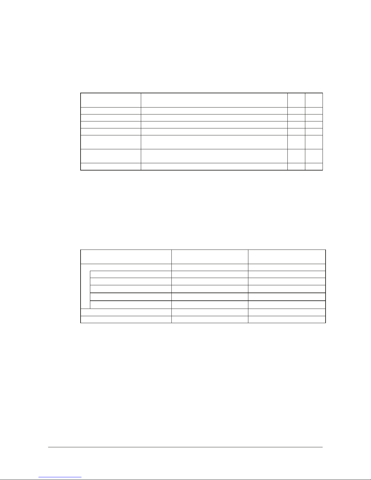
1.2 Library Configuration
The DT-X8 Software Development Kit (“BDK”) provides various libraries including those listed in
the table.
Table 1.1
Library Description C++
VB
C#
System Library Library that is used to control the system. Yes Yes
Laser Scanner Library Library that is used to control the built-in laser scan engine. Yes Yes
Bluetooth Library Library that is used to control the built-in Bluetooth module. Yes Yes
Imager Library Library that is used to control the built-in CMOS Imager. Yes Yes
JPEG Library Library that is used to handle and manipulate JPEG image
functions.
Yes -
FLINK Library Library that is used to control and carry out transmission/reception
of files between PC and other device.
Yes Yes
NFC Library Library that is used to control to communicate with IC card. Yes Yes
Note:
The abbreviations used in the table are;
C++
Visual C++
VB
Visual Basic .NET
C#
Visual C# .NET
Table 1.2 shows each file name of the Dynamic Link Library and Dynamic Link Class Library.
Table 1.2
Library Dynamic Link Library
Dynamic Link Library
(Class Library)
Common Device Control Library
System Library SystemLib.dll SystemLibNet.dll
Laser Scanner Library OBReadLib.dll OBReadLibNet.dll
Bluetooth Library BluetoothLib.dll BluetoothLibNet.dll
Imager Library ImagerLib.dll ImagerLibNet.dll
NFC Library NFCLib.dll NFCLibNet.dll
JPEG Library JpegCe.dll None
FLINK Library FlinkLib.dll MoFlinkLib.dll
7
㩷
Page 8
㩷
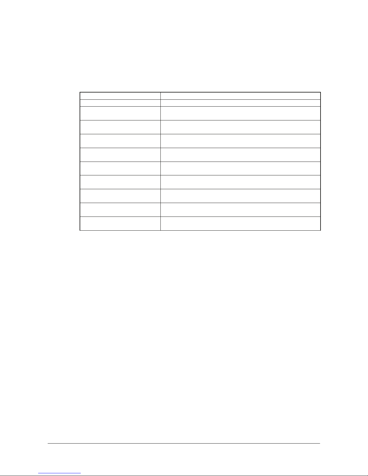
1.3 Development Manuals
The DT-X8 Software Development Kit (“BDK”) provides various development reference manuals
as described in the table below.
Table 1.3
Development Manual Description
Quick Start Guide This reference manual.
Software Manual Reference manual that describes software specifications in detail for all
the software integrated in DT-X8 handheld terminal.
Hardware Manual Reference manual that describes hardware specifications in detail on
each dedicated option and DT-X8 handheld terminal
System Library Manual Reference manual that describes individual functions in detail for System
Library.
Laser Scanner Library Manual Reference manual that describes individual functions in detail for Laser
Scanner Library.
Bluetooth Library Manual Reference manual that describes individual functions in detail for
Bluetooth Library.
Imager Library Manual Reference manual that describes individual functions in detail for Imager
Library.
JPEG Library Manual Reference manual that describes individual functions in detail for JPEG
Library.
FLINK Library Manual Reference manual that describes individual functions in detail for FLINK
Library.
NFC Library Manual Reference manual that describes individual functions in detail for NFC
Library.
8
㩷
Page 9

㩷
2. Prerequisites
2.1 Skills Required
The following skills are required by developers aiming to develop application software for the
DT-X8 terminal.
x Windows programming
x A good knowledge of one or more of the following
- Visual C++
- Visual Basic .NET
- Visual C# .NET
- Browser based applications (not covered in this guide)
The following skills or experience are also desirable.
x Windows CE devices
x ActiveSync
x Some networking experience
9
㩷
Page 10
㩷
2.2 Hardware Required
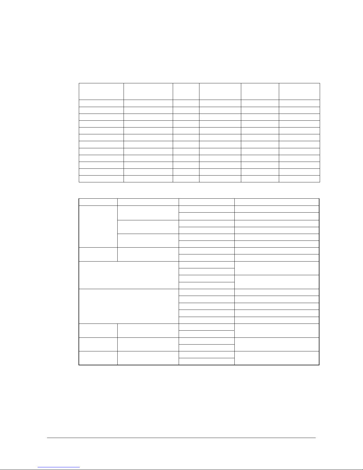
The following models of the DT-X8 series and dedicated options are available.
Table 2.1 List of available models
Model no. Scanner NFC Extension slot
WLAN
(802.11 b/g)
Bluetooth
DT-X8-10E Laser No microSD Yes Yes
DT-X8-10C-CN Laser No microSD Yes Yes
DT-X8-20E Imager No microSD Yes Yes
DT-X8-20C-CN Imager No microSD Yes Yes
DT-X8-11E Laser Yes microSD Yes Yes
DT-X8-11C-CN Laser Yes microSD Yes Yes
DT-X8-21E Imager Yes microSD Yes Yes
DT-X8-21C-CN Imager Yes microSD Yes Yes
DT-X8-40E Full range imager No microSD Yes Yes
DT-X8-40C-CN Full range imager No microSD Yes Yes
DT-X8-41E Full range imager Yes microSD Yes Yes
DT-X8-41C-CN Full range imager Yes microSD Yes Yes
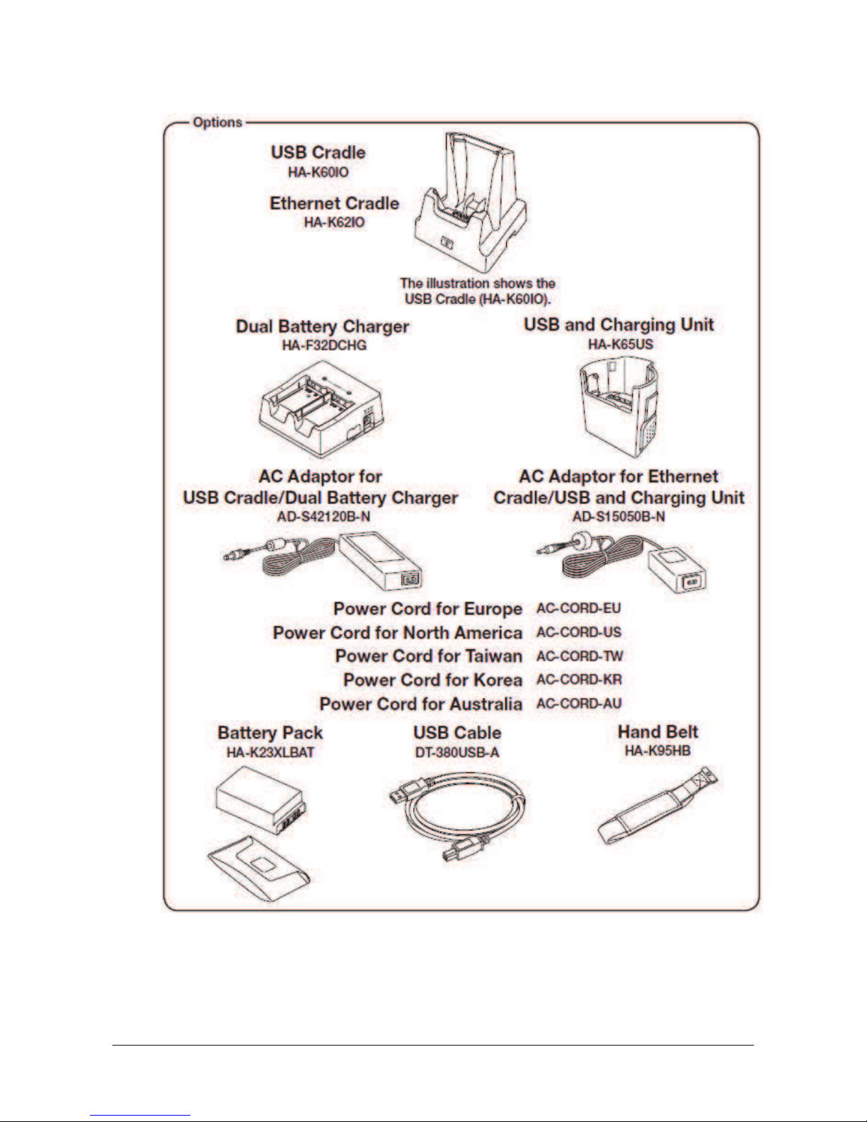
Table 2.2 List of the dedicated options
Option Product Model no. Remark
HA-K60IO USB Cradle
HA-K60IO-CN
HA-K62IO Ethernet Cradle
HA-K62IO-CN
HA-K65US
Cradle
USB and Charging Unit
HA-K65US-CN
HA-F32DCHG Battery charger Dual Battery Charger
HA-F32DCHG-CN
AD-S15050B-N
AD-S15050BE-CN
- For HA-K60IO, HA-K65US
AD-S42120B-N
AC adaptor
AD-S42120BE-CN
- For HA-K62IO, HA-F32DCHG
AC-CORD-EU - For Europe
AC-CORD-US - For USA/Canada
AC-CORD-TW - For Taiwan
AC-CORD-KR - For Korea
Power Cable for AD-S15050B-N,
AD-S42120B-N
AC-CORD-AU - For Australia/New Zealand
HA-K23XLBAT Battery Large Battery Pack
HA-K23XLBAT-CN
DT-380USB-A Cable USB cable
DT-380USB-A-CN
- For between cradle and PC
HA-K95HB Others Hand Belt
HA-K95HB-CN
Note:
“-CN” attached at the end of model number in Tables 2.1 and 2.2 denotes that the model is
dedicated for the final destination of China. A note about compliance with the Chinese “RoHS”
requirement promulgated by the Ministerial Decree No. 39 is included in the carton box; the RoHS
compliant seal is affixed on the body and the seal of the packing material recycle marking is affixed
on the carton box.
See the following pages for DT-X8 terminal external views and the dedicated options.
10
㩷
Page 11
㩷
External views of the DT-X8 and the dedicated options
Figure 2.1
11
㩷
Page 12
㩷
Figure 2.2
12
㩷
Page 13

㩷
2.3 Software Required
PC Operating System
32bit
x Microsoft Windows 2000 Professional Service Pack 4 or later
x Or Microsoft Windows 2000 Server Service Pack 4 or later
x Or Microsoft Windows XP Professional Service Pack 2 or later
x Or Microsoft Windows 2003 Server Service Pack 1 or later
x Or Microsoft Windows Vista (Business / Ultimate )
x Or Microsoft Windows 7 Service Pack 1 or later (Professional / Ultimate)
x Or Microsoft Windows Server 2008 Service Pack 1 or later
64bit
x Microsoft Windows 7 Service Pack 1 or later (Professional / Ultimate)
x Or Microsoft Windows Server 2008 Service Pack 1 or later
Development platform
The following software tools and libraries are required in order to develop software for the DT-X8.
Please ensure that you download or purchase the correct Microsoft tools as appropriate.
x Microsoft Visual Studio 2008 (not free of charge)
x Microsoft Visual Studio 2005 + Service Pack 1 (not free of charge)
x Microsoft ActiveSync 4.2 (or later)
Download for free from;
http://www.microsoft.com/downloads/details.aspx?FamilyID=7269173a-28bf-4cac-a682-58d32
33efb4c&DisplayLang=en
x Microsoft Windows Mobile Device Center 6.1 (for Windows Vista)
Download for free from;
http://www.microsoft.com/downloads/details.aspx?familyid=46F72DF1-E46A-4A5F-A791-09F
07AAA1914&displaylang=en
CASIO DT-X8 BDK
Download the DT-X8 BDK from;
http://www2.casio.co.jp/system_en/pa/PADealer/
(The site requires your user name and password. Enter your user name and password as issued by CASIO.)
13
㩷
Page 14

㩷
3. Installing BDK to PC
3.1 Application Development
This chapter explains about what you need to set up for the development environment before
starting your application development.
1. Installing Development Platform
Install Microsoft’s development platform which supports Visual Studio 2008 and Visual Studio
2005. For detail, refer to Chapter 2.3 “Software Required”.
2. Installing CASIO BDK to PC
Install Casio’s BDK (“Basic Development Kit”) and various libraries if necessary. For
installation method, refer to Chapter 3.2 “Installing CASIO BDK Files”.
3. Connecting DT-X8 to PC (via either ActiveSync or Windows Mobile Device Center)
Connect the DT-X8 to PC via Microsoft’s ActiveSync (for Windows XP or any other OS before
Windows XP) or via Windows Mobile Device Center (for Windows Vista or later). For
connection method, refer to Chapter 5 “Connecting the DT-X8 to PC”.
4. Setting up the Development Environment
Transmit the Casio’s libraries to the DT-X8.
For detail, refer to Chapter 6 “Setting Up the Development Environment”.
5. Installing the Device Emulator
Install the Device Emulator for the DT-X8. For installation method, refer to Chapter 7 “Device
Emulator”. If not necessary to install, go to “6. Application Development” below.
6. Application Development
Now, the application development environment is set up and your development with the
development platform can be started. After application is developed, transfer it to the Device
Emulator or an actual terminal of the DT-X8 via ActiveSync or Windows Mobile Device Center
for check on the operability. For application development method and transferring your
application, refer to Chapter 8 “Visual Studio”.
14
㩷
Page 15

㩷
3.2 Installing CASIO BDK Files
Download the CASIO DT-X8 BDK installation CD image file from the following site and write it to
a CD-ROM media.
http://www2.casio.co.jp/system_en/pa/PADealer/
(The site requires your user name and password. Enter your user name and password as issued by CASIO.)
Notes:
x If you had already installed DT-X8 BDK Ver. 1.xx, be sure to uninstall it before installing Ver.
2.xx.
x If any file of the DT-X8 BDK Ver. 1.xx is remained in the following folders after uninstalling,
delete it manually.
C:\Program Files\CASIO\MBSYS
C:\Program Files\Windows CE Tools\wce500
x If your PC runs in the Windows Vista or later OS, first you must disable the User Account
Control (“UAC”) by following the process below before installing the CASIO BDK Files.
Case of using Windows Vista and Windows Server 2008
- Navigate to Control Panel ĺ User Accounts ĺ Enable or Disable the User
Account Control. Remove the check on User Account Control (UAC) to protect
your PC, and then click OK button.
Case of using Windows 7
- Navigate to Control Panel ĺ User Accounts ĺ Change User Account Control
Settings. Select Never notify in Choose when to be notified about changed to your
computer setting.
15
㩷
Page 16
㩷
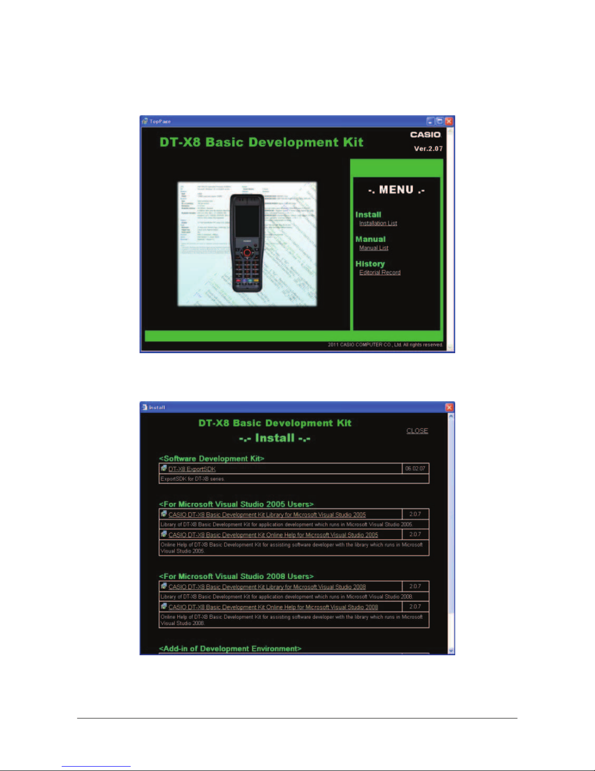
Installing ExportBDK
1. When the CASIO DT-X8 BDK CD-ROM is inserted in the drive of PC, the following menu
screen appears automatically.
Figure 3.1
2. Click Installation List in Figure 3.1. The installation screen appears.
Figure 3.2
3. Click DT-X8 ExportSDK to display the Setup Wizard. Choose any one of the buttons in the
screen.
16
㩷
Page 17

㩷
Installing Library
The DT-X8 Library is available for the below development platforms.
x Microsoft Visual Studio 2008
x Microsoft Visual Studio 2005
Notes:
1. The Library header file (*.h) and the Import library file (*.lib) are installed in the following
folder.
C:\Program Files\CASIO\MBSYS\include : Header file
C:\Program Files\CASIO\MBSYS\lib\ARMV4I : Import library file
2. The Class library DLL file (*.dll) is installed in the following folder.
C:\Program Files\CASIO\MBSYS\WindowsCE
3. When the Library is installed in PC, the Help file (*.chm) is installed in the following folder.
C:\Program Files\CASIO\MBSYS\HELP
The Help file can be accessed by navigating to Start menu o All Programs o CASIO Basic
Development Kit o Help.
Installing Online Help
Besides the Help file described above, the Online Help is also available for the below development
platforms. The installation of the Online Help is initiated in the Installation List.
x Microsoft Visual Studio 2008
x Microsoft Visual Studio 2005
After the installation is complete, Microsoft Visual Studio starts up. The Online Help file can be
accessed by navigating to Help ĺ Contents menu.
Installing Sample Program
When the Sample is chosen in the Installation List, the sample program folder in the CD-ROM
appears on the screen. The Sample program folder is available for the development platforms below.
Copy it into your PC.
- VS2008 for Microsoft Visual Studio 2008
- VS2005 for Microsoft Visual Studio 2005
If your sample program is with "Read-only" attribute set effect. Be sure to disable the attribute
before using it.
17
㩷
Page 18

㩷
4. Connecting Power Supply to Cradle
4.1 HA-K60IO
Use the dedicated AC adaptor (AD-S15050B) for supplying power to the HA-K60IO USB Cradle.
Ensure that you connect the AC adaptor to the cradle before starting communication between the
DT-X8 and PC via the cradle. Follow the steps below to connect the power supply to the DT-X8
using the dedicated AC adaptor.
1. Plug the AC adaptor into the AC adaptor jack where “DCIN5V” is printed on the back of the
cradle.
2. After connecting the power cable to the AC adaptor, plug in the plug to an electrical outlet.
3. Connect a USB cable (DT-380USB-A) to the USB port on the back of the cradle, and then
connect the other end of the cable to the PC.
4. Align the USB cradle mount holes on the back of the DT-X8 with the mount hooks on the cradle
after aligning the contacts on the bottom of the DT-X8 with the power contacts of the cradle. The
power LED on the front of the cradle will light green if the DT-X8 has been properly mounted.
Status of Indicator 1 on DT-X8
Orange : Charging
Red : Standby due to battery pack error or the surrounding temperature is out of the range (charging
begins when the temperature returns within the correct range.)
Green : Charging complete
Notes:
x Never short the power contacts of the cradle. This damages the cradle.
x Do not subject the DT-X8 and cradle to vibration or impact during communication. This results
in communication being interrupted.
x When mounting the DT-X8, securely attach it to the mount hooks of the cradle and check that
the power LED on the front of the cradle lights green. Charging the battery pack or
communication will not proceed if it is not mounted properly.
18
㩷
Page 19

㩷
4.2 HA-K62IO
Use the dedicated AC adaptor (AD-S42120B) for supplying power to the HA-K62IO Ethernet
Cradle. Ensure that you connect the AC adaptor to the cradle before starting communication
between the DT-X8 and PC via the cradle. Follow the steps below to connect the power supply to
the DT-X8 using the dedicated AC adaptor.
1. Plug the AC adaptor into the AC adaptor jack on the back of the Ethernet Cradle.
2. After connecting the AC adaptor to the power cable, plug in the plug of the power cable to an
electrical outlet.
3. Set the selector switch on the back of the Ethernet cradle to the port that will be used. Set the
switch to “LAN” to use the LAN port or to “USB” to use the USB port.
4. Before using the cradle ports, remove the caps from the ports. When using a LAN, connect one
end of the LAN cable to the LAN port and the other end to the PC or hub. When using a USB
connection, connect one end of the USB cable (DT-380USB-A) to the USB port and the other
end to the PC.
5. Align the contacts on the underside of the DT-X8 with the power supply contacts on the Ethernet
Cradle and then set the DT-X8 into the cradle so that mount holes in the back of the DT-X8 are
aligned with the mount hooks on the cradle. Once the DT-X8 is properly set in the cradle, the
power LED on the front of the Ethernet cradle lights green.
Status of Indicator 1 on DT-X8
Orange
Charging
Red
Standby due to battery pack error or the surrounding temperature is out of range
(charging begins when the temperature is within the correct range.)
Green
Charging complete
Notes:
x Always remove the DT-X8 from the Ethernet Cradle before changing the selector switch setting.
x Never short out the power contacts of the cradle. This damages the cradle.
x Do not subject the DT-X8 and cradle to vibration or impact during communication. This results
in communication being interrupted.
x When mounting the DT-X8, securely attach it to the mount hooks of the cradle and check that
the power LED on the front of the cradle lights green. Charging battery pack or communication
will not proceed if it is not mounted properly.
x The LAN and USB connections cannot be used concurrently.
x Always cap ports that are not being used. Using the Ethernet Cradle while the ports are
uncapped can cause damage.
19
㩷
Page 20

㩷
5. Connecting the DT-X8 to PC
To make connection establishment with PC, use one of the methods, depending on the OS your PC
runs, described below.
x ActiveSync (for Windows XP or any other OS earlier)
Use the ActiveSync to connect the DT-X8 to PC if the PC runs in Windows XP or other OS
earlier than Windows XP. The ActiveSync can be downloaded at the URL below.
http://www.microsoft.com/downloads/details.aspx?FamilyID=7269173a-28bf-4cac-a682-58d32
33efb4c&DisplayLang=en
x Windows Mobile Device Center (for Windows Vista or later)
Use the Windows Mobile Device Center to connect the DT-X8 to PC if the PC runs in Windows
Vista OS. The Windows Mobile Device Center (“WMDC”) can be downloaded at the URL
below.
http://www.microsoft.com/downloads/details.aspx?familyid=46F72DF1-E46A-4A5F-A791-09F
07AAA1914&displaylang=en
20
㩷
Page 21

㩷
5.1 ActiveSync Connection via USB
If you have already installed ActiveSync and connected the DT-X8 to the PC via direct USB, You
may skip Chapter 5.1.1. You already have the USB driver and ActiveSync in your development
environment. If you do not yet have the cradle driver on your PC, download the USB driver files
“wceusbsh.inf” and “wceusbsh.sys” from the CASIO web site and copy them to an appropriate
folder.
21
㩷
Page 22

㩷
5.1.1 Installing ActiveSync for the First Time
1. Install ActiveSync first. Run the ActiveSync ‘msi’ file.
Figure 5.1
2. Click I
nstall button.
Figure 5.2
22
㩷
Page 23

㩷
3. Pause the installation when the menu in Figure 5.3 is displayed; you have to install the driver at
this point.
Figure 5.3
4. Connect the USB cable to the PC and the other end to the USB Cradle and also the AC adaptor to
the USB Cradle.
5. Put the DT-X8 on the cradle and confirm that the green LED on the front of the cradle is lit. If not,
be sure the DT-X8 is positioned firmly on the cradle.
6. When the DT-X8 is mounted on the USB Cradle, a dialog is displayed to prompt you to install
the suitable driver. If you have not yet obtained the driver files, see page 16 for detail of what you
need to download.
7. Choose No, not this t
ime radio button in Figure 5.4 and then click Next > button.
Figure 5.4
23
㩷
Page 24

㩷
8. Then, choose Install from a list or s
pecific location [Advanced] radio button in the menu.
Figure 5.5
9. Click N
ext > button.
Figure 5.6
24
㩷
Page 25

㩷
10. Choose Windows CE USB Devices icon.
Figure 5.7
11. Click H
ave Disk… button.
Figure 5.8
12. Click B
rowse… button. Select “wceusbsh.inf” from the folder you created in step 6.
Figure 5.9
25
㩷
Page 26

㩷
13. The installation of the driver will start.
Figure 5.10
14. Click C
ontinue Anyway button.
Figure 5.11
15. A menu might be displayed to prompt you to install “wceusbsh.sys”. This happens if
“wceusbsh.sys” is not in the same folder as “wceusbsh.inf”. Download this file from the CASIO
Web Site and follow the prompts to specify the location of “wceusbsh.sys”.
26
㩷
Page 27

㩷
16. Now the installation of the driver is finished.
Figure 5.12
17. Now go back to the ActiveSync Installation Wizard that you left on the desktop. Click N
ext >
button.
Figure 5.13
27
㩷
Page 28

㩷
18. Now the connection is established. You can choose either partnership option according to your
needs. Then click N
ext > button.
Figure 5.14
19. Now the connection is completed. You can start up Visual Studio and create a program and
deploy it to the DT-X8.
Figure 5.15
28
㩷
Page 29

㩷
5.1.2 If ActiveSync Is Already Installed
This is the procedure if ActiveSync is already installed on the PC. You just need to let the PC
recognize the DT-X8 and install the cradle driver as in steps 6 to 16 in Chapter 5.1.1.
1. Navigate to File ĺ Connection Settings…. from the menu in ActiveSync. See Figure 5.16.
Figure 5.16
2. Check Allow U
SB connection with this desktop computer. USB is available.
Figure 5.17
29
㩷
Page 30

㩷
3. On the DT-X8, in Control Panel, choose the PC Connection option. Confirm that PC
Connection is set to “USB Default”. If not, choose ‘USB Default’ and tap OK button.
Figure 5.18
4. When the DT-X8 is mounted on the USB Cradle, a menu to prompt to install the driver is
displayed. Follow the same steps in Chapter 5.1.1.
Figure 5.19
30
㩷
Page 31

㩷
5.2 USB Connection via Windows Mobile Device Center
To establish connection via USB interface with PC runs in Windows Vista, use Windows Mobile
Device Center (“WMDC”). The DT-X8 with the factory-setting (default) does not support the
WMDC. Follow the procedure below to change the setting on the DT-X8.
Procedure
1. Close all applications running on the DT-X8.
2. Navigate to Settings o Control Panel o USB Connection.
3. Click Connect Utility tab.
Figure 5.20
4. Choose Windows Mobile Device Center radio button and then click OK button.
Figure 5.21
gue asking your final confirmation appears. Click Y
31
5. A dialo
ES button.
Figure 5.22
-X8 starts up again.
. Mount the DT-X8 on the cradle, and then follow a message appeared in the WMDC on the PC.
6. The DT
7
㩷
Page 32

㩷
Notes:
x To resume the factory default setting, choose ActiveSync/LMWIN radio button in Step 3 on
the previous page (see Figure 5.20), and start up the DT-X8 again.
x The WMDC version 6.1 or later will support the connection establishment via USB interface.
Any other versions of the WMDC earlier are not interoperable with Windows CE devices
including the DT-X8 series.
32
㩷
Page 33

㩷
5.3 Connection via WLAN
To establish communication between the DT-X8 with the WLAN module integrated (see Table 2.1
for the applicable models) and PC via WLAN configuration, follow the steps, 1 to 6, below to set up
a WLAN configuration on the DT-X8. After setting up the configuration, be sure to perform a site
survey prior to starting communication via WLAN.
1. Navigate to Start o S
ettings o Ctrol Panel o WLANConfig and then click IP tab.
Figure 5.23
Table 5.1
Parameter Description
Enable DHCP or Configure IP Determines “Enable” or “Disable” for DHCP.
IP Determines IP address.
MASK Determines subnet mask.
GateWay Determines default gateway.
DNS1 Determines primary DNS address.
DNS2 Determines secondary DNS address.
WINS1 Determines primary WINS address.
WINS2 Determines secondary WINS address.
If any of the settings in Figure 5.23 is omitted, the process described in the following table will
automatically take place in the field.
Table 5.2
Parameter Nothing is set (DHCP) “Configure IP” is set
Enable DHCP or
Configure IP
“Enable DHCP” is assumed. “Configure IP” is set.
IP Does not determine IP address. Entered address is set as is.
MASK Does not determine subnet mask. Entered address is set as is.
GateWay Does not determine gateway. Entered address is set as is.
DNS1 Does not determine primary DNS address. Entered address is set as is.
DNS2 Does not determine secondary DNS address. Entered address is set as is.
WINS1 Does not determine primary WINS address. Entered address is set as is.
WINS2 Does not determine secondary WINS
address.
Entered address is set as is.
33
㩷
Page 34

㩷
2. Click Basic tab. Set up each parameter in the tab by referring to the descriptions for the
parameters in Table 5.3.
Figure 5.24
Table 5.3
Parameter Description
SSID Enter the SSID of the network you want to connect to.
Disable None.
WEP Open in Authentication field.
Security
WPA PSK in Authentication field (if selected, the Key field must be set also.)
EAP-PEAP in Authentication field
EAP-TLS in Authentication field
Key Enter 26 (maximum) alphanumeric digits (13 hex pairs) in the Key field if 128 bit
radio button is selected. Or, enter 10 (maximum) alphanumeric digits (5 hex pairs) in
the Key field if 64 bit radio button is selected.
The field displays the number of characters that have been entered.
***** in the field implies that the key has been extracted from the ini file. If ***** in
the field is edited, a new key has been deemed to be set. Or, if it has never been edited,
the key extracted from the ini file becomes effective as is.
If EAP-PEAP radio button in Authentication field is selected, click the EAP-Properties button
that appears when selecting the EAP-PEAP radio button to set also the following parameters.
Table 5.4
Parameters in
EAP-Properties screen
Description Default
User name Input a user name in alphanumeric (maximum 100
alphanumeric).
None
Password Input a password in alphanumeric (maximum 100
alphanumeric).
***** in the field implies that the password has been
extracted from the ini file. If ***** in the field is
edited, a new password has been deemed to be set.
Or, if it has never been edited, the password extracted
from the ini file becomes effective as is.
None
Domain Input a domain in alphanumeric (maximum 100
alphanumeric).
None
Validate server
certificate
Set up the requisition for server certificate.
With check mark : certificate is required.
Without check mark: certificate is not required.
Certificate is not necessary
34
㩷
Page 35

㩷
If EAP-TLS radio button in Authentication field is selected, click the EAP-Properties button that
appears when selecting the EAP-TLS radio button to set the following settings.
Table 5.5
Parameters in
EAP-Properties screen
Description Default
User name Input a user name in alphanumeric (maximum 100
alphanumeric).
None
Certificate Select a client certificate installed already (maximum
100 alphanumeric).
Search button in the field will display a list of
installed client certificates. Select one by highlighting
it.
None
Domain Input in alphanumeric (maximum 100 alphanumeric) None
Validate server
certificate
Set up the requisition for server certificate.
With check mark : certificate is required.
Without check mark : certificate is not required.
Certificate is required.
3. Click WLAN tab.
Figure 5.25
Table 5.6
Field / Radio
Buttons
Description Default
On Enable power to the integrated WLAN module. Yes Adapter power
Off Disable power to the integrated WLAN module.
Enable Enable power save mode for the WLAN module. Yes Power save
Disable Disable power save mode for the WLAN module.
b Set up IEEE802.11b standard effect. Standard
b/g Set up IEEE802.11b/g standard effect. Yes
No roaming Set up “-100 dBm” for roaming starting threshold level,
a level where communication via WLAN is practically
impossible, so that roaming should not be carried out.
Default Set up “-78 dBm” for the roaming starting threshold
level.
Yes
RSSI Level for
initiating roaming
High Set up “-72 dBm” for roaming starting threshold level,
for faster (more frequent) roaming
35
㩷
Page 36

㩷
4. Click Detail tab.
Figure 5.26
Table 5.7
Field / Radio Buttons Description Default
WLANConfig,
NetSearch
- Use only CASIO provided WLAN tool.
- Configure WLAN setting with settings
extracted from the ini file.
- Initiate NetSearch when tapping the icon in
the task tray.
Yes
WLANConfig,
NetUI
- Use both CASIO provided WLAN tool and
MS tool.
- Configure WLAN setting with settings
extracted from the ini file.
- Initiate NetUI (MS tool) when tapping the
icon in the task tray.
WLAN configure,
Status display tool
NetUI/NetUI - Use only the MS tool.
- Configure WLAN setting, not with settings
extracted from the ini file.
- Initiate NetUI when tapping the icon in the
task tray.
If this radio button is selected and the OK button
that appears in the subsequent popup warning
message is clicked, other settings in the ini file
will be deleted. Only the WLAN configuration
set with NetUI is saved.
With check mark : enable the setting. Enable AdHoc network setting
Without check mark : disable the setting. Yes
With check mark : enable the setting. Enable all authentication settings
Without check mark : disable the setting. Yes
Inifile comment Enter a comment of up to 100 characters to be
written in the ini file.
None
36
㩷
Page 37

㩷
5. If OK button in the popup warning message (see Table 5.7 for description of NetUI/NetUI radio
button) is clicked, the screen in Figure 5.27 appears. Click OK button to perform a reset on the
terminal so that the setting takes effect.
Figure 5.27
6. Check to make sure that the connection has been established using the NetSearch utility, and
then navigating to the Ping function in there. Enter HostName first and then click Ping to check
that you are connected to the network correctly.
37
㩷
Page 38

㩷
5.4 Connection via Ethernet Cradle
This chapter describes how to establish a high speed LAN connection on the WLAN non-integrated
models with HA-K62IO Ethernet cradle.
Follow the steps below:
1. Connect the dedicated AC adapter to the Ethernet cradle as described in Chapter 4.2.
2. Connect one end of the network cable to the Ethernet cradle and the other end to the network hub.
3. Make sure the selector switch on the back of the HA-K62IO Ethernet cradle is set to the position
“LAN”.
4. Place the DT-X8 in the cradle and navigate to Start o S
ettings o Control Panel o
Network and Dial-up Connections.
5. The following screen appears. Double click the AX887721 icon. The icon will not appear unless
the terminal is placed in the cradle.
Figure 5.28
38
㩷
Page 39

㩷
6. The following TCP/IP screen appears. Set up all the parameters in IP Address and Name
Servers tabs as required and click OK button.
Figure 5.29
7. If the connection is established correctly, the icon (
) in the Taskbar changes to ( ).
39
㩷
Page 40

㩷
5.5 Accessing Shared Network Drive on Your LAN
Assuming you have a valid network connection established, you can access shared drives on your
PC from the File Explorer on the DT-X8. The following shows the steps to initiate this.
1. Configure a network connection on the DT-X8.
2. Double click My Computer.
3. Type \\xxxx\ where xxxx is the network name of the PC.
4. A network logon dialog box will appear. Enter a valid User ID, Password and Network
Domain.
5. Any shared network drives on the target PC will be displayed and you will be able to copy files
freely between them and the DT-X8.
40
㩷
Page 41

㩷
5.6 Direct TCP/IP Connection from Visual Studio
If you have a network connection to the DT-X8 (for example, via WLAN or the Ethernet cradle)
then you can establish a direct link to the development PC without using ActiveSync.
For Visual Studio 2005
1. Download the files listed below to the DT-X8.
- Clientshutdown.exe
- ConmanClient2.exe
- CMAccept.exe
- DeviceDMA.dll
- eDbgTL.dll
- TcpConnectionA.dll
The source folder in the PC:
C:\Program Files\Common Files\Microsoft Shared\CoreCon\1.0\Target\wce400\armv4i
The destination folder in the DT-X8:
\Windows
2. Run ConmanClient2.exe on the DT-X8.
3. Set the device IP address in Visual Studio 2005.
4. Navigate to Tools in the main menu of Visual Studio 2005 o Options… o Device Tools
o Devices.
5. Choose DT-X8 Device in the pull-down menu of Devices: and click Properties….
6. Click Transport: to access Configure… and set up Device IP address as shown in Figure
5.30.
Figure 5.30
7. Run CMAccept.exe on the DT-X8.
8. Navigate to Tools in the main menu of Visual Studio 2005 o Connect to Device….
41
㩷
Page 42

㩷
9. Choose DT-X8 Device in the list of Devices: and click Connect button. The screen in Figure
5.31 if appear indicates the success of connection establishment.
Figure 5.31
42
㩷
Page 43

㩷
6. Setting Up the Development Environment
6.1 Installing CAB Files
1. After installing the library files, the CAB files in Table 6.1 will be installed in the folder
below.
C:\Program Files\CASIO\MBSYS\CAB
Table 6.1
Library CAB file Preinstalled
System Library en_SystemLib.ARMV4I.CAB Yes
Laser Scanner Library en_OBReadLib.ARMV4I.CAB Yes
Bluetooth Library en_BluetoothLib.ARMV4I.CAB Yes
Imager Library en_ImagerLib.ARMV4I.CAB Yes
JPEG library enJPEG.ARMV4I.CAB Yes
FLINK library en_Flink.ARMV4I.CAB Yes (note 2)
NFC Library en_NFCLib.ARMV4I.CAB Yes
Notes:
1. The library with "Yes" in "Preinstalled" column is preinstalled in the DT-X8 and in the
Device Emulator. Thus, it is not necessary to install it, unless it has been updated or
changed.
2. The CAB file, en_Flink.ARMV4I.CAB, in the table does not operate for the DT-X8. Use
the FlinkLib.dll installed by default in the terminal.
2. Copy all the CAB files in Table 6.1 to any folder on the DT-X8 via ActiveSync.
3. Carry out each CAB file.
4. When the installation starts, the installation status will appear.
43
㩷
Page 44

㩷
6.2 Visual Studio 2005
Follow the steps in Chapter 5 “Connecting the DT-X8 to PC” before checking the steps below to
confirm that you can connect to the DT-X8 from Visual Studio 2005.
1. Establish connection with the DT-X8 via ActiveSync.
2. Open the application project for VB or C# in Visual Studio 2005.
3. Click the button shown in the red box below (see Figure 6.1) to make sure that Visual Studio
2005 has recognized the connection established with the DT-X8 via ActiveSync. If it does not,
start up ActiveSync again to establish connection.
Figure 6.1
4. Choose DT-X8 Device in the pull-down menu box.
Figure 6.2
5. You will now be able to deploy solutions and also debug applications on the attached DT-X8
using the Visual Studio 2005 debugging features.
44
㩷
Page 45

㩷
7. Device Emulator
The Device Emulator provides application developers with an environment that, without having
the actual terminal available, allows them to debug basic functions and performance of an
application at source level by stepping through the code.
7.1 Software Required
The Device Emulator requires the software(s) listed below before installing the emulator.
x ActiveSync 4.2 or a later version (If required)
http://www.microsoft.com/downloads/details.aspx?FamilyID=7269173a-28bf-4cac-a682-58d32
33efb4c&DisplayLang=en
x Visual Studio 2008 or Visual Studio 2005 (Required)
x CASIO DT-X8 BDK (Required)
x Standalone Device Emulator 3.0 (Optional. See notes 1 and 2.)
http://www.microsoft.com/downloads/details.aspx?displaylang=en&FamilyID=a6f6adaf-12e3-4
b2f-a394-356e2c2fb114
Notes:
1. To use Microsoft Device Emulator 3.0, follow the steps below.
x Install DT-X8 ExportSDK and Device Emulator of the DT-X8 BDK.
x Download Microsoft Device Emulator 3.0 and install it.
x Edit the following file and save the changes made.
C:\Program Files\Windows CE Tools\wce600\DT-X8\Emulation\DT-X8.cdes
Before you change, the default parameter in the file is described as follows.
module=DevEmu500.exe
Change the parameter to the one below. Be sure to describe the whole parameter in single
one line.
module=C:\Program Files\Microsoft Device Emulator\1.0\
DeviceEmulator.exe
You can substitute the Device Emulator Version 3.0 released in Visual Studio 2008 for an
engine of Device Emulator included in the DT-X8 BDK by the mentioned procedure above.
45
㩷
Page 46

㩷
2. If you use Microsoft Device Emulator 3.0, you can save the status of the Device Emulator. After
the steps in Note 1 in the previous page, change the settings in "DT-X8.cdes" as follows.
Before you change, the parameter in the file is as follows.
others=/sharedfolder "C:\Documents and Settings\All
Users\Application Data\CASIO\Emulator\Ctrl" /vmname "DT-X8 Emulator"
Change the parameter to the one below. Be sure to describe the whole parameter in single one
line.
others=/sharedfolder "C:\Documents and Settings\All Users\Application
Data\CASIO\Emulator\Ctrl" /vmname "DT-X8 Emulator" /defaultsave
Case of using after Windows Vista OS
If you use OS after Windows Vista (Windows 7 or Windows Server 2008), please set device
emulation and I/O simulator as administrator.
Please check “Run this program as an administrator” of property from opening Explorer.
(Ex. Execute I/O simulator in Windows Vista as administrator.)
Figure 7.1
46
These program have installed the following location as default setting.
x Device emulator
C:\Program Files\Microsoft Device Emulator\1.0\DeviceEmulator.exe
x I/O simulator
C:\Program Files\Common Files\CASIO\Emulator\DevIoSim.exe
㩷
Page 47

㩷
7.2 Starting Up the Device Emulator
After installing all required software described in Chapter 7.1, follow the steps below to start up the
Device Emulator on your PC.
1. Navigate to Start menu o All Programs o CASIO Device Emulator and click DT-X8.
2. Make sure that the DT-X8 Device Emulator has started up on the screen. See Figure 7.2.
3. Navigate to Start menu o All Programs o CASIO Device IO Simulator and click IO
Simulator.
4. Make sure that the IO Simulator has started up on the screen. See Figure 7.3.
5. If both Figure 7.2 and Figure 7.3 appear on your PC, you are ready to use the emulator.
Note.
If do not appear "DT-X8" in "CASIO Device Emulator", please execute "Add Device".
If you use OS after Windows Vista, please execute "DevEmuLoader.exe" as administrator by
referring " Case of using after Windows Vista OS" section.
C:\Program Files\Common Files\CASIO\Emulator\DevEmuLoader.exe
Figure 7.2 DT-X8 Device Emulator Figure 7.3 I/O Simulator
Terminology of Emulator and Simulator;
The Emulator described in this reference manual is a software application that behaves in a very
similar way to the actual device by imitating individual hardware components or protocols present in
the actual hardware.
47
On the other hand, the Simulator is also a software application that logically integrates application
programming interfaces (“API”) and certain other functions to allow debugging of the application
program using external events. The Emulator performs in a pseudo CPU and hardware
environment and it is impossible for the application to recognize whether it is in the actual device
㩷
Page 48

㩷
environment or pseudo environment. However, actions carried out by the Simulator are not as
alike to those performed by actual components but merely mimic them very closely.
48
㩷
Page 49

㩷
7.3 Using the Device Emulator
7.3.1 DT-X8 Device Emulator
The DT-X8 Device Emulator emulates various operations carried out by the actual DT-X8 device
on the PC’s screen such as mouse operation, input on PC’s keyboard, displaying execution of
applications, and operations by actual devices such as the scanner. Figure 7.4 shows an emulated
DT-X8 device on the screen of a PC.
Figure 7.4
Key Input
The emulator offers key input capability similar to that of the actual DT-X8 device. For instance, a
key on the emulated keyboard of DT-X8 on the screen (see Figure 7.4) can be clicked with the PC
mouse as well as key input made directly on the PC’s keyboard.
Reading Bar Codes
The emulator enables bar codes pre-registered in the I/O Simulator (see Figure 7.3) to be input when
clicking Trigger key on the emulated keyboard (see Figure 7.4). Note however that the Trigger key
must be continuously pressed for a second or more otherwise an incorrect key input may result.
Sound
The emulator offers beep and sound capability similar to that of the actual DT-X8 device.
49
㩷
Page 50

㩷
7.3.2 I/O Simulator
The I/O Simulator simulates registration of bar codes, generation of low battery warning, detection
of terminal being mounted on the cradle.
Registration of bar code symbologies
1. Registration
Click ADD1D or ADD2D button (circled in red in Figure 7.4) to go into the bar code
registration mode.
Figure 7.5
2. Bar code registration
Choose a bar code symbology in the Code Type pull-down menu that you wish to register in
the I/O Simulator.
Figure 7.6
50
㩷
Page 51

㩷
3. Registration of bar code and note
Enter bar code data in the Code field (see Figure 7.7) and a note about the bar code in the
Note field if necessary. Click OK button to complete the bar code registration.
Figure 7.7
4. Completion of registration
After completion of the bar codes registration, the screen in Figure 7.8 shows a list of bar codes
that have been registered in the I/O Simulator. Prior to debugging with the Device
Emulator, make sure that you register all bar codes you wish to use in debugging.
Figure 7.8
51
㩷
Page 52

㩷
5. Editing registered bar code content
Highlight a bar code in the list of registered bar codes (see Figure 7.8) and click Edit button.
Figure 7.9 appears for editing the bar code and its information.
Figure 7.9
6. Deleting registered bar code content
Highlight a bar code in the list of registered bar codes (see Figure 7.8) and click the Del button.
Dialogue screen in Figure 7.10 appears for you to confirm the deletion. If it is okay to delete,
click Y
es button, otherwise click No button.
Figure 7.10
52
㩷
Page 53

㩷
Detection of Terminal in Cradle and Low Battery Warning
If you check the I/O Box and Low Battery boxes in STATE SETTING field (see Figure 7.11), the
simulator simulates the respective events in the emulator.
Figure 7.11
I/O Box
If this box is checked, a notification is issued that the connection between the DT-X8 Device
Emulator and cradle has been established. This notification can be utilized by the application.
Low Battery
If this box is checked, a notification that a low battery state has occurred is raised. The icon in the
Toolbar in the emulated screen appears too. The notification can be utilized by the application to
recognize the low battery state in the hardware.
53
㩷
Page 54

㩷
Indications
The I/O Simulator expresses a change of state that occurred in the DT-X8 Device Emulator.
x LED
When the DT-X8 Device Emulator turns on the LED, the LED icon (LED2) in the I/O Simulator also turns on.
See Figure 7.11.
x Vibration
When the DT-X8 Device Emulator vibrates, the vibration icon in the I/O Simulator also turns on. See Figure
7.11.
Figure 7.12
54
㩷
Page 55

㩷
7.3.3 Connecting via ActiveSync
If debugging with the Device Emulator is carried out in Visual Studio 2008 or Visual Studio 2005,
or transmission/reception of a file with the Device Emulator is carried out, ActiveSync must be
used.
Setting ActiveSync
1. Start up ActiveSync and then navigate to File o Connection Settings ….
Figure 7.13
2. In Connection Settings screen, check in the Allow con
nections to one of the following
box and choose DMA in the pull-down menu. See Figure 7.14.
Figure 7.14
55
㩷
Page 56

㩷
Connection via ActiveSync
The way to establish connection of the Device Emulator via ActiveSync is;
1. Start up the Device Emulator by referring to Chapter 7.2 “Starting Up the Device Emulator”.
2. Start up Visual Studio 2008 or Visual Studio 2005, and then navigate to Tools o Device
Emulator Manager. Right-click DT-X8 Emulator in Available Emulators list and then
choose Cradle in the popup menu. See Figure 7.15.
Figure 7.15
3. Make sure ActiveSync has started up and the icon in the status bar appears. See the emulated
screen of DT-X8 in Figure 7.16. The icon indicates that the connection via ActiveSync has been
established.
Figure 7.16 Figure 7.17
56
㩷
Page 57

㩷
7.4 Debugging Applications
This chapter describes how to debug your application using the Device Emulator. Before starting
to “Build”, establish a connection between the DT-X8 and your PC via ActiveSync by referring to
Chapter 7.3 “Using the Device Emulator”.
For the basic order of developing an application, refer to Chapter 8 “Visual Studio”.
Setting Build Configuration
Choose Debug in the Solution Configurations pull-down menu in Visual Studio 2008 or Visual
Studio 2005 and DT-X8 Emulator in the target device pull-down menu. See Figure 7.18.
Figure 7.18
Debugging Applications
x Basic Debug Operation
The debug operation used for the Device Emulator in Visual Studio 2008 or Visual Studio
2005 is the same as an ordinary debug operation using the actual terminal.
x Debugging with the Device Emulator
With the Device Emulator, it is possible to set a break point in the source code of the
application for step-by-step debugging.
1. Navigate to Debug menu o Start Debugging to start up the debugger.
Figure 7.19
57
㩷
Page 58

㩷
2. Similar to ordinary debugging operations with an actual DT-X8, the Device Emulator
allows break point setting (circled in red in Figure 7.20) in the source code and step-by-step
debugging.
Figure 7.20
58
㩷
Page 59

㩷
8. Visual Studio
This chapter describes application development steps in Visual Studio 2008 or Visual Studio 2005 to
create an example program. The example program referred to in this chapter is an application
program developed in three development environments - C++, Visual Basic and C# - using the
CASIO Common Device Control Library or Common Device Control Class Library. The example
program for all three environments repeats turning on and off the LED to brink for a period of 5
seconds. See Chapters 8.1 “Developing in C++”, 8.2 “Developing in VB” and 8.3 “Developing in
C#” for each development environment.
For the list of the libraries provided by the DT-X8 BDK, refer to Chapter 1.2 “Library
Configuration”. For detail about each function of the Common Device Control Library and Common
Device Control Class Library, refer to Common Device Control Library Manual.
The example program in this chapter runs also in the Device Emulator. To use the emulator, rename
DT-X8 Device to DT-X8 Emulator.
Notes:
x Functions of the Common Device Control Library which control various individual devices
integrated in the DT-X8 have different name spaces and names from those available for the
previous CASIO handheld terminals. They are not compatible with the ones in the previous
CASIO library. The exceptions are DT-X7, DT-X11, and IT-600 that use the same libraries.
x Applications developed with any functions of CASIO dedicated library must be rewritten by
replacing the dedicated functions with the appropriate functions from the Common Device
Control Library.
x Take care when using Visual Studio 2008 or Visual Studio 2005 to upgrade an existing
application and always keep a backup of your existing project.
59
㩷
Page 60

㩷
8.1 Developing in C++
This chapter describes necessary steps to develop the example application program (see Chapter 8)
in C++ environment using the Common Device Control Library.
Before proceeding to creating the project, check if the installation folder for the Common Device
Control Library has been registered in Visual Studio 2008 or Visual Studio 2005 by following steps,
1 to 8, below.
1. Navigate to Tools ĺ Options … and open Options screen.
2. Navigate to Projects and Solutions ĺ Directories.
3. Choose DT-X8 (ARMV4I) in Platforms.
4. Choose Include files in Show directories for:.
5. If the installation folder has not been registered, append the following.
C:\Program Files\CASIO\MBSYS\include
6. Choose Library files in Show directories for:.
7. If the files have not been registered, append the following.
C:\Program Files\CASIO\MBSYS\lib\ARMV4I
8. Click OK button to close the screen.
Application Development Procedure
Subsequent steps show how to create and start up a simple program using one of the system
functions. When running the program, the LED will blink in red for 5 seconds.
1. First, create Win32 Smart Device Project with its device name DeviceApp for Visual C++
in Visual Studio 2008 or Visual Studio 2005.
2. Choose Pocket PC 2003 in the Selected BDKs field in the Platforms of Win32 Smart Device
Project Wizard and click < button.
Figure 8.1
60
㩷
Page 61

㩷
3. Choose DT-X8 in the Installed BDKs (SDKs in the screen) field and click > button.
Figure 8.2
4. Click Next > button while DT-X8 is kept being highlighted in the S
elected BDKs (SDKs in
the screen) field.
Figure 8.3
5. Choose Console Application for the Application type in the Application Settings menu, and click
Finish button.
6. In Solution Explorer, click DeviceApp.cpp and then append the source code below subsequent
to “#include <commctrl.h>”.
#include <SystemLib.h>
#if !defined(_countof)
#define _countof(_Array) (sizeof(_Array) / sizeof(_Array[0]))
#endif
61
㩷
Page 62

㩷
7. Append the source code below in the main function of DeviceApp.cpp.
DWORD result;
TCHAR msg[16];
result = SysSetLED(LED_RED, 5, 8, 8);
if(result == TRUE)
{
result = SysGetLED();
switch(result & 0x0000000F) {
case LED_OFF:
wcscpy_s( msg, _countof(msg), TEXT("LED_OFF") );
break;
case LED_RED:
wcscpy_s( msg, _countof(msg), TEXT("LED_RED") );
break;
case LED_GREEN:
wcscpy_s( msg, _countof(msg), TEXT("LED_GREEN") );
break;
case LED_ORANGE:
wcscpy_s( msg, _countof(msg), TEXT("LED_ORANGE") );
break;
case LED_BLUE:
wcscpy_s( msg, _countof(msg), TEXT("LED_BLUE") );
break;
case LED_CYAN:
wcscpy_s( msg, _countof(msg), TEXT("LED_CYAN") );
break;
case LED_MAGENTA:
wcscpy_s( msg, _countof(msg), TEXT("LED_MAGENTA") );
break;
default:
wcscpy_s( msg, _countof(msg), TEXT("LED_UNKNOWN") );
break;
}
MessageBox(NULL, msg, TEXT("LED"), MB_OK);
}
62
㩷
Page 63

㩷
8. Choose Properties in the Project of Visual Studio 2008 or Visual Studio 2005, and navigate to
Configuration Properties o Linker o Input o Additional Dependencies and then
append SystemLib.lib (see red circle in Figure 8.4).
Figure 8.4
9. Choose DT-X8 Device for the Target Device to establish connection with the PC.
10. Choose Debug in Visual Studio 2008 or Visual Studio 2005 and then click either Start Debugging
or Start Without Debugging.
11. The project will be built and copied to the “\Program Files\<name of project>” folder by default
in the DT-X8.
12. Check that the program runs correctly on the DT-X8.
63
㩷
Page 64

㩷
8.2 Developing in VB
This chapter describes necessary steps to develop the example application program (see Chapter 8)
in VB environment using the Common Device Control Class Library.
Application Development Procedure
Subsequent steps show how to create and start up a simple program using one of the system
functions. When running the program, the LED will blink in red for 5 seconds.
1. Create a new VB Smart Device Application in Visual Studio.
2. In Solution Explorer, right-click References and click Add Reference…
3. Click Browse and navigate to the folder where you have stored the CASIO .NET library files.
Highlight SystemLibNet.dll and click it to open. Click OK button.
Figure 8.5
4. Add a button to the form, rename it LED, and double click it.
64
㩷
Page 65

㩷
5. In the event function for the button to click, add the following code.
Dim result As Int32
Dim msg As String
result = Calib.SystemLibNet.Api.SysSetLED( _
Calib.SystemLibNet.Def.LED_RED, 5, 8, 8)
'.NET vales of “true” and “false” are “-1” and “0” respectively.
If result = -1 Then
result = Calib.SystemLibNet.Api.SysGetLED()
Select Case (result And &HF)
Case Calib.SystemLibNet.Def.LED_OFF
msg = "LED_OFF"
Case Calib.SystemLibNet.Def.LED_RED
msg = "LED_RED"
Case Calib.SystemLibNet.Def.LED_GREEN
msg = "LED_GREEN"
Case Calib.SystemLibNet.Def.LED_ORANGE
msg = "LED_ORANGE"
Case Calib.SystemLibNet.Def.LED_BLUE
msg = "LED_BLUE"
Case Calib.SystemLibNet.Def.LED_CYAN
msg = "LED_CYAN"
Case Calib.SystemLibNet.Def.LED_MAGENTA
msg = "LED_MAGENTA"
Case Else
msg = "LED_UNKNOWN"
End Select
MessageBox.Show(msg, "LED")
End If
Note:
If you type this code manually you should see the IntelliSense offer you suitable options as
appropriate. If you do not, make sure you review steps 1 to 5 to make sure you have added the
reference correctly.
6. Initiate ActiveSync to establish connection between the DT-X8 and PC.
7. Choose Deploy <name of project> on Build menu.
8. The project will be built and copied to the DT-X8. By default, it will be copied to \Program
Files\<name of project> folder. SystemLibNet.dll will be deployed to the same folder.
9. Check that the program works correctly on the DT-X8.
65
㩷
Page 66

㩷
8.3 Developing in C#
This chapter describes necessary steps to develop the example application program (see Chapter 8)
in C# environment using the Common Device Control Class Library.
Application Development Procedure
Subsequent steps show how to create and start up a simple program using one of the system
functions. When running the program, the LED will blink in red for 5 seconds.
1. Create a new C# Smart Device Application in Visual Studio .NET.
2. In Solution Explorer, right click References and click Add Reference…
3. Click Browse and navigate to the folder where you have stored the CASIO .NET library files.
Highlight SystemLibNet.dll and click Open. Click OK button.
Figure 8.6
4. At the top of your source file add the following code.
using Calib;
66
㩷
Page 67

㩷
5. Add a button to your form, rename it LED and double click it and then add the following code:
Int32 result = new Int32();
string msg;
result = SystemLibNet.Api.SysSetLED(SystemLibNet.Def.LED_RED, 5,
8, 8);
// .Net values “true” and “false” are “-1” and “0” respectively.
if(result == -1)
{
result = SystemLibNet.Api.SysGetLED();
switch(result & 0x0000000F)
{
case SystemLibNet.Def.LED_OFF:
msg = "LED_OFF";
break;
case SystemLibNet.Def.LED_RED:
msg = "LED_RED";
break;
case SystemLibNet.Def.LED_GREEN:
msg = "LED_GREEN";
break;
case SystemLibNet.Def.LED_ORANGE:
msg = "LED_ORANGE";
break;
case SystemLibNet.Def.LED_BLUE:
msg = "LED_BLUE";
break;
case SystemLibNet.Def.LED_CYAN:
msg = "LED_CYAN";
break;
case SystemLibNet.Def.LED_MAGENTA:
msg = "LED_MAGENTA";
break;
default:
msg = "LED_UNKNOWN";
break;
}
MessageBox.Show( msg, "LED");
}
Note:
If you add this code manually you should see the IntelliSense offer you suitable options as
appropriate. If you do not see this, then review steps 2 to 4 in the previous page to make sure you
have not made a mistake.
67
㩷
Page 68

㩷
6. Initiate ActiveSync to establish connection between the DT-X8 and PC.
7. Select Deploy <name of project> on Build menu.
8. The project will be built and copied to the DT-X8. By default, it will be copied to \Program
Files\<name of project> folder. SystemLibNet.dll will be deployed to the same folder.
9. Check that the program works correctly on the device.
68
㩷
Page 69

㩷
9. Resources
Microsoft’s own
http://msdn.microsoft.com/mobility/ is an extremely comprehensive resource for
programmers targeting WindowsCE .NET based devices. It includes links to most other useful web
based resources. You will find detailed Software and Library manuals on
http://world.casio.com/system/pa.
69
㩷
 Loading...