

Casio DT-X11M10E, DT-X11M10RC-CN, DT-X11M30E, DT-X11M30U, DT-X11M10RC Quick Start Manual
...Page 1

DT-X11 Series
Quick Start Guide
(Version 1.03)
CASIO Computer Co., Ltd.
Copyright ©2009. All rights reserved.
January 2009
Page 2

2
Table of Contents
Editorial Record 4
Preface 5
Chapter 1. Product Overview
6
1.1 Hardware Specifications 6
1.2 Library Configuration 9
1.3 Developmen
t Reference Manuals 10
1.4 Sample Program 11
Chapter 2. Prerequisites 12
2.1 Skills Required 12
2.2 Hardware Required 13
2.3 Software Required 17
Chapter 3. Setting Up the Development Environment 18
3.1 Application Development 18
3.2 Installing CASIO SDK Files 19
Chapter 4. Setting Up Bridge Satellite Cradle 22
4.1 Configuring DIP S
witch Settings 24
Chapter 5. Connecting the DT-X11 to PC 25
5.1 Connection via PCMCIA or CF Card 26
5.2 Connections via ActiveS
ync 27
5.2.1 Via Direct IrDA 28
5.2.2 Via Direct USB 32
5.2.3 Through Bridge Satellite Cradle via USB 37
5.2.4 Through Bridge Satellite Cradle via RS-232C 39
5.3 Connection via Windo
w
s Mobile Device Center 41
5.4 Connection via WLAN 43
5.5 Connection via Bluetooth 45
5.6 Connection via Ethernet PC Card 47
5.7 Accessing Shared Network Drive via WLAN 48
5.8 Connection via Direct TCP/IP from Visual Studio 49
Chapter 6. Setting Up the Development Environment 50
6.1 Installing CAB Files 50
6.2 eMbedded Visual C++ 4.0 51
6.3 Visual Studio 2005 52
6.4 Visual Studio .NET 2003 53
Chapter 7. Device Emulator 54
7.1 Softw
are Required 54
7.2 Starting Up the Device Emulator 56
7.3 Using the Device Emulator 57
7.3.1 DT-X11 Device Emulator 57
7.3.2 I/O Simulator 58
7.3.3 Connecting via ActiveSync 63
7.4 Debugging Applications 66
7.4.1 Setting Build Configuration 66
7.4.2 Debugging Applications 66
Chapter 8. eMbedded Visual C++ 69
8.1 Building Simple eVC++ 4.0 Test Program 69
8.2 Using CASIO Libraries from eVC++ 4.0 71
Chapter 9. Visual Studio 73
Page 3

3
9.1 Using CASIO .NET Libraries from VB .NET 74
9.2 Using CASIO .NET Libraries from C# 76
9.3 Using CASIO Libraries from C++ 78
Chapter 10. Resources 82
Chapter 11. Troubleshooting 83
No part
of this document may be produced or transmitted in any form or by any means, electronic or
mechanical, for any purpose, without the express written permission of CASIO Computer Co., Ltd.
in Tokyo Japan. Information in this document is subject to change without advance notice. CASIO
Computer Co., Ltd. makes no representations or warranties with respect to the contents or use of this
manual and specifically disclaims any express or implied warranties of merchantability or fitness for
any particular purpose.
© 2009 CASIO Computer Co., Ltd. All rights reserved.
Page 4

4
Editorial Record
Manual
Version
no.
Date edited Page Content
0.90 February 2006 Tentative version
1.00 March 2006 Original version
10 Explanation in Chapter 2.2 is updated.
11 Notes about the AC adaptors are added.
12 “-CN” models are added.
13 In Chapter 2.3, the list of software required is updated.
15 Chapter 3.1 “Application Development” is added.
16 Chapter 3.2 “Installing CASIO SDK Files” is added.
17 Chapter 3.3 “Installing CAB Files” is added.
18 Figure 3.1 in Chapter 3.4 is corrected.
19 Figure 3.2 in Chapter 3.5 is corrected.
39 to 40 Chapter 5.3 “USB Connection via Windows Mobile Device
Center” is added.
52 Chapter 6.3 “Sample Program” is added.
58 to 60 In Chapter 7.3 “Using CASIO Libraries from C++”,
development method for VCC++ Project with Visual Studio is
added.
61 Chapter 7.4 “Sample Program” is added.
1.01 January 2008
62 to 75 Chapter 8 “Device Emulator” is added.
58 In Chapter 7.3, the explanation on page 58 is updated. 1.02 April 2008
77 In Chapter 10, note about “VCC++ application
development with Visual Studio 2005” is removed.
9 to 11 In Chapter 1, Library Configuration, Development
Reference Manuals, and Sample Program are added.
18 to 22, Chapter 3 is divided into two chapters, Installing SDK
to PC and Setting Up the Development Environment.
50 The configuration of the CAB files is changed.
54 to 68 Chapter of Device Emulator is relocated and
rearranged.
55 The limitation of audio system device in chapter of
Device Emulator is deleted.
56 to 62 In Chapter 7, images and usage of I/O Simulator are
changed.
17 to 22,
54 to 81
Microsoft Visual Studio 2008 is added to development
platform.
1.03 January 2009
73 to 81 In Chapter 9, the sample is updated.
Page 5

5
Preface
This guide clearly and concisely sets out the information developers need to know to get started with
the CASIO DT-X11 development. Every method of connecting to your development system is
covered and step by step instructions for installing and testing the CASIO SDKs are included.
The purpose of this guide is to get you to the point where you can start development; you should
refer to the Library manuals for detailed information on the specific APIs.
Page 6
6
1. Product Overview
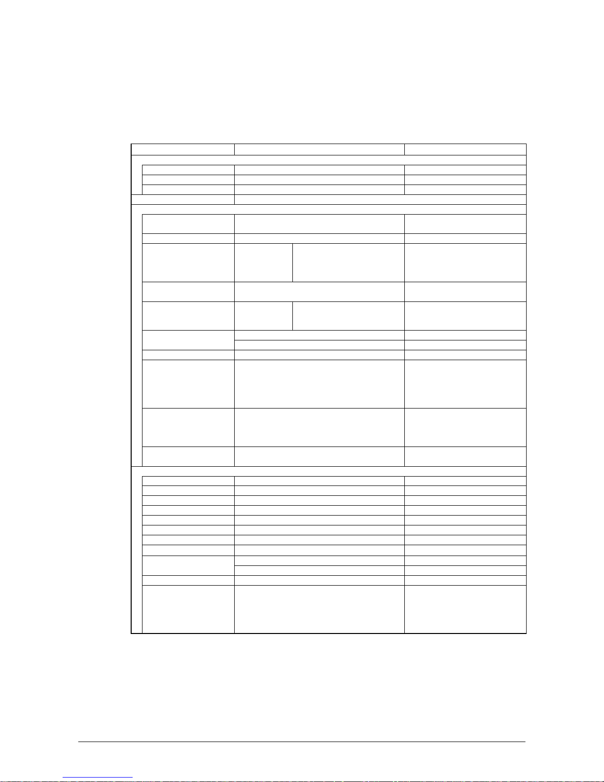
1.1 Hardware Specifications
Table 1.1
Item Specification Remark
CPU, Memory
CPU Marvell® PXA255 Application Processor Operating clock; max 400 MHz
RAM 64 MB
FROM 128 MB (user area; approx. 115 MB) FlashFX built in.
OS Microsoft® Windows® CE 5.0 operating system
C-MOS Imager (applicable to DT-X11M30E, DT-X11M30U and DT-X11M30RC)
Method C-MOS Imager, 752 x 480 (Wide VGA),
monochrome
Emitting window Redirected downward at 45 degree
Resolution 1-D:
2-D Stacked:
2-D Matrix:
Composite:
0.15mm
0.169mm
0.33mm
0.33mm
PCS 1-D:0.45 (minimum)
2-D:0.45 (minimum)
Print contrast signal
Readable distance
(Resolution = 1.0 mm)
1-D:
2-D Stacked:
2-D Matrix:
Approx. 40 to 410 mm
Approx. 50 to 250 mm
Approx. 60 to 130 mm
Max. 29 mm When the distance is at 40 mm. Readable width
Max. 265 mm When the distance is at 365 mm.
Focal distance 4.5 inches
Readable 1D
symbologies
EAN8/JAN8, EAN13/JAN12, UPC-A, UPC-E,
Code39, Codabar(NW7), Interleaved 2of5(ITF),
Code93, Code128(EAN128), MSI(Plessey),
IATA, Code11, RSS-14, RSS Limited, RSS
Expanded, ISBT
Readable 2D Stacked
symbologies
Code49, PDF417, Micro PDF, Codablock F,
EAN8/13 Composite, TLC39, UCC/EAN128
Composite, RSS-14(Stacked type), RSS
Expanded(Stacked type), RSS Composite
Readable 2D Matrix
symbologies
Aztec, DataMatrix, Maxicode, QR Code
Laser Scanner (applicable to DT-X11M10E and DT-X11M10RC)
Method Semi-conductor laser light
Emitting window Direct
Wave Length 650±10 nm
Optical Output <1 mW
No. of scannings 100±20 times per second
Resolution 0.127 mm (minimum)
PCS 0.45 (minimum) Print contrast signal
Readable distance Approximately 40 to 300 mm
Max. 40 mm When the distance is at 40 mm. Readable width
Max. 238 mm When the distance is at 300 mm.
Daylight for scanning 50,000 Lux or less
Readable 1D bar code
symbologies
EAN8/JAN8, EAN13/JAN13, UPCA, UPCE,
Code39, Codabar(NW7), Interleaved 2of5(ITF),
Code93, Code128(EAN128), MSI(Plessey),
IATA, Industrial 2of5(IDF), RSS-14, RSS
Limited, RSS Expanded
Continue.
Page 7
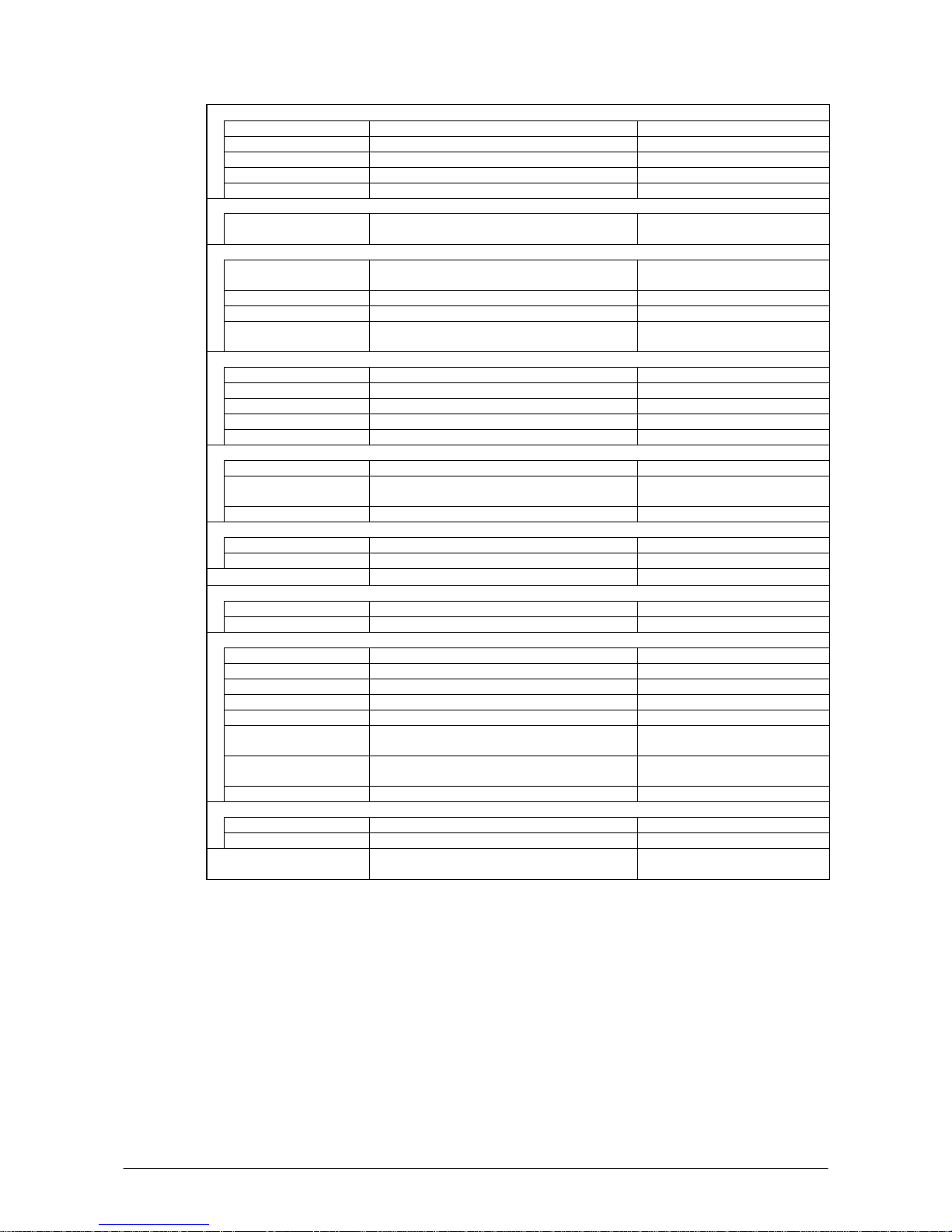
7
Display
Display device 3.5-inch 2-Way TFT color LCD See note 5.
No. of dots 240 (h) x 320 (w)
Dot pitch 0.22 (h) x 0.22 (w) mm
Display font Scalable font See note 1.
Backlight LED
Indicator
Confirmation /Status LED x 2 pcs in red/green Left: Programmable
Right: Battery charge status
Input
Keyboard Numeric (Alphabet) keys, CLR key, Execute key,
Fn key, Text key, Cursor key
Control keys Power ON/OFF key, Reset switch
Trigger keys 2 keys (on the left and right sides)
Touch panel Plastic panel (Resolution 240 x 320)
Possible to display character input pad
IrDA interface
Standard IrDA ver.1.1 compatible
Communication process Half duplex
Synchronization Start/Stop bits
Baud rate (in bps) 9,600/115,200/4M
Comm. range 0 (contact) to 1m Max 0.25m at 4Mbps
Bluetooth®
Standard Bluetooth® Specification Ver.1.2
Communication range Approx. 3 m Depending on the surrounding
conditions.
Output power Maximum. 3dBm ( PowerClass 2)
Serial interface
Standard USB Slave Mini B 5 Pin.
Baud rate Full speed (12 Mbps)
Audio
Earphone jackφ2.5mm 3-pole
Supports headset.
PC Card (applicable to DT-X11M10E, DT-X11M30E, and DT-X11M30U)
Standard PC Card Type I / Type II 3.3V
Supply current 450 mA(5V), 500 mA(3.3V) Constant supply current values
WLAN (applicable to DT-X11M10RC and DT-X11M30RC)
Frequency category 2.4 GHz ISM bandwidth
Standard IEEE802.11b See note 2.
Modulation Direct Sequence Spread Spectrum
Frequency range 2.400 to 2.4835 GHz
Baud rate 11 Mbps (maximum)
Communication range 50 m (indoor) to 150 m (outdoor) The range may vary depending on
the environment.
Number of channels 13 3 channels are available at the
same time.
Other feature Roaming between Access-Points
CF Card (applicable to DT-X11M10E, DT-X11M30E, and DT-X11M30U)
Card type CF card Types I/II (3.3V) CF Card Extension Unit (option)
Supply current 300 mA (3.3V) maximum
Security PEAP MS-CHAP-V2, PEAP EAR-TLS,
MD5+WEP128
Continue.
Page 8
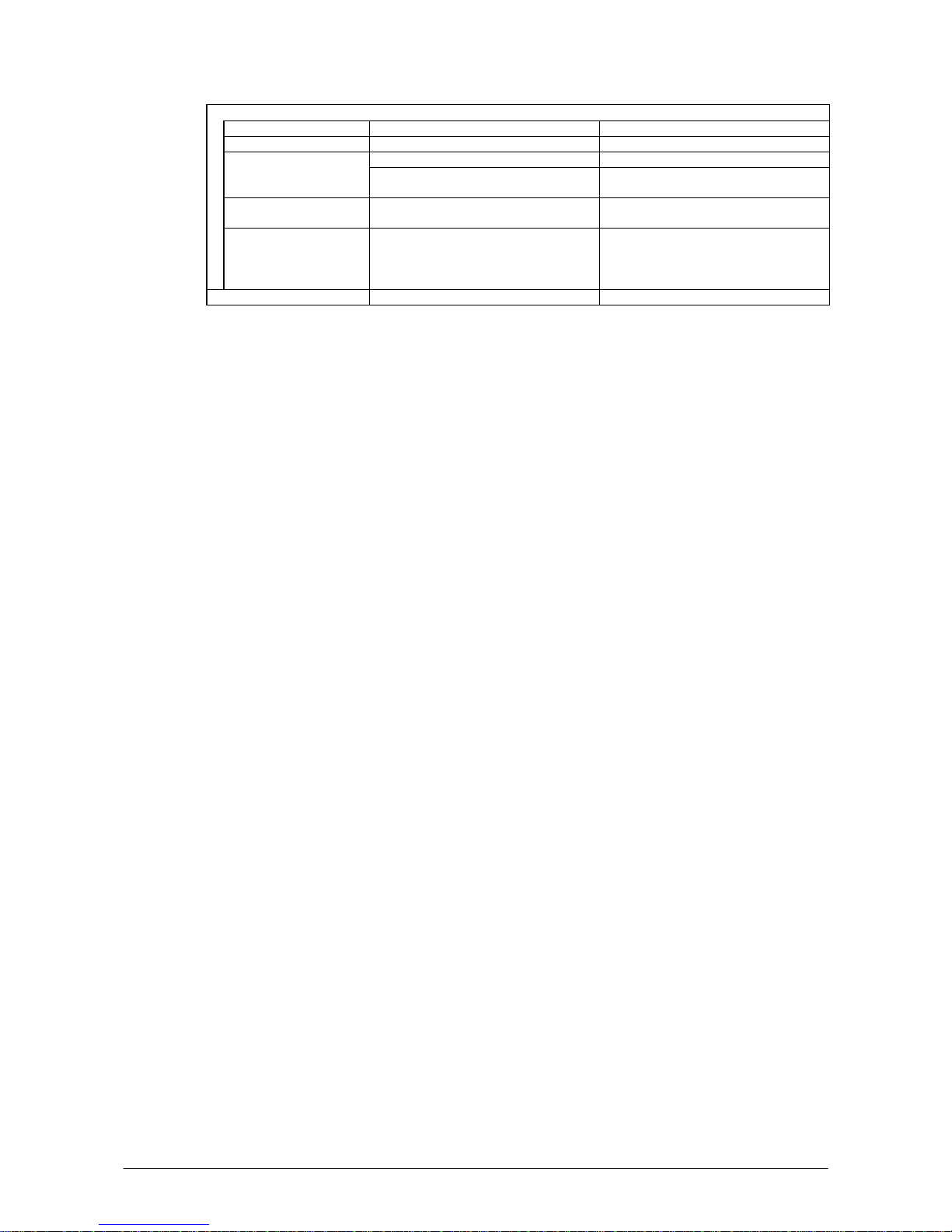
8
Power
Operation Lithium-ion battery pack HA-A20BAT or DT-5025LBAT
Memory backup Lithium battery (rechargeable) on board Built-in, not replaceable 50mAH
DT-X11M10E/M30E/M30U DT-X11M10RC/30RC Operating period (in
hours)
Approx. 8 (with HA-A20BAT)*3
Approx. 18 (with DT-5025LBAT)
*3
Approx. 4 (with HA-A20BAT)
*4
Approx. 10 (with DT-5025LBAT)
*4
Memory back up period RAM : Approx. 10 minutes,
Clock : Approx. 2 weeks
- Lithium battery pack is fully charged.
- At room temperature.
Memory backup battery
charge period
Approximately 4 days - Time period until when the battery is
fully charged.
- Battery pack is being installed.
- At room temperature.
Buzzer Sound pressure 70dB (minimum)
Notes:
1. A font that can be used to print characters of any size.
2. Concurrent use of WLAN communication with Bluetooth communication is not recommended.
3. Based on the operating cyclic ratio of “standby:calculation:scan” at 20:1:1
4. Based on the operating cyclic ratio of “standby:scan:wireless” at 6.5:1.5:2.
5. Dead Pixels
The LCD panel employed in this product uses high precision and substantial number of
components which commonly cause a small number of the pixels not to light or to remain lit all
the time. This is due to the characteristics of LCD panel yield in accuracy over 99.99% and
permissible.
Page 9
9
1.2 Library Configuration
The CASIO Software Development Kit (“SDK”) for DT-X11 series provides various libraries listed
in the table.
Table 1.2
Library Description C++
VB
C#
System Library Library that is used to control the system. Yes Yes
Laser Scanner L ibrary Library that is used to control the built-in laser scan engine. Yes Yes
Bluetooth Library Library that is used to control the built-in Bluetooth module. Yes Yes
Imager Library Library that is used to control the built-in CMOS Imager. Yes Yes
JPEG Library Library that is used to handle and manipulate JPEG image
functions.
Yes -
FLINK Library Library that is used to control and carry out transmission/reception
of files between PC and other device.
Yes Yes
Note:
The abbreviations used in the table are;
C++ : Visual C++
VB : Visual Basic .NET
C# : Visual C# .NET
The names of the Dynamic Link Libraries for C++ and C#/VB for the device oriented libraries are
listed in the table.
Table 1.3
Library Dynamic Link Library
Dynamic Link Library
(Class Library)
System Library SystemLib.dll SystemLibNet.dll
Laser Scanner Lib rary OBReadLib.dll OBReadLibNet.dll
Bluetooth Library BluetoothLib.dll BluetoothLibNet.dll
Imager Library ImagerLib.dll ImagerLibNet.dll
JPEG Library JpegCe.dll None
FLINK Library FlinkLib.dll MoFlinkLib.dll
Page 10

10
1.3 Development Reference Manuals
Besides the various library manuals listed in Table 1.1, the CASIO Software Development Kit
(“SDK”) for DT-X11 series provides also the development reference manuals listed in the table.
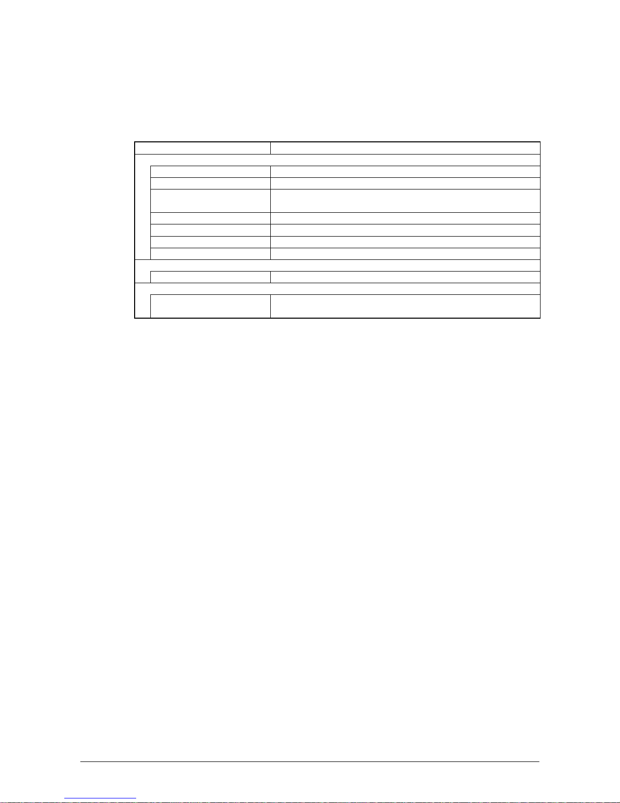
Table 1.4
Development Manual Description
Quick Start Guide This reference manual.
Hardware Manual Reference manual that describes hardware specifications in detail for each
dedicated option and DT-X11 series handheld terminal.
Software Manual Reference manual that describes software specifications in detail for all the
software integrated in DT-X11 series handheld terminal.
System Library Manual Reference manual that describes individual functions in detail for System Library.
Laser Scanner Library
Manual
Reference manual that describes individual functions in detail for Laser Scanner
Library.
Bluetooth Library
Manual
Reference manual that describes individual functions in detail for Bluetooth
Library.
Imager Library Manual Reference manual that describes individual functions in detail for Imager Library.
JPEG Library Manual Reference manual that describes individual functions in detail for JPEG Library.
FLINK Library Manual Reference manual that describes individual functions in detail for FLINK Library.
Page 11
11
1.4 Sample Program
The following sample programs are included in the CASIO Software Development Kit (“SDK”).
Table 1.5
Sample Program Description
Common Device Control Library
BLUETOOTHLIBSAMPLE Connects the terminal to a Bluetooth printer and prints out data.
CAMERALIBSAMPLE Takes pictures and displays them on the screen. See note.
IMGLIBSAMPLE Scans bar codes using the Imager with settings set with the configuration
file.
IMGLIBSAMPLE2 Program of IMGDemo.exe
OBRLIBSAMPLE Reads a bar code using the Laser library.
PRNLIBSAMPLE Prints out data on the built-in printer. See note.
SYSTEMLIBSAMPLE Demonstrates the LED and buzzer functions.
JPEG Library
JPEGSAMPLE Displays images in the JPEG file.
FLINK Library
FLINKLIBSAMPLE Demonstrate infrared communication via FLINK protocol between
terminals.
Note:
Some of the sample programs such as CAMERALIBSAMPLE and PRNLIBSAMPLE in the table
do not run because the respective devices are not integrated in the DT-X11 series handheld terminal.
Page 12

12
2. Prerequisites
2.1 Skills Required
The following skills are required by developers aiming to develop application software for the
DT-X11;
• Windows programming
• A good knowledge of one or more of the following:
- Visual C++
- Visual Basic .NET
- Visual C#
- Active Server Pages and web programming (not covered in detail in this guide)
The following skills or experiences are also desirable;
• Windows CE devices
• ActiveSync
• Some networking experience
Page 13
13
2.2 Hardware Required
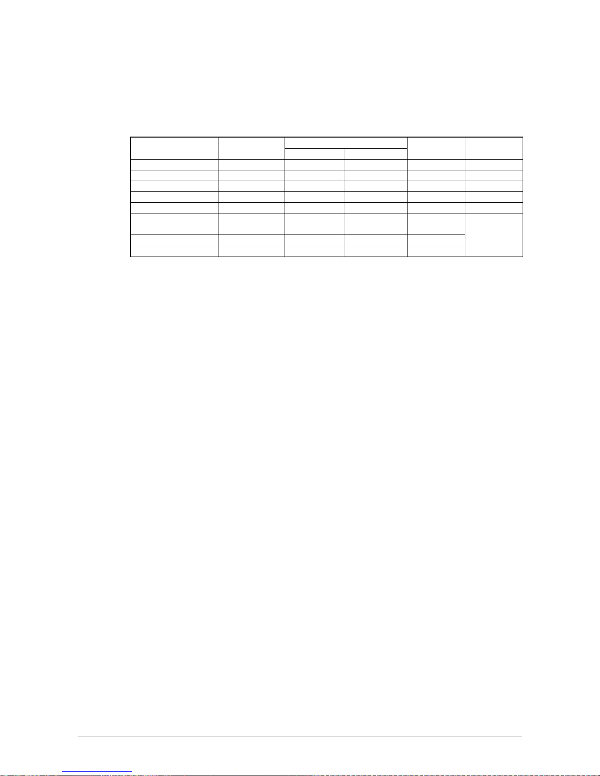
The following models of the DT-X11 series (see Table 2.1) and the dedicated options are available.
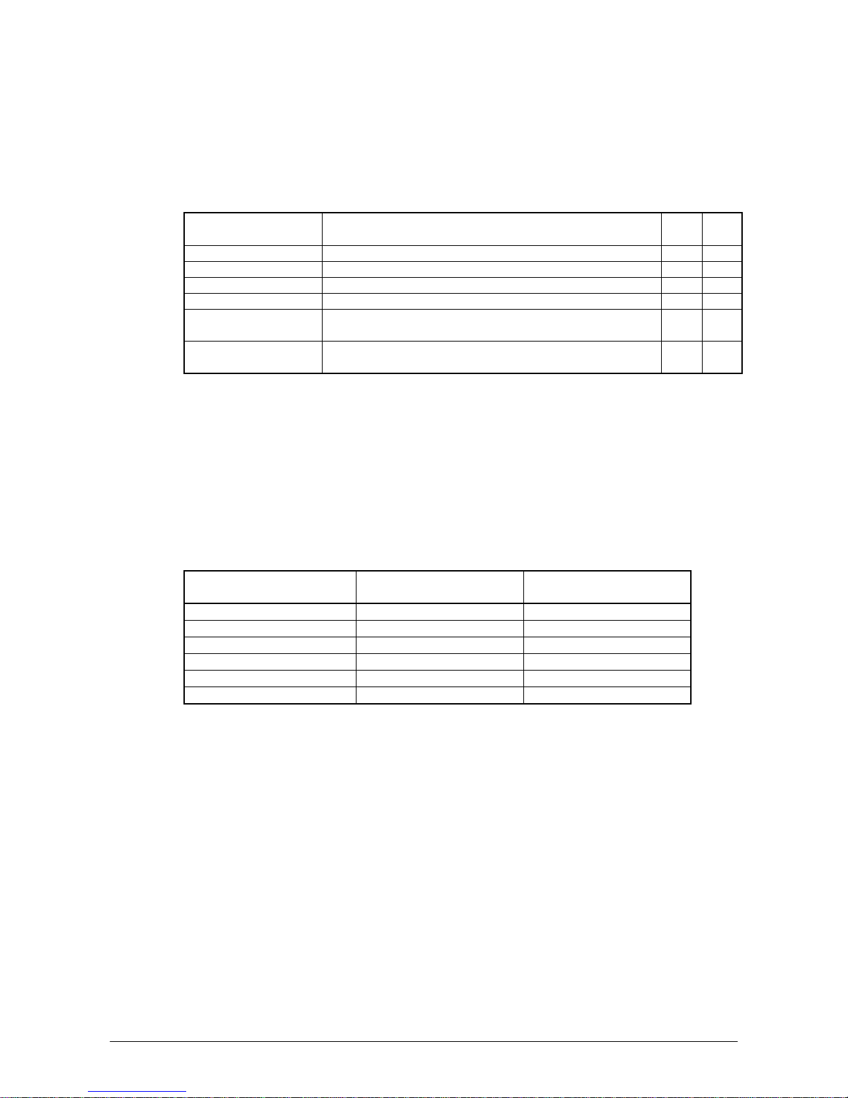
Table 2.1 Available models and features
Wireless Communication
Model No. Scan Engine
Bluetooth IEEE802.11b
PC Card
slot
Remark
DT-X11M10E Laser Scanner Yes No Yes
DT-X11M10RC Laser Scanner Yes Yes No
DT-X11M30E C-MOS Imager Yes No Yes
DT-X11M30U C-MOS Imager Yes No Yes
DT-X11M30RC C-MOS Imager Yes Yes No
DT-X11M10E-CN Laser Scanner Yes No Yes
DT-X11M10RC-CN Laser Scanner Yes Yes No
DT-X11M30E-CN C-MOS Imager Yes No Yes
DT-X11M30RC-CN C-MOS Imager Yes Yes No
See note.
Note:
“-CN” in the “Model No.” boxes denotes that the model is dedicated for China only.
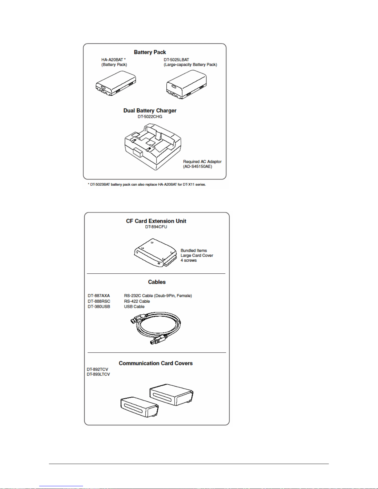
Dedicated Options
- HA-A20BAT (Battery Pack)
- DT-5025LBAT (Large-capacity Battery Pack)
- DT-160IOE (Bridge Satellite Cradle)
- DT-169CHGE (Cradle-type Battery Charger)
- DT-891WH (Wall Mount Unit)
- DT-167CHGE (Car Mounted Battery Charger)
- DT-827CAC (Car Power Cable)
- DT-5022CHG (Dual Battery Charger)
- AD-S45150AU (AC Adaptor with input capability of AC100V to 230V, and US power cord)
See note 1.
- AD-S45150AE (AC Adaptor with input capability of AC100 to 230V, and Europe power cord)
See note 1.
- AD-S60160BE (AC Adaptor with input capability of AC100V to 230V, and Europe power
cord)
- AD-S60160BU (AC Adaptor with input capability of AC100V to 230V, and US power cord)
- AD-S42120AE (AC Adaptor with input capability of AC100 to 230V) See note 2.
- AD-S42120B (AC Adaptor with input capability of AC100 to 230V)
- DT-894CFU (CF Card Extension Unit)
- DT-892TCV (Communication Card Cover)
- DT-893LTCV (Communication Card Cover, Large size)
- AC-CORD-EU (Power cord for AD-S42120B/Europe)
- AC-CORD-US (Power cord for AD-S42120B/USA and Canada)
- AC-CORD-TW (Power cord for AD-S42120B/Taiwan)
- AC-CORD-KR (Power cord for AD-S42120B/Korea)
- AC-CORD-AU (Power cord for AD-S42120B/Australia)
- DT-882RSC (RS-232C Cable)
- DT-883RSC (RS-232C Cable)
- DT-887AXA (RS-232C Cable)
- DT-888RSC (RS-422 Cable)
- DT-380USB (USB Cable)
Page 14

14
Notes:
1. The AC adaptor, AD-S45150AE (and AD-S45150AU), phased out current as of February 2008
and was replaced with the successor model, AD-S60160BE (and AD-S60160BU).
2. The AC adaptor, AD-S42120AE, phased out current as of February 2008 and was replaced with
the successor model, AD-S42120B.
See the following page for external views of the DT-X11 and its dedicated options.
Page 15
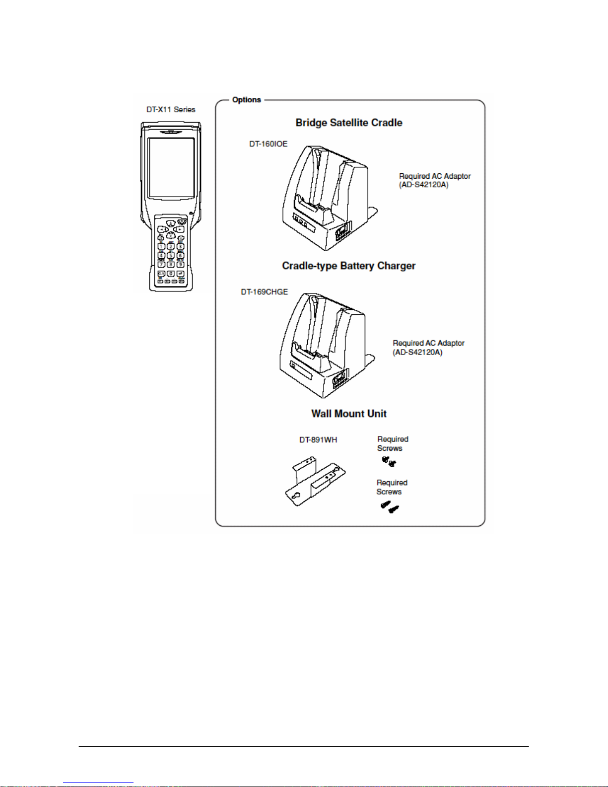
15
External views of the DT-X11 and the options
Figure 2.1
Laser Scanner models
DT-X11M10E
DT-X11M10RC
DT-X11M10E-CN
DT-X11M10RC-CN
C-MOS Imager models
DT-X11M30E
DT-X11M30U *
DT-X11M30RC
DT-X11M30E-CN
DT-X11M30RC-CN
*; The model is
available in the USA
an
d
Canada.
Page 16
16
Figure 2.2
Figure 2.3
Page 17

17
2.3 Software Required
The following software tools and libraries are required in order to develop software for the DT-X11.
Ensure that you download or purchase the correct Microsoft tools as appropriate.
C / C++
• Microsoft Visual Studio 2008 (not free of charge)
• Microsoft Visual Studio 2005 (not free of charge)
• Microsoft eMbedded Visual C++ 4.0
Download for free from;
http://www.Microsoft.com/downloads/details.asp
x?
displaylang=en&FamilyID=1DACDB3D-
50D1-41B2-A107-FA75AE960856
• Microsoft eMbedded Visual C++ 4.0 SP4
Download for free from;
http://www.microsoft.com/downloads/details.as
px?familyid=4A4ED1F4-91D3-4DBE-986E-
A812984318E5&displaylang=en
• Microsoft ActiveSync 4.2 (or later)
Download for free from;
http://www.microsoft.com/downloads/details.as
px?FamilyID=7269173a-28bf-4cac-a682-58d
3233efb4c&DisplayLang=en
• Microsoft Windows Mobile Device Center 6.1 (for Windows Vista)
Download for free from;
http://www.microsoft.com/downloads
/details.as
px?familyid=46F72DF1-E46A-4A5F-A791-0
9F07AAA1914&displaylang=en
Visual Basic / Visual C#
• Microsoft Visual Studio 2008 (not free of charge)
• Microsoft Visual Studio 2005 (not free of charge)
• Microsoft Visual Studio .NET 2003 (not free of charge)
• Windows CE Utilities for Visual Studio .NET 2003 Add-on Pack 1.1
From Microsoft web site, see
http://www.microsoft.com/downloads/details.asp
x?
familyid=7ec99ca6-2095-4086-b0cc-7c6c
39b28762&displaylang=en
• Microsoft ActiveSync 4.2 (or later)
Download for free from;
http://www.microsoft.com/downloads/details.as
px?FamilyID=7269173a-28bf-4cac-a682-58d
3233efb4c&DisplayLang=en
• Microsoft Windows Mobile Device Center 6.1 (for Windows Vista)
Download for free from;
http://www.microsoft.com/downloads/details.as
px?familyid=46F72DF1-E46A-4A5F-A791-0
9F07AAA1914&displaylang=en
Page 18

18
3. Setting Up the Development Environment
3.1 Application Development
This chapter explains about what you need to set up for the development environment before
starting your application development.
1. Installing Development Platform
Install Microsoft’s development platform which supports eMbedded Visual C++, Visual Studio
2005 and Visual Studio .NET 2003. For detail, refer to Chapter 2.3 “Software Required”.
2. Installing CASIO SDK
Instal
l CASIO’s SDK and various libraries if necessary. For installation method, refer to
Chapter 3.2 “Installing CASIO SDK Files”.
3. C
o
nnecting DT-X11 to PC (via ActiveSync or Windows Mobile Device Center)
Connect the DT-X11 to PC via Microsoft’s ActiveSync (for Windows XP or any other OS
before Windows XP) or via Windows Mobile Device Center (for Windows Vista). For
connection method, refer to Chapter 5 “Connecting the DT-X11 to PC”.
4. Setting Up th
e Development Environment
Copy
all necessary CASIO libraries to the DT-X11.
For detail, refer to Chapter 6 “Setting Up the Development Environment”.
5. Installing the
Devic
e Emulator
Install the Device Emulator for the DT-X11. For installation method, refer to Chapter 7
“Device Emulator”. If not necessary to install, go to “6. Application Development” below.
6. Application Development
Now, the
a
pplication development environment is set up and your development with the
development platform can be started. After application is developed, transfer it to the Device
Emulator or an actual terminal of the DT-X11 via ActiveSync or Windows Mobile Device
Center for check on the operability. For application development method and transferring your
application, refer to Chapters 8 “eMbedded Visual C++”, and 9 “Visual Studio”.
Page 19

19
3.2 Installing CASIO SDK Files
Download the CASIO DT-X11 SDK installation CD image file from the following site and write it
to a CD-ROM media.
http://www2.casio.co.jp/system_en/pa/PADealer/
(The site re
quires your user name and password. Enter your user name and password as issued by
CASIO.)
Notes:
• If you already installed DT-X11 SDK Ver. 1.xx in your PC, uninstall it before installing Ver.
2.xx.
• If any file of the version is remained in the following folders after uninstalling, delete it
manually.
C:\Program Files\CASIO\MBSYS
C:\Program Files\Windows CE Tools\wce500
• If your PC runs in the Window Vista, first you must disable the User Account Control (“UAC”)
by following the process below before installing the CASIO SDK Files.
- Navigate to Control Panel → User Accounts → Enable or Disable the User
Account Control. Remove the check on User Account Control (UAC) to protect your
PC, and then click OK button.
Page 20
20
Installing ExportSDK
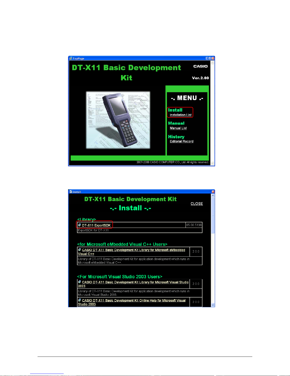
1. When the CASIO DT-X11 SDK CD-ROM is inserted into the CD-ROM drive of your PC, the
following screen appears automatically.
Figure 3.1
2. Click Installation List in Figure 3.1. The installation screen appears.
Figure 3.2
3. Click DT-X11 ExportSDK to display the Setup Wizard. Choose any one of the buttons in the
screen.
Page 21

21
Installing Library
The DT-X11 Library is available for the below development platforms.
- Microsoft eMbedded Visual C++ 4.0
- Microsoft Visual Studio .NET 2003
- Microsoft Visual Studio 2005
- Microsoft Visual Studio 2008
Notes:
1. The Library header file (*.h) and the Import library file (*.lib) are installed in the following
folder.
C:\Program Files\CASIO\MBSYS\include Header file
C:\Program Files\CASIO\MBSYS\lib\ARMV4I Import library file
2. The Class library DLL file (*.dll) is installed in the following folder.
C:\Program Files\CASIO\MBSYS\WindowsCE
3. When the Library is installed in your PC, the Help file (*.chm) is installed in the following folder.
C:\Program Files\CASIO\MBSYS\HELP
The Help file can be accessed by navigating to Start menu → All Programs → CASIO
Basic Development Kit → Help
Installing Online Help
Besides the Help file described above, the Online Help is also available for the below development
platforms. The installation of the Online Help is initiated in the Installation List for each
development platform.
- Microsoft Visual Studio .NET 2003
- Microsoft Visual Studio 2005
- Microsoft Visual Studio 2008
After the installation is complete, Microsoft Visual Studio starts up. The Online Help file can be
accessed by navigating to Help → Contents menu.
Installing Sample Program
When the Sample is chosen in the Installation List, the sample program folder in the CD-ROM
appears. The Sample program folder is available for each development platform. Copy one of the
folders you wish to use into your PC.
- EVC for Microsoft embedded Visual C++
- VS2003 for Microsoft Visual Studio.NET 2003
- VS2005 for Microsoft Visual Studio 2005
- VS2008 for Microsoft Visual Studio 2008
If your sample program is with "Read-only" attribute set effect. Be sure to disable the attribute
before using it.
Page 22
22
4. Setting Up Bridge Satellite Cradle
Use the dedicated AC adaptor (AD-S42120B) available as option for the DT-160IOE Bridge
Satellite Cradle to supply the power to the terminal. Always make sure that the power is being
supplied to the cradle by the AC adaptor before performing any kind of communication with the
terminal. The terminal draws the power via the cradle during communication.
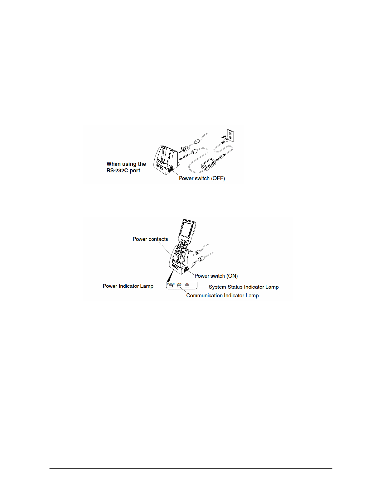
1. After making sure that the Bridge Satellite Cradle power switch is turned off, plug the AC
adaptor into the AC adaptor jack on the back of the cradle.
Figure 4.1
2. Next, plug the AC adaptor into a power outlet on wall.
Figure 4.2
3. After making sure that the Bridge Satellite Cradle and your PC are both turned off, remove the
cap from each connection port on the cradle, and then perform one of the following steps to
establish connection between the terminal and the PC. Be sure to keep the connection ports
covered whenever you are not using them.
- RS-232C Connection
Connect an RS-232C cable (DT-887AXA) to the RS-232C port on the cradle. Connect the
other end of the cable to your PC’s RS-232C port.
- USB Connection
Connect a USB cable (DT-380USB) to the USB port on the cradle. Connect the other end of
the cable to your PC’s USB port.
Page 23

23
4. Turn on the power. This causes the cradle’s power indicator lamp to light in red.
5. Making sure that their IR ports come into contact with each other, place the terminal onto the
cradle. This causes the cradle’s power indicator lamp to light in green.
• If the system is operating normally and communication is enabled, the system status
indicator lamp lights in green.
• The communication indicator lamp flashes in green when communication starts.
6. When charging is initiated, Indicator 2 (right side LED) on the DT-X11 lights up in red. When
charging has been completed, it changes its color from red to green.
Notes:
• A high-sensitivity communication element is used for IR communication. In order to ensure
successful communication, avoid using cellular phones or other devices that emit radio wave in
the area where you are performing IR communication. If you need to use such a device, move
away from the terminals that are in communication. In case of a cellular phone, keep it at least
30cm (11
16
13
") away.
• Take care to avoid allowing the cradle power contacts to become connected to each other, which
creates an electric short. Shorting the power contacts can damage the cradle.
Page 24
24
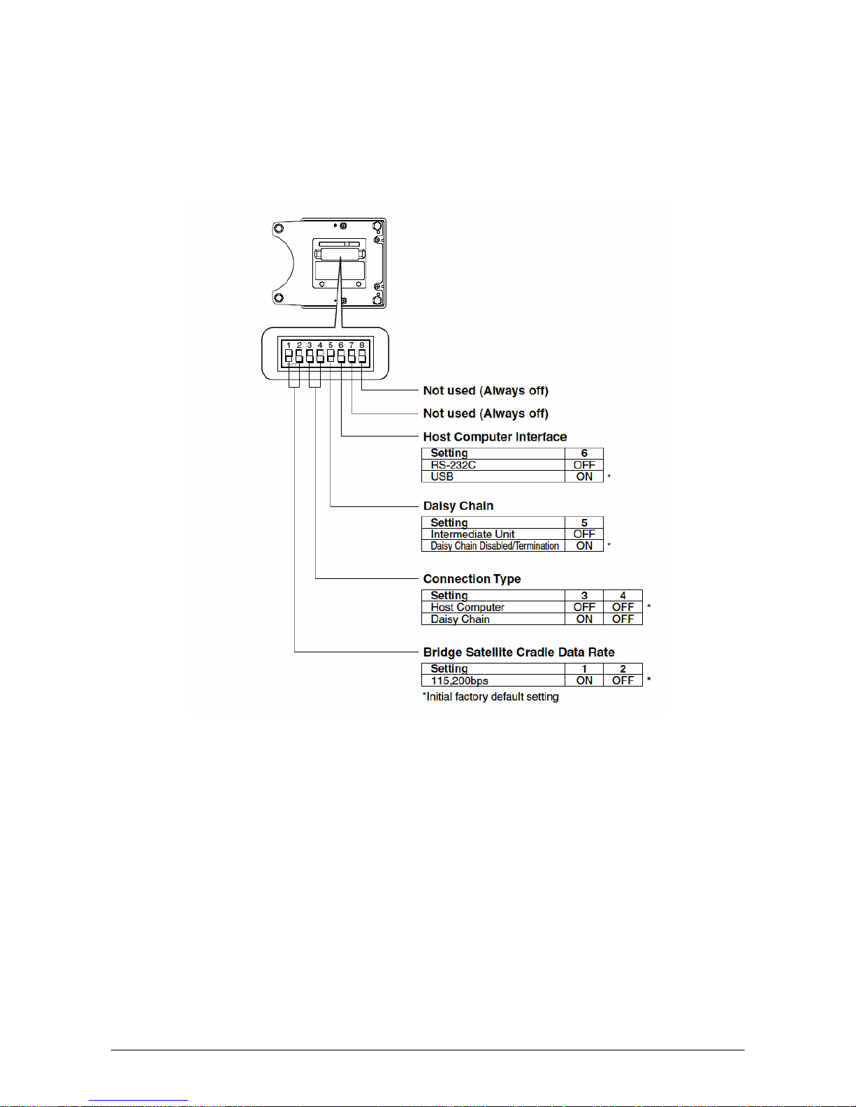
4.1 Configuring DIP Switch Settings
Dismounting the bottom cover of the Bridge Satellite Cradle exposes the DIP switches. You can
change the ON/OFF settings of the DIP switches to set the configuration. Please, set after switching
OFF the power.
Figure 4.3
Note:
Other DIP switch settings are used for testing and inspection purposes. Because of this, you should
never use any DIP switch settings other than those described above.
Page 25

25
5. Connecting the DT-X11 to PC
To make connection establishment with PC, use one of the methods, depending on the OS your PC
runs, described below.
• ActiveSync (for Windows XP or any other OS earlier)
Use the ActiveSync to connect the DT-X11 to PC if the PC runs in Windows XP or other OS
earlier than Windows XP. The ActiveSync can be downloaded at the URL below.
http://www.microsoft.com/downloads
/details.as
px?FamilyID=7269173a-28bf-4cac-a682-58d32
33efb4c&DisplayLang=en
• Windows Mobile Device Center (for Windows Vista)
Use the Windows Mobile Device Center to connect the DT-X11 to PC if the PC runs in
Windows Vista OS. The Windows Mobile Device Center (“WMDC”) can be downloaded at the
URL below.
http://www.microsoft.com/downloads
/details.as
px?familyid=46F72DF1-E46A-4A5F-A791-09F
07AAA1914&displaylang=en
Page 26

26
5.1 Connection via PCMCIA or CF Card
An effective way of getting files from PC to the DT-X11 and vice versa is to use a PCMCIA Storage
Card. Assuming you have a PC with a PC Card slot you can easily copy files to the card and transfer
them to the DT-X11. Similarly, if your PC has a Compact Flash slot you can use the DT-X11’s
PCMCIA slot with a CF card if you use a suitable CF-PCMCIA adaptor. Also, you could use the
optional DT-894CFU (“CF Card Extension Unit”) to give the DT-X11 a dedicated Compact Flash
slot.
Page 27

27
5.2 Connections via ActiveSync
In nearly all cases during development work you will be communicating with the DT-X11 via
ActiveSync connection. There are many ways to connect the DT-X11 to PC via ActiveSync.
Table 5.1
Install to your PC
Connection
ActiveSync
Direct USB
driver
IrExpress USB
driver
IrExpress
Serial driver
Direct IrDA Yes --- --- --Direct USB Yes Yes --- --Bridge Satellite Cradle via USB Yes --- Yes --Bridge Satellite Cradle via RS-232C Yes --- --- Yes
WLAN Yes --- --- --Bluetooth Yes --- --- --Ethernet PC Card Yes --- --- ---
Page 28

28
5.2.1 Via Direct IrDA
If your PC supports an IrDA port, it is possible to connect the DT-X11 to the PC via IrDA port using
ActiveSync.
Install ActiveSync to Your PC
If you have already installed ActiveSync 3.8, you may skip the steps 1 to 3 below.
1. First of all, install ActiveSync. Initiate the MSI file of ActiveSync 3.8. Then, click N
ext >
button. See Figure 5.1.
Figure 5.1
2. Click Next > button.
Figure 5.2
Page 29

29
3. Hold the installation process when the menu in Figure 5.3 appears. Go to the next procedure
Establish Connection with Your PC in the next page.
Figure 5.3
Page 30

30
Establish Connection with Your PC
1. Choose PC Connection icon in the Control Panel on the DT-X11.
2. Set PC Connection to IrDA. If it is not IrDA, tap Change Connection… button in PC
Connection tab (see Figure 5.4) and choose IrDA in the pull-down menu box in the window in
Figure 5.4. Tap OK bu
tton twice.
Figure 5.4
3. On the PC, make sure Allow s
erial cable or infrared connection to this COM port has
been set effect and Infrared Port [IR] is chosen in the pull-down menu box (see Figure 5.5).
Figure 5.
5
4. Place the IrDA port located on the bottom side of the DT-X11 facing to the IrDA port on the PC
directly. Communication can be established if the distance is within zero to one meter. The
maximum distance is 30cm when communicating at 4 Mbps.
5. From Start menu, navigate to Programs → Communication → ActiveSync and then start
up ActiveSync.
Page 31

31
Establish Partnership
1. Now go back to the procedure Install ActiveSync to Your PC in Chapter 5.2.1 “Via Direct
IrDA”. Click Next > button in Figure 5.6.
Figure 5.6
2. Now the connection is established. You can choose either one of the radio buttons (see Figure
5.7) acc
ording to your need. Then click N
ext > button.
Figure 5.7
3. Now establishing connection is completed. You can start up eMbedded VC++ and create a
program and then deploy it into the DT-X11.
Figure 5.8
Page 32

32
5.2.2 Via Direct USB
The DT-X11 has a mini USB connector on its left hand side. You can use this to directly connect the
DT-X11 to your PC using a mini USB A-B cable.
Install ActiveSync to Your PC
1. If you have already installed ActiveSync 3.8, you may skip this step. For installing
ActiveSync, refer to Install ActiveSync to Your PC in Chapter 5.2.1 "Via Direct IrDA”.
Install USB Driver to Your PC
1. Connect a mini-USB cable to the port on the DT-X11, and connect the other end of the cable to
a USB port on your PC. When the DT-X11 is connected for the first time, a dialog appears to
prompt you to install the suitable driver.
2. Download the USB driver “wceusbsh.inf” and “wceusbsh.sys” at the CASIO website and copy
them to appropriate folder in your PC.
3. Choose No, not this time and then click N
ext > button (see Figure 5.9).
Figure 5.9
4. Choose Install from a list or specific location [Advanced] and then click N
ext > button
(see Figure 5.10).
Figure 5.10
Page 33

33
5. Click N
ext > button.
Figure 5.11
6. Choose Windows CE USB Devices icon (see Figure 5.12).
Figure 5.12
7. Click H
ave Disk… button (see Figure 5.13).
Figure 5.13
Page 34

34
8. Click B
rowse… button (see Figure 5.14), and choose “wceusbsh.inf” in the folder you have
created in the step 2 of Install USB Driver to Your PC on page 32.
Figure 5.14
9. Then installing the driver will start.
Figure 5.15
10. Click C
ontinue Anyway button. A menu may prompt you to install the “wceusbsh.sys” file.
This happens if it is not in the same folder in where “wceusbsh.inf” is located. Download the
file from the CASIO website and follow instruction appeared and then specify the location of
the file.
Figure 5.16
Page 35

35
11. Now installing the driver is completed.
Figure 5.17
Page 36

36
Establish Connection with Your PC
1. Choose PC Connection icon in the Control Panel on the DT-X11.
2. Set PC Connection to USB. If it is not USB, tap Change Connection… button and choose
USB in the pull-down menu box in the window in Figure 5.18. Tap OK button twice.
Figure 5.18
3. On the PC, make sure Allow U
SB connection with this desktop computer. has been set
enabled (see Figure 5.19).
Figure 5.19
4. Fro
m Start menu, navigate to Programs → Communication → ActiveSync and then start
up ActiveSync.
Establish Partnership
For establishing the partnership, see the procedure Establish Partnership in Chapter 5.2.1 "Via
Direct IrDA” on page 31.
Page 37

37
5.2.3 Through Bridge Satellite Cradle via USB
In order to communicate through the Bridge Satellite Cradle (DT-160IOE) via USB, you will need
to install the IrXpress USB driver on your PC.
Install ActiveSync to Your PC
If you have already installed ActiveSync 3.8, you may skip this step. For detailed explanation on
installing ActiveSync, see the procedure Install ActiveSync to Your PC in Chapter 5.2.1 "Via
Di
rect IrDA” on page 31.
Install IrXpress USB Driver to Your PC
1. Initiate the IRXpressUSBIrDA.exe. Specify the folder in where the file has been saved and then
click N
ext > button.
Figure 5.20
2. Click N
ext > button.
Figure 5.21
Page 38

38
3. Choose Yes, I want to restart my computer now. radio button, and then click Finish
button. Reboot your PC to set the IrXpress driver enabled.
Figure 5.22
Connect Bridge Satellite Cradle to Your PC
1. On the base of the Bridge Satellite Cradle you will find a bank of DIP switches. Ensure that
switch no. 6 is in the ON position to enable USB connection. If you change the switch settings,
ensure that you power off and then on again so that the settings take effect.
2. Insert the client end of the USB cable into the USB port on the Bridge Satellite Cradle.
3. Insert the host end of the USB cable into a USB port on your PC.
4. The hardware will be detected and configured automatically.
Establish Connection to Your PC
For detailed explanation on establishing connection, see the procedure Establish Connection to
Your PC in Chapter 5.2.1 "Via Direct IrDA” on page 28.
Establish Partnership
For detailed explanation on establishing the partnership, see the procedure Establish Partnership
in Chapter 5.2.1 "Via Direct IrDA” on page 31.
Page 39

39
5.2.4 Through Bridge Satellite Cradle via RS-232C
In order to communicate through the Bridge Satellite Cradle (DT-160IOE) via RS-232C, you will
need to install the IrXpress Serial Driver on your PC.
Install ActiveSync to Your PC
If you have already installed ActiveSync 3.8, you may skip this step. For detailed explanation on
installing ActiveSync, see the procedure Install ActiveSync to Your PC in Chapter 5.2.1 "Via
Di
rect IrDA” on page 28.
Install IrXpress Serial Driver to Your PC
1. Initiate the IRXpressSerialIrDA.exe. Specify the folder in where the file is saved, and then click
N
ext > button.
Figure 5.23
2. Click N
ext > button.
Figure 5.24
Page 40

40
3. Choose Yes, I want to restart my computer now. radio button, and then click Finish
button (see Figure 5.25). Reboot your PC to set the IrXpress driver enabled.
Figure 5.25
Establish Connection to Your PC
1. On the base of the Bridge Satellite Cradle you will find a bank of DIP switches. Ensure that
switch no. 6 is in the OFF position to enable RS-232C connection. If you change the switch
settings, ensure that you power off and then on again so that the settings take effect.
2. Plug one end of the 9 pin RS-232C cable (DT-887AXA) into the Serial port on the Bridge
Satellite Cradle.
3. Plug the other end of the RS-232C cable (DT-887AXA) into the correct COM port on your PC.
4. In order to set which COM port the IrXpress driver uses on your PC, choose Wireless Link in the
Control Panel.
5. Click Hardware tab and choose CASIO IrXpress Serial Infrared from the Devices list. Click
Properties.
6. Click Advanced tab. You can now choose the physical COM port to which the cradle is
attached and maximum connection speed (set this to 115200 bps). Click OK button and then OK
button again. The connection is now ready to use.
Establish Partnership
For detailed explanation on establishing the partnership, see the procedure Establish Partnership
in Chapter 5.2.1 "Via Direct IrDA” on page 31.
Page 41

41
5.3 Connection via Windows Mobile Device Center
To establish connection via USB interface with PC runs in Windows Vista, use Windows Mobile
Device Center (“WMDC”). The DT-X11 with the factory-setting (default) does not support the
WMDC. Follow the procedure below to change the setting on the DT-X11.
Note that the CAB file, USBClientDTX11.110.CAB, must be installed in the DT-X11 prior to
establishing connection with the DT-X11 via Windows Mobile Device Center. For installation
method, refer to Chapter 6.1 “Installing CAB Files”.
Procedure
1. Close
al
l applications running on the DT-X11.
2. Navigate to Settings → Control Panel → USB Connection.
3. Click Connect Utility tab (see red circle).
Figure 5.26
4. Choose Windows Mobile Device Center radio button and then click OK button.
Figure 5.27
5. A dialogue asking your final confirmation appears. Click YES button.
Figure 5.28
Page 42

42
6. The DT-X11 starts up again.
7. Mount the DT-X11 on the cradle, and then follow a message appeared in the WMDC on the PC.
Notes:
• To resume the factory default setting, choose ActiveSync/LMWIN radio button in Step 4 on
the previous page, and start up the DT-X11 again.
• The WMDC version 6.1 or later will support the connection establishment via USB interface.
Any other versions of the WMDC earlier are not interoperable with Windows CE devices.
Page 43

43
5.4 Connection via WLAN
The fastest and easiest way to connect the DT-X11 to your PC for development purpose is WLAN
compliant with the IEEE802.11b standard. In this configuration, models with WLAN module
integrated (applicable to DT-X11M10RC, M30RC, M10RC-CN, and M30RC-CN) are operable.
Follow the steps below to establish connection between the DT-X11 and PC via WLAN.
Establish Partnership
Establish partnership first between the DT-X11 and PC via Direct IrDA or Direct USB, or via
Bridge Satellite Cradle.
Set up WLAN Connection on the DT-X11
1. Initiate NetSearch tool by navigating to Programs → Communication → NetSearch.
Figure 5.29 displays a list of WLAN stations.
Figure 5.29
2. Navigate to Display → New Connection menu and set up the parameters shown in Basic
(see Figure 5.30), IP Setting (see Figure 5.31), and WLAN Setting (see Figure 5.32) tabs.
3. Enter the
SSID (see Figure 5.30) and other necessary security param
eters for the network. Tap
OK button and then close the configuration window.
4. A prompt that informs you that a reset is necessary to confirm these changes. Tap OK button.
Figure 5.30 Figure 5.31 Figure 5.32
Page 44

44
Establish Connection to Your PC
1. On the PC, make sure Allow network [Ethernet] and Remote Access Service [RAS]
server connection with this desktop computer. has been set enabled (see Figure 5.33).
Figure 5.33
2. On the DT-X11, navigate to Start → Programs → Communication → LAN ActiveSync
to initiate the connection.
3. Ensure that Network Connection is the name of the connection method and that Connect to
line is the name of your PC.
4. Tap Connect … button and then the connection should be established.
Page 45

45
5.5 Connection via Bluetooth
There are many peripherals such as USB dongles and PC Cards on the market that will allow you to
add a Bluetooth serial port to a PC. This guide only covers the DT-X11 side of the connection and
assumes that you have a suitably configured Bluetooth COM port available on your PC. Your PC
may require a Passkey during connection; if so, you will be prompted on the DT-X11 at some point
to enter the Passkey before the connection can be completed.
Establish Partnership
Establish partnership first between the DT-X11 and PC via Direct IrDA or Direct USB, or via
Bridge Satellite Cradle.
Set up Bluetooth Connection on the DT-X11
1. On the DT-X11, navigate to Start → Settings → Control Panel → Bluetooth
Connection.
2. After a few seconds, a list of detected Bluetooth devices should appear. Identify the PC amongst
these and double tap its icon in the list.
3. A list of available services for the PC will appear. Bluetooth Serial Port should be among
them (the exact name may vary depending on the Bluetooth hardware you are using on the PC).
4. Tap and hold Bluetooth Serial Port icon (see Figure 5.34) and a pop-up menu should appear
with a
n
icon Use to connect for ActiveSync.
5. Tap this icon, and then it will change to an ActiveSync icon.
Figure 5.34
6. Tap Bluetooth Serial Port (or whatever the specific item is on your PC) and then ActiveSync
connection to the PC will be established.
7. If you tap and hold Bluetooth Serial Port icon in the screen that displays the PC side services,
you can choose Add Shortcut menu to create a shortcut to this connection.
8. Tap the blue icon in the Taskbar (see Figure 5.34) and choose Shortc
ut.
9. Tap a
nd hold the shortcut you created in the step 5 and tap Auto Connection in the context
menu (see Figure 5.35).
Page 46

46
10. The ActiveSync connection will then be launched as soon as you start the Bluetooth connection
utility.
Figure 5.35
11. To disconnect the ActiveSync session it is best to double tap the connection icon in the Taskbar
and tap Disconnect button.
Page 47

47
5.6 Connection via Ethernet PC Card
This procedure has been tested using a SOCKET LP-E (CF card) in a CF to PCMCIA converter.
Establish Partnership.
Establish partnership first between the DT-X11 and PC via either Direct IrDA or Direct USB, or via
Bridge Satellite Cradle.
Set up Ethernet Connection on the DT-X11
1. Insert the LAN card into the PC Card slot on the DT-X11.
2. On the DT-X11, navigate to Start → Settings → Control Panel → Network and Dialup
Connections.
3. You should see NE20001 as an option. Highlight this and choose Properties from the
Connection menu.
4. Configure the settings suitably for your network.
5. On the Name Servers tab, you should enter the IP address of your PC on the Primary WINS
line.
Establish Connection to your PC
1. On the PC, make sure Allow network [Ethernet] and Remote Access Service [RAS]
server connection with this desktop computer. has been set enabled (see Figure 5.36).
Figure 5.36
2. O
n the DT-X11, navigate to Start → Programs → Communication → LAN ActiveSync
to initiate the connection.
3. Ensure that Network Connection is the name of the connection method and that Connect to
line is the name of your PC.
4. Tap Connect … button and then the connection should be made.
Page 48

48
5.7 Accessing Shared Network Drive via WLAN
Assuming you have a valid network connection established, you can access shared drives on your
PC from the File Explorer on the DT-X11. The following shows the steps to initiate.
1. Configure a network connection on the DT-X11.
2. Double tap My Computer.
3. Type \\xxxx\ where xxxx is the network name of the PC.
4. A network logon dialog box will appear. Enter a valid User ID, Password and Network Domain.
5. Any shared network drives on the target PC will be displayed and you will be able to copy files
freely between them and the DT-X11.
Page 49

49
5.8 Connection via Direct TCP/IP from Visual Studio
Visual Studio .NET 2003
If you have a network connection from the DT-X11 (for example, via WLAN) then you can use the
Windows CE Utilities add-on pack (described in Chapter 3) to establish a direct link to the
deve
lopment PC. Refer to the readme file supplied with the add-on pack for details.
Visual Studio 2005
Visual Studio 2005 does not support remote debugging via the direct TCP/IP connection.
Page 50

50
6. Setting Up the Development Environment
6.1 Installing CAB Files
1. After installing the library files, the CAB files in Table 6.1 will be installed in the folder below.
C:\Program Files\CASIO\MBSYS\CAB
Table 6.1
Library CAB file Preinstalled
System Library en_SystemLib.ARMV4I.CAB Yes
Laser Scanner Library en_OBReadLib.ARMV4I.CAB Yes
Bluetooth Library en_BluetoothLib.ARMV4I.CAB Yes
Imager Library en_ImagerLib.ARMV4I.CAB Yes
JPEG library en_JPEG.ARMV4I.CAB Yes
FLINK library en_Flink.ARMV4I.CAB Yes (note 2)
Notes:
1. The library with "Yes" in "Preinstalled" column is preinstalled in the DT-X11 and in the
Device Emulator. Thus, it is not necessary to install it, unless it has been updated or changed.
2. The CAB file, en_Flink.ARMV4I.CAB, in the table does not operate for the DT-X11. Use the
FlinkLib.dll installed by default in the terminal.
2. Download the CAB file in Table 6.2 from the following site.
http://www2.casio.co.jp/system_en/pa/PADealer/
(The site requires your user name and password. Enter your user name and password as issued by
CASIO.)
Table 6.2
CAB file Description
USBClientDTX11.110.CAB USB client supported by Windows Mobile Device Center
3. Copy all the CAB files in Tables 6.1 and 6.2 to any folder on the DT-X11 via ActiveSync.
4. Carry out each CAB file.
5. When the installation starts, the installation status will appear.
Page 51

51
6.2 eMbedded Visual C++ 4.0
ExportSDK for DT-X11 is required to develop application software with eMbedded Visual C++
4.0 (see note 1). Follow the steps below to install it.
1. Double click DT-X11_SDK.msi (see note 2) file and follow the prompts appeared on the screen
to install the SDK.
2. When prompted whether you want to install Custom or Complete installation, choose
Complete.
3. When the installation is finished, start up eMbedded Visual C++ 4.0.
4. Go to Chapter 8 and follow the instructions to verify that the SDK has been installed correctly.
If eMbe
dded C++ has been installed in your PC already, you will notice that you now have a new
SDK and, once you select that new SDK, a new target device (DT-X11) in the comb-box menu in
the Toolbar. Also, if you use any of the Remote Tools in eVC++ then you will find DT-X11 is listed
as a new target (for example, try the Remote Registry Editor).
Notes:
1. If eMbedded Visual C++ 4.0 is used to develop application software, be sure to install Service
Pack 4 prior to the development.
2. Other SDK (e.g. standard SDK etc.) released before ExportSDK for DT-X11 is also operable.
3. If DT-X11_SDK is installed when standard SDK has been installed already, the following
dialog box in Figure 6.1 appears for warning.
Figure 6.1
4. Application software developed using MFC (Microsoft Foundation Class) for CASIO IT-10 is
not operable on the DT-X11.
5. Any application developed not using MFC is operable on the DT-X11.
Page 52

52
6.3 Visual Studio 2005
There is no actual SDK available for Visual Studio as such. However, the CASIO libraries have
been released for VB .NET and C#. See Chapter 9 for basic usage instructions. In this chapter, the
remote debugging procedure using the DT-X11 for application development in VB .NET and C#
environments is explained.
1. Establish connection with the DT-X11 via ActiveSync.
2. Open the application project for VB .NET or C# in Visual Studio 2005.
3. Click the button in square box drawn by red line (see Figure 6.2) to make sure that Visual Studio
20
05
has recognized the connection established with the DT-X11 via ActiveSync. If it does not,
start up ActiveSync again to establish connection.
Figure 6.2
4. Choose DT-X11 Device in the pull-down menu box in Figure 6.3.
Figure 6.3
5. If the debugger has started, debugging for the application can be carried out while checking each
operation by the application running on the DT-X11.
Page 53

53
6.4 Visual Studio .NET 2003
There is no actual SDK available for Visual Studio as such. However, the CASIO libraries have
been released for VB .NET and C#. See Chapter 9 for basic usage instructions. Microsoft has
released an add-on for Visual Studio .NET 2003 that allows you to set the target CPU for a
connected device (Visual Studio is unable to detect the target CPU of non-Pocket PC devices).
Follow the steps below to install the add-on pack.
1. Download “Windows CE Utilities for Visual Studio .NET 2003 Add-on Pack 1.1” from the site
described in Chapter 2.3 “Software Required”.
2. Estab
lish
connection via ActiveSync between the DT-X11 and PC using any of the methods
described in Chapter 5 “Connecting the DT-X11 to PC”.
3. Navigate
to Tools → Select Windows CE Device CPU.
4. In Select the device architecture pull-down menu box, choose ARMV4I.
5. Click Configure.
6. Re-start Visual Studio .NET 2003.
You will now, for example, be able to choose Deploy <appname> from the Build menu and your
project will be deployed directly to the DT-X11. You will now also be able to remotely debug
applications over your ActiveSync connection.
Page 54

54
7. Device Emulator
The Device Emulator provides application developers with an environment that, without having
the actual device available, allows them to debug basic functions and performance of an application
at source level by stepping through the code.
7.1 Software Required
The Device Emulator requires the software(s) listed below before installing the emulator.
Using Visual Studio 2008 or Visual Studio 2005
• ActiveSync 4.2 or a later version (If required)
http://www.microsoft.com/downloads/details.as
px?FamilyID=7269173a-28bf-4cac-a682-58d323
3efb4c&DisplayLang=en
• Visual Studio 2008 or Visual Studio 2005 (Required)
• CASIO DT-X11 SDK (Required)
• Standalone Device Emulator 3.0 (Optional. See note 2.)
http://www.microsoft.com/downloads/details.aspx?
displaylang=en&FamilyID=a6f6adaf-12e3-
4b2f-a394-356e2c2fb114
Using Visual Studio .NET 2003
• ActiveSync 4.2 or a later version (If required)
http://www.microsoft.com/downloads/details.aspx?FamilyID=7269173a-28bf-4cac-a682-58d32
33efb4c&DisplayLang=en
• Standalone Device Emulator 3.0 (If required. See notes 1 and 2.)
http://www.microsoft.com/downloads/details.aspx?
displaylang=en&FamilyID=a6f6adaf-12e3-4
b2f-a394-356e2c2fb114
• Visual Studio .NET 2003 (Required)
• CASIO DT-X11 SDK (Required)
Using eMbedded Visual C++ 4.0
• ActiveSync 4.2 or a later version (Required)
http://www.microsoft.com/downloads/details.as
px?FamilyID=7269173a-28bf-4cac-a682-58d32
33efb4c&DisplayLang=en
• Standalone Device Emulator 3.0 (If required. See notes 1 and 2.)
http://www.microsoft.com/downloads/details.aspx?
displaylang=en&FamilyID=a6f6adaf-12e3-4
b2f-a394-356e2c2fb114
• Microsoft eMbedded Visual C++ 4.0 (Required)
http://www.Microsoft.com/downloads/details.aspx?
displaylang=en&FamilyID=1DACDB3D-50
D1-41B2-A107-FA75AE960856
• Microsoft eMbedded Visual C++ 4.0 ServicePack4 (Required)
http://www.microsoft.com/downloads/details.as
px?familyid=4A4ED1F4-91D3-4DBE-986E-A8
12984318E5&displaylang=en
• CASIO DT-X11 SDK (Required)
Page 55

55
Notes:
1. The software is not required if your PC already has Visual Studio 2005 installed.
2. To use Microsoft Device Emulator 3.0, follow the steps below.
2-1. Install DT-X11 ExportSDK and Device Emulator of the DT-X11 SDK.
2-2. Download Microsoft Device Emulator 3.0 and install it.
2-3. Edit the following file and save the change.
C:\Program Files\Windows CE Tools\wce500\DT-X11\Emulation\DT-X11.cdes
Before you change, the default parameter in the file is described as follows.
module=DevEmu500.exe
Change the parameter to the one below. Be sure to describe the whole parameter in single one
line.
module=C:\Program Files\Microsoft Device Emulator\1.0\
DeviceEmulator.exe
You can substitute the Device Emulator Version 3.0 released in Visual Studio 2008 for an engine of
Device Emulator included in the DT-X11 SDK by the mentioned procedure above.
Page 56

56
7.2 Starting Up the Device Emulator
After installing all required software described in Chapter 7.1, follow the steps below to start up the
Device Emulator on your PC.
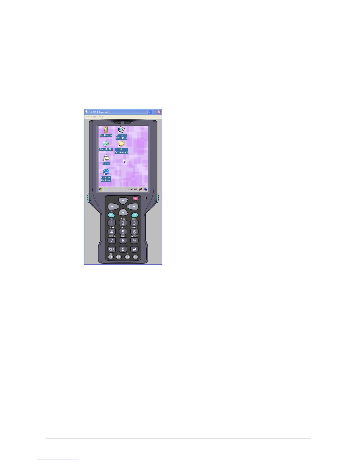
1. Navigate to Start menu → All Programs → CASIO Device Emulator and click DT-X11.
Make sure that the DT-X11 Device Emulator has started up on the screen. See Figure 7.1. If
Figure 7.1 and Figure 7.2 appear on your PC, you are ready to use the emulator.
Figure 7.1 DT-X11 Device Emulator Figure 7.2 I/O Simulator
Terminology of Emulator and Simulator;
The Emulator described in this reference manual is a software application that behaves in a very
similar way to the actual device by imitating individual hardware components or protocols present in
the actual hardware.
On the other hand, the Simulator is also a software application that logically integrates application
programming interfaces (“API”) and certain other functions to allow debugging of the application
program using external events. The Emulator performs in a pseudo CPU and hardware
environment and it is impossible for the application to recognize whether it is in the actual device
environment or pseudo environment. However, actions carried out by the Simulator are not as
alike to those performed by actual components but merely mimic them very closely.
Page 57
57
7.3 Using the Device Emulator
7.3.1 DT-X11 Device Emulator
The DT-X11 Device Emulator emulates various operations carried out by the actual DT-X11
terminal on the PC’s screen such as mouse operation, input on PC’s keyboard, displaying execution
of applications, and operations by actual devices such as the scanner. Figure 7.3 shows an emulated
DT
-X11 device on the screen of a PC.
Figure 7.3
Key Input
The emulator offers key input capability similar to that of the actual DT-X11 device. For instance, a
key on the emulated keyboard of DT-X11 on the screen (see Figure 7.3) can be clicked with the PC
mouse as well as key input made directly on the PC’s keyboard.
Reading Bar Codes
The emulator enables bar codes pre-registered in the I/O Simulator (see Figure 7.2) to be input when
clicking Trigger key on the emulated keyboard (see Figure 7.3). Note however that the Trigger key
mu
st be continuously pressed for a second or more otherwise an incorrect key input may result.
Sound
The emulator offers beep and sound capability similar to that of the actual DT-X11 device.
Page 58

58
7.3.2 I/O Simulator
The I/O Simulator simulates registration of bar codes, generation of low battery warning, detection
of terminal being mounted on cradle.
Registration of bar code symbologies
1. Registration
Click either ADD1D or ADD2D button (circled in red in Figure 7.4) to go into the bar code
registratio
n mode.
Figure 7.4
2. Bar code registration
Choose a bar code symbology in the Code Type pull-down menu that you wish to register in the
I/O Simulator.
Figure 7.5
Page 59

59
3. Registration of bar code and note
Enter bar code data in the Barcode field (see Figure 7.6) and a note about the bar code in the
Note field if necess
ary. Click OK button to complete the bar code registration.
Figure 7.6
4. Completion of registration
After completion of the bar codes registration, the screen in Figure 7.7 shows a list of bar codes
that
have been registered in the I/O Simulator. Prior to debugging with the Device Emulator,
make sure that you register all bar codes you wish to use in debugging.
Figure 7.7
Page 60

60
5. Editing registered bar code content
Highlight a bar code in the list of registered bar codes (see Figure 7.7) and click Edit butto
n.
Figure 7.8 appears for editing the bar code and its information.
Figure 7.8
6. Deleting registered bar code content
Highlight a bar code in the list of registered bar codes (see Figure 7.7) and click Del butto
n.
Dialogue screen in Figure 7.9 appears for you to confirm the deletion. If it is okay to delete, click
Yes button, otherwise click No button.
Figure 7.9
Page 61

61
Detecting Terminal in Cradle and Low Battery Warning
If you check the I/O Box and Low Battery boxes in STATE SETTING field (see Figure 7.10), the
simulator simulates the respective events in the emulator.
Figure 7.10
I/O Box
If this box is checked, a notification is issued that the connection between the DT-X11 Device
Emulator and cradle has been established. This notification can be utilized by the application.
Low Battery
If this box is checked, a notification that a low battery state has occurred is raised. The icon in the
toolbar in the emulated screen appears too. The notification can be utilized by the application to
recognize the low battery state in the hardware.
Page 62

62
Indications
The I/O Simulator expresses a change of state that occurred in the DT-X11 Device Emulator.
• LED
When the DT-X11 Device Emulator turns on the LED, the LED icon (LED2) in the I/O Simulator also turns
on. See Figure 7.11.
• Vibration
When the DT-X11 Device Emulator vibrates, the vibration icon in the I/O Simulator also turns on. See Figure
7.11.
Figure 7.11
Page 63

63
7.3.3 Connecting via ActiveSync
If debugging with the Device Emulator is carried out in either eMbedded Visual C++ 4.0 or
Visual Studio 2008 or Visual Studio 2005, or transmission/reception of a file with the Device
Emulator is carried out, ActiveSync must be used.
Setting ActiveSync
1. Start up ActiveSync and then navigate to File → Connection Settings ….
Figure 7.12
2. In Connection Settings screen, check in the Allow con
nections to one of the following
box and choose DMA in the pull-down menu. See Figure 7.13.
Figure 7.13
Page 64

64
Connection via ActiveSync
The ways to establish connection of the Device Emulator via ActiveSync are;
• Using Visual Studio 2008 or Visual Studio 2005
• Using Standalone Device Emulator 3.0 (if Visual Studio 2008 or Visual Studio 2005 is not
available.)
1. Start up the Device Emulator by referring to Chapter 7.2 “Starting Up the Device Emulator”.
2. Start up
Visual Studio 2008 or Visual Studio 2005, and then navigate to Tools → Device
Emulator Manager.
If Visual Studio 2008 or Visual Studio 2005 is not available, use the Standalone Device Emulator
3.0.
C:\Program Files\Microsoft Device Emulator\1.0\dvcemumanager.exe
3. Right-click DT-X11 Emulator in Available Emulators list and then choose Cradle in the
popup menu. See Figure 7.14.
Figure 7.14
Page 65

65
4. Make sure ActiveSync has started up and the icon in the status bar appears in Figure 7.15.
The icon indicates that the connection via ActiveSync has been established.
Figure 7.15
Figure 7.16
Page 66

66
7.4 Debugging Applications
This chapter describes how to debug your application using the Device Emulator. Before starting
to “Build”, establish a connection between the DT-X11 and your PC via ActiveSync by referring to
Chapter 7.3 “Using the Device Emulator”.
For the bas
ic order of developing an application, refer to Chapters 8 “eMbedded Visual C++” and 9
“Visual Studio”.
7.4.1 Setting Build Configuration
When using Visual Studio 2008 or Visual Studio 2005
• Choose Debug in the Solution Configurations pull-down menu in Visual Studio 2008 or Visual
Studio 2005 and DT-X11 Emulator in the target device pull-down menu. See Figure 7.17.
Figure 7.17
When using eMbedded Visual C++ 4.0
• Choose DT-X11 in the Active WCE Configuration in the pull-down menu in eMbedded Visual
C++ 4.0, Win32 (WCE ARMV4I) Debug in the Active Configuration pull-down menu, and
DT-X11 Device in the Device pull-down menu.
Figure 7.18
7.4.2 Debugging Applications
Basic Debug Operation
The debug operation used for the Device Emulator in both Visual Studio 2005 and eMbedded
Visual C++ 4.0 is the same as an ordinary debug operation using the actual terminal.
Debugging with the Device Emulator
With the Device Emulator, it is possible to set a break point in the source code of the application
for step-by-step debugging.
Page 67

67
When using Visual Studio 2008 or Visual Studio 2005
1. Navigate to Debug menu → Start Debugging to start up the debugger.
Figure 7.19
2. Similar to ordinary debugging operations with an actual DT-X11, the Device Emulator allows
break point setting (circled in red in Figure 7.20) in the source code and step-by-step debugging.
Figure 7.
20
Page 68

68
When using eMbedded Visual C++ 4.0
1. Establish a connection between the Device Emulator and PC via ActiveSync before starting
debugging in eMbedded Visual C++ 4.0. For establishing connection via ActiveSync, refer to
Chapter 7.3.3 “Connecting via ActiveSync”.
2. Navigate
to Build in the menu bar → Start Debug → Go to start up debugging.
Figure 7.21
3. Similar to ordinary debugging operations with an actual DT-X11, the Device Emulator allows
break point setting (circled in red in Figure 7.22) in the source code and step-by-step debugging.
Figure 7.
22
Page 69

69
8. eMbedded Visual C++
8.1 Building Simple eVC++ 4.0 Test Program
1. Initiate eVC++ 4.0.
2. Navigate to File → New in the File menu.
Figure 8.1
3. Highlight WCE Application in Projects tab (see Figure 8.1).
4. In Lo
cation field, navigate to the folder where you want to create the new project.
5. In Project name field, type in the name for the project.
6. In CP
Us pull-down menu, set Win32 (WCE ARMV4I) enabled. You can also set Win32(WCE
emulator) and Win32 (WCE x86) enabled.
7. In the next dialog, leave A typical “Hello World!” application checked. Click Finish button
and then click OK button.
8. Below the Toolbar you will see a line of pull-down menu lists. Look for the one that indicates
STANDARD SDK and choose DT-X11 from this list. The right most pull-down menu list will
now change to DT-X11 Device (see red circle in Figure 8.2)
Figure 8.
2
9. Initiate an ActiveSync connection as described elsewhere in this guide.
10. Choose Rebuild All from Build menu (or use the appropriate icon on the Toolbar).
Page 70

70
11. The program will be built and automatically downloaded to the DT-X11. By default, the program
will be copied to the root folder on the terminal. Run the program to check that the process was
successful.
You are now ready to begin development work with the DT-X11. The full operation of eVC++ 4.0
and the use of features such as remote debugging are beyond the scope of this guide.
Page 71

71
8.2 Using CASIO Libraries from eVC++ 4.0
The DT-X11 SDK provides the libraries for C++ applications. See Chapter 1.2 “Library
Configuration” for the list of libraries provided.
Each library consists of a header file, a dll and a library file. The dlls are built into the ROM of the
DT-X11 and you do not need to download. The following is a simple example using one of the
System Library functions in the simplest kind of WindowsCE program. The screen will flip 180°
each time this program is carried out.
1. Make sure the four “.h” files for the CASIO libraries have been installed in \Program
Files\Windows CE Tools\wce500\DT-X11\include\ARMV4I\
(The path is the default but yours will be different if you install the SDK to other location).
2. Make sure the four “.lib” files for the CASIO libraries have been installed in \Program
Files\Windows CE Tools\wce500\DT-X11\lib\ARMV4I\.
3. In eVC++ 4.0, choose New from the File menu.
4. Highlight WCE Application. Choose a location and a name for the project and make sure the
ARMV4I option is checked. Click N
ext > button.
5. On the next dialog click A simple Windows CE application option. Click Finish button and
then click OK button.
6. Make sure the DT-X11 is the selected SDK and target device in the pull-down menu box.
7. Click ClassView tab in Solution Explorer and expand classes fully until you can see
WinMain() class. Double click it.
8. At the top of the source file, under #include stdafx.h code add the following code.
9. Move to the line // TO DO: Place code here and add the following code.
int result;
result = SysGet180Rotate();
if( result == FALSE )
{
SysSet180Rotate( TRUE );
}
else
{
SysSet180Rotate( FALSE );
}
10. On the Project menu, navigate to Add To Project → Files…
11. Change Files of type: pull-down menu to Library files (.lib).
12. Navigate to the folder where the CASIO library files are stored (see step no. 2 above), highlight
SystemLib file and click OK button.
13. Initiate ActiveSync to establish connection between the DT-X11 and the PC.
14. Choose Build All from Build menu. The project will be built and copied to the DT-X11.
15. Check the operation by running the program. You should find that each time the program is
carried out, the screen flips 180°.
#include SystemLib.h
#include SystemLibdef.h
Page 72

72
You should now be able to use the CASIO System Library in your C++ applications. See the
Common Device Control Library manual for full detail of all the functions.
You can also use the CASIO samples as described in Chapter 1.4.
Page 73

73
9. Visual Studio
This chapter explains the development procedure of the application that uses the following
development platforms.
- Visual Studio 2008
- Visual Studio 2005
- Visual Studio .Net 2003
• Compact Framework 2.0 is implemented in the DT-X11. It is upper-compatible with Compact
Framework 1.0 implemented in the CASIO DT-X10 and IT-500.
• The functions of the Common Device Control Library which control various individual devices
integrated in the DT-X11 have different name spaces and names from those available for the
previous CASIO handheld terminals. They are not compatible with the ones in the previous
CASIO library.
• VB .NET application or C# application developed with Visual Studio .NET 2003, but not with
the CASIO dedicated libraries will run on the DT-X11.
• Application developed with any functions of CASIO dedicated library must be rewritten by
replacing the dedicated functions with the appropriate functions from the Device Common
Library.
• New application for the DT-X11 can be developed using either VB .NET or C# in Visual
Studio .NET 2003 or Visual Studio 2005.
• It is recommended that Visual Studio .NET 2003 is used to modify applications developed for
other handheld terminals when porting them to the DT-X11.
• However, if Visual Studio 2005 is used to make modification, the solution/project of Visual
Studio .NET 2003 is automatically changed by Visual Studio 2005. This may result in different
configuration of the output folder according to the parameter settings for the project file. Process
your application development with care focusing to this change.
Page 74

74
9.1 Using CASIO .NET Libraries from VB .NET
The DT-X11 SDK provides the libraries for VB applications. See Chapter 1.2 “Library
Configuration” for the list of libraries provided.
This chapter explains how to create and start up a simple test program using one of the System
functions. The test program flashes the LED in red for 5 seconds.
1. Create a new VB .NET Smart Device Application in Visual Studio .NET.
2. Click Add Reference… from Project menu.
3. Click Browse and navigate to the folder where you have stored the CASIO .NET library files.
Highlight SystemLibNet.dll and click Open. Click OK button.
Figure 9.1
4. Add a button to the form, rename it Rotate, and double click it.
Page 75

75
5. In the event function for the button click, add the following code.
Dim result As Int32
Dim msg As String
result = Calib.SystemLibNet.Api.SysSetLED( _
Calib.SystemLibNet.Def.LED_RED, 5, 8, 8)
'.NET vales of “true” and “false” are “-1” and “0” respectively.
If result = -1 Then
result = Calib.SystemLibNet.Api.SysGetLED()
Select Case (result And &HF)
Case Calib.SystemLibNet.Def.LED_OFF
msg = "LED_OFF"
Case Calib.SystemLibNet.Def.LED_RED
msg = "LED_RED"
Case Calib.SystemLibNet.Def.LED_GREEN
msg = "LED_GREEN"
Case Calib.SystemLibNet.Def.LED_ORANGE
msg = "LED_ORANGE"
Case Else
msg = "LED_UNKNOWN"
End Select
MessageBox.Show(msg, "LED")
End If
Note:
If you type this code manually you should see the IntelliSense offer you suitable options as
appropriate. If you do not, make sure you review steps 1 to 5 to make sure you have added the
reference correctly.
6. Initiate ActiveSync to establish connection between the DT-X11 and PC.
7. Choose Deploy <name of project> on Build menu.
8. The project will be built and copied to the DT-X11. By default, it will be copied to \Program
Files\<name of project> folder. SystemLibNet.dll will be deployed to the same folder.
9. Check that the program works correctly on the DT-X11.
You can also use the CASIO samples as described in Chapter 1.4.
Page 76

76
9.2 Using CASIO .NET Libraries from C#
The DT-X11 SDK provides the libraries for C# applications. See Chapter 1.2 “Library
Configuration” for the list of libraries provided.
This chapter explains how to create and start up a simple test program using one of the System
functions. The test program flashes the LED in red for 5 seconds.
1. Create a new C# Smart Device Application in Visual Studio .NET.
2. Click Add Reference… from Project menu.
3. Click Browse and navigate to the folder where you have stored the CASIO .NET library files.
Highlight SystemLibNet.dll and click Open. Click OK button.
Figure 9.2
4. At the top of your source file add the following code.
Using Calib;
Page 77

77
5. Add a button to your form, double click it and add the following code:
Int32 result = new Int32();
string msg;
result = SystemLibNet.Api.SysSetLED(SystemLibNet.Def.LED_RED, 5,
8, 8);
// .Net values “true” and “false” are “-1” and “0” respectively.
if(result == -1)
{
result = SystemLibNet.Api.SysGetLED();
switch(result & 0x0000000F)
{
case SystemLibNet.Def.LED_OFF:
msg = "LED_OFF";
break;
case SystemLibNet.Def.LED_RED:
msg = "LED_RED";
break;
case SystemLibNet.Def.LED_GREEN:
msg = "LED_GREEN";
break;
case SystemLibNet.Def.LED_ORANGE:
msg = "LED_ORANGE";
break;
default:
msg = "LED_UNKNOWN";
break;
}
MessageBox.Show( msg, "LED");
}
Note:
If you add this code manually you should see the IntelliSense offer you suitable options as
appropriate. If you do not see this, then review steps 2 to 4 in the previous page to make sure you
have not made a mistake.
6. Initiate ActiveSync to establish connection between the DT-X11 and PC.
7. Choose Deploy <name of project> on Build menu.
8. The project will be built and copied to the DT-X11. By default, it will be copied to \Program
Files\<name of project> folder. SystemLibNet.dll will be deployed to the same folder.
9. Check that the program works correctly on the device.
You can also use the CASIO samples as described in Chapter 1.4.
Page 78

78
9.3 Using CASIO Libraries from C++
This chapter explains how to create and start up a simple test program using one of the System
functions. The test program flashes the LED in red for 5 seconds.
The intention of this chapter is just to check that the development environment is set up correctly.
See Chapters 6.3 and 6.4 for information on how to set up a connection between the DT-X11 and
Vi
sual Studio. You must install Visual Studio 2005 Service Pack 1 from Microsoft.
Before following the steps below, you will need to add the paths for the CASIO header and library
files to Visual Studio 2008 or Visual Studio 2005. Choose Tools-Options-Projects and
Solutions-VC++ Directories. Change the “Platform” to “DT-X11” and add the path to the
CASIO header and library files to the respective lists for “Include files” and “Library files”.
1. First, create Win32 Smart Device Project with its device name DeviceApp for Visual C++
in Visual Studio 2008 or Visual Studio 2005.
2. Choose default platform in the S
elected SDKs field in the Platforms of Win32 Smart Device
Project Wizard and click < button.
Figure 9.3
Page 79

79
3. Choose DT-X11 in the I
nstalled SDKs field and click > button.
Figure 9.4
4. Click Next > button while DT-X11 is kept being highlighted in the S
elected SDKs field.
Figure 9.5
5. Choose Console Application for the Application type in the Application Settings menu, and
click Finish button.
6. In Solution Explorer, click DeviceApp.cpp and then add the source code below subsequent
to “#include <commctrl.h>”.
#include <SystemLib.h>
#if !defined(_countof)
#define _countof(_Array) (sizeof(_Array) / sizeof(_Array[0]))
#endif
Page 80

80
7. Append the source code below in the main function of DeviceApp.cpp.
DWORD result;
TCHAR msg[16];
result = SysSetLED(LED_RED, 5, 8, 8);
if(result == TRUE)
{
result = SysGetLED();
switch(result & 0x0000000F) {
case LED_OFF:
wcscpy_s( msg, _countof(msg), TEXT("LED_OFF") );
break;
case LED_RED:
wcscpy_s( msg, _countof(msg), TEXT("LED_RED") );
break;
case LED_GREEN:
wcscpy_s( msg, _countof(msg), TEXT("LED_GREEN") );
break;
case LED_ORANGE:
wcscpy_s( msg, _countof(msg), TEXT("LED_ORANGE") );
break;
default:
wcscpy_s( msg, _countof(msg), TEXT("LED_UNKNOWN") );
break;
}
MessageBox(NULL, msg, TEXT("LED"), MB_OK);
}
Page 81

81
8. Choose Properties in the Project of Visual Studio 2008 or Visual Studio 2005, and navigate to
Configuration Properties → Linker → Input → Additional Dependencies and then add
SystemLib.lib (see red circle in Figure 9.6).
Figure 9.6
9. Choose
DT-X11 Device for the Target Device to establish connection with the PC.
10. Choose Debug in Visual Studio 2008 or Visual Studio 2005 and then click either Start
Debugging or Start Without Debugging.
11. The project will be built and copied to the “\Program Files\<name of project>” folder by default
in the DT-X11.
12. Check that the program runs correctly on the DT-X11.
You can also use the CASIO samples as described in Chapter 1.4.
Page 82

82
10. Resources
Microsoft’s http://msdn.microsoft.com/mobility/ is an extremely comprehensive resource for
programmers targeting Windows CE .NET based devices. It includes links to most other useful web
based resources.
You will find detailed Software, Library and .NET Library manuals on
http://world.casio.com/system/pa.
Page 83

83
11. Troubleshooting
Connections from Visual Studio.NET 2003 to Pocket PC and Windows CE .NET devices can be
difficult to establish. This appears to be a Visual Studio issue and is not limited to only CASIO
handheld terminals. The good news is that once you have established an initial connection, you are
unlikely to experience problems thereafter. Here are some things to try if you find that you have this
problem:
• Start with an empty, out of the box device. If necessary, hard reset the DT-X11 by holding
down the power key, the CLR key and poking the reset hole on the back of the terminal. Follow
the on-screen instructions to complete the hard reset. If in doubt, see the User Guide. Please
note that this will erase any data currently held in RAM on the device.
• In Visual Studio, choose Tools-Options-Device Tools-Devices. Set the Platform to
Windows CE. Make sure that Transport is set to TCP Connect Transport. Note that once
you have successfully connected you can use the Save as option to rename the connection
type to DT-X11 - this makes it clearer which device you are deploying to in future.
• Follow the instruction in the Windows CE Utilities for Visual Studio 2003 readme file in
order to identify the processor type of the connected device. For DT-X11, choose ARMV4I.
The default location for the utilities is; \Program Files\Microsoft Visual Studio .NET
2003\CompactFrameworkSDK\WinCE Utilities.
• Establish the ActiveSync connection, and then initiate Visual Studio. Try to deploy a solution.
If it fails, exit Visual Studio, re-start it and try to deploy again.
• Try running the ProxyPorts.reg file that comes with the Windows CE Utilities for Visual
Studio 2003 from Microsoft. See the Readme file that comes with the utilities for detail about
this. After doing this, follow the steps above.
• Follow the other advice in the WinCE Utilities readme file.
• Run the Visual Studio .NET 2003 setup again. Uninstall Smart Device Programmability (by
removing the check boxes) and then re-install Smart Device Programmability.
 Loading...