


Send documentation comments to mdsfeedback-doc@cisco.com
Cisco MDS 9148 Multilayer Fabric Switch Quick Start Guide
Date: February 2010
Text Part Number: OL-21517-01
1 Overview
2 Verifying Your Shipping Contents
3 Installing the Switch
4 Installing the SFPs
5 Powering Up the Switch
6 Setting Up a Network
7 Connecting Devices
8 Installing Cisco Device Manager
9 Using the Quick Config Wizard
10 Creating VSANs
11 Need Help?
Send documentation comments to mdsfeedback-doc@cisco.com
m
1 Overview
Cisco MDS 9148 Switch
The Cisco MDS 9148 Multilayer Fabric Switch has 48 Fibre Channel ports with speeds of 8, 4, 2, and 1 Gbps. The Cisco MDS
9148 Switch is a top-of-rack (TOR) Fibre Channel switch based on System-on-a-Chip (SOC) technology, which is a Cisco
innovation. The Cisco MDS 9148 Multilayer Fabric Switch has these features:
• 16, 32, or 48 default licensed ports and an 8-port on-demand license.
• 8-,4-, 2-, 1-Gbps full line rates.
• 128 buffers available as a shared pool to each port group: 32 buffers per Fibre Channel (FC) po rt. A maximum of 125
buffers per port in a port group.
• Fair bandwidth arbiters.
• Device Manager Quick Config Wizard for the Cisco MDS 9148 Switch.
• Redundant power supplies and fans.
• Enterprise class features such as In-Service Software Upgrades (ISSU), Virtual SANs (VSANs), security features, and quality
of service (QoS).
• Consistency with NX-OS.
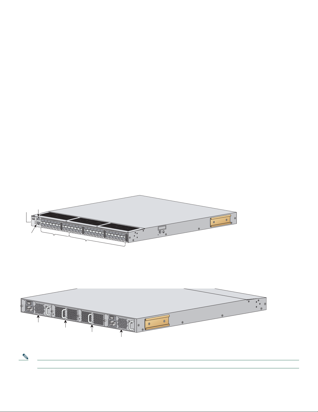
The front of the Cisco MDS 9148 Switch contains the LEDs, the console and management ports, and 48 8-Gbps Fibre Channel
Ports. See
Figure 1.
Figure 1 Front View of the Cisco MDS 9148 Switch
Console
port
LEDs
DS-C9148-16p-K9
CONSOLEMGMT 10/100/1000
STATUS
P/S
FAN
LINK
MDS 9148 Multilayer Fabric Switch
ACT
1
2
3
4
5
6
7
8
9
10
11
12
13
14
15
16
17
18
19
20
21
22
23
24
25
26
27
28
ports
29
30
31
32
33
34
35
36
37
38
39
40
41
42
43
44
45
46
47
48
253458
Ethernet
anagement
port
16 default
licensed
ports
32 on-demand
The rear of the Cisco MDS 9148 Switch contains the redundant power supplies, the AC power receptacle, and the fans.
See Figure 2.
Figure 2 Rear View of the Cisco MDS 9148 Switch
DS - C48 - 300AC
100 - 240VAC
4 - 2 A
50 - 60 Hz
INPUT
OUTPUT
OK
OK
Power
module
Fan
module
Fan
module
Power
DS - C48 - 300AC
100 - 240VAC
4 - 2 A
50 - 60 Hz
INPUT
OK
OUTPUT
OK
253459
module
Note The on-demand ports can be activated in 8-port increments through software licensing.
2

Send documentation comments to mdsfeedback-doc@cisco.com
2 Verifying Your Shipping Contents
Verify that you have received all items, including the following:
• Rack-mount kit
• ESD wrist strap
• Cables and connectors
• Any optional items ordered
3 Installing the Switch
Install the switch in one of the following enclosures:
• An open EIA rack
• A perforated or solid-walled EIA cabinet
• A two-post Telco rack
For an example of a rack mount, see Figure 3.
Figure 3 Example Rack Mount
181543
Note Before you install the switch in a rack, you will need to install the rack mount support brackets on the switch.
3

Send documentation comments to mdsfeedback-doc@cisco.com
1
4 Installing the SFPs
Install one of the following SFPs in each empty port:
• A Fibre Channel Shortwave 1-, 2-, 4-, or 8-Gbps SFP transceiver, part number DS-SFP-FC8G-SW
• A Fibre Channel Long wavelength 1-, 2-, 4-, or 8-Gbps SFP transceiver, part number DS-SFP-FC8G-LW
• A Fibre Channel Short wavelength 1-, 2-, or 4-Gbps SFP transceiver, part number DS-SFP-FC4G-SW
For SFP installation, see Figure 4.
Figure 4 SFP Installation
13 1415
16 1718 1
9 20 21 22 23 24
5 Powering Up the Switch
To power up the switch, follow these steps:
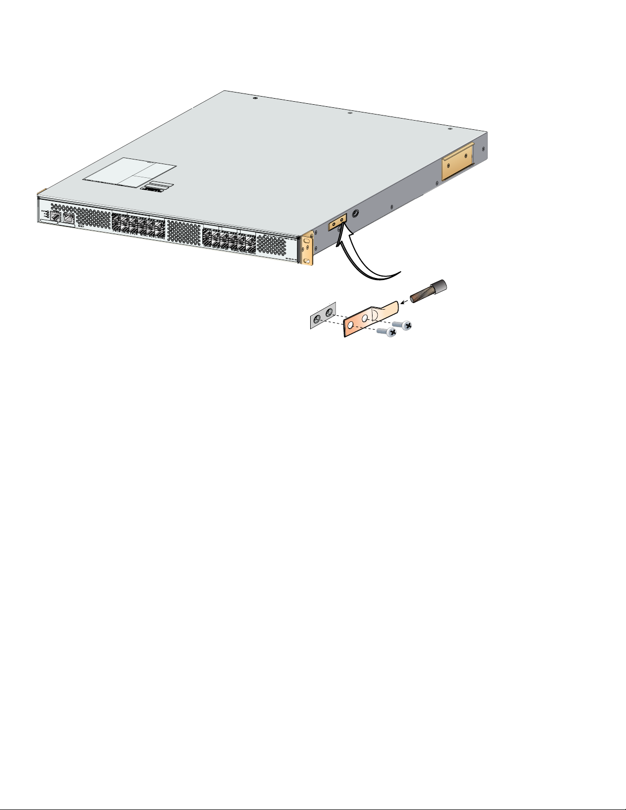
Step 1 Ground the switch, as shown in Figure 5.
81666
4
Send documentation comments to mdsfeedback-doc@cisco.com
Figure 5 Switch Ground
Grounding
pad location
System grounding pad
Wire
Grounding
lug
Screws (M4)
Step 2 Connect the power cable to the AC power receptacle, and then plug it in (see Figure 6).
The Cisco MDS 9148 Switch supports only AC power supply. The power supply status is indicated on a front panel
LED.
The Cisco MDS 9148 Switch includes a front panel reset button that resets the switch without cycling the power.
Step 3 Power up the switch (see Figure 6).
81544
5

Send documentation comments to mdsfeedback-doc@cisco.com
Teminal
1
Figure 6 Power Receptacle and On/Off Switch on Cisco MDS 9148 Switch
On/Off
switch
AC power
receptacle
274885
6 Setting Up a Network
To set up a network, follow these steps:
Step 1 Ensure that the Mgmt0 port is connected to the management network.
Step 2 Ensure that the console port is connected to the PC serial port (or to a terminal server), as shown in Figure 7. For
example, on a Windows PC used as a terminal emulator, you can use HyperTerminal. The default baud rate on the
console port is 9600.
Figure 7 Connection to Terminal Emulator.
emulator
Console port
81541
Note See Figure 1 for the physical location of the Mgmt 0 port and console ports.
6

Send documentation comments to mdsfeedback-doc@cisco.com
Web
e
253472
Step 3 Use the switch setup utility that appears on the console connection.
Step 4 Use the switch setup utility to do the following:
a. Set the admin password for the switch.
Caution Make sure that you configure a strong password. Short, easy-to-decipher passwords are not allowed by Cisco
NX-OS software. Strong passwords are at least eight characters long and contain numbers, uppercase letters,
and lowercase letters.
b. Assign an IP address and a netmask to the switch, as shown in Example 1.
Example 1 IP Address Step in the Setup Utility
Continue with Out-of-band (mgmt0) management configuration? {yes/no]: yes
Mgmt0 IPV4 address: 209.165.200.225
Mgmt0 IPV4 netmask: 255.255.255.224
c. Set up the default gateway.
Note The switch is now ready to be managed via the Mgmt port using Telnet or Device Manager or Fabric Manager.
7 Connecting Devices
To connect devices, follow these steps:
Step 1 Connect a server to the switch (see Figure 8).
Step 2 Connect a storage device to the switch (see Figure 8).
Figure 8 Server and Storage Connection
browser
Server
Storag
FC
MDS 9148
Note For more information about switch installation and configuration, see the Cisco MDS 9100 Series Hardware
Installation Guide and the appropriate CISCO MDS 9000 Family NX-OS feature configuration guides.
7

Send documentation comments to mdsfeedback-doc@cisco.com
8 Installing Cisco Device Manager
To install Cisco Device Manager, follow these steps:
Step 1 Enter the IP address you assigned to your switch in your Address field of you b rowser to begin the Cisco Device
Manager installation.
Step 2 Click the Device Manager lin k, shown in Figure 9.
Figure 9 Cisco Device Manager Installation
Step 3 Follow the onscreen instructions to install Cisco Device Ma nager.
8

Send documentation comments to mdsfeedback-doc@cisco.com
9 Using the Quick Config Wizard
To enable ports and assign zone memberships, follow these steps:
Step 1 Click the Device Manager icon on your desktop to l og in.
Step 2 Enter a password in the Password field (see Figure 10).
Step 3 Click Open (see Figure 10).
Figure 10 Device Manager Login
Step 4 Click FC, and then choose Quick Config.
Step 5 Enable two ports by checking the two corresponding check boxes in the Enable column, as shown in Figure 11.
Figure 11 Enable Zone Ports
Step 6 Select one of the two enabled ports that you want in a zone by checking its check box in the Ports Zoned To area.
When you check this check box, the second enabled port automatically becomes checked. Both ports are now members
of the same zone.
Step 7 Click Next.
You see a summary of your changes, as shown in Figure 12.
9

Send documentation comments to mdsfeedback-doc@cisco.com
Figure 12 Confirm Changes
Step 8 Click Finish to sa ve your changes.
Step 9 Repeat Steps 2 through 5 to create more zones.
Note A maximum of 12 zones with two ports each can be created with the Quick Config Wizard.
Note For more information about installing Cisco Device Manager and using the Quick Config Wizard, see the Cisco MDS
9000 Family Fabric Manager Configuration Guide.
10 Creating VSANs
To create VSANs, follow these steps:
Step 1 Click the Device Manager icon on your desktop to l og in.
Step 2 Enter a password in the Password field (see Figure 13).
Step 3 Click the Open button (see Figure 13).
10

Send documentation comments to mdsfeedback-doc@cisco.com
Figure 13 Device Manager Login
Step 4 Click FC, and then choose VSANs.
Step 5 Click Create.
Step 6 Use the Create VSAN General dialog box to create a VSAN, as shown in Figure 14.
Figure 14 VSAN Creation
Step 7 Click Finish to sa ve your changes.
Step 8 Repeat Step 6 and 7 to create more VSANs.
Note For more information on how to create VSANs, see the Cisco MDS 9000 Family CLI Configuration Guide.
This completes the installation of your Cisco MDS 9148. The switch is now ready to use.
11

Send documentation comments to mdsfeedback-doc@cisco.com
11 Need Help?
Obtaining Technical Assistance
Cisco Technical Support provides 24-hour-a-day award-winning technical assistance. The Cisco Technical Support and
Documentation website on Cisco.com features extensive online support resources. In addition, if you have a valid Cisco service
contract, Cisco T echnical Assistance Center (TAC) engineers provide telephone support. If you do not have a valid Cisco service
contract, contact your reseller.
Cisco Technical Support and Documentation Website
The Cisco Technical Support and Documentation website provides online documents and tools for troubleshooting and
resolving technical issues with Cisco products and technologies. The website is available 24 hours a day at this URL:
http://www.cisco.com/techsupport
Access to all tools on the Cisco Technical Support and Documentation website requires a Cisco.com user ID and password. If
you have a valid service contract but do not have a user ID or password, you can registe r at this URL:
http://tools.cisco.com/RPF/register/register.do
12

Send documentation comments to mdsfeedback-doc@cisco.com
13

Send documentation comments to mdsfeedback-doc@cisco.com
Americas Headquarters
Cisco Systems, Inc.
170 West Tasman Drive
San Jose, CA 95134-1706
USA
www.cisco.com
Tel: 408 526-4000
800 553-NETS (6387)
Fax: 408 527-0883
Asia Pacific Headquarters
Cisco Systems, Inc.
168 Robinson Road
#28-01 Capital Tower
Singapore 068912
www.cisco.com
Tel: +65 6317 7777
Fax: +65 6317 7799
Europe Headquarters
Cisco Systems International BV
Haarlerbergpark
Haarlerbergweg 13-19
1101 CH Amsterdam
The Netherlands
www-europe.cisco.com
Tel: 31 0 800 020 0791
Fax: 31 0 20 357 1100
Cisco has more than 200 offices worldwide. Addresses, phone numbers, and fax numbers are listed on the
Cisco Website at www.cisco.com/go/offices.
CCDE, CCENT, CCSI, Cisco Eos, Cisco HealthPresence, Cisco IronPort, the Cisco logo, Cisco Nurse Connect, Cisco Pulse, Cisco SensorBase,
Cisco StackPower, Cisco StadiumVision, Cisco TelePresence, Cisco Unified Computing System, Cisco WebEx, DCE, Flip Channels, Flip for Good, Flip Mino,
Flipshare (Design), Flip Ultra, Flip Video, Flip Video (Design), Instant Broadband, and Welcome to the Human Network are trademarks; Changing the Way
We Work, Live, Play, and Learn, Cisco Capital, Cisco Capital (Design), Cisco:Financed (Stylized), Cisco Store, Flip Gift Card, and One Million Acts of Green
are service marks; and Access Registrar, Aironet, AllTouch, AsyncOS, Bringing the Meeting To You, Catalyst, CCDA, CCDP, CCIE, CCIP, CCNA, CCNP,
CCSP, CCVP, Cisco, the Cisco Certified Internetwork Expert logo, Cisco IOS, Cisco Lumin, Cisco Nexus, Cisco Press, Cisco Systems, Cisco Systems Capital,
the Cisco Systems logo, Cisco Unity, Collaboration Without Limitation, Continuum, EtherFast, EtherSwitch, Event Center, Explorer, Follow Me Browsing,
GainMaker, iLYNX, IOS, iPhone, IronPort, the IronPort logo, Laser Link, LightStream, Linksys, MeetingPlace, MeetingPlace Chime Sound, MGX,
Networkers, Networking Academy, PCNow, PIX, PowerKEY, PowerPanels, PowerTV, PowerTV (Design), PowerVu, Prisma, ProConnect, ROSA,
SenderBase, SMARTnet, Spectrum Expert, StackWise, WebEx, and the WebEx logo are registered trademarks of Cisco Systems, Inc. and/or its affiliates in
the United States and certain other countries.
All other trademarks mentioned in this document or website are the property of their respect ive owners. The us e of the word partner does not imply a partnership
relationship between Cisco and any other company. (0910R)
© 2010 Cisco Systems, Inc. All rights reserved.
 Loading...