

Page 1

CASSIOPEIA
DT-10
Pegasus Settings
User’s Guide
Ver 1.00
Copyright© 2005 CASIO COMPUTER CO., LTD.
All rights reserved.
Page 2

変 更 履 歴
No Revision 更新日 項 改訂内容
1.00 05/2/22
1
初版
初版発行
2
3
4
5
6
7
8
9
10
11
12
13
14
15
16
17
18
19
20
21
22
23
24
25
Copyright© 2005 CASIO COMPUTER CO., LTD.
All rights reserved.
Page 3

1
Table of Content
1 PEGASUS SETTINGS FOR POCKET PCS ..............................................................................................................1
1.1 PEGASUS CARD CONFIGURATION FOR POCKET PCS ................................................................................................1
1.1.1 Status Tab..........................................................................................................................................................1
1.1.2 Configura ion Tabt
1.1.3 Advanced Settings Tab.....................................................................................................................................8
1.1.4 Ab ut Tab.........................................................................................................................................................10
1.2 NETWORK SETUP USING CONNECTION MANAGER IN PPC 2003 ............................................................................10
1.2.1 Automa ic n twork det ction.........................................................................................................................10
1.2.2 A cessing the connection manage ...............................................................................................................11
1.2.3 Advanced Connections....................................................................................................................................12
1.2.4 Network Card ..................................................................................................................................................12
1.2.5 WEP Key Entry...............................................................................................................................................13
1.2.6 Connecting to an AP .......................................................................................................................................13
1.2.7 Verifying n work connectivity......................................................................................................................14
1.2.8 P er-to-peer mod ...........................................................................................................................................15
o
t e e
c r
et
e e
.............................................................................................................................................4
Copyright© 2005 CASIO COMPUTER CO., LTD.
All rights reserved.
Page 4
1 Pegasus Settings for Pocket PCs
1.1 Pegasus Card Configuration for Pocket PCs
You need to configure the Pegasus card before you can be connected to the network. The Pegasus Configuration
1
Icon
will take you to the Status (or Configuration) window of the Pegasus wireless settings. Here you will see four
tabs: Status, Configuration, Advanced, and About tabs. The Configuration tab may not display in Pocket PC
2003 operating system because the system has its own radio scan capability (Connection Manager), and some
OEMs prefer to use the Connection Manager. The functionalities of the Status Icon will be introduced in greater
detail at the end of the chapter. The Pocket PC 2003 connection manager will be described in Chapter 1.2 .
under
Note: “Click” in this d cument actually means “tap” with a stylus on the screen of the P cket PC. Howeve , we
Start->Settings->Connections
can lead you to the configuration window. Tap on the icon
o o r
will keep the conventional usage of Click instead of Tap.
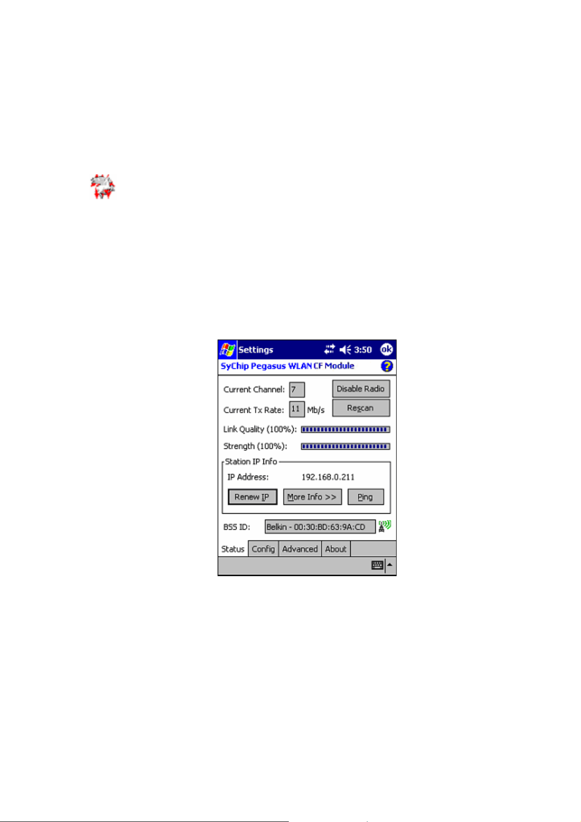
1.1.1 Status Tab
The status screen shows important parameters about the WLAN module as shown in Figure 1.
Figure 1 Status window
1.1.1.1 Information Fields
• Current Channel
Shows the RF channel currently being used by the card.
• Current TX Rate
Shows the current transmit rate. This can be 1Mb/s, 2Mb/s, 5.5Mb/s, or 11 Mb/s.
• Link Quality
Gives signal to noise ratio in both percentage and graphical display.
• Strength
Gives signal strength of the receiver in both percentage and graphical display.
Copyright© 2005 CASIO COMPUTER CO., LTD.
All rights reserved.
Page 5
2
• Station IP Info
IP Address – IP address of the card or module
Not : Check with your ne work administrator for IP configuration information. e t
• BSS ID/IBSS ID
Shows the Network Name and the MAC address of the access point the card is associated with in the AP mode.
Or it shows the Network Name and the MAC address of the creator of IBSS which the card is joined into in the
Peer-to-Peer (Ad-Hoc) mode.
•
Help button: open a context sensitive help window.
1.1.1.2 Operation Buttons
• Disable/Enable Radio
Click this button in toggle to disable/enable the radio link from the card.
• Rescan
Click on this button to start a rescan process to search for an AP with stronger signal in the network.
• Renew IP
Click this button to reapply IP address from DHCP server when automatic DHCP is enabled.
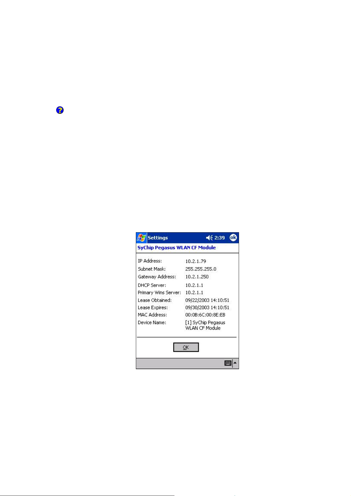
• More Info
Click this button to show detailed TCP/IP info (see Figure 2):
Figure 2 More Info window
Click OK to close this window.
• Ping
Click this button to pop up the Ping window as shown in Figure 3.
Copyright© 2005 CASIO COMPUTER CO., LTD.
All rights reserved.
Page 6
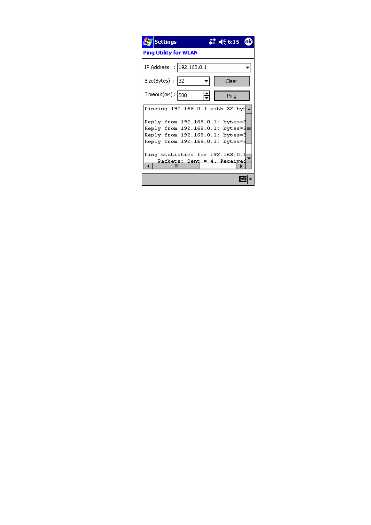
Figure 3 Ping window
3
IP Address: Enter an IP address to ping.
Size (Bytes): Choose from pull down menu from 32 to 8192 with 32 as the default.
Timeout (ms): Defaulted to 500, can be increased or decreased from the spin button.
Clear: Click this button to clear IP Address input and the ping statistics field.
Ping: Click on this button to ping the IP address entered in the input field.
Ping Statistics Field: Shows the pinging IP address and the pinging results.
Copyright© 2005 CASIO COMPUTER CO., LTD.
All rights reserved.
Page 7
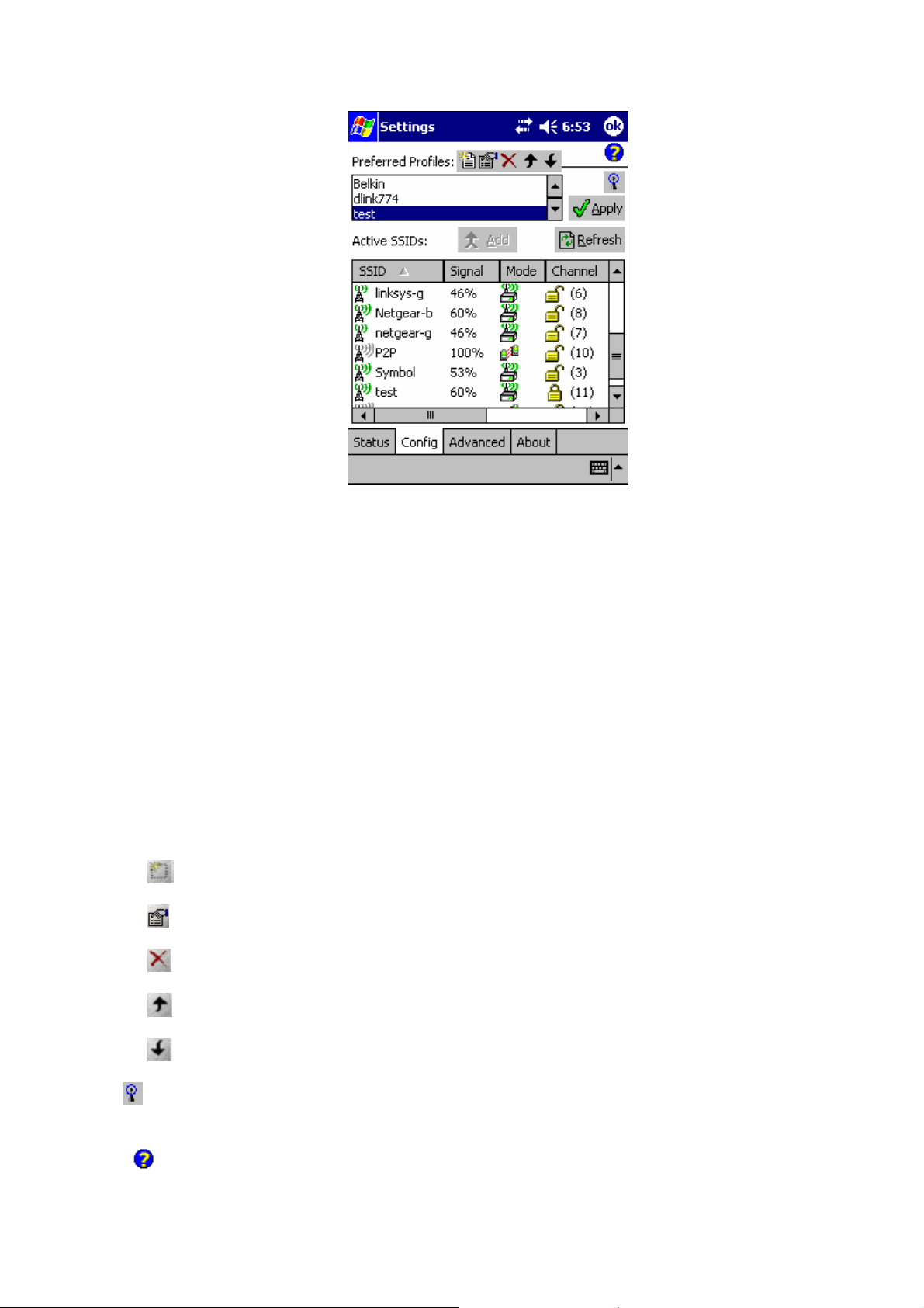
1.1.2 Configuration Tab
4
Figure 4 Configuration window
This window provides
1) Periodically updated scanning results in the Active SSIDs window that lists all the access points and peer
stations available around the host.
2) A configuration tool that enables you to create and edit SSID profiles for your station to associate or join
with.
1.1.2.1 Information Fields
• Preferred Profiles
On the top of the window is a list of preferred profiles one has created, or added from the Active SSIDs table
below. Whenever the radio is turned on, it will start searching for the APs to associate with in the order of the
listed profiles. This table is blank after the initial Pegasus software installation. It can be kept blank with no
automatic association preference. For each profile in the table, one can make changes by using icon tools on top
of the table: New, Edit, Delete, Up, and Down.
Five small icon buttons on the top of the table can be used to create or modify Preferred Profiles:
New: create a profile (for detailed info see Section 1.1.2.3).
Edit: modify a profile (for detailed info see Section 1.1.2.3).
Delete: delete a selected profile (for detailed info see Section 1.1.2.4).
Up: move the highlighted profile up to increase the automatic association priority.
Down: move the highlighted profile down to decrease the automatic association priority.
WZC button: Shortcut for Windows Zero Configuration (wireless automatic configuration), available on
Pocket PC 2003 and later versions.
Help button: open a context sensitive help window.
Copyright© 2005 CASIO COMPUTER CO., LTD.
All rights reserved.
Page 8

5
• Active SSIDs
The Active SSIDs table lists all the access points or peer stations (creator of IBSS) in the vicinity with each
record displaying the following six fields (The table may not display all the fields on the screen. Use horizontal
scroll bar to check all):
SSID – Network Name of the access point or peer station. A link icon with signal strength
shown.
Signal – Signal Strength in percentage for that SSID.
Mode – An icon shows whether it is an access point
Channel – The channel being used and the WEP key status. (
for WEP Key-Off).
SupRate – Supported data rate of the access point or the peer station.
BSSID (MAC Addr) – BSSID or MAC Address of the access point or the peer station.
, or a peer station .
stands for WEP Key-On, and
1.1.2.2 Operation Buttons
• Add
Click on this button to add the selected (highlighted) profile into the Preferred Profile table. If the SSID has
WEP Key On, the Settings window will pop up for you to enter the WEP Method, Encryption Key, and Key ID.
Click OK button in the Settings window after finishing the configuration, and the SSID with its profile will be
added into the Preferred Profiles window. No window will pop up when adding an SSID with WEP Key Off. It
will be added into the Preferred Profile table directly at the click on Add button.
• Apply
is also
Click this button to associate/join your station with the SSID you selected. This SSID can be either from the
Preferred Profile or from the Active SSIDs table. When Applied, the Status tab window will display the status
of the wireless connection. If the association fails, an automatic search for another AP in the preferred profile
list will take place, trying to associate in the order of your preference.
• Refresh
Click this button to start a new search for all available access points or peer stations in the vicinity.
1.1.2.3 Profile Settings Window
Tapping on the New or Edit button to enter the profile setting window. It has two tabs.
To create a new profile to the preferred list one can click the New button (described in Section 1.1.2.1) without
selecting (highlighting) any existing profile
5.
To modify a profile one can select (highlight) a profile and click the Edit button. A Modify Existing Preferred
SSID window will pop up as shown in Figure 5, except that the SSID, Type, TX Rate, and Channel fields are
unchangeable in AP mode, whereas TX Rate and Channel fields can be changed in Peer-to-Peer mode.
1.1.2.3.1 Network Profile Tab
.
An Add New Preferred SSID window will pop up as shown in Figure
Copyright© 2005 CASIO COMPUTER CO., LTD.
All rights reserved.
Page 9

6
Figure 5 Network profile tab
The information fields and operation buttons are listed as follows:
Network Name & Type block: Used to create SSID with a network Type, and to configure the transmit data rate
at certain channel.
• SSID: to enter an SSID, which is the Network Name.
Check with your network administrat for Network Name (SSID). or
• Type: Choose from Peer-to-Peer or Access Point in the pull down menu. Access Point (AP) mode is also
called “Infrastructure” mode. Peer-to-Peer (P2P) mode is used for communication between two (or more)
radio stations (cards) without an access point.
• Tx Rate: Choose 1Mb, 2 Mb, Auto 1/2 Mb, 5.5 Mb, 11 Mb for P2P connection, or Fully Auto for AP
connections from the menu. The transmit rate is Fully Automatic by default.
• Chan: Channel. Scroll to select a channel for communication.
• AP Search Threshold: Used to adjust the wireless client roaming behavior between APs.
From the option menu choose Low Density (default), Medium Density, or High Density, and tap on OK
button. By increasing the values from Low to High, your WLAN card tends to roams earlier from one AP to
another (with the same SSID in the same network) depending on the APs' relative signal strength.
• OK: Click this button to make the change.
• Cancel: Click this button to close the window without saving or modification.
1.1.2.3.2 Authentication Tab
Copyright© 2005 CASIO COMPUTER CO., LTD.
All rights reserved.
Page 10
7
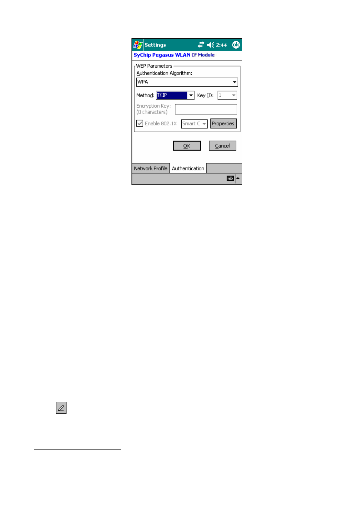
Figure 6 Authentication tab
o Authentication Algorithm - Five options, only configurable when WEP Method is enabled.
1. WECA Compliant (always use Open) - Should match AP's setting for "Open."
2. Must use Shared with WEP - Should match AP's setting for "Shared."
3. Automatic based on WEP setting - Automatically matches AP's setting.
4. WPA-PSK - Need Pre-Shared Key for access.
1
5. WPA
- Need network certificate for authentication.
o WEP Method - Five options for WEP Key encryption.
1. Disabled - WEP Key Off
2. 64 bit (HEX) - 10 characters configurable in Hexadecimal
3. 64 bit (ASCII) - 5 characters configurable in ASCII
4. 128 bit (HEX) - 26 characters configurable in Hexadecimal
5. 128 bit (ASCII) - 13 characters configurable in ASCII
6. TKIP - Only used when WPA is selected.
NOTE: HEX - Hexadecimal number set of 16 digits from 0-9, and from A(a)-F(f). ASCII - Any
printable ASCII characters.
o Key ID - Four options can be selected: Key 1, 2, 3, and 4. The default is Key 1.
1
WPA security implementation is targeted at enterprise markets only. In order to activate, a certificate
enrollment program must be installed from the company’s IT department in order to obtain the user’s
personal certificate.
Copyright© 2005 CASIO COMPUTER CO., LTD.
All rights reserved.
Page 11

8
o Encryption Key - Input character set depending on WEP method and key format.
o Enable 802.1X - Check the box if access to the network needs group authentication. Only configurable
when WEP Method is enabled. From the pull-down menu select the 802.1X security standard, PEAP or
Smart Card (TLS). Tap on the Properties button to choose the certificate that applies. To access a 802.1x
2
network you need to enroll and get the personal certificate first. Use the Certificate Enrollment program
in your PDA to provide the domain name, server name, user name and password required by the
authentication server. This security feature is available on Pocket PC 2003.
o OK - Tap on this button to make the change.
o Cancel - Tap on this button to close the window without saving or modification.
1.1.2.4 Delete Preferred List Window
A profile can be deleted either from the Preferred List or from the Preferred List and the Registry altogether. First
select (highlight) the profile you want to delete in the Preferred Profile table, then click on the Delete button
(described in Section 1.1.2.1) to pop up the Delete Options window as shown in Figure 7. From the pop-up window
select the option of your choice and click Yes button to confirm, or No button to cancel.
Figure 7 Delete Preferred List Options Window
1.1.3 Advanced Settings Tab
2
See above.
Copyright© 2005 CASIO COMPUTER CO., LTD.
All rights reserved.
Page 12
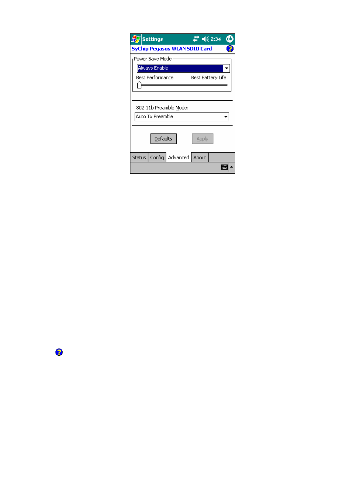
Figure 8 Advanced Settings Window
9
1.1.3.1 Information Field
• Power Save Mode
Disable – Choosing this option will disable the power save mode.
Always Enable – Choosing this option will have the power save mode always enabled. This is the
default setting.
Auto Enable – When internal battery is being used it will be in Power Save mode; when external
power supply is being used the Power Save mode will be disabled automatically.
• Preamble Mode
Long TX Preamble – Where Sync field consists of 128 bits.
Short TX Preamble – Where Sync field consists of 56 bits.
Auto TX Preamble – Automatically change between long and short preamble mode transmission
based on the AP configurations. This is the default Preamble Mode.
Not : A Preamble consists of a Synchronization (Sync) field and a 16-bit Start Frame Delimiter (SFD)
e
field.
• Help button
Open a context sensitive help window.
1.1.3.2 Operations
• Sliding bar
B st P rformance
The leftmost position on the sliding bar (
every beacon from the associated AP. The default beacon interval is 100 ms for most APs. When the knob is
dragged to the right-hand-side, the station will listen to the beacon in multiple beacon intervals depending on
the position on the slide bar. The rightmost position (Best Battery Life) indicates the beacon interval is 10
times of AP’s beacon interval, i.e. 1000 ms when the beacon interval is set to 100ms. For the Sliding bar to take
effect, the
Apply
Power Save Mode
button.
needs to be either
Copyright© 2005 CASIO COMPUTER CO., LTD.
e e
Alway Enable
All rights reserved.
) indicates that the WLAN station will listen to
or
s
Auto Enable
, and you need to click on the
Page 13
• Defaults Button
Reset all the settings to default values (Always Enable for Power Save Mode, Automatic based on WEP setting
for Authentication Algorithm, and Auto TX Preamble for Preamble Mode).
• Apply Button
Apply the change to new card setting.
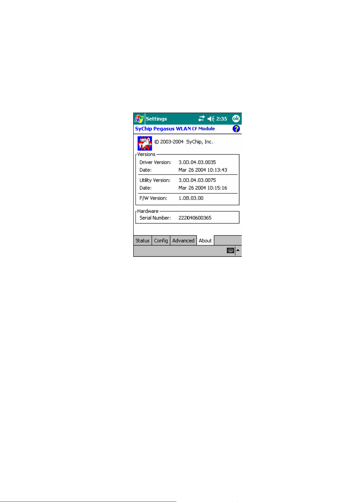
1.1.4 About Tab
10
Figure 9 About Window
This window provides Version Number and time of build for Network Driver, Configuration Utility, and NIC
Firmware, and the module Serial Number.
1.2 Network Setup using connection manager in PPC 2003
The connections manager plays a generic role for managing various network connections. For WLAN access,
Pegasus configuration described before for Pocket PC 2002 (Section 1.1 ) still works. A second way of
configuration is also available using the default Pocket PC 2003 connection manager (Wireless Zero
Configuration or WZC).
1.2.1 Automatic network detection
• The PPC 2003 connection manager scans for wireless networks periodically. When it detects any network
and it has not connected to any network yet, it will first try to connect to one of the preferred networks. If
such a network is not available or the connection manager can not connect to any preferred network due to
invalid WEP key, it will popup a window and shows a list of networks for you to choose. See Figure 10. If
you don’t see the network of your choice, click on
(Figure 14).
Note: If the connection manager is able to connect to a network automatically, the Network Detection
Window (Figure 10) will not appear, and you can follow the steps described in Section 1.2.2 to access the
connection manager.
Settings
to get to the detailed configuration window
Copyright© 2005 CASIO COMPUTER CO., LTD.
All rights reserved.
Page 14

Figure 10 Network Detection
11
• Select your network and what the network will connect to. In most cases, you should select
Work.
you are connecting to work network, select
would like to use the Pegasus
Configuration GUI (Section 1.1 ) instead, click on
If you do not wish to use the connection manager and
• Now click on
will popup for you to enter the WEP key. Enter the WEP key then click on
connection should be established.
Conne t.
c
If WEP is disabled, then the connection should be established, otherwise, a window
Connect
The Internet.
Hide.
. See Figure 11. The
If
Figure 11 WEP key entry
1.2.2 Accessing the connection manager
Click on the Connectivity icon to bring up the connection manager. See Figure 12.
Copyright© 2005 CASIO COMPUTER CO., LTD.
All rights reserved.
Page 15

Figure 12 Connectivity Settings
12
1.2.3 Advanced Connections
Click on
Settings
link, and select
Advanced tab
. You will see the following screen. Alternatively, you can follow
Start->Settings->Connections->Connections icon ->Advanced Tab
Figure 13 Advanced Connections Window
to get to the same screen.
1.2.4 Network Card
Click on
selected under
on the screen shown in Figure 14.
Network Ca d
r
Netwo k to a cess.
r s c
button and select
Wireless
A list of Access Points and their connectivity/availability status will appear
Copyright© 2005 CASIO COMPUTER CO., LTD.
All rights reserved.
tab. Make sure “
All Available
” or “Only access points” is
Page 16

Figure 14 Configure Wireless Networks
13
1.2.5 WEP Key Entry
Click on the AP you want to connect to, a configuration screen will appear. Then select the
See Figure 15.
If WEP is enabled on the AP, check the first checkbox, which is “
need to obtain the WEP key and key index from your network administer, put the key string in the textbox
labeled “
enabled, then leave the “
Network key
”, and select the
Data encryption
Key index
” unchecked. Click on OK to return to the previous screen (Figure 14).
from the choice box (the default key index is 1). If WEP is not
Data encryption (WEP Enabled)
Authentica ion
t
”. Now you
tab.
Figure 15 Configure Network Authentication
1.2.6 Connecting to an AP
Tap and hold on the AP entry you wish to connect to, and select
Figure 16. The LED on the WLAN module should start to blink, indicating it is trying to associate, and
eventually turn green, which means it is connected successfully. The screen will also be updated to show the
Copyright© 2005 CASIO COMPUTER CO., LTD.
All rights reserved.
Connect
option on the popup menu as shown in
Page 17

new connection. See Figure 17.
14
Figure 16 Connecting to an AP
Figure 17 Connection to a new AP
1.2.7 Verifying network connectivity
If the Pocket PC is not connected with a host PC via a sync cable, then the Connectivity icon normally
Netwo k Adapte s
indicates the WLAN connection is properly established. You can also check on the
check if the IP address obtained from DHCP is correct. See Figure 18, click “SyChip Pegasus WLAN CF Module”
to see the IP address information (Figure 19).
Copyright© 2005 CASIO COMPUTER CO., LTD.
All rights reserved.
r r
tab to
Page 18

Figure 18 Network adapter status
15
Figure 19 IP address
1.2.8 Peer-to-peer mode
Peer-to-peer mode is also known as the “Ad-Hoc” mode. There are two ways for your device to connect to other
devices in peer-to-peer mode. The first way is that you create an Ad-Hoc network on your device, and then allow
other devices to connect to yours by joining the network. The second way is simply connect your device to an
existing Ad-Hoc network, if such network is already created by the peer device.
1.2.8.1 Creating an Ad-Hoc network from your dev ice
1. Get to the
choice box to
Figure 20.
Configure Wireless N tworks
e e e
Only computer-to-computer
Copyright© 2005 CASIO COMPUTER CO., LTD.
All rights reserved.
screen as shown in Figure 14. Change the
. Select
Add New S ttings
e
… under
Wireless networks
N tworks to acc ss
. See
Page 19

16
Figure 20 Configuring an Ad-Hoc network
2. Type in the network name in the
a device- o-compute (Ad-H c) connection.
t r o
Network Name
field (
txtest,
for example). Then check the box
This is
Copyright© 2005 CASIO COMPUTER CO., LTD.
All rights reserved.
Page 20

Figure 21 Creating a new Ad-Hoc network
17
3. OK to go back to the previous screen. Click and hold the network name and select
connect
.
Figure 22 Connecting to the Ad-Hoc network
4. Now the new Ad-Hoc network has been created, and it is visible to other WLAN devices. Your device
is connected to the Ad-Hoc network as shown in Figure 23.
Copyright© 2005 CASIO COMPUTER CO., LTD.
All rights reserved.
Page 21

Figure 23 Connected to the Ad-Hoc network
18
1.2.8.2 Connecting other devices to the Ad- Hoc network
Once the Ad-Hoc network is created, it is available for other devices to join. To join the network, go to the
Configure Wir less N works
(Figure 23), the second device should now be connected to the newly created Ad-Hoc network, e.g.
can go to the connection
network should be able to ping each other. You can add more devices to the Ad-Hoc network by performing the
same procedure so that they form a closed network among themselves.
e et
screen (Figure 22) using a second device. Repeat step 3 (Figure 22) and step 4
txtest
Status
screen (Figure 1) to find the devices’ IPs. The two devices on the same Ad-Hoc
. You
Copyright© 2005 CASIO COMPUTER CO., LTD.
All rights reserved.
Page 22

19
DT-10
Pegasus Settings for Pocket PCs
Ver1.00
発行元:カシオ計算機株式会社
〒162-8543
東京都渋谷区本町 1-6-2
システムソリューション営業統轄部
TEL:03-5334-4638
Copyright© 2005 CASIO COMPUTER CO., LTD.
All rights reserved.
 Loading...