

Page 1
DR-120LB (ZX-517C)
DL-200L (ZX-517A)
DL-210L (ZX-517B)
DR-320B (ZX-517D)
JULY 1996
(without price)
DR-120LB DR-320B
R
Page 2

CONTENTS
1. SPECIFICATIONS......................................................................................................... 1
2. BLOCK DIAGRAM ........................................................................................................ 1
3. CPU (MN15418YCY) PIN FUNCTION ...........................................................................2
4. DIAGNOSTIC ................................................................................................................ 3
5. TROUBLESHOOTING .................................................................................................. 4
6. DISASSEMBLY VIEW................................................................................................... 5
7. SCHEMATIC DIAGRAMS ............................................................................................. 6
8. PARTS LIST ................................................................................................................ 10
Page 3
1. SPECIFICATIONS
Functions: 4 basic arithmetic operations (+, –, ×, ÷), constants for ×/÷, sub-total/
total/grand total, item counting, ADD mode calculations, repeat calculations, memory calculation, percentage calculations and various
kinds of practical calculations.
Decimal point: Full floating, and fixed (0, 1, 2, 3, 4, or 6) with round off, round-up cut-
off.
Capacity: 12 digits
Ambient temperature range: 0 °C ~ 40 °C (32 °F ~ 104 °F)
Power supply: (AC 120 V, 100/120 V, 230/240 V)
Rated current and voltage are printed on the calculator.
Dimensions: 75.1 (H) × 212 (W) × 358 (D) mm
(3" H × 8 3/8" W × 14 1/8" D) including roll-holder
Weight: 1.5 kg (3.3 lbs)
Consumable supplies: Printer ribbon (RB-02 or GB-02)
Roll papaer (Width 58 × 60 ø mm)
The AC outlet must be located near the unit and must be easily accessible.
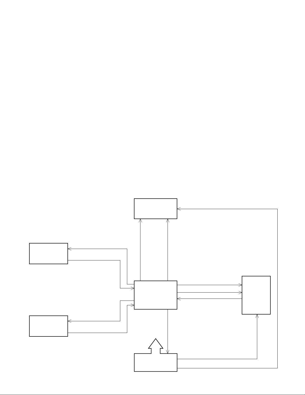
2. BLOCK DIAGRAM
Display tube
13-BT-144G
Sent signal
S1~S7, SAP, SDP
SO1~SO7
Slide switch
SI1~SI3, SI5
CPU
MN158418YCY
KO1 ~ KO8
Keyboard
KI1 ~ KI6
VDD (32 V, 30 mA)
VSS (27 V, 30 mA)
VF1 (5.9 V, 100 mA), VF2 (2.0 V, 100 mA)
Digital signal
D1~D13
Ribbon shift signal
Character selective signal
Timing pulse
Motor control signal
Printer
M-80
VM (11 V, 200 mA)
VDD
Power supply
circuit
— 1 —
Page 4
3. CPU (MN158418YCY) PIN FUNCTION
Pin No. Signal I/O Function
1 ~ 7, 64 P00 ~ P13 Out Common signal for keyboard
8 ~ 12 P20 ~ P22, P32, P33 In Key signal from keyboard
13 IR Q In Timing pulse signal from printer
14 DEBIN In Reset p u l s e ( N o t u s e d )
15 IRQCN T In Auxiliary timing (VDD)
16 P40 Out Motor control signal
17 P41 Out Ribbon shift signal for printer
18 ~ 30 P42, P43, P50 ~ P53, Ou t Character selective signal for printer
P70 ~ P73, P80 ~ P82
31, 32 P83, P90 Ou t Segment signal for display,
Character selective signal for printer
33 ~ 39 P91 ~ P93 Out Common signal for slide switch,
PA0 ~ PA3 Segment signal for display
40 P60 In Input port (VDD)
41 ~ 43 P61 ~ P63 In Signal from slide switch
44 ~ 56 PB0 ~ PB3, Ou t Digit signal for display
PC0 ~ PC3,
PD0 ~ PD3,
PE0
57 VPP In GND terminal
58 VDD In VDD terminal (+32 V)
59, 60 OSC1, OSC2 I/O Clock signal for CPU
61 VSS In VSS terminal (+27 V)
62 SYNC — Not used
63 RST In Signal from slide switch, Reset signal
— 2 —
Page 5
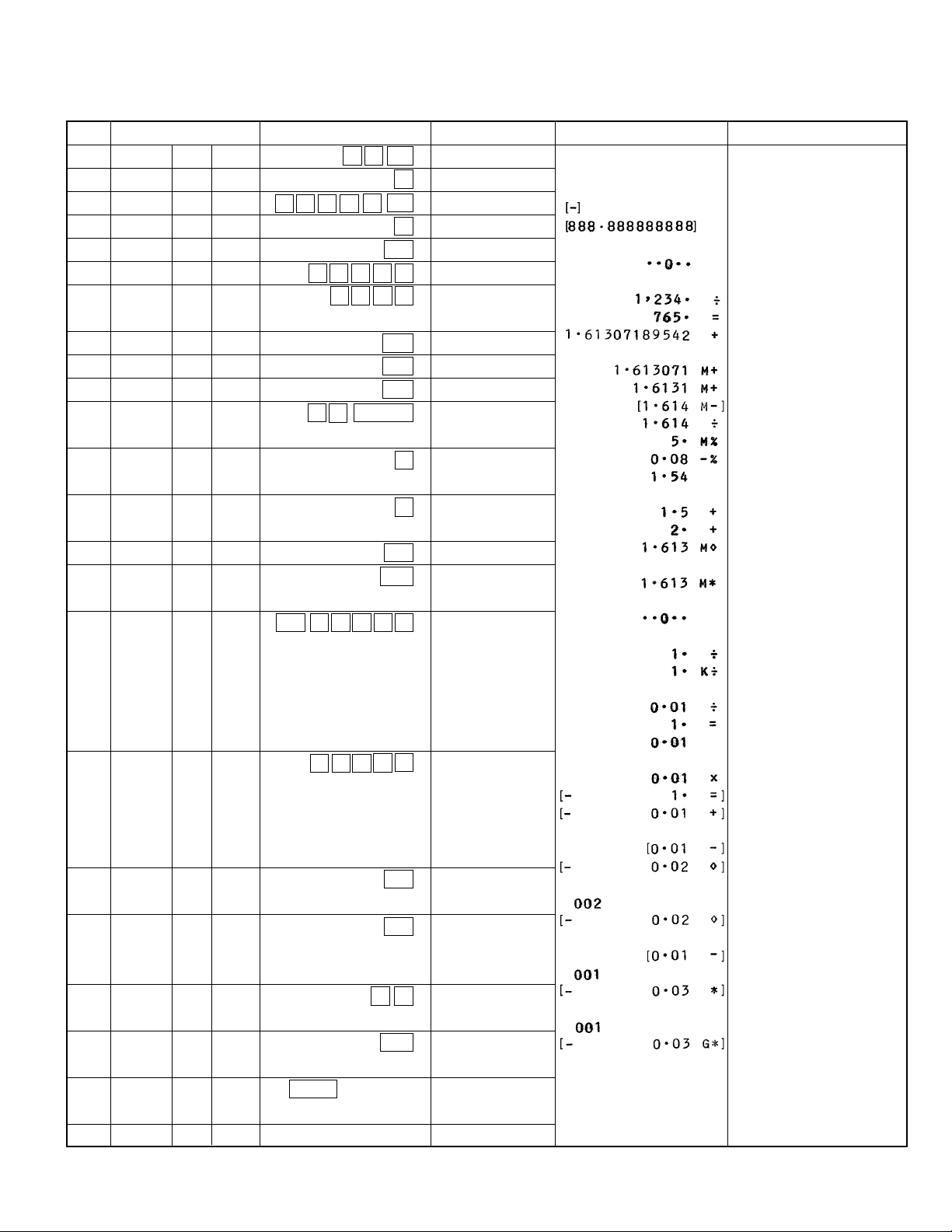
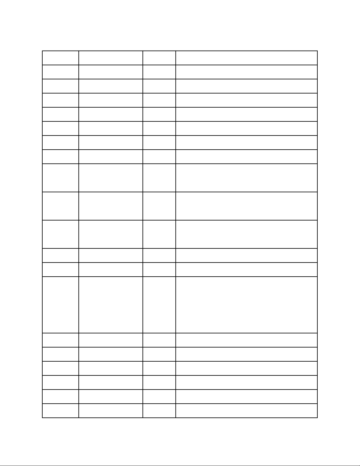
4. DIAGNOSTICS
STEP
1
2
3
4
5
6
7
8
9
10
11
12
13
14
15
MODE SWITCHES
ON F 6
ON F 6
ON F 6
ON F 6
PRINT F 6
PRINT F 6
PRINT F 6
PRINT CUT 6
PRINT UP 4
PRINT UP 3
PRINT UP 2
PRINT 5/4 1
PRINT 5/4 0
PRINT 5/4 ADD×
PRINT 5/4 ADD×
OPERATION
1 0 00
8 – ÷ 9 % ◊/#
CA
1 2 3 4 ÷
7 6 5 +
M+
M+
M–
÷ 5 MU/MD
M◊
M❊
C
-888.888888888
▲
+
+
-888.88888888
1.61307189542
M 1.613071
M 1.6131
M 1.614
M 1.54
M 3.1
M 5.
DISPLAY
1000.
1234.
1.613
1.613
0.
0.
PRINT
NOTE
The character with "[ ]"
will be printed by red
ink.
16
PRINT 5/4 ADD×
17
PRINT 5/4 ADD+
18
PRINT 5/4 ADD+
19
ITEM+ 5/4 ADD+
20
ITEM+/– 5/4 ADD+
21
ITEM+/– 5/4 ADD+
CA 1 ÷ ÷ 1 =
× 1 – 1 –
◊/#
◊/#
– ❊
G❊
K 0.01
–0.02
–0.02
–0.02
–0.03
–0.03
22
ITEM+/– 5/4 ADD+
23
OFF
FEED
NO Display
— 3 —
Paper feeding
Press the button 3
seconds continuously.
Page 6

5. TROUBLESHOOTING
Trouble Cause Checkpoint Note
1) Does not work
at all.
• Defective power transformer
Secondary voltage
of transformer
VDD, VSS, VM, VF1, and
VF2 are OK?
2) No display.
3) No print.
4) Poor display.
5) Poor printing
• Motor does
not stop.
• Defective LSI
• No voltage at VF1, VF2
• No digit signal or no segment
signal
• Defective display tube
• Poor voltage VM
• Defective motor
• Defective LSI
•Short or open circuits between
digit signals and segment signals.
• Defective display tube
• Timing signal is bad.
Waveforms of each
pin
VF1, VF2
Signal D1 ~
S1 ~
Between LSI and
display tube
Check the pulse signals
from LSI.
If VF1, VF2, Digit and
Segment signals are OK.
VM = 11 V±5 % (while printing)
Check detector of printer
block and timing signal.
• Missing of
digits.
• Defective printer magnet
• Refer to the printer service manual published separately.
— 4 —
Page 7

9
8
10
11
20
6
16
15
19
18
17
13
14
12
4
1
2
3
5
7
6. DISASSEMBLY VIEW
— 5 —
Page 8

7. SCHEMATIC DIAGRAMS
7-1. Main PCB
POWER CORD
286S0255-1 (USA, CANADA)
EP-483-E03 (EUROPE, SAUDI)
SP-852-J03 (AUSTRALIA)
TR
SE-225-1D1U (USA, 120 V)
SE-225-1D1J (JAPAN, CANADA, 100/120 V)
SE-225-1D2 (EUROPE, 230/240 V)
— 6 —
Page 9

7-2. Keyboard PCB
— 7 —
Page 10

7-3. Slide Switch Board PCB
— 8 —
Page 11

7-4. Printer Pin Arrangement Diagram
Connection Pin No. ConnectionPin No.
RD terminal
1
Character selective
15
magnet column No.1
(Not used)
Character selective
magnet column No.1
2
3
4
5
6
7
8
9
10
10
11
12
2
3
4
16
17
18
13
14
15
Notes:
1. Column numbers match
5
19
16
the physical arrangement of the columns on
the print wheels.
6
20
17
2. Column numbers are assigned from 1 to 18 from
Ribbon shift magnet
7
21
the frame motor side.
3. Pin numbers are assigned from 1 to 27 from
8
22
Electromagnet (+)
the frame motor side.
4. The spark arrestor diode
is connected as shown
9
M
23
Motor power
supply (+)
24
Detector power
supply (+)
Timing signal
25
Detector power
26
supply (–)
below.
Electromagnet (+) Driver
(Example of compatible diode:
1S2075K or equivalent)
Motor power
11
13
27
supply (–)
14
12
Motor power ON/OFF
Timing signal
Character selective magnet No.n
T0 T1 T2 T3 T4 T5 T6 T7 T8 T9 T10 T11 T12
*2
8.0ms min. 2.0ms min.
0.7ms max.0.7ms max.
0.7ms max.0.7ms max. 80.0ms min.
8
0.2ms max.
*1
TS T(0)
Ribbon shift magnet
(Print operation)
(Normal paper feeding operation)
Typ. 285.7ms
Notes:
1. The signals in must be prepared by the user.
2. The pulse is indicated by a dot-dash line (*1) is generated for continuous printing. The next print cycle can start
immediately after the leading edge of the timing signal Ts.
3. As shown by a dashed line (*2), the timing signal may go low at motor power-on or upon reception of a Print command.
— 9 —
Page 12

8. PARTS LIST
N Item Code No. Parts Name Specification Q R
ABCD
LSI 2012 1295 LSI MN158418YCY
IC1, 2 2114 2436 Monolithic IC(Buffer) BA12003
Q1 2251 0525 Transistor 2SB1329-Q,R
Q2 2253 0469 Transistor 2SD1380-Q,R (ROHM)
Q3, 4 2252 0896 Transistor 2SC1740S-R,S
Q5 2250 0672 Transistor 2SA933S-R,S
Q6 2251 0581 Transistor 2SB1374-Q,R
Q7, 8 2259 1449 Digital transistor DTD114ES
D1~5 2390 0378 Diode 1SR139-100T-32-T
D6~8 2360 1946 Zener diode MTZJ5.6CT-77-T
D9~11 2301 0054 Diode 1S2472-T-77-T
D13, 14 2301 0101 Diode 1S2473-T-77-T 2222C
DIG1 3301 0217 Display tube 13-BT-144G
The following elecrical parts will be not supplied from CASIO.
1111
2222
1111
1111
2222
1111
1111
2222
5555
3333
3333
1111
B
B
B
B
B
B
B
B
C
C
C
A
C1 2845 3241 Semiconductive capacitor DD308-959F104Z50
C2 2803 9198 Electrolytic capacitor RE2-50V331M-T2
C3 2803 8199 Electrolytic capacitor RE2-25V222M-T50
C4 2813 3178 Semiconductive capacitor DD003-298B102K50
C5 2803 9197 Electrolytic capacitor RE2-16V100MA-T2
C6 2845 2170 Semiconductive capacitor DD308-959F224Z12
C7, C8 2813 3038 Semiconductive capacitor DD003-298SL101J50
R1 2606 1351 Carbon film resistor R-50X-6.8K-J-T24-T (6.8 Kohm, 1/2 W, ±5%)1111
R2 2606 2297 Carbon film resistor R-50X-5.6k-J-T24-T (5.6 K, 1/2 W, ±5%) 1111
R5 2614 0323 Carbon film resistor R-25-3.3K-J-T24-T (3.3 Kohm, 1/4 W, ±5%) 1111
R6 2614 0048 Carbon film resistor R-25-15K-J-T24-T (3.3 Kohm, 1/4 W, ±5%) 1111
R7 2614 0234 Carbon film resistor R-25-1K-J-T24-T (1 Kohm, 1/4 W, ±5%) 1111
R8 2614 0561 Carbon film resistor R-25-3.9K-J-T24-T (3.9 K-2) 1111
R9 2614 0579 Carbon film resistor R-25-470-J-T24-T (470 ohm, 1/4 W, ±5%) 1111
R10 2614 0471 Carbon film resistor R-25-270-J-T24-T (270 ohm, 1/4 W, ±5%) 1111
R11 2614 0188 Carbon film resistor R-25-390-J-T24-T (390 ohm, 1/4 W, ±5%) 1111
R12 2614 0749 Carbon film resistor R-25-5.1K-J-T24-T (5.1 K-2) 1111
R13 2621 6397 Carbon film resistor R-50X-22-J-T24-T (22 ohm, 1/2 W, ±5%) 1111
R14 2606 1344 Carbon film resistor R-25-6.8K-G-T24-T (6.8 K, 1/2 W, ±5%) 1111
R15 2614 1311 Carbon film resistor R-25-200-J-T24-T (200 ohm, 1/4 W, ±5%)
R17~R20 2775 3264 Metal film resistor RSMF1B220J (100 ohm, 1 W, ±5%)
COMPONENTS
N 1 6419 4320 PC joiner B-V298 HA310361-2
N 2 1014 9622 DIGITAL PRINTER M-80-021
N 3 6419 4130 UPPER CASE-Z517A HA110103-1
N 3 6419 4140 UPPER CASE-Z517B HA110103-2
N 3 6419 4150 UPPER CASE-Z517C HA110103-3
N 3 6419 4310 UPPER CASE-Z517D HA110103-4
N 4 6419 4160 LOWER CASE-Z517A HA110104-1
N 4 6419 4170 LOWER CASE-Z517B HA110104-2
N 4 6419 4180 LOWER CASE-Z517C HA110104-3
N 5 6419 4660 PRINTER COVER-Z517A HA110106-1
N 5 6419 4670 PRINTER COVER-Z517B HA110106-2 0111C
N 6 6419 4200 PAPER CUTTER-Z517 HA210052-1 1111C
N 7 6419 4190 SLIDE SWITCH-Z517 HA210051-1 3333X
N 8 6419 4220 KEY A-Z517 HA110107-1 1111C
Notes: N – New parts A: DR-120LB
Q – Quantity used per unit B: DR-320B
R – Rank C: DL-210L
— 10 —
1111
1111
1111
1111
1111
1111
2222
1111
4444
1111
1111
1000
0100
0010
0001
1000
0100
0011
1000
D: DL-200L
C
A
X
X
X
X
X
X
X
C
Page 13

N Item Code No. Parts Name Specification Q R
ABCD
N 9 6419 3040 KEY B-Z517 HA310265-1
N 10 6419 3050 KEY C-Z517 HA310266-1
N 11 6419 3020 DISPLAY PLATE-Z517A HA1101105-1
N 12 6419 4240 C FILM-517 HA310352-1
N 13 6419 4250 SW SPACER-Z517 HA310351-1
14 6329 8310 CONTACT PLATE-G310 A45208-1
15 3012 1337 TRANSFORMER SE-225-1D1U (or T03411C)
15 3012 1316 TRANSFORMER SE-225-1D1J (or T03410D)
15 3012 1323 TRANSFORMER SE-225-1D2 (or T03412A)
N 16 3701 1114 POWER CORD 286S0255-1
N 16 3701 1106 POWER CORD EP-483-E04
N 16 3701 1115 POWER CORD SP-852-J03
N 17 6419 3030 RUBBER KEY-Z517 HA210062-1
N 18 4321 2280 PCB-Z517-2 HA210060-1
N 19 6419 4290 PC JOINER A-Z517 HA310361-1
1111
1111
1111
1111
1111
6666
1100
1010
0011
1110
0011
0010
1111
0111
1111
OTHERS
20 6416 8960 Roll arm R-L227B P340017-2
20 6416 8970 Roll arm L- L227B P340024-2
N 20 6419 5000 Roll arm R-L227A P340017-1
N 20 6419 5010 Roll arm L- L227A P340024-1
1000
1000
0111
0111
The Parts prices will be informed separately by Parts Price List.
C
X
X
X
C
C
B
B
B
C
C
C
C
X
X
A
A
A
A
Notes: N – New parts A: DR-120LB
Q – Quantity used per unit B: DR-320B
R – Rank C: DL-210L
D: DL-200L
— 11 —
Page 14

MA0900461A
 Loading...