

Page 1

(without price)
CFX-9850G PLUS (ZX-935A)
MAY. 1997
CFX-9850G PLUS
R
Page 2

CONTENTS
1. SPECIFICATIONS ........................................................................................... 3
2. GENERAL GUIDE
2-1. Modes....................................................................................................... 4
2-2. Color Contrast Adjustment .................................................................... 5
2-3. Power Supply .......................................................................................... 6
3. RESET OPERATION....................................................................................... 9
4. DATA COMMUNICATIONS
4-1. Connecting Two Units .......................................................................... 10
4-2. Before Starting Data Communications ............................................... 10
4-3. Performing Data Transfer Operation................................................... 11
4-4. To Send the Screen .............................................................................. 14
4-5. Data Communication Precautions ...................................................... 15
5. OPERATION CHECK .................................................................................... 16
6. DATA TRANSFER CHECK........................................................................... 19
7. PIN FUNCTION.............................................................................................. 20
8. TROUBLESHOOTING................................................................................... 21
9. OPERATION PROBLEMS ............................................................................ 22
10. ERROR MESSAGE ....................................................................................... 23
11. SCHEMATIC DIAGRAMS ............................................................................. 25
12. PARTS LIST .................................................................................................. 28
13. EXPLODED VIEW ......................................................................................... 29
— 2 —
Page 3
1. SPECIFICATIONS
Variables: 28
Text display:
±1 × 10
–99
to ±9.999999999 × 1099 and 0. Internal operations use 15-digit mantissa.
Exponential display range: Norm1: 10–2 > [x], [x] > 10
Norm2: 10–9 > [x], [x] > 10
==
=
10
10
=
Program capacity: 28 kbytes (max.)
Power supply:
Main: Four AAA-size batteries (LR03(AM4) or R03 (UM-4))
Back-up: One CR2032 lithium battery
Power consumption: 0.06 W
Battery life*:
Main:
LR03(AM4): Approximately 240 hours (continuous display of main menu)
Approximately 2 years (power off)
R03(UM-4): Approximately 150 hours (continuous display of main menu)
Approximately 2 years (power off)
Back-up: Approximately 2 years
* The batteries that have been installed in this unit when user purchased it had been used
in the factory test, so it will be impossible to fully satisfy this specifications when these
batteries are used.
Auto power off:
Power is automatically turned off approximately six minutes after last operation except when drawing dynamic
graphs.
The calculator automatically turns off if it is left for about 60 minutes with a calculation stopped by an output
command ( ), which is indicated by the “-Disp-” message on the display.
Ambient temperature range: 0 °C ~ 40 °C
Dimensions: 19.7 mm H × 83 mm W × 175.5 mm D ( 3/4" H × 3 1/4" W × 6 7/8" D)
Weight: 190 g (including batteries)
Current consumption:
TYP [µA] MAX [µA]
ON (MENU) 2416 2852
OFF 17.1
— 3 —
Page 4
2. GENERAL GUIDE
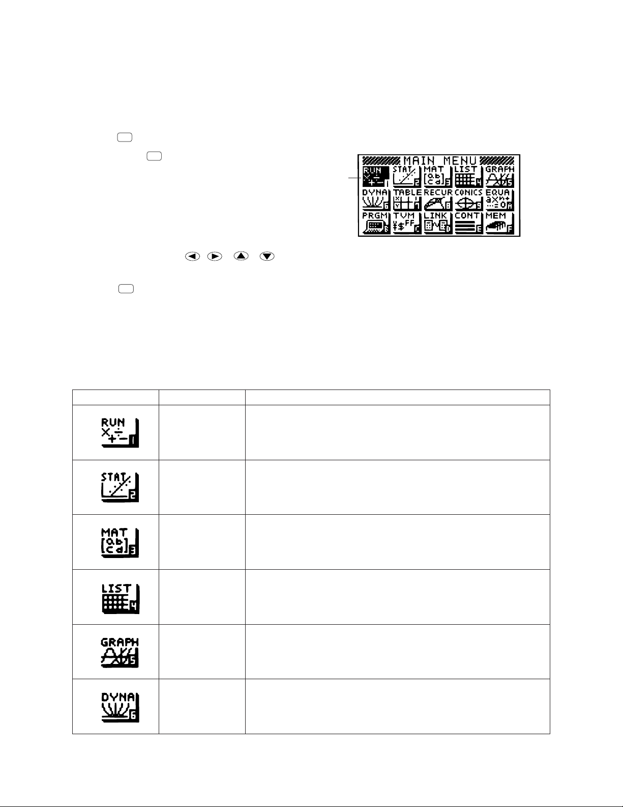
2-1. Modes
• To select an icon
1. Press
MENU
to display the Main Menu.
MENU
Currently selected icon
2. Use the cursor keys ( , , , ) to move the highlighting to the icon you want.
3. Press
EXE
to display the initial screen of the mode whose icon you selected.
• You can also enter a mode without highlighting an icon in the Main Menu by inputting the number or letter
marked in the lower right corner of the icon.
• Use only the procedures described above to enter a mode. If you use any other procedure, you may end
up in a mode that is different than the one you thought you selected.
The following explains the meaning of each icon.
Icon Mode Name Description
RUN Use this mode for arithmetic calculations and function calculations,
and for calculations involving binary, octal, decimal and hexadecimal values.
STATistics Use this mode to perform single-variable (standard deviation) and
paired-variable (regression) statistical calculations, to perform tests,
to analyze data and to draw statistical graphs.
MATrix Use this mode for storing and editing matrices.
LIST Use this mode for storing and editing numeric data.
GRAPH Use this mode to store graph functions and to draw graphs using the
functions.
DYNAmic graph Use this mode to store graph functions and to draw multiple versions
of a graph by changing the values assigned to the variables in a
function.
— 4 —
Page 5
Icon Mode Name Description
TABLE Use this mode to store functions, to generate a numeric table of
different solutions as the values assigned to variables in a function
change, and to draw graphs.
RECURsion Use this mode to store recursion formulas, to generate a numeric
table of different solutions as the values assigned to variables in a
function change, and to draw graphs.
CONICS Use this mode to draw graphs of implicit functions.
EQUAtion Use this mode to solve linear equations with two through six
unknowns, quadratic equations, and cubic equations.
PRoGraM Use this mode to store programs in the program area and to run
programs.
Time Value of Use this mode to perform financial calculations and to draw cash flow
Money and other types of graphs.
LINK Use this mode to transfer memory contents or back-up data to
another unit.
CONTrast Use this mode to adjust the color contrast of the display.
MEMory Use this mode to check how much memory is used and remaining,
to delete data from memory, and to initialize (reset) the calculator.
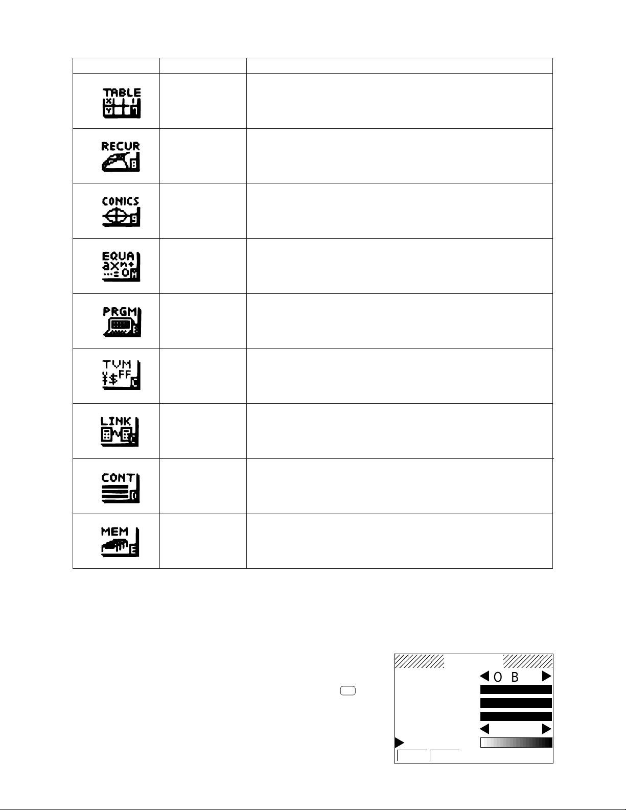
2-2. Color Contrast Adjustment
Adjust the color whenever objects on the display appear dim or difficult to see. There are two different settings
you can make to get color the way you want it.
• Color contrast
• Tint adjustment for each color
• To display the color adjustment screen
COLOR
O B G
Highlight the CONT icon in the Main Menu and then press
• {INIT}/{IN•A} ... {initialize highlighted color}/{initialize all colors}
EXE
.
ORANGE
BLUE
GREEN
Use the following procedures while the color adjustment screen is on
the display to adjust the color contrast and tint settings.
CONTRAST
– +
INIT IN·A
— 5 —
Page 6
• To adjust the color contrast
1. Use the cursor and keys to move the pointer so it is next to CONTRAST.
2. Press the cursor key to make the display darker and the cursor key to make it lighter. Holding
down either key changes the setting at high speed.
• To adjust the color tint
1. Use the cursor and keys to move the pointer so it is next to the color (ORANGE, BLUE, GREEN)
whose tint you want to adjust.
2. Press the cursor key to give the color greener tint and the cursor key to give it an orange tint. Holding
down either key changes the setting at high speed.
• To exit the color adjustment screen
Press
MENU
to return to the Main Menu.
• It is recommended that you always adjust the CONTRAST setting first, and then adjust the tint settings
for individual colors.
• You can change the CONTRAST setting at any time without displaying the color adjustment screen.
Simply press
SHIFT
and then or to change the setting. Press
SHIFT
once again after get the display
looking the way you want.
2-3. Power Supply
This unit is powered by four AAA-size (LR03(AM4) or R03(UM-4)) batteries. In addition, it uses a single
CR2032 lithium battery as a back up power supply for the memory.
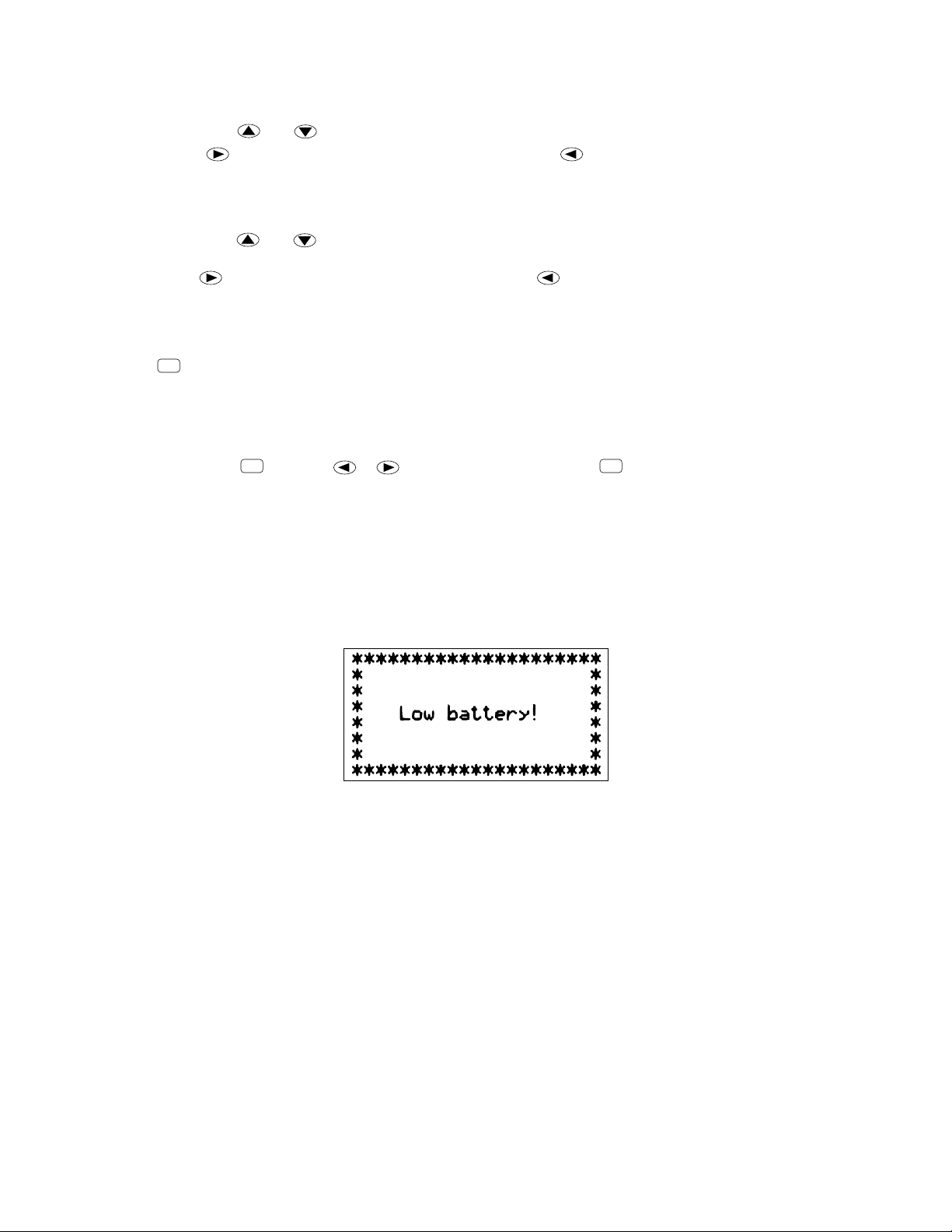
If the following message appears on the display, immediately stop using the calculator and replace batteries.
If you try to continue using the calculator, it will automatically turn power off, in order to protect memory
contents. You will not be able to turn power back on until you replace batteries.
Be sure to replace the main batteries at least once every two years, no matter how much you use the calculator
during that time.
Warning!
If you remove both the main power supply and the memory back up batteries at the same time, all memory
contents will be erased. If you do remove both batteries, correctly reload them and then perform the reset
operation.
Replacing Batteries
Precautions:
Incorrectly using batteries can cause them to burst or leak, possibly damaging the interior of the unit. Note the
following precautions:
— 6 —
Page 7
AC/ON
• Be sure that the positive + and negative - poles of each battery are facing
in the proper directions.
• Never mix batteries of different types.
• Never mix old batteries and new ones.
• Never leave dead batteries in the battery compartment.
• Remove the batteries if you do not plan to use the unit for long periods.
• Never try to recharge the batteries supplied with the unit.
• Do not expose batteries to direct heat, let them become shorted, or try to
take them apart.
(Should a battery leak, clean out the battery compartment of the unit
immediately, taking care to avoid letting the battery fluid come into direct contact with your skin.)
Keep batteries out of the reach of small children. If swallowed, consult with a physician immediately.
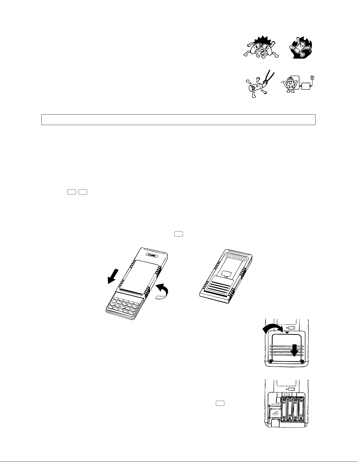
• To replace the main power supply batteries
* Never remove the main power supply and the memory back up batteries from the unit at the same time.
* Never replace the main power supply battery compartment cover or turn the calculator on while the main
power supply batteries are removed from the calculator or not loaded correctly. Doing so can cause
memory data to be deleted and malfunction of the calculator. If mishandling of batteries causes such
problems, correctly load batteries and then perform the RESET operation to resume normal operation.
* Be sure to replace all four batteries with new ones.
SHIFT
1. Press
OFF
to turn the calculator off.
Warning!
* Be sure to turn the unit off before replacing batteries. Replacing batteries with power on will cause data
in memory to be deleted.
2. Making sure that you do not accidently press the
AC/ON
key, slide the case onto the calculator and then turn
the calculator over.
3. Remove the back cover from the calculator by pressing it in the direction
indicated by arrow 1, and then sliding it in the direction indicated by arrow 2.
1
P
2
4. Remove the four old batteries.
5. Load a new set of four batteries, making sure that their positive + and negative
- ends are facing in the proper directions.
6. Replace the back cover.
7. Turn the calculator front side up and slide off its case. Next press
power.
— 7 —
P
MAIN
to turn on
Page 8
• Power supplied by memory back up battery while the main power supply batteries are removed for
replacement retains memory contents.
• Do not leave the unit without main power supply batteries loaded for long periods. Doing so can cause
deletion of data stored in memory.
• If the figures on the display appear too light and hard to see after you turn on power, adjust the tint.
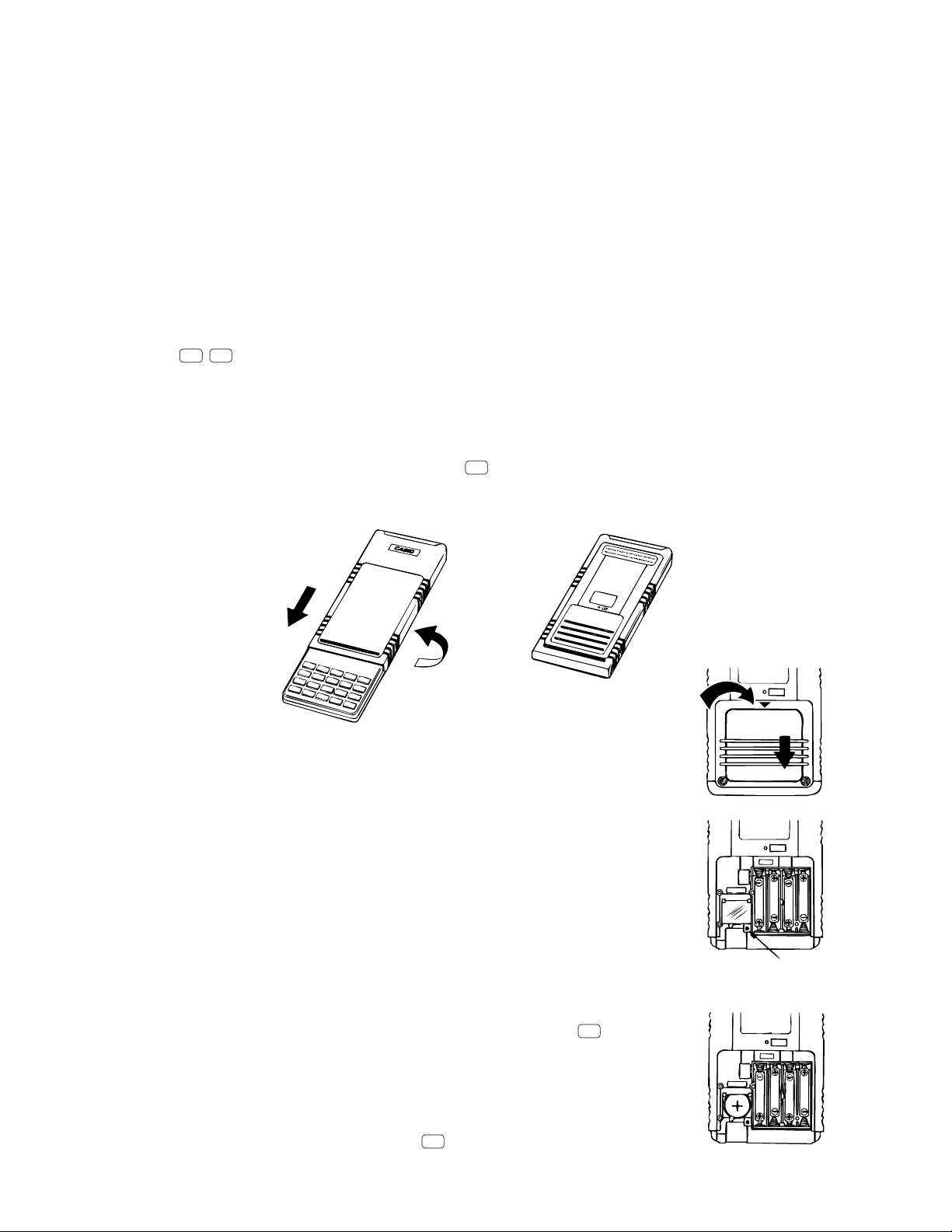
• To replace the memory back up battery
* Before replacing the memory back up battery, turn on the unit and check to see if the “Low battery!”
message appears on the display. If it does, replace the main power supply batteries before replacing the
back up power supply battery.
* Never remove the main power supply and the memory back up batteries from the unit at the same time.
* Be sure to replace the back up power supply battery at least once 2 years, regardless of how much you
use the unit during that time. Failure to do so can cause data in memory to be deleted.
SHIFT
1. Press
OFF
to turn the calculator off.
Warning!
* Be sure to turn the unit off before replacing batteries. Replacing batteries with power on will cause data
in memory to be deleted.
2. Making sure that you do not accidently press the
AC/ON
key, slide the case onto the calculator and then turn
the calculator over.
3. Remove the back cover from the calculator by pressing it in the direction indicated
by arrow 1, and then sliding it in the direction indicated by arrow 2.
4. Remove screw A on the back of the calculator, and remove the back up battery
compartment cover.
5. Remove the old battery.
P
1
2
P
MAIN
6. Wipe off the surfaces of a new battery with a soft, dry cloth. Load it into the
calculator so that its positive + side is facing up.
7. Install the memory protection battery cover onto the calculator and secure it in
place with the screw. Next, replace the back cover.
8. Turn the calculator front side up and slide off its case. Next press
AC/ON
to turn on
power.
About the Auto Power Off Function
The calculator turns power off automatically if you do not perform any key operation
for about 6 minutes. To restore power, press
AC/ON
.
— 8 —
A
P
MAIN
Page 9
EXE
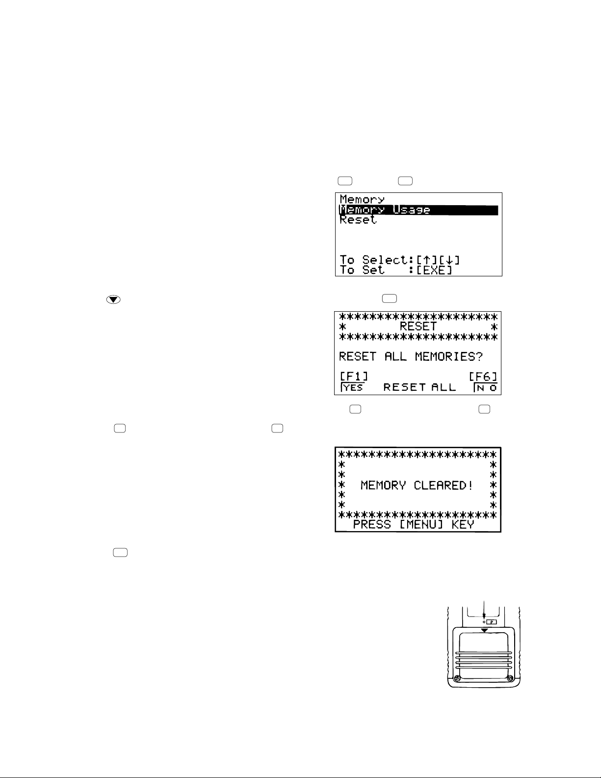
3. RESET OPERATION
Warning!
The procedure described here clears all memory contents. Never perform this operation unless you want to
totally clear the memory of the calculator. If you need the data currently stored in memory, be sure to write
it down somewhere before performing the RESET operation.
• To reset the calculator
1. Highlight the MEM icon on the main menu and then press
EXE
, or press
tan
F
.
2. Use to move the highlighting down to “RESET” and then press
F1 F6
3. Press
4. Press
F1
(YES) to reset the calculator or
MENU
.
F6
(NO) to abort the operation without resetting anything.
.
• If the display appears too dark or dim after you reset the calculator, adjust the tint.
• If the calculator stops operating correctly for some reason, use a thin, pointed
object to press the P button on the back of the calculator. This should make the
RESET screen appear on the display. Perform the procedure to complete the
RESET operation.
• Pressing the P button while an internal calculation is being performed will cause
all data in memory to be deleted.
P button
— 9 —
Page 10
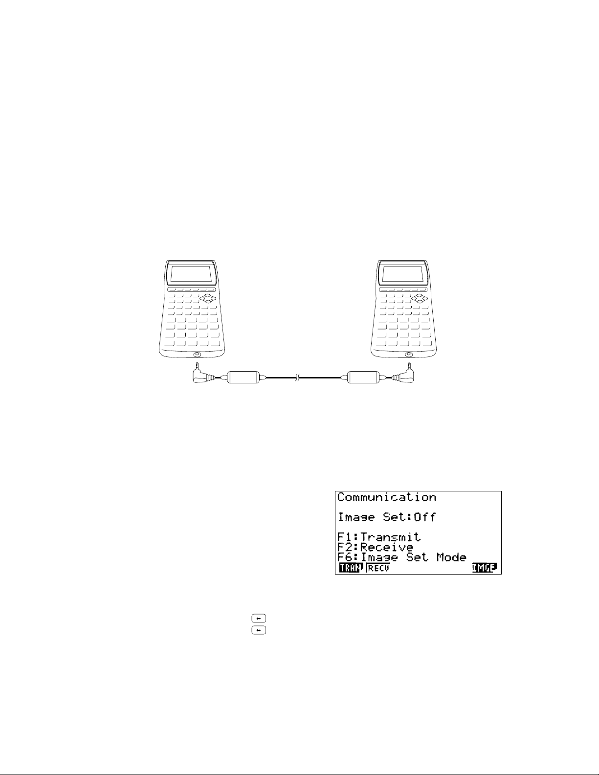
4. DATA COMMUNICATIONS
4-1. Connecting Two Units
The following procedure describes how to connect two units with an optional SB-62 connecting cable for
transfer of programs between them.
To connect two units
1. Check to make sure that the power of both units is off.
2. Remove the covers from the connectors of the two units.
• Be sure you keep the connector covers in a safe place so you can replace them after you finish your data
communications.
3. Connect the two units using the SB-62 cable.
SB-62 cable
• Keep the connectors covered when you are not using them.
4-2. Before Starting Data Communications
In the Main Menu, select the LINK icon and enter the LINK Mode. The following data communication main
menu appears on the display. (Select the LINK icon, then press EXE button.)
Image Set:............Indicates the status of the graphic image send features.
Off: Graphic images not sent.
Monochrome: Pressing
Color: Pressing
•{TRAN}/{RECV} ........ Menu of {send settings}/{receive settings}
•{IMGE} .........{menu of graphic image transfer settings}
sends graphic images in monochrome.
F D
sends graphic images in color.
F D
Communications parameters are fixed at the following settings.
• Speed (BPS): 9600 bits per second
• Parity (PARITY): NONE
— 10 —
Page 11

4-3. Performing Data Transfer Operation
Connect the two units and then perform the following procedures.
Receiving unit
To set up the calculator to receive data, press
displayed.
The calculator enters a data receive standby mode and waits for data to arrive. Actual data receive starts as
soon as data is sent from the sending unit.
Sending unit
To set up the calculator to send data, press
displayed.
F2
(RECV) while the data communication Main Menu is
F1
(TRAN) while the data communication Main Menu is
Press the function key that corresponds to the type of data you want to send.
•{SEL}.......{selects data items and sends them}
•{CRNT}....{selects data items from among previously selected data items and sends them}
•{BACK} ...{all memory contents, including mode settings}
• To send selected data items
Press
F1
(SEL) or F2(CRNT) to display a data item selection screen.
Data items
• {SEL} .......{selects data item where cursor is located}
• {TRAN}....{sends selected data items}
Use the and cursor keys to move the cursor to the data item you want to select and press
to select it. Currently selected data items are marked with “ ”. Pressing
data items.
• To deselect a data item, move the cursor to it and press
▲
F1
(SEL) again.
F6
(TRAN) sends all the selected
F1
(SEL)
Only items that contain data appear on the data item selection screen. If there are too many data items to fit
on a single screen, the list scrolls when you move the cursor to the bottom line of the items on the screen.
The following are the types of data items that can be sent.
— 11 —
Page 12
Data Item
Program
Mat n
List n
File n
Y=Data
Contents
Program contents
Matrix memory (A to Z) contents
List memory (1 to 6) contents
List file memory (1 to 6) contents
Graph expressions, graph write/non-write
Overwrite
Check*
Yes
Yes
Yes
Yes
No
Password
1
Check*
Yes
2
status, View Window contents, zoom factors
G-Mem n
V-Win n
Picture n
DynaMem
Equation
Variable
F-Mem
Graph memory (1 to 6) contents
View Window memory contents
Picture (graph) memory (1 to 6) data
Dynamic Graph functions
Equation calculation coefficient values
Variable assignments
Function memory (1 to 6) contents
Yes
No
No
Yes
No
No
No
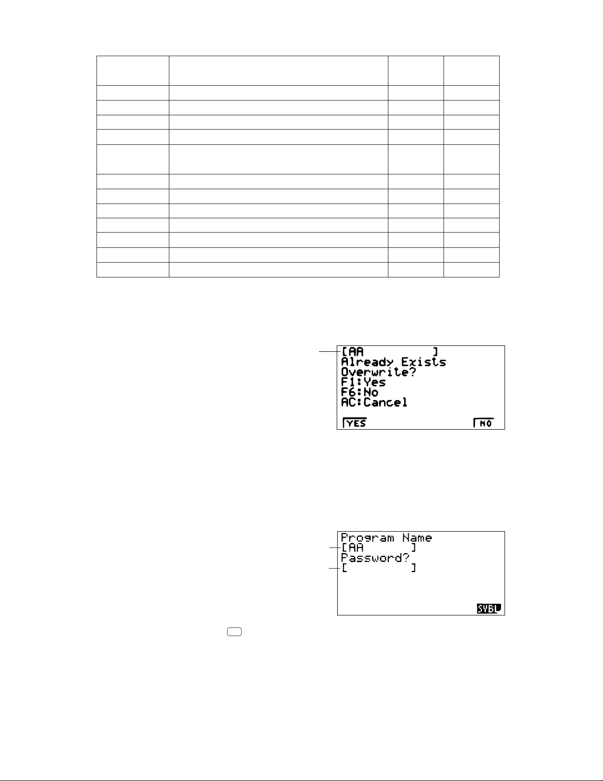
*1No overwrite check: If the receiving unit already contains the same type of data, the existing data is
overwritten with the new data.
With overwrite check:If the receiving unit already contains the same type of data, a message appears
to ask if the existing data should be overwritten with the new data.
Data item name
• {YES} ......{replaces the receiving unit's existing data with the new data}
• {NO} ........{skips to next data item}
*2With password check: If a file is password protected, a message appears asking for input of the
password.
Name of password protected file
• {SYBL} ....{symbol input}
After inputting the password, press
Password input field
EXE
.
— 12 —
Page 13
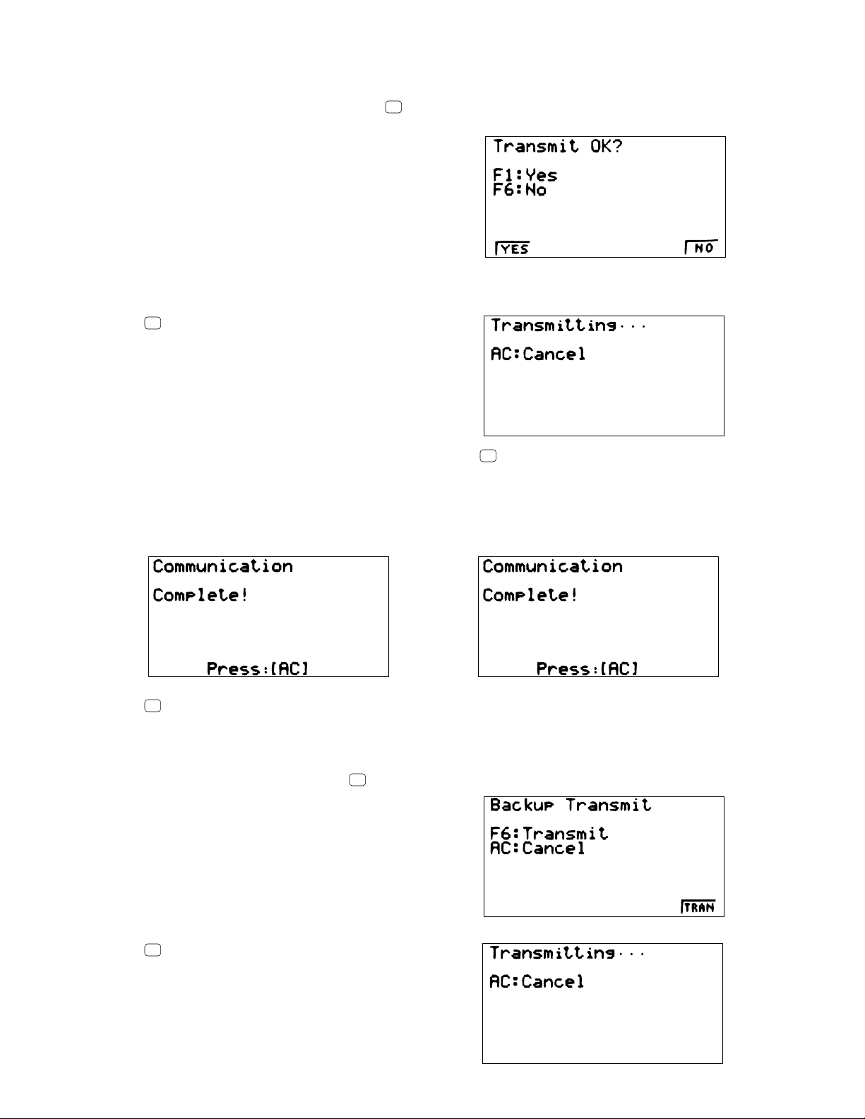
• To execute a send operation
After selecting the data items to send, press
execute the send operation.
• {YES}.....{sends data}
• {NO}.......{returns to data selection screen}
F6
(TRAN). A message appears to confirm that you want to
Press
• You can interrupt a data operation at any time by pressing
F1
(YES) to send the data.
AC
.
The following shows what the displays of the sending and receiving units look like after the data communication
operation is complete.
Sending Unit Receiving Unit
Press
AC
to return to the data communication Main Menu.
• To send backup data
This operation allows you to send all memory contents, including mode settings. While the send data type
selection menu is on the screen, press
Press
F6
(TRAN) to start the send operation.
F6
(BACK), and the back up send menu shown below appears.
— 13 —
Page 14

The following shows what the displays of the sending and receiving units look like after the data communication
operation is complete.
Sending Unit Receiving Unit
Press
AC
to return to the data communication Main Menu.
• Data can become corrupted, necessitating a RESET of the receiving unit, should the connecting cable
become disconnected during data transfer. Make sure that the cable is securely connected to both units
before performing any data communication operation.
4-4. To Send the Screen
The following procedure sends a bit mapped screen shot of the display to a connected computer.
1. Connect the unit to a personal computer or to a CASIO Label Printer.
2. In the data communication main menu, press
• {OFF} .......{graphic images not sent}
• {MONO}/{COLR}.....{monochrome}/{color} bitmap
3. Press a function key to specify either “Monochrome” or “Color” for the Image Set Mode.
F6
(IMGE), and the following display appears.
4. Display the screen you want to send.
5. Set up the personal computer or Label Printer to receive data. When the other unit is ready to receive,
press
to start the second operation.
F D
• Selecting “Monochrome” for Image Set allows data to be sent to any CASIO Label Printer equipped with
data communications capabilities.
Selecting “Color” allows data to be sent to Color Label Printer models only.
You cannot send the following types of screens to a computer.
• The screen that appears while a data communication operation is in progress.
• A screen that appears while a calculation is in progress.
• The screen that appears following the reset operation.
• The low battery message.
• The flashing cursor is not included in the screen image that is sent from the unit.
• If you send a screen shot of any of the screens that appear during the data send operation, you will not
be able to then use the sent screen to proceed with the data send operation. You must exit the data send
operation that produced the screen you sent and restart the send operation before you can send
additional data.
• You cannot use 6 mm wide tape to print a screen shot of a graph.
— 14 —
Page 15

4-5. Data Communication Precautions
AC
AC
Note the following precautions whenever you perform data communications.
• An error occurs whenever you try to send data to a receiving unit that is not yet standing by to receive data.
When this happens, press
data.
• An error occurs whenever the receiving unit does not receive any data approximately six minutes after it
is set up to receive data. When this happens, press
• An error occurs during data communications if the cable becomes disconnected, if the parameters of the
two units do not match, or if any other communications problem occurs. When this happens, press
clear the error and correct the problem before trying data communications again. If data communications
are interrupted by
AC
key operation or an error, any data successfully received up the interruption will be
in the memory of the receiving unit.
• An error occurs if the receiving unit memory becomes full during data communications. When this happens,
press
AC
to clear the error and delete unneeded data from the receiving unit to make room for the new
data, and then try again.
• To send picture (graph) memory data, the receiving unit need 1-kbyte of memory for use as a work area
in addition to the data being received.
to clear the error and try again,after setting up the receiving unit to receive
to clear the error.
AC
to
— 15 —
Page 16

ZX935 Ver.X TEST MODE
1. Cnt
2. LCD
3. KEY
4. DET
5. TRS
6. ROM
7. RAM
8. CYC
0. Rst
✽✽✽✽✽✽✽✽✽✽✽✽✽✽✽✽✽✽✽✽
✽
✽✽✽✽✽✽✽✽✽✽✽✽✽✽✽✽✽✽✽✽
✽
MEMORY CLEARED!
PRESS [MENU] KEY
+–
ORANGE
BLUE
GREEN
CONTRAST
COLOR
O B G
INIT
IN•A
ZX935 Ver.X TEST MODE
1. Cnt
2. LCD
3. KEY
4. DET
5. TRS
6. ROM
7. RAM
8. CYC
0. Rst
5. OPERATION CHECK
❋ Performing this operation check, the data stored in this calculator deleted. If you want not to delete these
data, save these data to another CFX-9850G PLUS.
STEP
1
2
3
4
5
OPERATION
Press P button on the back of
the unit using any thin and pointed
object.
Press F1button.
Press
Press
SHIFT
AC/ON
ingF6 and
Press1, then
AC/ON
, then
button.
button while press-
ab/c
buttons.
EXE
button.
DISPLAY
✽✽✽✽✽✽✽✽✽✽✽✽✽✽✽✽✽✽✽✽
✽
RESET
✽✽✽✽✽✽✽✽✽✽✽✽✽✽✽✽✽✽✽✽
RESET ALL MEMORIES?
[F1] [F6]
RESET ALLYES NO
OFF (No display)
NOTE
Reset
✽
TEST mode menu
The contrast is
changed automatically.
Min→Max→default
EXIT
EXE
EXE
EXE
EXE
EXE
EXE
button.
button.
button.
button.
button.
button.
button.
Press
6
7
Press 2 button.
8
Press
9
Press
10
Press
11
Press
12
Press
13
Press
TEST mode menu
Frame is displayed
No color, no display
All orange dots are displayed
All green dots are displayed
All blue dots are displayed
Checkers are displayed
Reverse checkers are diaplayed
— 16 —
Check for display
Check for display
Check for display
Check for display
Check for display
Page 17

STEP
ZX935 Ver.X TEST MODE
1. Cnt
2. LCD
3. KEY
4. DET
5. TRS
6. ROM
7. RAM
8. CYC
0. Rst
ZX935 Ver.X TEST MODE
1. Cnt
2. LCD
3. KEY
4. DET
5. TRS
6. ROM
7. RAM
8. CYC
0. Rst
ZX935 Ver.X TEST MODE
1. Cnt
2. LCD
3. KEY
4. DET
5. TRS
6. ROM
7. RAM
8. CYC
0. Rst
OPERATION
DISPLAY
NOTE
Press
14
Press
15
Press
16
Press 3 button.
17
EXE
EXE
EXE
button.
button.
button.
Blue
No color
No color
Blue
Orange
Green
Trace
Orange
Green
Check four colors.
If the colors do not
appear accurately,
perform the adjustment mentioned in
page 5.
Check four colors
TEST mode menu
Check for keys
Press
18
Press .....
19
Press 6button.
20
Press
21
Press7button.
22
F1 F2
EXE
EXE
buttons.
button.
F3
..... buttons.
Zoom, V-Window, Sketch
ROMSIZE 8M bits
ROM OK
checksum=
RAMSIZE 32K byte
RAM OK
RAMaddress
RAMwrite
RAMread
— 17 —
Check for keys.
To push the key
sequentially that is
being appeared in
the display.
TEST mode menu
ROM check
xxxxxxxx
TEST mode menu
RAM check
7FFF
AA
AA
Page 18

STEP
✽✽✽✽✽✽✽✽✽✽✽✽✽✽✽✽✽✽✽✽
✽
✽✽✽✽✽✽✽✽✽✽✽✽✽✽✽✽✽✽✽✽
✽
MEMORY CLEARED!
PRESS [MENU] KEY
OPERATION
DISPLAY
NOTE
23
24
Press
Press
EXE
SHIFT
button.
, then
AC/ON
button.
OFF (No display)
Reset
End
— 18 —
Page 19

ZX935 TEST MODE
1. Cnt
2. LCD
3. KEY
4. DET
5. TRS
6. ROM
7. RAM
8. CYC
0. Rst
ZX935 TEST MODE
1. Cnt
2. LCD
3. KEY
4. DET
5. TRS
6. ROM
7. RAM
8. CYC
0. Rst
6. DATA TRANSFER CHECK
Turn off both units (A and B unit), then connect them using the cable SB-60 or SB-62. Perform STEP 1 ~ 4
described in 5. OPERATION CHECK before this check.
STEP
STEP 4
of
5.OPERATION
CHECK
1
2
3
4
5
A unit
OPERATION
Press
AC/ON
button
while pressing
F6
and
ab/c
but-
tons.
Press5button.
Press1button.
Press1button.
Press
EXE
button.
DISPLAY
ZX935 TEST MODE
1. Cnt
2. LCD
3. KEY
4. DET
5. TRS
6. ROM
7. RAM
8. CYC
0. Rst
TRANSMIT Check
1. COM Check
2.
VCCI Spec Test
0. Self
1. Send
2. Receive
SENDING
COM END
0. Self
1. Send
2. Receive
B unit
OPERATION
Press
AC/ON
button
while pressing
F6
and
ab/c
but-
tons.
Press5button.
Press1button.
Press 2 button.
Press
EXE
button.
DISPLAY
TRANSMIT Check
1. COM Check
2.
VCCI Spec Test
0. Self
1. Send
2. Receive
WAITING
RECEIVING
COM OK
0. Self
1. Send
2. Receive
NOTE
TEST mode
menu
Check for
sending and
receptivity
6
7
8
9
10
Press 2 button.
Press
Press
EXE
AC/ON
button.
button.
Take the steps as
same as the end of
5. OPERATION
CHECK to end this
check.
WAITING
RECEIVING
COM OK
0. Self
1. Send
2. Receive
ZX935 TEST MODE
1. Cnt
2. LCD
3. KEY
4. DET
5. TRS
6. ROM
7. RAM
8. CYC
0. Rst
Press1button.
Press
Press
EXE
AC/ON
button.
button.
Take the steps as
same as the end of
5. OPERATION
CHECK to end this
check.
— 19 —
SENDING
COM END
0. Self
1. Send
2. Receive
Check for
sending and
receptivity
TEST mode
menu
End
Page 20

7. PIN FUNCTION
CPU HCD62121A03 (HC-3017) : COB
NOTE: The CPU is bonding on the PCB. If the CPU is defective, replace the PCB ass'y because
the CPU cannot be replaced.
Pin No. Pin Name Input/Output Function
1 ~ 14 KO14 ~ KO1 O Key common signal
15 ~ 22 KI8 ~ KI1 I Key input signal
23 BUFON O Chip select for RAM
24 IT2 I Interrupt input
25 IT0 I Interrupt input
26 ~ 46 AO20 ~ AO0 O Address bus
47 ~ 54 IO0 ~ IO7 I / O Data bus
55 OEBO O Output enable signal for RAM
56 WEBO O Write enable signal for RAM
64 CS3BO O Chip selecting signals
69 ~ 72 OPT3 ~ OPT0 O Changeover signal
73 PORT7 I Receiving terminal for data communication
74 PORT6 I Receiving terminal for data communication
75 PORT5 O Transmitting terminal for data communication
76 PORT4 O Transmitting terminal for data communication
80 PORT0 I Low battery message for back-up battery (2.6 V)
81 VSS I GND
82 PI I 4.3 MHz clock input
83 PO O 4.3 MHz clock output
84 VDD I +6 V source
85 XO O Clock output
86 XI I Clock input
87 VCC I +6 V source
88 VREG2 O Voltage for main switch detection
89, 90 TS1, TS2 — Test terminals of factory purpose only
91 VSSR I GND
94 VSS I GND
96 ITOFF I Switching terminal from main switch
97 TEMU — Test terminals of factory purpose only
98 SW I Receiving terminal for reset switch
99 VDB I +3 V source
100 VREG1 — Test terminals of factory purpose only
101 VREG4 O +3 V source for ROM
102 VREG5 — Test terminals of factory purpose only
103 VDT1I I Forced power off detecting terminal (2.3 V)
104 VDT2I I Low battery message for main battery (2.5 V)
105 VREG3 — +3 V source for RAM
— 20 —
Page 21

8. TROUBLESHOOTING
SYMPTOM CAUSE SOLUTION
Intermittent display
No display at all
Erratic display
Dirt or poor contact on battery
Poor contact on power switch
Poor connection on PC joiner
Poor soldering on LSI, capacitor, or resistor
Weak battery
Dirt or poor contact on battery
Poor contact on power switch
Poor connection on PC joiner
Defective LSI, capacitor, or resistor
Poor contact between LCD and PCB
Poor soldering on LSI
Clean or adjust pressure of
contact
Clean or replace power
switch
Resolder or replace
Resolder
Replace battery
Clean or adjust pressure of
contact
Clean or replace power
switch
Resolder or replace
Replace
Replace the heat seal
Resolder or replace display
PCB ass'y
Certain key does not
function
All keys do not function
Heavy key motion
Dirt on key contact
Heavy key motion
Poor soldering on LSI
Defective LSI, capacitor, or resistor
Constant contact is made on a certain key
Defective LSI, capacitor, or resistor
Dirt or scratch on the key
Clean or replace contact
Clean or replace the key
Resolder
Replace
Separate the contact
Replace
Clean or replace the key
— 21 —
Page 22

About 3 seconds later
9. OPERATION PROBLEMS
If you keep having problems when you are trying to perform operations, try the following before assuming that
there is something wrong with the calculator.
• Get the Calculator Back to its Original Mode Settings
1. In the Main Menu, select the RUN icon and press
SHIFT
2. Press
3. Highlight "Angle" and press
4. Highlight "Display" and press
SET UP
to display the set up screen.
F2
(Rad).
F3
(Norm) to select the exponential display range (Norm 1 or Norm 2) that
EXE
.
you want to use.
5. Now enter the correct mode and perform your calculation again, monitoring the results on the display.
• In Case of Hang Up
• Should the unit hang up and stop responding to input from the keyboard, press the P button on the back
of the calculator to reset the memory. Note, however, that this clears all the data in calculator memory.
• Low Battery Message
The low battery message apppears whenever you press
AC/ON
to turn power on or
MENU
to display the Main
Menu while the main battery power is below a certain level.
AC/ONorMENU
If you continue using the calculator without replacing batteries, power will automatically turn off to protect
memory contents. Once this happens, you will not be able to turn power back on, and there is the danger that
memory contents will be corrupted or lost entirely.
• You will not be able to perform data communications operations once the low battery message appears.
— 22 —
Page 23

10. ERROR MESSAGE
Message
Syn ERROR
Ma ERROR
Go ERROR
Meaning
1 Calculation formula contains an error.
2 Formula in a program contains an error.
1 Calculation result exceeds calculation
range.
2 Calculation is outside the input range of
a function.
3 Illogical operation (division by zero, etc.)
4 Poor precision in Σ calculation results.
5 Poor precision in differential calculation
results.
6 Poor precision in integration calculation
results.
7 Cannot find results of equation calcula-
tions.
1 No corresponding Lbl n for Goto n.
2 No program stored in program area Prog
“file name”.
Countermeasure
1 Use or to display the point
where the error was generated and correct it.
2 Use or to display the point
where the error was generated and then
correct the program.
1234
Check the input numeric value and correct it.
When using memories, check that the
numeric values stored in memories are
correct.
5 Try using a smaller value for ∆x (x incre-
ment/decrement).
6 Try changing the tolerance “tol” when
using Gauss-Kronrod Rule or the number of divisions “n” when using Simpson’s
Rule to another value.
7 Check the coefficients of the equation.
1 Correctly input a Lbl n to correspond to
the Goto n, or delete the Goto n if not
required.
2 Store a program in program area Prog
“file name”, or delete the Prog “file name”
if not required.
Ne ERROR
Stk ERROR
• Nesting of subroutines by Prog “file name”
exceeds 10 levels.
• Execution of calculations that exceed the
capacity of the stack for numeric values or
stack for commands.
— 23 —
• Ensure that Prog “file name” is not used to
return from subroutines to main routine. If
used, delete any unnecessary Prog “file
name”.
• Trace the subroutine jump destinations
and ensure that no jumps are made back
to the original program area. Ensure that
returns are made correctly.
• Simplify the formulas to keep stacks within
10 levels for the numeric values and 26
levels for the commands.
• Divide the formula into two or more parts.
Page 24

Message
Meaning
Countermeasure
Mem ERROR
Arg ERROR
Dim ERROR
• Not enough memory to input a function
into function memory.
• Not enough memory to create a matrix
using the specified dimension.
• Not enough memory to hold matrix calculation result.
• Not enough memory to store data in list
function.
• Not enough memory to input coefficient
for equation.
• Not enough memory to hold equation calculation result.
• Not enough memory to hold function input
in the Graph Mode for graph drawing.
• Not enough memory to hold function input
in the DYNA Mode for graph drawing.
• Not enough memory to hold function or
recursion input.
• Incorrect argument specification for a
command that requires an argument.
• Illegal dimension or list used during matrix
calculations.
• Keep the number of variables you use for
the operation within the number of variables currently available.
• Simplify the data you are trying to store to
keep it within the available memory capacity.
• Delete no longer needed data to make
room for the new data.
• Correct the argument.
• Lbl n, Goto n: n = integer from 0 through 9.
• Check matrix or list dimension.
Com ERROR
TRANSMIT
ERROR!
RECEIVE
ERROR!
MEMORY
FULL!
• Problem with cable connection or parameter setting during program data communications.
• Problem with cable connection or parameter setting during data communications.
• Problem with cable connection or parameter setting during data communications.
• Memory of receiving unit became full
during program data communications.
• Check cable connection.
• Check cable connection.
• Check cable connection.
• Delete some data stored in the receiving
unit and try again.
— 24 —
Page 25

11. SCHEMATIC DIAGRAMS
Main Block 1
— 25 —
ROM
Page 26

Main Block 2
— 26 —
Page 27

Key Block
To Main Block 1
— 27 —
Page 28

12. PARTS LIST
N Item Code No. Parts Name Specification Q R
ZX933-1 ASS'Y
LSI3 2012 3192 LSI TC55257DFL-7085V 1 B
LSI4 2012 3185 LSI LC3564SM-70 1 B
N LSI2 2012 5645 LSI MBM29LV800B-Z935 1 B
Q2 2250 1281 Chip transistor 2SA1179M5, M6, M7-TB 1 C
IC1 2114 4683 CMOS-IC TC74HC4066AFS(EL) 1 C
IC2 2105 2737 CMOS-IC RH5RL50AA-T1 1 C
IC6 2105 2968 CMOS-IC RH5RE43AA-T1 1 C
THR1 2755 0147 Thermister 104HT 1 X
VR1 3122 3227 Chip variable resister CVR-32A-503SX2 1 X
X1 2590 1967 Ceramic oscillator CSTC4.30MG-TC 1 C
ZX933-2 ASS'Y
1 6416 9441 Battery spring A-Z933 A441557A-1 1 X
2 6416 9450 Battery spring B-Z933 A441558-1 1 X
3 3501 6538 Mini jack HSJ1169-012010 1 C
Q1 2259 0959 Chip digital transistor DTC114YKT-146 1 C
LCD UNIT
4 3335 6216 LCD CD1052-TS 1 B
5 6416 9370 LCD holder Z933 A341010-1 1 C
6 5610 9050 Heat seal C-Z933 A340956-1 1 B
7 5610 9060 Heat seal S-Z933 A341018-1 1 B
LSI5 6417 3441 COF3015-F1 sub ass'y C340532A*2 1 B
LSI6 6416 3211 COF3016-F1 sub ass'y C340533A*1 1 B
PCB UNIT
N 8 6420 7250 Z933-2 ASS'Y A240572A*2 HK 1 B
N 9 6420 2300 Z933-1 ASS'Y A140379Q*4 HK 1 B
10 6417 3430 LCD UNIT A240603B*2 HK 1 B
11 6408 0210 PC joiner L370 A413642-1 1 B
COMPONENTS
12 6416 9340 Key contact rubber Z933 A240567-1 1 C
N 13 6420 2330 Hard case Z935AE A240568-3 1 C
14 6416 9500 Battery holder A441594-1 1 X
15 6416 9380 Display plate Z933 A341011-1 1 C
16 6390 0432 Cap V332 A310765B-1 1 C
17 6413 5080 Button E-L392 A313257-3 1 C
18 6413 5090 Button F-L392 A313257-4 1 C
N 19 6420 5330 Button B-Z935 A340110-3 1 C
20 6413 6000 Button H-L392 A340256-1 1 C
21 6419 5130 Button A-Z934 A240072-4 1 C
N 22 6420 5310 Button B-Z935 A211316-10 1 C
23 6413 5011 Button C-L392 A340111A-1 1 C
N 24 6420 5340 Button D-Z935 A340123-3 1 C
N 25 6420 5320 Button G-Z935 A313257-8 1 C
N 26 6420 2320 Upper case Z935AE A140373-7 1 X
27 6417 3450 Badge label Z933 A441676-1 1 C
N 28 6420 2340 Battery cover Z935AE A240903-3 1 C
29 6408 0110 Battery spring B-L370 A410113-3 2 X
30 6408 0120 Battery spring L370 A412218-2 1 X
31 6419 9840 Rubber key Z934 A341594-1 1 C
N 32 6420 2350 Lock spring Z935AE A341016-3 1 C
N 33 6420 2362 Lower case Z935AY A140374B-8 1 X
34 6417 3520 Spring H-Z933 A441675-1 1 C
Parts prices will be informed separately by Parts Price List.
R – A :
Notes: N – New parts Essential
Q – Quantity used per unit Stock recommended
R – Rank Others
— 28 —
R – A :
B :
B :
C :
C :
X :
X :
No stock recommended
Page 29
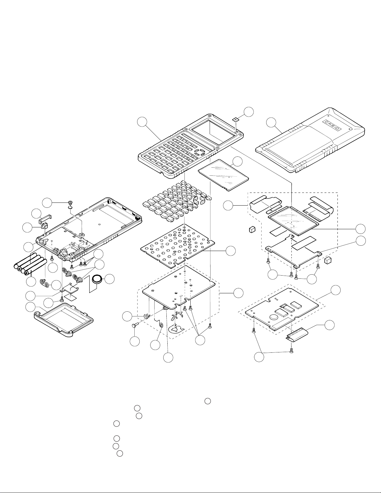
13. EXPLODED VIEW (1/2)
26
27
13
15
32
33
31
34
S2
B2
14
S1
28
DISASSEMBLY
30
S2
29
B1
10
4
5
12
S3
8
S3
9
1
11
16
2
3
S5
S4
1. Remove the hard case C.
2. Remove the battery cover R.
3. Remove the battery holder D, then loosen the screw .
4. Remove the lithium battery .
5. Remove four main batteries .
6. Loosen four screws .
S2
B1
B2
7. Open the lower case W using any opener.
8. Loosen four screws .
9. Loosen two screws .
10. Loosen three screws .
S3
S4
S5
— 29 —
S1
Page 30

23
25
24
22
20
19
21
18
17
4 6
7
LSI6
LSI5
13. EXPLODED VIEW (2/2)
— 30 —
Page 31

MA0500671A
 Loading...