

Page 1
Data Collector
Colector de Datos
Datenerfassungsgerät
Collecteur de Données
User’s Guide
Guía del usuario
Bedienungsanleitung
Mode d’emploi
• Congratulations upon your selection of
the CASIO IT-2000 Data Collector.
• Be sure to familiarize yourself with the
basic operations described in this
manual before actually trying to
operate the Data Collector.
• Enhorabuena por la selección del
colector de datos IT-2000 CASIO.
• Antes de intentar utilizar este colector
de datos, familiarícese con las
operaciones básicas descritas en este
manual.
• Mit dem Datenerfassungsgerät CASIO
IT-2000 haben Sie eine gute Wahl
getroffen.
• Bitte machen Sie sich mit den in
diesem Handbuch beschriebenen
Grundfunktionen vertraut, bevor Sie
beginnen, mit dem
Datenerfassungsgerät zu arbeiten.
789
456
0123
P
• Nous vous remercions d’avoir choisi le
Collecteur de Données Casio IT-2000.
• Veuillez vous familiariser avec les
démarches de base, décrites dans ce
manuel, avant d’essayer d’utiliser le
Collecteur de Données.
Page 2
Safety Precautions
Congratulations upon your selection of this CASIO Product. Be sure to read
the following Safety Precautions before trying to use it for the first time.
Keep this manual in a handy place for future reference.
Markings and Symbols
Danger!
Warning!
Caution!
Marking examples
The following are the meanings of the markings and symbols
used in these Safety Precautions to warn you against the
possibility of personal injury and/or material damage or loss
to you and others. Take a few moments to become familiar
with these markings and symbols so you can avoid future
problems.
This symbol indicates information that, if ignored or
applied incorrectly, creates the danger of death or serious
personal injury.
This symbol indicates information that, if ignored or
applied incorrectly, can create the possibility of death or
serious personal injury.
This symbol indicates information that, if ignored or
applied incorrectly, can create the possibility of personal
injury or material damage.
A triangular shape indicates you should exercise
caution. The symbol shown here indicates you
should take care to avoid breakage.
A circle indicates something you should not do.
This symbol indicates you should not try to
take something apart.
A black circle indicates something you must
do. This symbol indicates you should unplug
something.
E-3
Page 3
Danger!
■ Supplied Lithium-ion Battery Pack
●Never allow the battery pack to become wet with either fresh water or salt
water. Water can create the danger of battery pack heat emission, explosion,
and fire.
●Never use or leave the battery pack next to open flame, near a stove, or any
other area exposed to high heat. Doing so creates the danger of battery
pack heat emission, explosion, and fire.
●Never use the battery pack with any device other than the Data Collector.
Doing so can create the danger of battery pack heat emission, explosion,
and fire.
●Note that the battery pack’s positive (+) and negative (–) terminals must be
oriented correctly when it is loaded into the charger unit or the Data
Collector. Connecting the battery pack with its terminals reversed creates the
danger of battery pack fluid leakage, heat emission, explosion, and fire.
●Never dispose of the battery pack by incinerating it or otherwise expose it to
heat. Doing so creates the danger of battery pack heat emission, explosion,
and fire.
●Never allow the positive (+) and negative (–) terminals of the battery pack to
become connected (shorted) by metal. Doing so creates the danger of
battery pack heat emission, explosion, and fire.
●Never transport or store the battery pack together with a necklace, hair pins
or other metal objects. Doing so can short battery pack terminals, creating
the danger of battery pack heat emission, explosion, and fire. Be sure to
place the battery pack in its case whenever transporting or storing it.
●Never throw the battery pack or otherwise subject it to strong impact. Doing
so creates the danger of battery pack heat emission, explosion, and fire.
●Never pierce the battery pack with nails, hit it with a hammer, or step on it.
Doing so can create the danger of battery pack heat emission, explosion,
and fire.
●Never try to take apart the battery pack or modify it in any way. Doing so
creates the danger of battery pack heat emission, explosion, and fire.
E-4
●Use only the specified charger unit to charge the battery pack. Use of
another type of charger unit creates the danger of battery pack heat
emission, explosion, and fire.
Page 4
Warning!
■ Disassembly and Modification
●Never try to disassemble or modify the Data Collector in any way. High
voltage inside creates the danger of electric shock. There are hot parts
inside the printer. Do not touch these parts with your hands. Doing so can
cause burns.
■ Interior Parts and Components
●Never touch interior high-voltage parts or components. Doing so creates the
danger of electric shock.
●The printer motor and the area around the head become hot. Do not touch
these parts with your hands. Doing so can cause burns.
■ Abnormal Conditions
●Should the Data Collector become hot or start to emit smoke or a strange
odor, immediately turn off the power and contact your original dealer or an
authorized a CASIO service provider. Continued use creates the danger of
fire and electric shock.
■ Foreign Objects
●Should any foreign matter get into the Data Collector, immediately turn off
the power and contact your original dealer or an authorized a CASIO service
provider. Continued use creates the danger of fire and electric shock.
■ Dropping and Damage
●Should you drop the Data Collector and damage it, immediately turn off the
power and contact your original dealer or an authorized a CASIO service
provider. Continued use creates the danger of fire and electric shock.
■ Moisture
●Keep the Data Collector away from vases, planters, cups, glasses and other
containers of liquid. Also keep it away from metal. Water and metal getting
into the Data Collector creates the danger of fire and electric shock.
E-5
Page 5
Warning!
■ Battery Handling
●Never try to take batteries apart, modify them, or allow their positive and
negative poles to be connected (become shorted). Do not expose batteries
to heat, and never throw batteries into fire.
• When you remove the lithium-ion battery from the Data Collector, take
care to keep it in a place where there is no danger of it being accidentally
swallowed. Be especially careful around small children.
●Keep batteries out of the reach of small children. If a battery is accidentally
swallowed, consult a physician immediately.
■ Supplied Lithium-ion Battery Pack
●Never place the battery pack in a microwave oven or any other high-voltage
device. Doing so creates the danger of battery pack heat emission,
explosion, and fire.
●Should the battery pack emit a strange odor or heat, change color or shape,
or exhibit any other abnormal behavior, immediately stop using it. Continued
use creates the danger of battery pack heat emission, explosion, and fire.
●If the battery pack does not achieve full charge after the normal charging
time has passed, stop charging. Continued charging creates the danger of
battery pack heat emission, explosion, and fire.
●Should the battery pack start to leak or emit a strange odor, immediately
move it away from any nearby flame. Leaking battery fluid is combustible,
and exposure to flame creates the danger of explosion and fire.
●Should fluid from the battery pack accidentally get into your eyes, do not rub
them. Immediately rinse your eyes with clean tap water and then consult a
physician immediately.
■ AC Power Supply
●Do not use the Data Collector at a voltage other than the specified voltage of
100V AC. Also, do not connect the Data Collector to a multi-plug power strip.
Doing so creates the danger of fire and electric shock.
●Avoid conditions that can cause damage or breaks in the power cord. Do not
place heavy objects on the power cord and keep it away from sources of
heat. Any of these conditions can damage the power cord, creating the
danger of fire and electric shock.
●Never modify, sharply bend, twist, or pull on the power cord. Doing so
creates the danger of fire and electric shock.
●Use only the specified charger unit DT-9020ADP (sold separately). When
using the I/O box, be sure to use the AC adapter DT-825ADP (sold
separately). Use of another AC adapter model or charger creates the danger
of fire and electric shock.
●Should the power cord become severely damaged (to the point that wires
are exposed or broken), contact your original dealer or a CASIO service
provider about repair or replacement. Use of a damaged electrical cord
creates the danger of fire and electric shock.
E-6
Page 6
■ Foreign Objects
●Take care to ensure that metal or combustible objects are not inserted into
the openings of the Data Collector. Such objects create the danger of fire
and electric shock.
■ Location
●
Do not locate the Data Collector on a surface that is unstable or uneven. Doing so
creates the danger of the Data Collector falling, which can cause personal injury.
●Do not locate the Data Collector in an area subject to large amounts of
humidity or dust. Doing so creates the danger of fire and electric shock.
●
Do not leave the Data Collector for long periods in a car parked in direct sunlight.
■ Heavy Objects
●Never place heavy objects on top of the Data Collector. Doing so creates the
danger of loss of balance and the object falling, which can cause personal
injury.
■ LCD Screen
●Never apply strong pressure to the screen or subject it to strong impact.
Doing so can crack the screen or LCD panel glass, which can cause the
danger of personal injury.
●Should the LCD panel glass break, never touch the liquid inside. Doing so
can cause skin inflammation.
• Should liquid from the LCD panel accidentally get into your mouth,
immediately wash your mouth with water and then consult a physician.
• Should liquid from the LCD panel accidentally get into your eyes or onto
your skin, immediately rinse for at least 15 minutes with clean tap water
and then consult a physician.
Caution!
■ Printer
●Do not touch the gears while they are turning. Doing so can cause injury.
■ Battery Handling
●Misuse of batteries can cause them to leak, which damages and corrodes
the area around the battery, and creates the danger of fire and personal
injury. Be sure to observe the following precautions.
• When loading batteries, make sure that their positive (+) and negative (–)
poles are facing the correct directions.
• Use only battery types that are specified for the Data Collector.
●If you do not plan to use the Data Collector for a long time, protect against
rundown of the lithium backup battery by loading a fully charged lithium-ion
battery pack into the Data Collector. You should also load a fully charged
lithium-ion battery pack into the Data Collector before using it for the first
time following a long period of non-use.
E-7
Page 7
Caution!
■ Lithium-ion Battery Pack
●Never use or leave the battery pack in an area exposed to direct sunlight, in
a car parked in direct sunlight, or any other very hot area. Doing so creates
the danger of heat emission and fire, as well as deterioration of battery pack
performance and shortening of its service life.
●Do not use the battery pack in areas where static electricity is being
generated. Doing so creates the danger of battery pack heat emission,
explosion, and fire.
●Should fluid from the battery pack accidentally get onto clothing or your skin,
immediately rinse it off with clean tap water. Prolonged contact with battery
pack fluid can cause skin irritation.
●Keep the battery pack out of the reach of small children. Do not let small
children remove the battery pack from the charger unit or the Data Collector
while it is powered on.
■ Backup Copies of All Important Data
●Note that CASIO Computer Co., Ltd. shall not be held liable to you or any
third party for any damages or loss caused by deletion or corruption of data
due to use of the Data Collector, malfunction or repair of the Data Collector
or its peripherals, or due to batteries going dead.
●The Data Collector employs electronic memory to store data, which means
that memory contents can be corrupted or deleted if power is interrupted due
to batteries going dead or incorrect battery replacement procedures. Data
cannot be recovered once it is lost or corrupted. Be sure to make backup
copies of all important data. One way to do this is to use the separately sold
I/O box to transfer data to a computer.
■ AC Power Supply
●Keep the power cord away from stoves and other sources of extreme heat.
Heat can melt the covering of the power cord and create the danger of fire
and electric shock.
●Never pull on the power cord when unplugging it. Doing so can damage the
cord and create the danger of fire and electric shock. (Always hold onto the
plug when unplugging it from the wall outlet.)
●Never touch the plug while your hands are wet. Doing so can create the
danger of electric shock.
●Be sure to unplug the power cord from the wall outlet before moving the
Data Collector. Failure to do so can result in damage to the power cord
caused by pulling it, which creates the danger of fire and electric shock.
●Be sure to unplug the power cord from the wall outlet before cleaning the
Data Collector.
●Be sure to turn the power OFF and unplug the power cord after use.
●Unplug the power cord from the wall outlet whenever leaving the Data
Collector unattended for long periods.
E-8
Page 8

GUIDELINES LAID DOWN BY FCC RULES FOR USE OF THIS
UNIT IN THE U.S.A. (not applicable to other areas).
NOTICE
This equipment has been tested and found to comply with the limits for a Class B digital
device, pursuant to Part 15 of the FCC Rules. These limits are designed to provide
reasonable protection against harmful interference in a residential installation. This
equipment generates, uses and can radiate radio frequency energy and, if not installed
and used in accordance with the instructions, may cause harmful interference to radio
communications. However, there is no guarantee that interference will not occur in a
particular installation. If this equipment does cause harmful interference to radio or
television reception, which can be determined by turning the equipment off and on, the
user is encouraged to try to correct the interference by one or more of the following
measures:
• Reorient or relocate the receiving antenna.
• Increase the separation between the equipment and receiver.
• Connect the equipment into an outlet on a circuit different from that to which the
receiver is connected.
• Consult the dealer or an experienced radio/TV technician for help.
Changes or modifications not expressly approved by the party responsible for
compliance could void the user’s authority to operate the equipment.
Proper connectors must be used for connection to host computer and/or peripherals in
order to meet FCC emission limits.
Peripherals and Connectors
FCC WARNING
Desktop computer
Optical Communication Unit (IT-2060IOE)
Lithium ion Battery Pack (DT-9023LI)
Charger (DT-9020ADP-U)
AC adapter for Optical Communication Unit
PC Card (DT-9031BFMC, DT-9033BFMC, DT-9034BFMC)
Bar-code reader (DT-9650BCR)
Connectors
(DT-825ADP-U)
(DT-883RSC, DT-882RSC, DT-887AX, DT-881RSC, DT-888RSC)
Declaration of Conformity
Model Number: IT-2000D33E, IT-2000D53E, IT-2060IOE and DT-825ADP-U
Trade name: CASIO COMPUTER CO., LTD.
Responsible party: CASIO MANUFACTURING CORPORATION
Address: 181 Metro Drive, Suite 400. San Jose, California 95110
Telephone number: 1-888-93-CASIO
This device complies with Part 15 of the FCC Rules. Operation is subject to the
following two conditions: (1) This device may not cause harmful interference, and (2)
this device must accept any interference received, including interference that may cause
undesired operation.
E-9
Page 9

• Information in this manual is subject to change without notice.
• CASIO shall have neither liability nor responsibility to any person or entity with respect to
any loss or damages arising from the information contained in this book.
• This manual does not provide information about programming and downloading. See other
manuals coming with IT-2000 for information about these subjects.
• All efforts were made to create this manual as complete and as accurate as possible but in
case our in user find unclear explanation or errors, we would appreciate remarks and
suggestions communicated by users.
CONTENTS
Safety Precautions.................................................E-3
Introduction ..........................................................E-12
Precautions .........................................................................E-12
IT-2000 Series System Configuration.................E-14
General Guide.......................................................E-17
Installing and Removing Batteries .....................E-19
Main power supply ..............................................................E-19
Backup batteries..................................................................E-21
Position of the Keys.............................................E-23
Position of stroke keys ........................................................E-23
Touch key panel ..................................................................E-24
System Initialization Routine ..............................E-25
Charging the Battery Pack ..................................E-26
To charge the battery pack ..................................................E-26
To charge battery packs using the Charger.........................E-27
Attaching the Neck Strap ....................................E-28
Data Communication ...........................................E-29
Exchanging Data Between Two Data Collectors.................E-29
Exchanging Data with a Personal Computer.......................E-29
Handling the Printer.............................................E-30
Using Roll Paper .................................................................E-30
Using Paper Tape................................................................. E34
E-10
Page 10

CASIO ELECTRONICS CO., LTD.
Unit 6, 1000 North Circular Road
London NW2 7JD, U.K.
IT-2000’s Specifications.......................................E-37
IT-2060IOE Optional Optical
Communication Unit .......................................E-38
General Guide .....................................................................E-38
Connecting the Optical Communication Unit
to a Power Source .........................................................E-40
Daisy Chaining Optical Communication Units .....................E-42
DIP Switch Settings .............................................................E-43
IT-2060IOE Optical Communication Unit Specifications .....E-44
Handling Bar-Code Reader .................................E-45
Connecting the bar-code reader..........................................E-45
Detaching bar-code reader..................................................E-45
Using a bar-code reader......................................................E-45
Bar-Code Reader Specifications .........................................E-49
Using PC Cards ....................................................E-50
To load a memory card into the Data Collector ...................E-50
To remove a card from the Data Collector...........................E-51
Attaching the Screen Protective Cover..............E-52
Drip-Proof Cover ..................................................E-53
Operating Precautions.........................................E-54
Notice ....................................................................E-55
E-11
Page 11
Introduction
In order to maintain and use the Data Collector, keep in mind these precautions.
Precautions
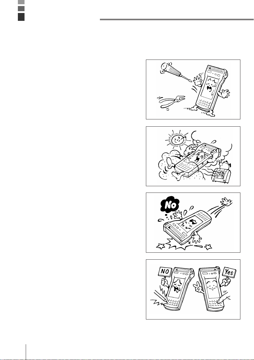
• This product is made of precision parts so do
not try to disassemble by yourself.
• Do not expose the Data Collector to excessive
heat or cold. Do not place it direct sunlight,
dusty or extremely humid areas. The utilization
of the power supply in moisture places is
forbidden. Do not leave the Data Collector on
hot places, such as car trunk or seats.
• Do not expose it to mechanical shocks,
especially during running programs, recording
or booting up because it can cause permanent
loss of data and damage to the LCD.
• Stroke keys must be pressed with care.
Use only the special touch panel pen for
working with the touch panel.
Do not apply excessive force or use sharp
objects for this purpose because in that way
you can damage the touch panel or internal
circuitry.
E-12
Page 12
• Blow off dust with a blower brush or a soft
cloth.
No utilization of liquid- or spray-cleansing
agents is allowed. It may deform the keys or
the body of the Data Collector. The Data
Collector must not come in contact with
chemicals and gasoline.
• Do not place heavy objects on the Data
Collector.
Important! CASIO does not accept any responsibility for possible data loss caused
during, or connected with, usage of the Data Collector.
E-13
Page 13
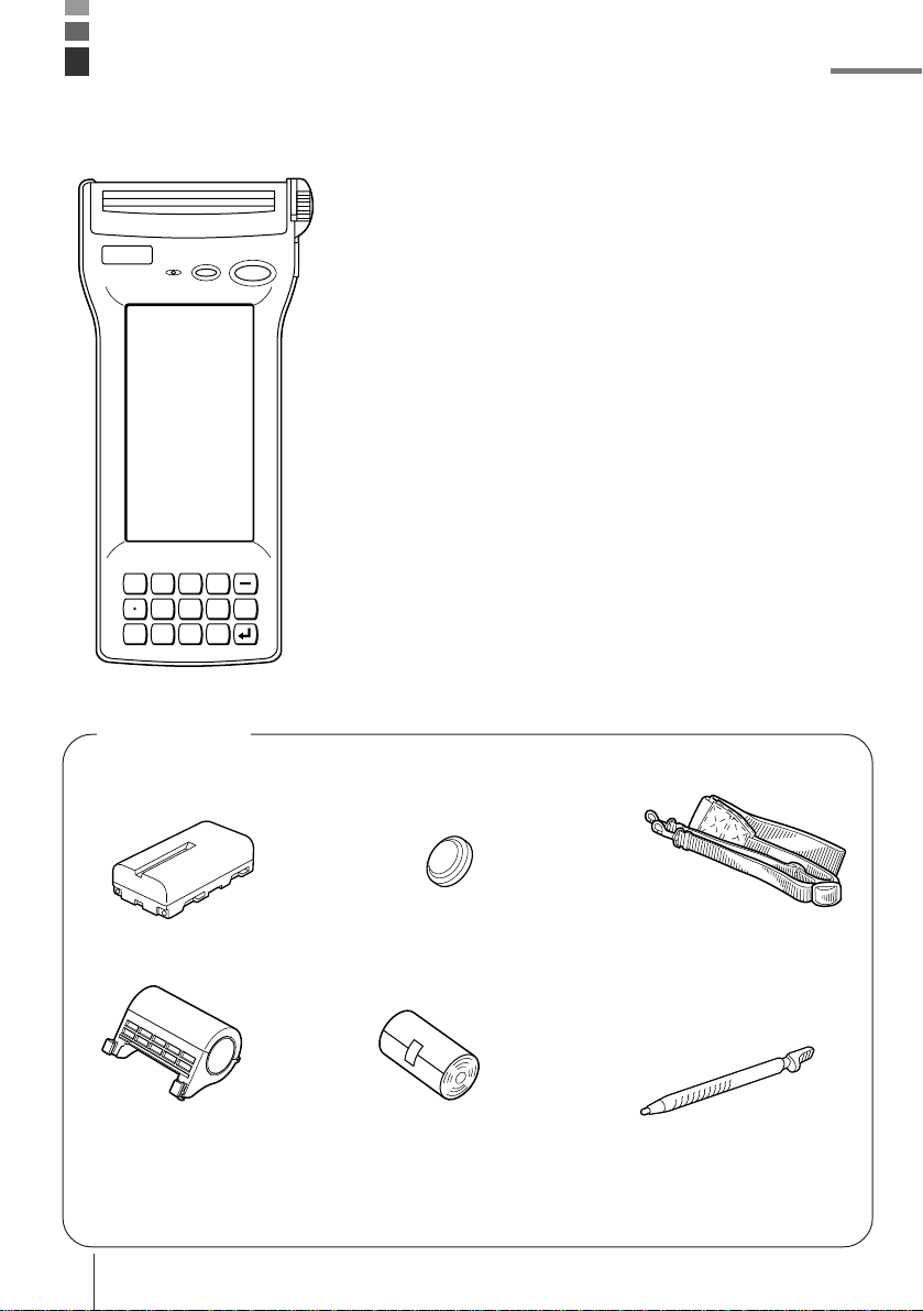
IT-2000 Series System Configuration
7Fn 8 9
456
0123
CLR
Accessories
• Lithium ion Battery
Pack
• Paper holder
E-14
• Backup Lithium Battery
• Paper roll
• Neck Strap
• Stylus
Placed to the right side of
the Data Collector
• Manual
Page 14
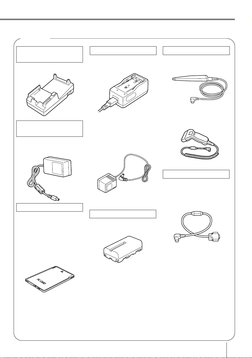
Options
Optical
Communication Unit
IT-2060IOE
AC adaptor for
Communication Unit
DT-825ADP-G
DT-825ADP-U
PC Cards
DT-9031BFMC
(FROM 4MB)
DT-9033BFMC
(FROM 10MB)
DT-9034BFMC
(FROM 20MB)
Optical
Charger
DT-9021CHGEU
DT-9020ADP-G
DT-9020ADP-U
Lithium ion Battery Pack
DT-9023LI
Bar-code reader
DT-9650BCR
DT-9656BCR
Cable
DT-9689AX
(between Data Collector
and personal computer)
DT-881RSC
(modem-used)
DT-882RSC
(cross connection, male)
DT-883RSC
(cross connection, female)
DT-887AX
(AX-used, cross connection)
DT-888RSC
(Optical Communication
Unit-used)
E-15
Page 15
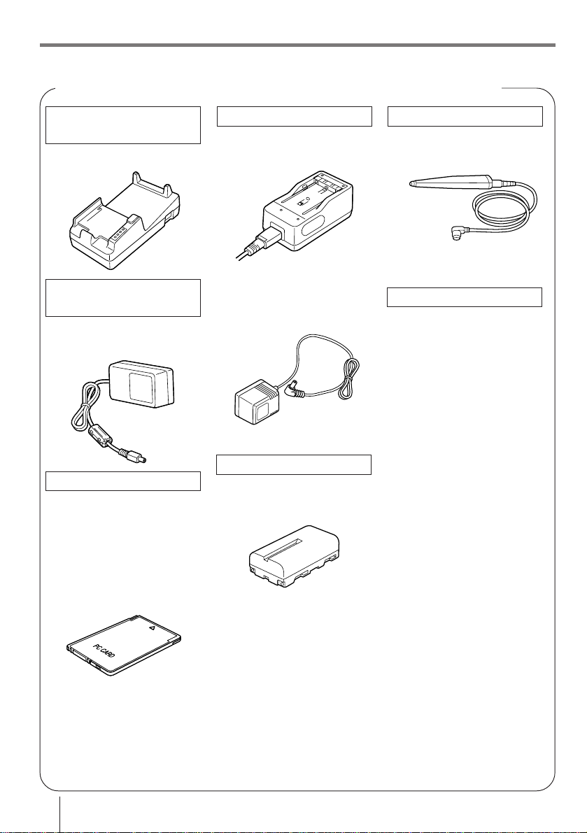
IT-2000 Series System Configuration
Available Options for the IT-2000 Series American Market Models
Optical
Communication Unit
IT-2060IOE
AC adaptor for
Communication Unit
DT-825ADP-U
PC Cards
DT-9031BFMC
(FROM 4MB)
DT-9033BFMC
(FROM 10MB)
DT-9034BFMC
(FROM 20MB)
Optical
Charger
DT-9021CHGEU
DT-9020ADP-U
Lithium ion Battery Pack
DT-9023LI
Bar-code reader
DT-9650BCR
Cable
DT-881RSC
(modem-used)
DT-882RSC
(cross connection, male)
DT-883RSC
(cross connection, female)
DT-887AX
(AX-used, cross connection)
DT-888RSC
(Optical Communication
Unit-used)
E-16
Page 16
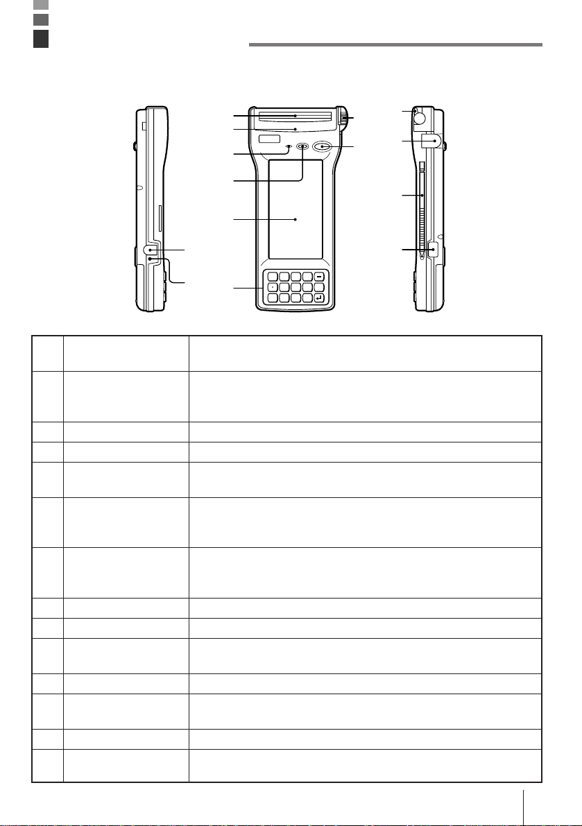
General Guide
Left Front Right
1 Lithium ion battery
pack charger connector
2 Charge indicator
3 Paper cutter
4 Printer cover
5 Buzzer
6 Light sensor
7 LCD/Touch panel
8 Key pad
9 Feeding dial
10 Power switch
11 Head-up lever
12 RS-232C interface
connector
13 Stylus pen
14 Infrared interface
3
4
5
9
10
11
12
6
13
7
1
2
8
For connection of the charger to charge the lithium ion battery pack.
Protected by a cover that must be opened for connection.
Stays lit while the lithium-ion battery pack is being charged, and goes
out after charging is complete. Lights momentarily when the charger
is connected even when the battery pack is charged.
Cuts the printed paper roll.
Remove this cover to remove paper when a paper jam occurs.
Emits audible signals to confirm certain operations. Make sure that
buzzer holes are not blocked so that signals can be heard.
Detects available light. This sensor switches the backlight on (when
dark) and off (when bright). For proper operation, make sure that this
sensor is not blocked.
Display data during program execution or debugging. Also provides
touch panel keys for input by touching the screen with a finger or the
stylus pen that comes with the Data Collector.
15 keys including 10-key pad and execute key.
Used when installing roll paper or feeding paper manually.
Press to turn power on and off, or to restore power after auto power
off operation.
Lift this lever up when installing or replacing a paper roll.
For connection of a bar code reader or other external device.
Protected by a cover that must be opened for connection.
For touch panel operations.
Communication port for data exchange between two Data Collectors
or with the I/O box.
7Fn 8 9
456
0
123
CLR
14
E-17
Page 17
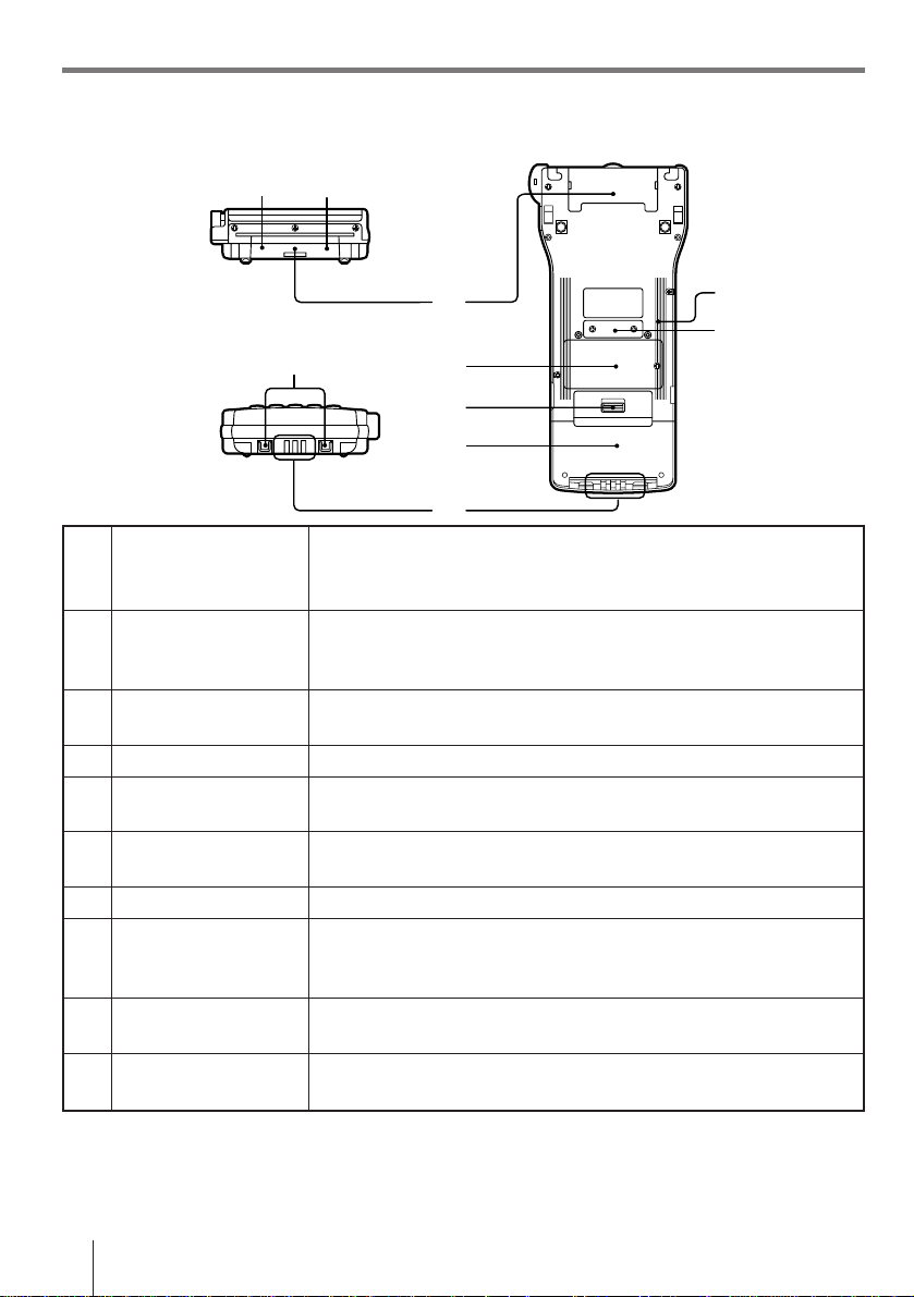
General Guide
Top Back
15 16
Bottom
15 PC card lock button
(inside PC card slot
cover)
16 PC card eject button
(inside PC card slot
cover)
17 PC card slot cover
18 Neck strap bars
19 Charger terminals
20 Backup battery
compartment
21 Open button
22 Lithium-ion battery
pack compartment
connector
23 Initialize button
24 14-pin serial interface
connector
17
23
24
18
20
21
22
19
Locks optional PC card in place.
Make sure that this button is in the LOCK position when using a PC
card.
Press this button (after opening the PC card slot cover and setting the
PC card lock button to FREE) to eject a PC card installed in the Data
Collector.
Insert the optional PC card here when installing.
Open when inserting a PC card.
For connection of the neck strap.
These terminals mate with the I/O box to receive electrical power for
charging the lithium-ion battery pack.
Houses the lithium-ion battery used for memory backup.
Slide to open the battery pack cover.
Houses the lithium-ion battery pack that is the Data Collector’s main
power supply.
Use a paper clip or other thin, pointed object to press this button to
launch the Data Collector’s system initialization routine.
For connection of future expansion options.
Note! Pressing the Initialize button clears all data and programs from memory.
Never press the Initialize switch unless absolutely necessary.
E-18
Page 18

Installing and Removing Batteries
Your Data Collector is powered by a rechargeable lithium ion battery pack and a lithium
backup battery.
Main power supply
See page E-26 for details on how to recharge the battery pack.
To install the battery pack
1 Slide the battery pack compartment open
button in the direction indicated by the arrow
in the illustration, and open the cover.
Open button
2 With the indentation of
the battery pack facing
up (so you can see it),
install the battery pack
into the compartment as
shown in the illustration.
Make sure that the
battery pack’s terminals
are facing in the correct
direction. Next, slide the
battery pack in the
direction shown in the
illustration so that it
locks into place.
3 Close the battery pack compartment cover.
Close the cover and then slide the open
button in the direction indicated by the arrow
to secure the cover in place.
Note that the battery pack will not supply
power correctly unless the battery pack
compartment cover is closed securely.
Double check to make sure that the cover of
your unit is closed correctly.
E-19
Page 19

Installing and Removing Batteries
To remove the battery pack
Always make sure that Data Collector power is turned off before removing the battery pack.
Also, never remove the backup batteries while the battery pack is removed. Doing so will
cause all memory contents to be deleted.
1 Slide the battery pack compartment open
button in the direction indicated by the arrow
in the illustration, and open the cover.
Open button
2 Slide the battery pack in the direction shown
in the illustration and then remove it.
Important! • The power of the battery pack is depleted by testing prior to shipment
and by natural discharging during shipping and storage. Be sure to
use the procedures on page E-26 to charge the battery pack before
using the unit for the first time.
• Charge the battery pack as soon as possible when the buzzer sounds
intermittently to notify you that battery power has dropped.
• Always make sure that the Data Collector is turned off before opening
the lithium ion battery pack compartment cover. When the battery pack
compartment cover is opened, an alarm tone sounds. This is to
prevent the battery pack from being removed while the power is ON.
This can cause loss of memory data and system malfunction when
power is turned back on.
• Make sure that the battery pack never becomes shorted. A short can
cause damage to the battery pack.
• Repeated charges cause deterioration of the battery pack. If you find
that your battery pack does not provide enough operation even after
you bring it to a full charge, it probably means it is time to replace it.
• If you do not plan to use the Data Collector for a long time, protect
against running down the power of the backup batteries by fully
charging the battery pack.
E-20
Page 20

Backup batteries
The backup batteries protect the units memory contents whenever power from the main
battery pack is interrupted due to replacement of the battery pack, when the battery pack is
dead, etc.
Two lithium batteries are used for backup. The #2 backup battery is installed in the Data
Collector prior to shipment, but you must install the #1 backup battery that comes with the
Data Collector before using it for the first time.
Important! Dual backup batteries are employed in order to protect the #1 backup
battery from going dead. Note that memory contents cannot be
protected by the #2 backup battery alone.
To install the #1 backup battery
1 Loosen the screw that secures the backup
battery compartment cover in place. The
cover is designed so the screws cannot be
removed from the holes in order to protect
against particles falling out of the screw
threads into the battery compartment.
2 Lift up the side of the cover indicated in the
illustration, and then slide the cover in the
direction indicated by the arrow. Make sure
you do not damage the tab on end of the
cover.
3 Loosen the screw that holds the #1 backup
battery holder in place, and remove the
holder. The cover is designed so the screws
cannot be removed from the holes in order to
protect against particles falling out of the
screw threads into the battery compartment.
#2 backup battery
#1 backup battery
E-21
Page 21

Installing and Removing Batteries
4 Wipe the surface of the lithium battery you
will install with a soft, dry cloth. Load the
battery into the Data Collector so that its
positive (+) side faces up (so you can see it).
5 Insert the tabs of the backup battery holder
into the slots provided, and secure it in place
with its screw.
6 Carefully replace the backup battery
compartment cover. Insert the tab of the
cover into the slot provided.
7 Secure the cover in place with its screw.
Important! • Whenever you remove the #1 backup battery and the main power
supply’s battery pack at the same time, memory contents are lost,
regardless of whether or not the #2 backup battery is installed. The #2
back-up battery alone does not protect memory contents.
• Never remove the #2 backup battery from the Data Collector.
• Always make sure that the + side of the lithium batteries are facing up
(so you can see them) when installing them into the Data Collector.
• Before replacing the #1 backup battery, always check to make sure that
the lithium ion battery pack’s power is not low first. Replacing the #1
backup battery while the lithium ion battery pack’s power is low can
result is loss of all data stored in Data Collector memory.
E-22
Page 22

Position of the Keys
IT-2000 key part consist of 16 keys, including the power key.
Position of stroke keys
3
1
2
1 Function key
2 Number keys, decimal
key, minus (–) key
3 Power key
4 Clear key
5 Execution key
7Fn 8 9
456
0123
CLR
4
5
Used for setting various program functions.
Combined with one or two of the ten keys (0 to 9).
Used for input of numbers. Press decimal point key to mark the
position of the decimal point.
Used for switching the power on/off.
Also, it is used for power on during the auto power off condition.
Clears’ previous input.
Confirms input and leads to the next step.
E-23
Page 23

CALIBRATION
Carefully press on
the center of the
each cross by PEN.
1.SYSTEM MENU
2.RETRY
3.EXIT
Position of the Keys
Touch key panel
The touch panel appears on the Data Collector’s LCD. Be sure to use only your finger or the
stylus that comes with the Data Collector to operate the touch panel.
Using the touch panel stylus
The touch panel stylus is attached to the right
side of the Data Collector.
Important! Use the procedure below to calibrate the touch panel whenever it
appears that it is misaligned on the LCD.
To calibrate the touch panel
1 Use a paper clip or some other thin, pointed
object to press the Initialize button on the
back of the Data Collector. This launches the
system initialization routine, which causes
the touch panel calibration screen shown
nearby to appear on the LCD.
2 Touch the center of each cross with the
stylus in the sequence indicated by the
arrow.
3 The touch panel calibration screen will be
cleared automatically after you touch all four
crosses.
E-24
Page 24

System Initialization Routine
The system initialization routine is performed when you turn on the Data Collector for the
first time after purchasing it and whenever you press the Initialize button.
The following is the operational flow for the system initialization routine.
Press the power switch.
Self-diagnostic check of RAM and hardware,
followed by launch of MS-DOS.
Touch panel calibration screen and menu
appear, offering the following options.
Touch Panel Calibration
This procedure corrects
misalignment of input points
on the touch panel (page
E-24).
Press the Initialization button.
SYSTEM MENU EXIT
Launches the system
maintenance program,
which is used for installing
application programs and
other management tasks.
Exits the system
initialization routine without
calibrating the touch panel.
Important! Every time you turn on power, the system normally searches for an
application program in the following sequences: memory card, RAM
disk, F-ROM disk. The system initialization routine is launched only if
memory contents have been lost (due to both the lithium ion battery
pack and backup battery going dead) or if an application program
cannot be found.
E-25
Page 25

Charging the Battery Pack
The lithium ion battery pack is the Data Collector’s main power supply that provides power
for normal operations and memory backup. This means it is important to recharge or replace
the battery pack as soon as possible after the low battery message appears on the LCD.
Battery pack charging can be performed using any of the following options: DT-9021CHGEU
Single Charger, DT-9020ADP-G/DT-9020ADP-U Charger.
To charge the battery pack
1 Insert the power cord into the battery pack as
far as it can go.
Plug the charger unit’s power cord into a
power outlet.
2 Slide the battery pack in the direction
indicated by the arrow in the illustration to
install it onto the charger unit. The charge
indicator (orange) lights at this time to
indicate that the battery pack is being
charged.
Not used
3 After the charge indicator goes out (indicating
that charging is complete), slide the battery
pack in the opposite direction and remove it
from the charger unit.
Charging time
Charging time: approximately 2 hours and 30 minutes
Note! The above times may differ depending on the temperature in your area.
E-26
Charge indicator
Page 26

To charge battery packs using the Charger
1 Press the Data Collector’s Power switch to
turn off power.
2 Plug the charger into an electrical outlet, and
then attach the charger to charger connector
on the side of the Data Collector.
3 The Data Collector’s charge indicator lights
to indicate that the charge operation is being
performed. Charging is complete when the
charge indicator is no longer lit. It takes about
ten hours to achieve a full charge.
Important! • Removing the lithium ion battery pack from the Data Collector
consumes backup lithium battery power, which is used to retain data
in memory. This is no problem for short periods, but leaving the Data
Collector without a charged lithium ion battery pack for long periods
can cause the backup battery to go dead, resulting in loss of all
programs and data stored in Data Collector memory. Because of this,
we recommend that you keep charged battery packs on hand for use
while other battery packs are being charged.
• Long use of a lithium ion battery pack gradually shortens the amount
of operating time it provides after each charge. This is normal for the
lithium ion battery pack and does not indicate malfunction. If you find
that the amount of time provided by your battery pack is too short, it is
probably time to replace it with a new one.
• Never try to use the DT-9021CHGEU or DT-9020ADP-G/DT-9020ADP-U
charger to charge any other type of battery pack.
• Avoid locations subject to vibration when performing the charge
operation.
• The battery pack discharges even when it is not loaded in the Data
Collector. Make sure you load the battery pack into the Data Collector
within at least one or two days after it is charged.
• It is recommended that a battery pack be removed from the DT9021CHGEU or DT-9020ADP-G/DT-9020ADP-U charger within about 24
hours after full charge is attained.
E-27
Page 27

Attaching the Neck Strap
Length adjustment
Neck strap
Hooks
To attach the neck strap
Pulling back on the spring latches on the neck
strap hooks, attach the neck strap to the Data
Collector’s neck strap bars. Next, release the
latches to secure the neck strap in place.
To detach the neck strap
Pulling back on the spring latches on the neck
strap hooks, remove the neck strap to the Data
Collector’s neck strap bars.
Important! Never allow the Data Collector to swing around by the neck strap.
E-28
Page 28

Data Communication
You can exchange data between two Data Collectors or between a Data Collector and a
personal computer.
Exchanging Data Between Two Data Collectors
You can transfer applications and data to another Data Collector using the infrared interface.
The illustration below shows how two Data Collectors must be oriented for data
communication.
• Make sure that the infrared interfaces of both Data Collectors are not blocked.
• Communication is possible between two Data Collectors that are spaced from 0 (direct
contact) to 1 meter apart.
Exchanging Data with a Personal Computer
You can exchange data between a Data Collector
and personal computer by connecting them with
an RS-232C cable.
Be sure to turn the power off before connecting
the cable.
CAUTION! For IrDA transmission function,
high sensitivity element is used in this unit.
Avoid the proximity of a unit or equipment such as a cellular phone
emitting electrical current during data communication.
To get a smooth transfer using this unit, keep some distance from the
equipment (at least 30 centimeters from a cellular phone).
E-29
Page 29

Handling the Printer
The IT-2000D33E/53E printer uses roll paper and paper tape for printing.
Using Roll Paper
If you wish to use roll paper, you must first install the paper holder and then load the paper.
Installing and Removing the Paper Holder
Installing
Insert the jagged part of the paper holder into
the paper holder fixing.
If the paper holder is not inserted properly,
this may result in a roll paper jam or paper
feed trouble. Make sure that both sides of the
paper holder are inserted into the paper
holder fixing as far as they can go.
Removing
Holding the body, unhook the claws on both
sides under the paper holder, and slide the
paper holder downwards to remove.
Opening the Paper Holder
Press both sides of the holder to open it.
E-30
Page 30

Loading Roll Paper
To use the printer, you must first load paper.
If you print without paper, it may damage the printer.
1 Lift the head-up lever.
Next, open the paper holder.
2 Put roll paper in the lid of the paper holder.
3 Feed paper until it stops.
Slot
Head-up lever
Roll paper
4 Turn the feeding dial in the direction of the
arrow until the paper appears on the paper
cutter side.
Release the head-up lever by returning it to
its original position.
Feeding dial
E-31
Page 31

Handling the Printer
5 Close the paper holder.
Note! • When you insert or change roll
paper, move the head-up lever to
position
return it to position
• When you turn the feeding dial,
be sure to move the head-up
lever to position
not paper is loaded).
• Always load the paper as shown
in the figure below.
22
2. When you print out,
22
11
1.
11
22
2 (whether or
22
Feeding dial
Head-up lever
➁
➀
E-32
Printer Paper roll Printer Paper roll
Page 32

Removing the Printer Cover
When a paper jam occurs, open the printer cover and remove the cause of the paper jam.
Be careful because the inside of the printer may be hot.
1 Turn the power off and open the paper holder
cover.
2 Place the roll paper on the paper holder
cover.
Slide the printer cover as shown in the figure,
and gently lift up the edge of the printer cover
to remove.
E-33
Page 33

Handling the Printer
Using Paper Tape
There are two ways of feeding paper tape into the IT-2000D33E/53E with the paper tape.
You can either use the auto-loading function or you can load paper tape manually (set this in
the software).
Keep the paper holder cover open when using the paper tape with the paper holder.
Setting Automatic Feed (auto-loading)
1 Lift the head-up lever to the head-up position.
2 Feed paper with the printing surface facing
down until it stops. The paper will be
automatically set into printing position.
3 Be sure that the paper is loaded properly and
return the head-up lever to its initial position.
Note! If a Paper Jam Occurs During Auto-loading
• Make sure that the printer is stopped by bringing the head-up lever to
the head-up position. Turn the feeding dial to the opposite direction to
remove jammed paper and then load the paper by repeating usual
procedure.
E-34
Feeding dial
Page 34

Loading Paper by Hand
Follow the procedure below when Auto Loading is disabled (set this in the software).
1 Lift the head-up lever to the head-up position.
2 Insert single-ply paper with the printing
surface facing down into the paper slot as far
as it will go.
3 Turn the paper feeding dial in the direction of
the arrow to feed the paper to the printing
position.
Then return the head-up lever to its original
position.
Feeding dial
E-35
Page 35

Handling the Printer
Things to Remember When Using the Printer
1. Printing Intensity
1 Printing speed may be slow and a one-dot difference between two lines may occur during
high-duty printing, such as printing charts, etc. This is to prevent excessive current.
2 The LF error may occur if there is more than a one-second interrupt between printing
individual lines. When paper tape is used, set a larger printing area or continuous printing.
3 If battery low (low battery pack voltage) is detected, the print job will be stopped. However,
after you resume printing, a one-dot difference between two lines or reduced character
spacing may occur.
4 After you feed paper by turning the feeding dial, the characters may be printed with
reduced character spacing. You can avoid this by using the program to load paper before
printing.
5 If some problem occurs on the printer, immediately turn the power off, and remove the
cause of the problem before starting to the Data Collector again. If you cannot remove the
cause of the problem, contact a CASIO service provider.
6 Print without printer paper loaded can impair the head or damage drive system
components. Be sure to load printer paper before you start printing.
7 Use only recommended printer paper.
Use of other printer paper can adversely affect printing quality and the service life of the
printer, and can result in loss of performance.
8 Pay attention to the following points when storing printer paper:
• Temperatures above 60°C may cause the paper to discolor naturally. Do not store
printer paper in high temperature or humid locations.
• Store printer paper in a cool, dark location. Also, do not leave printer paper in the direct
sunlight for long periods.
• Plastic film containing plasticizer, ester-based rubber erasers, or tape glue or adhesive
can cause fading, and contact with organic solvents and diazzo copy paper, and
fingernail scratches can cause coloration.
2. Other
1 The operating temperature is 5 to 35°C is during printing on 2-ply and label paper.
2 Insert new paper when the red end mark starts to appear on the paper you use.
3 Recommended paper: Use only CASIO-specified printer paper.
4 Store the IT-2000D33E/53E with the head-up lever down when it is not to be used for a
long time.
5 Do not turn the feeding dial just after printing is finished. Doing so might damage the
feeding dial.
6 If the printer is used for a long period, paper scraps can accumulate and impair printing
quality. If this happens, the thermal head must be cleaned. Contact a CASIO service
provider.
Warning! Do not touch the thermal head during and just after printing is finished.
E-36
Page 36

IT-2000’s Specifications
CPU: 32 bit CPU
RAM: IT-2000D33E: RAM 4 MB + Flash ROM 8 MB
Display: VGA interface,
Input: Touch key/touch panel method
Infrared: Interface: Conformed IrDA1.0 or IrDA1.1 Standard
Serial communication:
14-pin serial communication:
Other: Clock functions: second, minute, hour, day of the week, day, month, year
Power supply: Main power source: Lithium ion battery pack
Operating temperature:
Dimensions (Approximate):
Weight (Approximate):
IT-2000D53E: RAM 4 MB + Flash ROM 16 MB
16 grayscale (only 4 grayscale visible) monochrome, 384 (V)
x 192 (H) dots
Display contrast adjusting: auto modifying
EL backlight (auto-off function, 20 - 300 sec. in 20-second units), auto ON/OFF
16 stroke keys (including the power key)
Synchronization: Asynchronous (IrDA1.0)
Transfer rate: Conformed IrDA Ver. 1.0: ~ 115.2 Kbps
Interface: RS-232C level interface
Synchronous mode: Asynchronous
Transfer rate: 1,200 bps - 115.2 Kbps
Interface: RS-232C level interface
Synchronous mode: Asynchronous
Transfer rate: 1,200 bps - 115.2 Kbps
Full auto-calendar
Buzzer sound: 3-level volume + OFF possible (depending on the software)
Memory back-up battery:
Battery life: Lithium ion battery pack: 8 hours (stand-by)
Memory back-up battery: 1 week
Battery checker: Both for the main power battery and for the
Auto power-off function (1 - 15 minutes, setting in minutes of one)
–5°C - 50°C (23°F - 122°F)
85<100> (W) x 225 (L) x 29<34.4> (H) mm (3 11/32 x 7 11/16 x 1 3/16 inch)
Figures in <> brackets indicate dimensions with printer attached.
540 g
Frame synchronization (IrDA1.1)
Conformed IrDA Ver. 1.1: ~ 4 Mbps
Lithium batteries CR2032 (#1) and IVR2430 (#2)
back-up battery (CR2032)
E-37
Page 37

IT-2060IOE Optional Optical Communication Unit
The IT-2060IOE Optional Optical Communication Unit makes it possible to quickly and
easily exchange system data and file data with a personal computer. The Optical
Communication Unit can also be used to charge the Data Collector’s lithium ion battery
pack. RS-232C cables (DT-881RSC, DT-882RSC, DT-883RSC, DT-887AX) are available to
connect the Optical Communication Unit to a personal computer.
General Guide
1
2
3
11
4
5
12
E-38
6
7
8
9
10
Page 38

1 RS-232C interface
connector
2 RS-422 interface
connector
3 AC adaptor jack
4 Connection detector
5 Infrared interface
6 Charge connectors
7 System status indicator
8 Communication status
indicator
9 Charge indicator
10 Power indicator
11 Power switch
12 DIP switches
For connection of an RS-232C cable to exchange system data and file
data with a personal computer.
For connection of a cable to daisy chain with another Optical
Communication Unit.
For connection of the AC adaptor, which supplies power.
Detects whether the Data Collector is correctly mounted onto the
Optical Communication Unit.
Non-contact communication port for data exchange with the Data
Collector.
These connectors mate with Data Collector connectors to provide
electrical power to the Data Collector.
Indicates the operational status of the system.
Off: System problem or failure to establish communication
with all Data Collectors mounted on daisy chained
Optical Communication Units.
On (green): Normal operation, communication established with all
Data Collectors.
Indicates the status of communications.
Off: No communication being performed.
Flashing (green): Communication being performed.
On (red): Optical Communication Unit connection
problem
Indicates the charge status of the Data Collector’s lithium ion battery
pack.
Off: No charging being performed.
On (red): Charging
Indicates the on/off status of the Optical Communication Unit and the
status of the connection between the Optical Communication Unit and
the Data Collector.
Off: Power off
On (red): Power on, no Data Collector mounted
On (green): Power on, Data Collector mounted
Turns power on and off.
Switches for configuring the Optical Communication Unit.
E-39
Page 39

IT-2060IOE Optional Optical Communication Unit
Connecting the Optical Communication Unit to a Power Source
Use only the specified AC adaptor to connect the Optical Communication Unit to an
electrical outlet. Be sure to connect the AC adaptor and turn on Optical Communication Unit
power before attempting to perform any data communication operation with the Data
Collector. The Optical Communication Unit supplies power to a Data Collector mounted on it.
To connect to a power source
1 Plug the AC adaptor into an electrical outlet.
2 After making sure that the power switch of
the Optical Communication Unit is turned off,
connect the AC adaptor to the AC adaptor
jack at the top of the Optical Communication
Unit.
3 After checking to make sure that the power of
the Optical Communication Unit and the
computer you are connecting to is turned off,
connect the RS-232C interface connector at
the top of the Optical Communication Unit to
the serial port of the computer using the
cable (DT-881RSC, DT-882RSC, DT883RSC, DT-887AX).
Keep the Optical Communication Unit’s RS232C interface connector cover whenever it
is not in use.
4 Turn on the Optical Communication Unit, and
its power indicator should light up red.
5 Mount the Data Collector onto the Optical
Communication Unit making sure that their
infrared interfaces align correctly with each
other. The power indicator of the Optical
Communication Unit should change to green
at this time.
• The system status indicator lights up green
when the system is operating correctly,
both during communication and
communication standby (when two or more
Optical Communication Units are daisy
chained).
• The communication status indicator
flashes green while communication is
being performed.
To electrical outlet
Power
switch (off)
Infrared
interfaces
Power switch
(on)
System status indicator
Communication status indicator
Charge indicator
Power indicator
E-40
Page 40

CAUTION! For IrDA transmission function, high sensitivity element is used in this
unit.
Avoid the proximity of a unit or equipment such as a cellular phone
emitting electrical current during data communication.
To get a smooth transfer using this unit, keep some distance from the
equipment (at least 30 centimeters from a cellular phone).
Using the Optical Communication Unit to Charge the Data Collector Battery Pack
1 Turn on the Optical Communication Unit, and
its power indicator should light up red.
Infrared
interfaces
2 Mount the Data Collector onto the Optical
Communication Unit making sure that their
charger connectors join securely with each
other.
If the Data Collector is turned off, it will turn
on automatically once a power connection is
established (this feature can be disabled by
software).
The power indicator of the Optical
Communication Unit should change to green
at this time, and the charge indicator should
light up red to indicate that the battery pack is
being charged.
Important! • Use the charger units designed for this product to charge the specified
battery packs only. Never try to charge another type of battery pack.
• The battery pack discharges even when it is not loaded in the Data
Collector. Make sure you load the battery pack into the Data Collector
as soon as possible after it is charged.
• Recharge the battery pack at a temperature between 0°C (32°F) and
40°C (104°F). Charging outside this range can cause leaking of battery
fluid and generation of heat by the battery. It can also reduce battery
performance and shorten battery life.
• To ensure proper battery pack charging, periodically wipe off the
charge connectors of the Optical Communication Unit and Data
Collector with a cotton swab or soft, dry cloth.
System status indicator
Communication status indicator
Charge indicator
Power indicator
Power
switch (on)
E-41
Page 41

IT-2060IOE Optional Optical Communication Unit
Daisy Chaining Optical Communication Units
An optional DT-888RSC 6-6 Pin Modular Cable can be used to daisy chain up to seven
Optical Communication Units. In this configuration, a personal computer can exchange data
with multiple Data Collectors simultaneously.
Daisy Chain Configuration
Connect the C-OUT terminal of the Optical Communication Unit that is closer to the host
computer to the C-IN terminal of the next Optical Communication Unit.
The following are the required DIP switch settings for Optical Communication Units in a
daisy chain configuration. See page E-43 for details on actually making DIP switch settings.
• The Optical Communication Unit furthest from the computer must be defined as the
“Terminator Unit in Linked Chain.”
• The Optical Communication Unit connected to the computer must be defined as the “Host
Computer Connection.”
• All other Optical Communication Units must be defined as “Intermediate Unite in Linked
Chain.”
E-42
Page 42

DIP Switch Settings
12345678910
Flow Control
910
Off OFF OFF
X ON/X OFF ON OFF
RS/CS OFF ON
Use Special Software ON ON
Optical Communication Unit - Host
Computer Communication speed
67 8
2,400bps OFF OFF OFF
4,800bps ON OFF OFF
9,600bps OFF ON OFF
19,200bps ON ON OFF
38,400bps OFF OFF ON
57,600bps ON OFF ON
115,200bps OFF ON ON
* Communication speed can be set by
Data Collector overrides this setting.
Connection T ype
345
Data Collector - Optical Communication
Unit Communication Speed
12
38,400bps OFF OFF
115,200bps ON OFF
Host Computer OFF OFF ON (No linking)
Connection OFF (Linking)
Intermediate Unit
in Linked Chain
Terminator Unit
in Linked Chain
ON OFF OFF
ON OFF ON
Important! Other settings not shown here are used for special-purpose modes, and
should not be used.
E-43
Page 43

IT-2060IOE Optional Optical Communication Unit
IT-2060IOE Optical Communication Unit Specifications
Infrared Communication
Interface: Infrared
Conformed IrDA Ver. 1.0
Synchronization: Asynchronous
Baud Rate: 9,600/38,400/115,200 bps
RS-232C
Synchronization: Asynchronous
Baud Rate: 2,400 to 115,200 bps
Transmission Protocol: Full-duplex
RS-422
Synchronization: Asynchronous
Baud Rate: 9,600/38,400/115,200 bps
Output Power
Output: 12 V DC/500 mA
Charging specifications
Charging time: Approximately 10 hours (with Data Collector power off)
Charging time increases with Data Collector power on
Power Supply
Source: Specified AC adaptor
Consumption Current: Approximately 600 mA (maximum during output of power for
charging)
AC Adaptor
Model: DT-825ADP-G Input: 230 V AC 50/60 Hz
Output: 12 V DC 1,400 mA
DT-825ADP-U Input: 120 V AC 50/60 Hz
Output: 12 V DC 1,400 mA
Functions
Infrared interface
RS-232C interface
RS-422 interface
Operating temperature
0°C - 40°C (32°F -104°F)
Dimensions
Approximately 110 (W) x 220 (D) x 80 (H) mm
(4 5/16 x 8 5/8 x 3 1/8 inch)
Weight
Approximately 370 g (13.0 oz)
E-44
Page 44

Handling Bar-Code Reader
Connect the bar-code reader to the Data Collector’s bar-code reader connector.
There are two models of bar-code reader: pen scanner DT-9650BCR, touch scanner DT9656BCR.
Connecting the bar-code reader
Turn the power on the Data Collector off.
1
Open the cover of the bar-code reader
connector.
2 Insert the plug of the bar-code reader into the
connector as shown on the picture.
Detaching bar-code reader
Turn the power on the Data Collector off. Unplug the bar-code reader connector.
Cover
Using a bar-code reader
<Pen scanner>
1 Bar code scanning angle
Reading power: 0.19 mm (for PCS value of 0.85)
Wand position Effective angle
Angle (up to 45 degrees)
E-45
Page 45

Handling Bar-Code Reader
2 Bar code scanning position
Start
Margin Margin
Correct Correct Correct
Correct Wrong Wrong
Stop
E-46
Wrong Wrong
Wrong
Page 46

<Touch scanner>
1 Bar-code touching angle (at read resolution 0.33mm, PCS 0.45)
How to hold the wand
non-contact distance (h) h = 0 ~ 10 mm
α = 0
β = 0
R = ∞
h
Angle between the bar-code and forward/backward inclined reading window (α)
1α = 0 ~ 10° (front part is inclined forward)
2α = 0 ~ 30° (back part is inclined backward)
h = 0
β = 0
1α 2α
R = ∞
The angle of inclination to the right/left (β)
β = 0 ~ 10°
h = 0
α = 0
β
Curve (R) R = 25 mm and above
h
R
β
R = ∞
(at read resolution 0.33, PCS value 0.45)
h = 5 mm
α = 0
β = 0
h, α, β, R are commonly defined.
Position of bar-code must be in the center of the
reading window.
E-47
Page 47

Handling Bar-Code Reader
2 Bar-code touching angle
Margin Margin
Correct Correct Correct
Wrong Wrong Wrong
Wrong
<Sample bar-codes>
• These bar-codes are samples.
E-48
EAN CODE39
(Standard version)
EAN UPC
(Shorten version)
NW-7
Page 48

Bar Code Reader Specifications
DT-9650BCR Pen Scanner
Readable Codes: WPC (JAN, EAN, UPC), NW-7, CODE-39/93/128, ITF
Readable PCS Value: 0.45 min.
Cable Length: Approximately 100 cm
Read Resolution: 0.125 mm min. (PCS value 0.85 min.)
Read Angle: 90 to 45 degrees
Scan Speed: 76 to 760 mm/second
Operating Temperature/Humidity:
–10 to 50°C (14 to 122°F)/15 to 90% RH
Dimensions: Approximately 147 (W) x 20.6 (D) x 12.5 (H) mm
(5 3/4 x 13/16 x 1/2 inch)
Weight: Approximately 85 g (3.0 oz)(including cable)
DT-9656BCR Touch Scanner
Readable Codes: WPC (JAN, EAN, UPC), NW-7, CODE-39/93/128, ITF
Readable PCS Value: 0.45 min.
Cable Length: Approximately 60 cm (extended)
Read Resolution: 0.127 mm min. (PCS value 0.9 min.)
Non-contact Distance: 0 to 20 mm
Read Angle:
Forward: 10 degrees
Back: 30 degrees
Left/Right: ±10 degrees
Rotating: ±10 degrees
Curved: R = 25 mm min. (with resolution of 0.33 mm)
Read Width: 60 mm
Operating Temperature/Humidity:
0 to 40°C (14 to 122°F)/20 to 80% RH
Dimensions: Approximately 161 (W) x 64.4 (D) x 59 (H) mm
(6 11/16 x 3 x 2 inch)
Weight: Approximately 250 g (8.8 oz)(including cable)
E-49
Page 49

Using PC Cards
Your Data Collector supports use of a variety of PC cards (FROM), which are available as
options. FROM cards are available in different capacities, so you can select the one that
best suits your needs.
To load a memory card into the Data Collector
1 Turn off the Data Collector, turn it over, and
lift up the PC card slot cover while pressing
the projection as shown in the illustration.
2 Slide the PC card lock
button in the direction of
the arrow to release
LOCK and then slide the
end of the PC card
marked with
Data Collector. The
arrow should be facing
up (so you can see it).
into the
Make sure the
facing up (so you can see
it). The location of the
mark differs according to
the card you are using.
mark is
3 Slide the PC card lock button to the LOCK
position.
E-50
Lock
button
Page 50

Important! • The PC card is not detected by the Data Collector when the PC card
lock button is in the LOCK release position. Sliding the PC card lock
button to the LOCK release position while the Data Collector is turned
on causes power to turn off automatically. Interrupted operations can
result in system malfunction when the Data Collector is turned back
on.
• Improper installation of a PC card can result in system malfunction and
inability to read the card.
To remove a card from the Data Collector
1 Turn off the Data Collector, turn it over, and
lift up the PC card slot cover while pressing
the projection.
2 Slide the PC card lock button in the direction
of the arrow to release LOCK and then press
the PC card eject button to eject the PC card.
Remove the PC card from the Data Collector.
Important! Forcing the PC card eject button without first sliding the PC card lock
button to the LOCK release position can damage the internal mechanism
of the Data Collector. Make sure you carefully follow the steps of the
procedures described above whenever inserting or removing a PC card.
PC card eject
button
E-51
Page 51

Attaching the Screen Protective Cover
Attaching the screen protective cover to the IT-2000D33E/53E prevents the screen from
becoming scratched and split, for example, during transportation.
1 Remove the touch panel pen that is
contained on the right side of the body.
2 Attach the movable attachment fixture on the
side of the screen protective cover at the
location where the touch panel pen was
attached. (Fit the movable attachment fixture
in the same way as the touch panel pen.)
3 Attach the touch panel pen that you removed
in step 1 to the rear of the screen protective
cover.
4 Close the screen protective cover.
E-52
Page 52

Drip-Proof Cover
The drip-proof cover protects the IT-2000D33E/53E from rain.
1 Unhook the hooks of the upper cover on both
sides of the drip-proof cover with your fingers
one at a time to open the upper cover.
2 Attach the lower cover to the IT-2000D33E/
53E.
Fit the hooks on the inside of both sides of
the lower cover into the notches on the sides
of the IT-2000D33E/53E.
3 Close the upper cover.
Hook
Hook
E-53
Page 53

Operating Precautions
Data Collector
• Never try to remove the lithium ion battery pack while the Data Collector is turned on.
Doing so can cause data stored in memory to be deleted.
• Sudden temperature changes can cause condensation to form on the exterior of the Data
Collector’s case. Condensation can cause malfunction of the Data Collector, so wait until
the moisture dries completely before using it.
Bar Code Readers
• Handle bar code readers carefully to avoid damage to lenses. Should the lens of a bar
code reader become dirty or dusty, carefully remove it using a blower or a soft cloth.
• Grasp the connector plug whenever connecting or disconnecting a bar code reader. Make
sure you slide the plug straight into and straight out of the socket, and do not apply
excessive force left or right. Incorrect connection or disconnection of a bar code reader
plug can bend pins and cause other serious damage.
• Some bar codes may no be readable with a single pass because they are improperly
printed, soiled, etc. When this happens, repeat the read operation until a successful read
can be obtained.
PC Cards
• Do not drop or bend PC cards or otherwise subject them to strong impact or rough
handling.
• Take care to avoid letting dirt or dust get onto PC card connectors.
• Always replace a PC card into its soft case when storing it.
• Avoid exposing PC cards to direct sunlight for long periods.
• Never try to take PC cards apart.
E-54
Page 54

Notice
Congratulations upon your selection of the CASIO IT-2000 Data Collector.
Before using the IT-2000, note the following copyright restrictions that apply.
1 The operating system of this product includes proprietary intellectual property
(Microsoft® MS-DOS Operating System and Windows), which is subject to the following
terms and conditions.
2 The Operating System is licensed, not sold, to the user.
3 The user may NOT copy or decompile, reverse engineer, translate, disassembly, or
otherwise reduce the Operating System to a human understandable format.
4 The Operating System is licensed to the user “AS IS” with no warranty or representation,
either expressed or implied, regarding its merchantability, quality, functionality,
performance or fitness. It is the solely the responsibility of the user to determine the
software’s suitability for a particular purpose or use.
The user assumes all responsibility arising from the use of this Operating System.
5 CASIO COMPUTER CO., LTD. will in no event be liable for direct, indirect, special
consequential, or incidental damages resulting from any defect, error, or omission in the
Operating System, or for any other events including, but not limited to, any interruption of
service, loss of business, loss of profits or good will, legal action or any other
consequential damages.
E-55
Page 55

○○○○○○○○○○○○○○○○○○○○○○○○○○○○○○○○○○○○○○○○○○○○○○○
○○○○○○○○○○○○○○○○○○○○○○○○○○○○○○○○○○○○○○○○○○○○○○○
○○○○○○○○○○○○○○○○○○○○○○○○○○○○○○○○○○○○○○○○○○○○○○○
○○○○○○○○○○○○○○○○○○○○○○○○○○○○○○○○○○○○○○○○○○○○○○○
○○○○○○○○○○○○○○○○○○○○○○○○○○○○○○○○○○○○○○○○○○○○○○○
○○○○○○○○○○○○○○○○○○○○○○○○○○○○○○○○○○○○○○○○○○○○○○○
○○○○○○○○○○○○○○○○○○○○○○○○○○○○○○○○○○○○○○○○○○○○○○○
○○○○○○○○○○○○○○○○○○○○○○○○○○○○○○○○○○○○○○○○○○○○○○○
○○○○○○○○○○○○○○○○○○○○○○○○○○○○○○○○○○○○○○○○○○○○○○○
○○○○○○○○○○○○○○○○○○○○○○○○○○○○○○○○○○○○○○○○○○○○○○○
○○○○○○○○○○○○○○○○○○○○○○○○○○○○○○○○○○○○○○○○○○○○○○○
○○○○○○○○○○○○○○○○○○○○○○○○○○○○○○○○○○○○○○○○○○○○○○○
○○○○○○○○○○○○○○○○○○○○○○○○○○○○○○○○○○○○○○○○○○○○○○○
○○○○○○○○○○○○○○○○○○○○○○○○○○○○○○○○○○○○○○○○○○○○○○○
○○○○○○○○○○○○○○○○○○○○○○○○○○○○○○○○○○○○○○○○○○○○○○○
○○○○○○○○○○○○○○○○○○○○○○○○○○○○○○○○○○○○○○○○○○○○○○○
○○○○○○○○○○○○○○○○○○○○○○○○○○○○○○○○○○○○○○○○○○○○○○○
○○○○○○○○○○○○○○○○○○○○○○○○○○○○○○○○○○○○○○○○○○○○○○○
○○○○○○○○○○○○○○○○○○○○○○○○○○○○○○○○○○○○○○○○○○○○○○○
○○○○○○○○○○○○○○○○○○○○○○○○○○○○○○○○○○○○○○○○○○○○○○○
○○○○○○○○○○○○○○○○○○○○○○○○○○○○○○○○○○○○○○○○○○○○○○○
○○○○○○○○○○○○○○○○○○○○○○○○○○○○○○○○○○○○○○○○○○○○○○○
○○○○○○○○○○○○○○○○○○○○○○○○○○○○○○○○○○○○○○○○○○○○○○○
○○○○○○○○○○○○○○○○○○○○○○○○○○○○○○○○○○○○○○○○○○○○○○○
○○○○○○○○○○○○○○○○○○○○○○○○○○○○○○○○○○○○○○○○○○○○○○○
○○○○○○○○○○○○○○○○○○○○○○○○○○○○○○○○○○○○○○○○○○○○○○○
○○○○○○○○○○○○○○○○○○○○○○○○○○○○○○○○○○○○○○○○○○○○○○○
○○○○○○○○○○○○○○○○○○○○○○○○○○○○○○○○○○○○○○○○○○○○○○○
Page 56

P
Printed on recycled paper.
Imprimé sur papier recyclé.
Gedruckt auf wiederverwertetem Papier.
Imprimé au Japon
Printed in Japan
AB9906-0003501A
 Loading...