

Page 1
Data Collector
Colector de Datos
Datenerfassungsgerät
Collecteur de Données
User’s Guide
Guía del usuario
Bedienungsanleitung
Mode d’emploi
• Congratulations upon your selection of
the CASIO IT-2000 Data Collector.
• Be sure to familiarize yourself with the
basic operations described in this
manual before actually trying to
operate the Data Collector.
• Enhorabuena por la selección del
colector de datos IT-2000 CASIO.
• Antes de intentar utilizar este colector
de datos, familiarícese con las
operaciones básicas descritas en este
manual.
• Mit dem Datenerfassungsgerät CASIO
IT-2000 haben Sie eine gute Wahl
getroffen.
• Bitte machen Sie sich mit den in
diesem Handbuch beschriebenen
Grundfunktionen vertraut, bevor Sie
beginnen, mit dem
Datenerfassungsgerät zu arbeiten.
• Nous vous remercions d’avoir choisi le
Collecteur de Données Casio IT-2000.
• Veuillez vous familiariser avec les
démarches de base, décrites dans ce
manuel, avant d’essayer d’utiliser le
Collecteur de Données.
Page 2

• Information in this manual is subject to change without notice.
• CASIO shall have neither liability nor responsibility to any person or entity with respect to
any loss or damages arising from the information contained in this book.
• This manual does not provide information about programming and downloading. See other
manuals coming with IT-2000 for information about these subjects.
• All efforts were made to create this manual as complete and as accurate as possible but in
case our in user find unclear explanation or errors, we would appreciate remarks and
suggestions communicated by users.
CONTENTS
Introduction ............................................................E-4
Precautions ...........................................................................E-4
IT-2000 Series System Configuration...................E-6
General Guide.........................................................E-8
Installing and Removing Batteries .....................E-10
Main power supply ..............................................................E-10
Backup batteries..................................................................E-12
Position of the Keys.............................................E-14
Position of stroke keys ........................................................E-14
Touch key panel ..................................................................E-15
System Initialization Routine ..............................E-18
Charging the Battery Pack ..................................E-19
To charge the battery pack ..................................................E-19
To charge battery packs using the Charger.........................E-20
Attaching the Neck Strap ....................................E-21
Data Communication ...........................................E-22
Exchanging Data Between Two Data Collectors.................E-22
Exchanging Data with a Personal Computer.......................E-22
IT-2000’s Specifications.......................................E-23
Charger Specifications ........................................................E-23
E-2
Page 3

CASIO ELECTRONICS CO., LTD.
Unit 6, 1000 North Circular Road
London NW2 7JD, U.K.
IT-2060IOE Optional Optical
Communication Unit .......................................E-24
General Guide .....................................................................E-24
Connecting the Optical Communication Unit
to a Power Source .........................................................E-26
Daisy Chaining Optical Communication Units .....................E-28
DIP Switch Settings .............................................................E-29
IT-2060IOE Optical Communication Unit Specifications .....E-30
Handling Bar-Code Reader ................................. E-31
Connecting the bar-code reader..........................................E-31
Detaching bar-code reader..................................................E-31
Using a bar-code reader......................................................E-31
Bar-Code Reader Specifications .........................................E-35
Using PC Cards ....................................................E-36
To load a memory card into the Data Collector ...................E-36
To remove a card from the Data Collector...........................E-37
Operating Precautions.........................................E-38
Notice ....................................................................E-39
E-3
Page 4
Introduction
In order to maintain and use the Data Collector, keep in mind these precautions.
Precautions
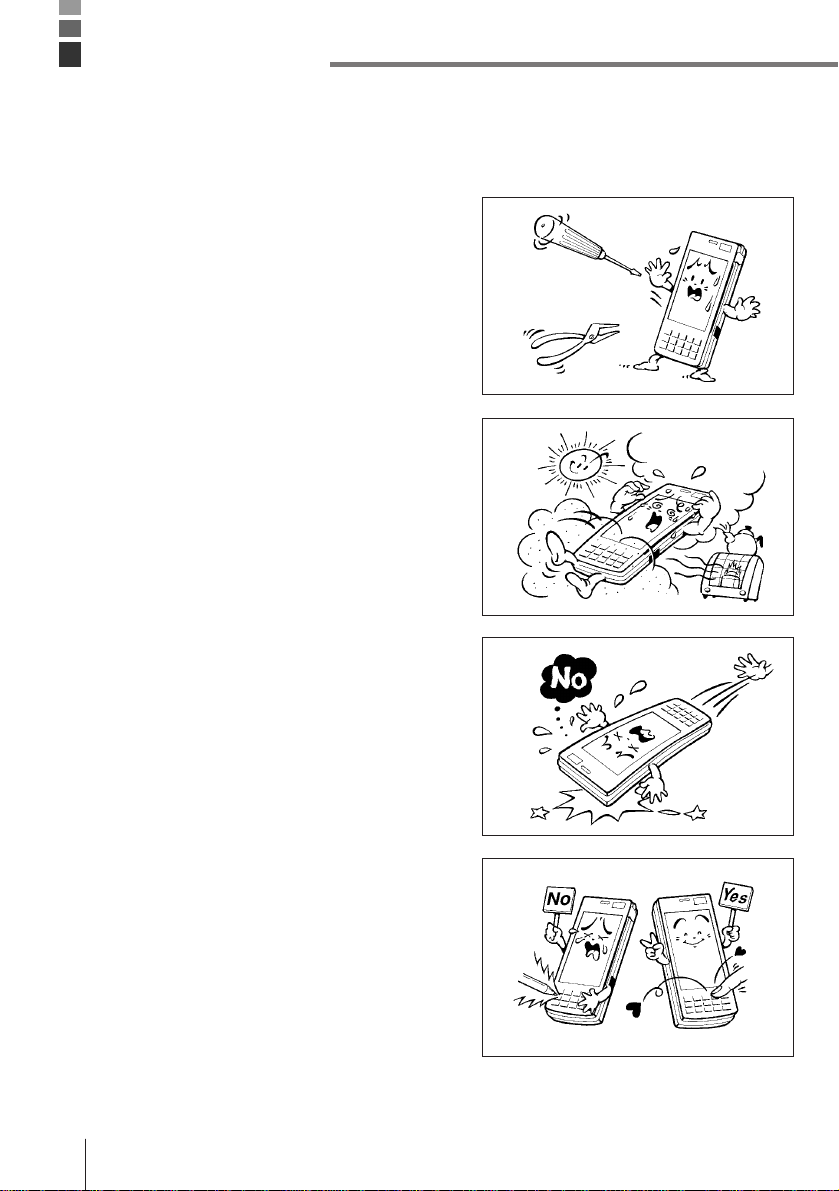
• This product is made of precision parts so do
not try to disassemble by yourself.
• Do not expose the Data Collector to excessive
heat or cold. Do not place it direct sunlight,
dusty or extremely humid areas. The utilization
of the power supply in moisture places is
forbidden. Do not leave the Data Collector on
hot places, such as car trunk or seats.
• Do not expose it to mechanical shocks,
especially during running programs, recording
or booting up because it can cause permanent
loss of data and damage to the LCD.
• Stroke keys must be pressed with care.
Use only the special touch panel pen for
working with the touch panel.
Do not apply excessive force or use sharp
objects for this purpose because in that way
you can damage the touch panel or internal
circuitry.
E-4
Page 5
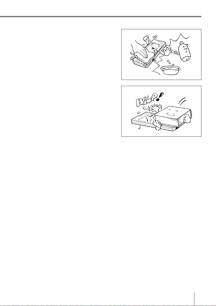
• Blow off dust with a blower brush or a soft
cloth.
No utilization of liquid- or spray-cleansing
agents is allowed. It may deform the keys or
the body of the Data Collector. The Data
Collector must not come in contact with
chemicals and gasoline.
• Do not place heavy objects on the Data
Collector.
Important! CASIO does not accept any responsibility for possible data loss caused
during, or connected with, usage of the Data Collector.
E-5
Page 6
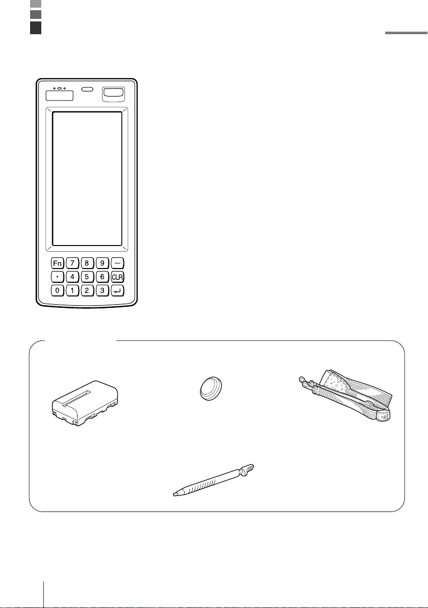
IT-2000 Series System Configuration
Accessories
• Lithium ion Battery
Pack
E-6
• Backup Lithium Battery
• Stylus
Placed to the right side of
the Data Collector
• Neck Strap
• Manual
Page 7
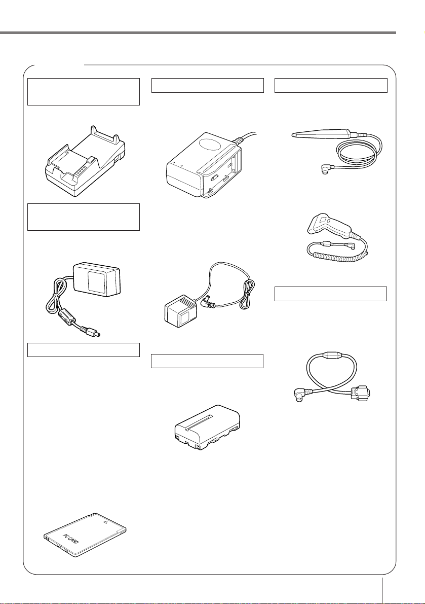
Options
Optical
Communication Unit
IT-2060IOE
AC adaptor for
Communication Unit
DT-825ADP-G
DT-825ADP-U
PC Cards
DT-635MC (SRAM 256KB)
DT-636MC (SRAM 512KB)
DT-637MC (SRAM 1MB)
DT-638MC (SRAM 2MB)
DT-9031BFMC
(FROM 4MB)
DT-9032BFMC
(FROM 6MB)
DT-9033BFMC
(FROM 10MB)
DT-9034BFMC
(FROM 20MB)
Optical
Charger
DT-9021CHGE
DT-9020ADP-G
DT-9020ADP-U
Lithium ion Battery Pack
DT-9023LI
Bar-code reader
DT-9650BCR
DT-9656BCR
Cable
DT-9689AX
(between Data Collector
and personal computer)
DT-881RSC
(modem-used)
DT-882RSC
(cross connection, male)
DT-883RSC
(cross connection, female)
DT-887AX
(AX-used, cross connection)
DT-888RSC
(Optical Communication
Unit-used)
E-7
Page 8
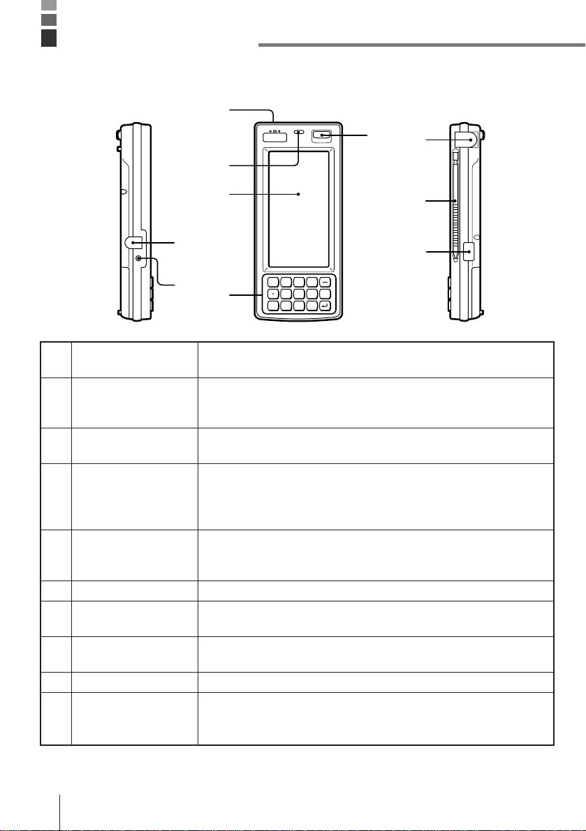
General Guide
Left Front Right
3
4
7
8
1 Charger connector
2 Charge indicator
3 Buzzer
4 Light sensor
5 LCD/Touch panel
6 Key pad
7 Power switch
8 RS-232C Interface
Connector
9 Stylus
10 Infrared interface
5
1
Fn
2
6
For connection of the charger to charge the lithium ion battery pack.
Protected by a cover that must be opened for connection.
Stays lit while the lithium ion battery pack is being charged, and goes
out after charging is complete. Lights momentarily when the charger
is connected even when the battery pack is charged.
Emits audible signals to confirm certain operations. Make sure that
buzzer holes are not blocked so signals can be heard.
Detects available light. This information is used to control the
backlight when the Data Collector is set up to automatically turn on
the backlight under low lighting conditions. For proper operation,
make sure this sensor is not blocked.
Display data during program execution and other operations. Also
provides touch panel keys for input by touching the screen with a
finger or the stylus that comes with the Data Collector.
10-key pad, execute key, and other keys.
Press to turn power on and off, or to restore power after operation of
auto power off.
For connection of a bar code reader or other external device.
Protected by a cover that must be opened for connection.
For touch panel operation.
Communication port for data exchange with the Optical
Communication Unit when exchanging data between two Data
Collectors.
789
456
0123
CLR
9
10
E-8
Page 9
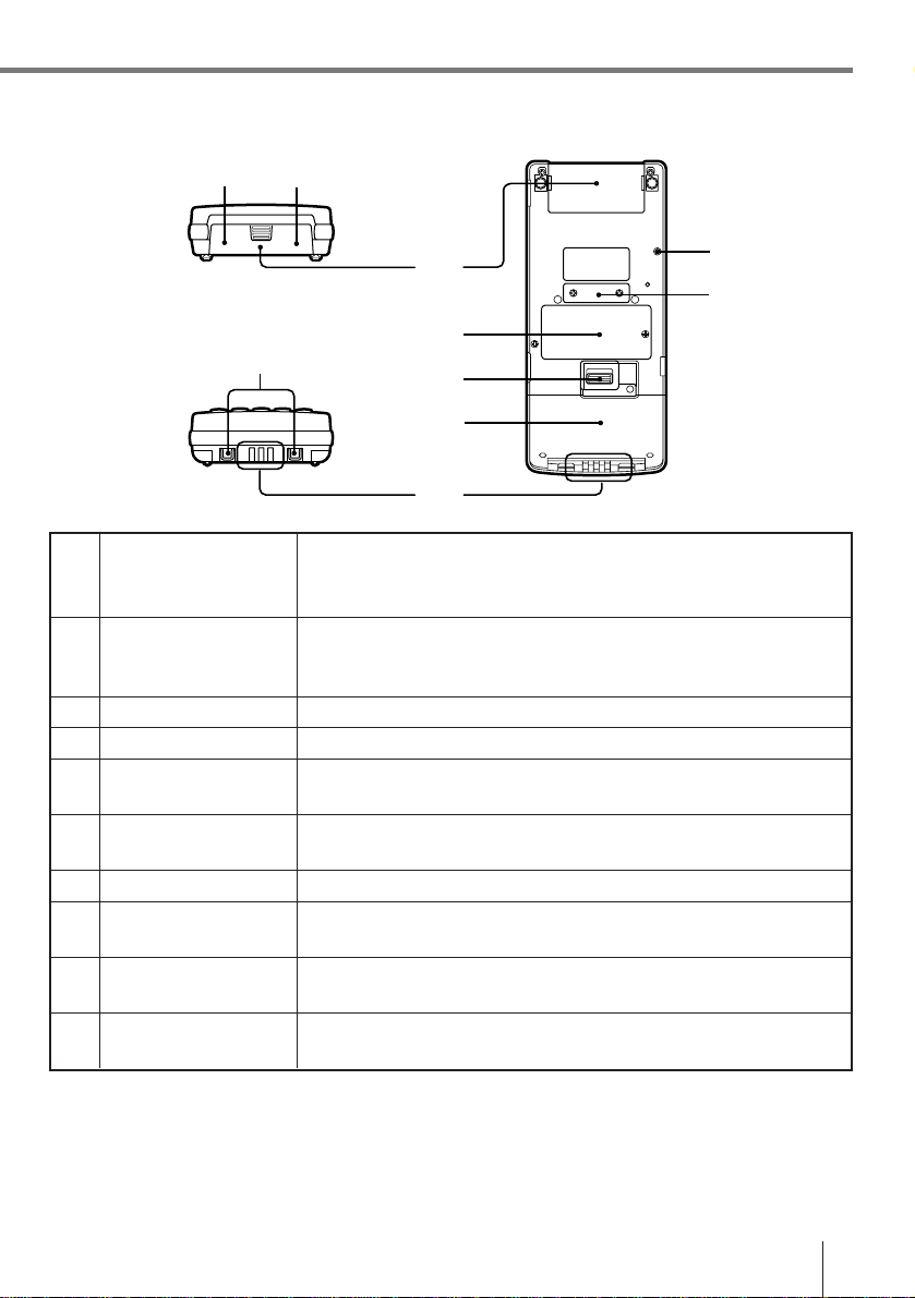
Top Back
11 12
Bottom
14
11 PC card lock button
(inside PC card slot
cover)
12 PC card eject button
(inside PC card slot
cover)
13 PC card slot cover
14 Neck strap bars
15 Charger connectors
16 Backup battery
compartment
17 Open button
18 Lithium ion battery
pack compartment
19 Initialize button
20 14-pin serial interface
connector
13
19
20
16
17
18
15
Locks optional PC card in place. Make sure this button is in the LOCK
position when using a PC card. The PC card is not detected by the
Data Collector when this button is in the LOCK release position.
Press this button (after opening the PC card slot cover and setting the
PC card lock button to lock release position) to eject a PC card
installed in the Data Collector.
Open when inserting or removing a PC card.
For connection of the neck strap.
These connectors mate with Optical Communication Unit connectors
to receive electrical power for charging of the lithium ion battery pack.
Houses the lithium battery used for memory backup.
Slide to open the battery pack cover.
Houses the lithium ion battery pack that is the Data Collector’s main
power supply.
Use a paper clip or other thin, pointed object to press this button to
launch the Data Collector’s system initialization routine.
For connection of future expansion options.
Note! Pressing the Initialize button clears all data and programs from memory.
Never press the Initialize switch unless absolutely necessary.
E-9
Page 10
Installing and Removing Batteries
Your Data Collector is powered by a rechargeable lithium ion battery pack and a lithium
backup battery.
Main power supply
See page E-19 for details on how to recharge the battery pack.
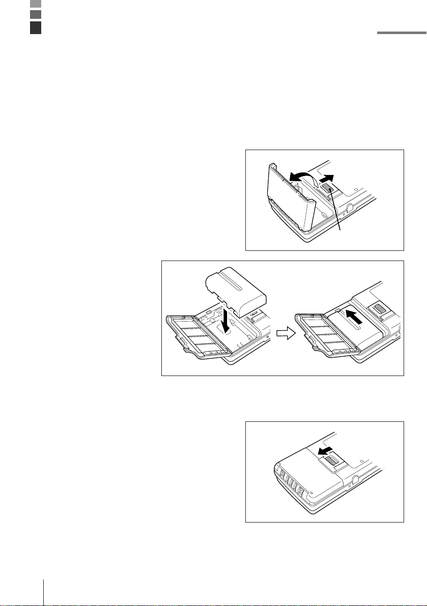
To install the battery pack
1 Slide the battery pack compartment open
button in the direction indicated by the arrow
in the illustration, and open the cover.
Open button
2 With the indentation of
the battery pack facing
up (so you can see it),
install the battery pack
into the compartment as
shown in the illustration.
Make sure that the
battery pack’s terminals
are facing in the correct
direction. Next, slide the
battery pack in the
direction shown in the
illustration so that it
locks into place.
3 Close the battery pack compartment cover.
Close the cover and then slide the open
button in the direction indicated by the arrow
to secure the cover in place.
Note that the battery pack will not supply
power correctly unless the battery pack
compartment cover is closed securely.
Double check to make sure that the cover of
your unit is closed correctly.
E-10
Page 11
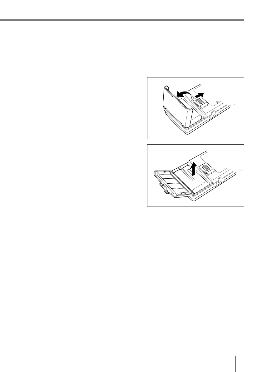
To remove the battery pack
Always make sure that Data Collector power is turned off before removing the battery pack.
Also, never remove the backup batteries while the battery pack is removed. Doing so will
cause all memory contents to be deleted.
1 Slide the battery pack compartment open
button in the direction indicated by the arrow
in the illustration, and open the cover.
2 Slide the battery pack in the direction shown
in the illustration and then remove it.
Important! • The power of the battery pack is depleted by testing prior to shipment
and by natural discharging during shipping and storage. Be sure to
use the procedures on page E-19 to charge the battery pack before
using the unit for the first time.
• A message appears on the LCD whenever battery pack power drops
below a certain level. Charge the battery pack as soon as possible
after the lower power message appears.
• Always make sure that the Data Collector is turned off before opening
the lithium ion battery pack compartment cover. The Data Collector is
designed to automatically turn off power whenever the battery pack
compartment cover opened. This can cause loss of memory data and
system malfunction when power is turned back on.
• Make sure that the battery pack never becomes shorted. A short can
cause damage to the battery pack.
• Repeated charges cause deterioration of the battery pack. If you find
that your battery pack does not provide enough operation even after
you bring it to a full charge, it probably means it is time to replace it.
• If you do not plan to use the Data Collector for a long time, protect
against running down the power of the backup batteries by fully
charging the battery pack.
E-11
Page 12
Installing and Removing Batteries
Backup batteries
The backup batteries protect the units memory contents whenever power from the main
battery pack is interrupted due to replacement of the battery pack, when the battery pack is
dead, etc.
Two lithium batteries are used for backup. The #2 backup battery is installed in the Data
Collector prior to shipment, but you must install the #1 backup battery that comes with the
Data Collector before using it for the first time.
Important! Dual backup batteries are employed in order to protect the #1 backup
battery from going dead. Note that memory contents cannot be
protected by the #2 backup battery alone.
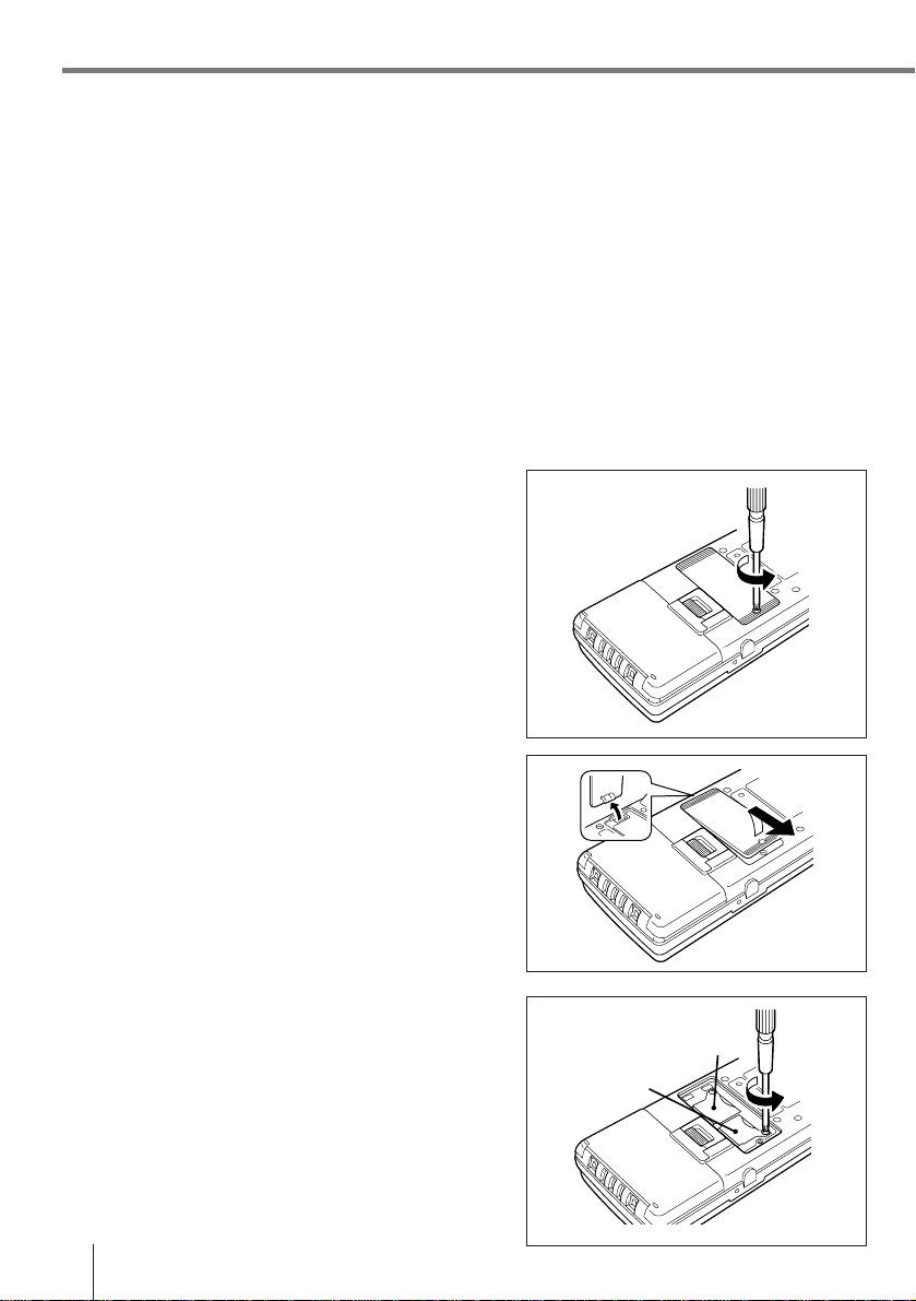
To install the #1 backup battery
1 Loosen the screw that secures the backup
battery compartment cover in place. The
cover is designed so the screws cannot be
removed from the holes in order to protect
against particles falling out of the screw
threads into the battery compartment.
2 Lift up the side of the cover indicated in the
illustration, and then slide the cover in the
direction indicated by the arrow. Make sure
you do not damage the tab on end of the
cover.
3 Loosen the screw that holds the #1 backup
battery holder in place, and remove the
holder. The cover is designed so the screws
cannot be removed from the holes in order to
protect against particles falling out of the
screw threads into the battery compartment.
E-12
#2 backup battery
#1 backup battery
Page 13
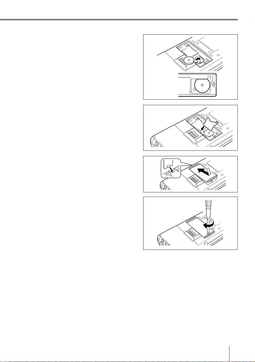
4 Wipe the surface of the lithium battery you
will install with a soft, dry cloth. Load the
battery into the Data Collector so that its
positive (+) side faces up (so you can see it).
5 Insert the tabs of the backup battery holder
into the slots provided, and secure it in place
with its screw.
6 Carefully replace the backup battery
compartment cover. Insert the tab of the
cover into the slot provided.
7 Secure the cover in place with its screw.
Important! • Whenever you remove the #1 backup battery and the main power
supply’s battery pack at the same time, memory contents are lost,
regardless of whether or not the #2 backup battery is installed. The #2
back-up battery alone does not protect memory contents.
• Never remove the #2 backup battery from the Data Collector.
• Always make sure that the + side of the lithium batteries are facing up
(so you can see them) when installing them into the Data Collector.
• Replace the #1 backup battery as soon as possible after the backup
battery replacement message appears on the Data Collector’s LCD.
Before replacing the #1 backup battery, always check to make sure
that the lithium ion battery pack’s power is not low first. Replacing the
#1 backup battery while the lithium ion battery pack’s power is low can
result is loss of all data stored in Data Collector memory.
E-13
Page 14

Position of the Keys
IT-2000 key part consist of 16 keys, including the power key.
Position of stroke keys
3
1
2
1 Function key
2 Number keys, decimal
3 Power key
4 Clear key
5 Execution key
Fn
0123
key, minus (–) key
E-14
789
456
CLR
4
5
Used for setting various program functions.
Combined with one or two of the ten keys (0 to 9).
Used for input of numbers. Press decimal point key to mark the
position of the decimal point.
Used for switching the power on/off.
Also, it is used for power on during the auto power off condition.
Clears’ previous input.
Confirms input and leads to the next step.
Page 15

Touch key panel
CALIBRATION
Carefully press on
the center of the
each cross by PEN.
1.SYSTEM MENU
2.RETRY
3.EXIT
The touch panel appears on the Data Collector’s LCD. Be sure to use only your finger or the
stylus that comes with the Data Collector to operate the touch panel.
Using the touch panel stylus
The touch panel stylus is attached to the right
side of the Data Collector.
Important! Use the procedure below to calibrate the touch panel whenever it
appears that it is misaligned on the LCD.
To calibrate the touch panel
1 Use a paper clip or some other thin, pointed
object to press the Initialize button on the
back of the Data Collector. This launches the
system initialization routine, which causes
the touch panel calibration screen shown
nearby to appear on the LCD.
2 Touch the center of each cross with the
stylus in the sequence indicated by the
arrow.
3 The touch panel calibration screen will be
cleared automatically after you touch all four
crosses.
E-15
Page 16

Position of the Keys
Parts and functions of the touch panel
4
1
Ctrl Del
Shift
2
Ext1BsExt2
3
afbcde
g
mrno
5
6
Ins
pq
7
8
9
10
lhi jk
11
sxtuvw
y ’z@[ ]
~
`{}
—
ˆ
” =()<>
+
–/,
1
Ctrl
Ext1
2
Ext2
3
Shift
4
5
Switches control mode. Press again to cancel it.
Switches in extended mode. Press again to cancel it.
Switches in extended mode. Press again to cancel it.
Select between the upper case and lowercase characters.
Moves the cursor up or scrolls the actual screen down.
SP
12
6
Ins
Del
7
Bs
8
9
10
11
SP
12
Important! The touch panel is supplied as a library for developing application
programs.
Before you use it, you need to link the library using an application
program.
Inserts characters.
Deletes character below the cursor.
Deletes the character on the left to the cursor.
Moves the cursor to the right.
Moves the cursor down or scrolls the actual screen up.
Moves the cursor to the left.
Inserts a space.
E-16
Page 17

Key display area patterns
Ctrl
AFBCDE
GLHI JK
MRNOP Q
SXTUVW
YZ
[
]
ˆ
—
/
You can change from the basic key pattern into the following patterns for character input.
Pattern 1:
Main mode
Ctrl Del
Shift
Ins
Ext1BsExt2
afbcde
g
mrnopq
sxtuvw
y
z@[ ]
`{}
—
” =()<>
+
– / ,
ˆ
Pattern 4:
Extended 1 mode
Main
Ext2
~
SP
Pattern 2:
Shift mode
Ctrl Del
Ext1BsExt2
AFBCDE
lhijk
’
GLHI JK
MRNOP Q
SXTUVW
YZ
!
” =()<>
+
Pattern 5:
Extended 2 mode
Main
Ext1
Shift
; :
%# &
– / ,
Pattern 3:
Control mode
Ins
/
$?
SP
You can set up a program to alter the contents of Extended 1 and Extended 2.
E-17
Page 18

System Initialization Routine
The system initialization routine is performed when you turn on the Data Collector for the
first time after purchasing it and whenever you press the Initialize button.
The following is the operational flow for the system initialization routine.
Press the power switch.
Self-diagnostic check of RAM and hardware,
followed by launch of MS-DOS.
Touch panel calibration screen and menu
appear, offering the following options.
Touch Panel Calibration
This procedure corrects
misalignment of input points
on the touch panel (page E-
15).
Press the Initialization button.
SYSTEM MENU EXIT
Launches the system
maintenance program,
which is used for installing
application programs and
other management tasks.
Exits the system
initialization routine without
calibrating the touch panel.
Important! Every time you turn on power, the system normally searches for an
application program in the following sequences: memory card, RAM
disk, F-ROM disk. The system initialization routine is launched only if
memory contents have been lost (due to both the lithium ion battery
pack and backup battery going dead) or if an application program
cannot be found.
E-18
Page 19

Charging the Battery Pack
The lithium ion battery pack is the Data Collector’s main power supply that provides power
for normal operations and memory backup. This means it is important to recharge or replace
the battery pack as soon as possible after the low battery message appears on the LCD.
Battery pack charging can be performed using any of the following options: DT-9021CHGE
Single Charger, DT-9020ADP-G/DT-9020ADP-U Charger.
To charge the battery pack
1 Plug the charger unit’s power cord into a
power outlet.
2 Slide the battery pack in the direction
indicated by the arrow in the illustration to
install it onto the charger unit. The charge
indicator (orange) lights at this time to
indicate that the battery pack is being
charged.
Charge indicator
3 After the charge indicator goes out (indicating
that charging is complete), slide the battery
pack in the opposite direction and remove it
from the charger unit.
Charging time
Charging time: approximately 1 hour and 40 minutes
Note! The above times may differ depending on the temperature in your area.
E-19
Page 20

Charging the Battery Pack
To charge battery packs using the Charger
1 Press the Data Collector’s Power switch to
turn off power.
2 Plug the charger into an electrical outlet, and
then attach the charger to charger connector
on the side of the Data Collector.
3 The Data Collector’s charge indicator lights
to indicate that the charge operation is being
performed. Charging is complete when the
charge indicator is no longer lit. It takes about
ten hours to achieve a full charge.
Important! • Removing the lithium ion battery pack from the Data Collector
consumes backup lithium battery power, which is used to retain data
in memory. This is no problem for short periods, but leaving the Data
Collector without a charged lithium ion battery pack for long periods
can cause the backup battery to go dead, resulting in loss of all
programs and data stored in Data Collector memory. Because of this,
we recommend that you keep charged battery packs on hand for use
while other battery packs are being charged.
• Long use of a lithium ion battery pack gradually shortens the amount
of operating time it provides after each charge. This is normal for the
lithium ion battery pack and does not indicate malfunction. If you find
that the amount of time provided by your battery pack is too short, it is
probably time to replace it with a new one.
• Never try to use the DT-9021CHGE or DT-9020ADP-G/DT-9020ADP-U
charger to charge any other type of battery pack.
• Avoid locations subject to vibration when performing the charge
operation.
• The battery pack discharges even when it is not loaded in the Data
Collector. Make sure you load the battery pack into the Data Collector
within at least one or two days after it is charged.
• It is recommended that a battery pack be removed from the DT9021CHGE or DT-9020ADP-G/DT-9020ADP-U charger within about 24
hours after full charge is attained.
E-20
Page 21

Attaching the Neck Strap
Length adjustment
Neck strap
Hooks
To attach the neck strap
Pulling back on the spring latches on the neck
strap hooks, attach the neck strap to the Data
Collector’s neck strap bars. Next, release the
latches to secure the neck strap in place.
To detach the neck strap
Pulling back on the spring latches on the neck
strap hooks, remove the neck strap to the Data
Collector’s neck strap bars.
Important! Never allow the Data Collector to swing around by the neck strap.
E-21
Page 22

Data Communication
You can exchange data between two Data Collectors or between a Data Collector and a
personal computer.
Exchanging Data Between Two Data Collectors
You can transfer applications and data to another Data Collector using the infrared interface.
The illustration below shows how two Data Collectors must be oriented for data
communication.
• Make sure that the infrared interfaces of both Data Collectors are not blocked.
• Communication is possible between two Data Collectors that are spaced from 0 (direct
contact) to 1 meter apart.
Exchanging Data with a Personal Computer
You can exchange data between a Data Collector and personal computer by connecting
them with an RS-232C cable.
E-22
Page 23

IT-2000’s Specifications
CPU: 32 bit CPU
RAM: 4 MB/8 MB
Display: VGA interface, 4-grayscale monochrome, 384 (V) x 194 (H) dots
Input: Touch key/touch panel method
Infrared: Interface: Conformed IrDA1.0 or IrDA1.1 Standard
Serial communication:
14-pin serial communication:
Other: Clock functions: second, minute, hour, day of the week, day, month, year
Power supply: Main power source: lithium ion battery pack
Operating temperature:
Dimensions (Approximate):
Weight (Approximate):
Display contrast adjusting: auto modifying
EL backlight (auto-off function, 20 - 1800 sec. in 20-second units), auto ON/OFF
16 stroke keys (including the power key)
Synchronization: Asynchronous (IrDA1.0)
Transfer rate: Conformed IrDA Ver. 1.0: ~ 115.5 Kbps
Interface: RS-232C level interface
Synchronous mode: Asynchronous
Transfer rate: 1,200 bps - 115.2 Kbps
Interface: RS-232C level interface
Synchronous mode: Asynchronous
Transfer rate: 1,200 - 9,600 bps
Full auto-calendar
Buzzer sound: 3-level volume possible (depending on the software)
Memory back-up battery:
Battery life: Lithium ion battery pack: 8 hours (stand-by)
Memory back-up battery: 2 weeks (DRAM 4 MB)
Battery checker: both for the main power battery and for the
Auto power-off function (1 - 15 minutes, setting in minutes of one)
–5°C - 50°C (23°F - 122°F)
85 (W) x 196 (L) x 30 (H) mm (3 11/32 x 7 11/16 x 1 3/16 inch)
430 g (15.1 oz)
Frame synchronization (IrDA1.1)
Conformed IrDA Ver. 1.1: ~ 4 Mbps
lithium batteries CR2032 (#1) and IVR2430 (#2)
back-up batteries.
Charger Specifications
Charger (DT-9021CHGE)
Power Supply: 100 V to 240 V, AC 50/60 Hz
Rated Input Capacitance: 40 VA (When used at 240 V)
Rated Output: 8.4 V DC, 1.4 A (During charge operation)
Approximate Charge time: 1 hour and 40 minutes
Dimensions (Approximate): 72 (W) x 43 (H) x 95 (D) mm (2 3/4 x 1 11/16 x 3 3/4 inch)
Weight (Approximate): 310 g (10.9 oz)
E-23
Page 24

IT-2060IOE Optional Optical Communication Unit
The IT-2060IOE Optional Optical Communication Unit makes it possible to quickly and
easily exchange system data and file data with a personal computer. The Optical
Communication Unit can also be used to charge the Data Collector’s lithium ion battery
pack. RS-232C cables (DT-881RSC, DT-882RSC, DT-883RSC, DT-887AX) are available to
connect the Optical Communication Unit to a personal computer.
General Guide
1
2
3
11
4
5
12
E-24
6
7
8
9
10
Page 25

1 RS-232C interface
connector
2 RS-422 interface
connector
3 AC adaptor jack
4 Connection detector
5 Infrared interface
6 Charge connectors
7 System status indicator
8 Communication status
indicator
9 Charge indicator
10 Power indicator
11 Power switch
12 DIP switches
For connection of an RS-232C cable to exchange system data and file
data with a personal computer.
For connection of a cable to daisy chain with another Optical
Communication Unit.
For connection of the AC adaptor, which supplies power.
Detects whether the Data Collector is correctly mounted onto the
Optical Communication Unit.
Non-contact communication port for data exchange with the Data
Collector.
These connectors mate with Data Collector connectors to provide
electrical power to the Data Collector.
Indicates the operational status of the system.
Off: System problem or failure to establish communication
with all Data Collectors mounted on daisy chained
Optical Communication Units.
On (green): Normal operation, communication established with all
Data Collectors.
Indicates the status of communications.
Off: No communication being performed.
Flashing (green): Communication being performed.
On (red): Optical Communication Unit connection
problem
Indicates the charge status of the Data Collector’s lithium ion battery
pack.
Off: No charging being performed.
On (red): Charging
Indicates the on/off status of the Optical Communication Unit and the
status of the connection between the Optical Communication Unit and
the Data Collector.
Off: Power off
On (red): Power on, no Data Collector mounted
On (green): Power on, Data Collector mounted
Turns power on and off.
Switches for configuring the Optical Communication Unit.
E-25
Page 26

IT-2060IOE Optional Optical Communication Unit
Connecting the Optical Communication Unit to a Power Source
Use only the specified AC adaptor to connect the Optical Communication Unit to an
electrical outlet. Be sure to connect the AC adaptor and turn on Optical Communication Unit
power before attempting to perform any data communication operation with the Data
Collector. The Optical Communication Unit supplies power to a Data Collector mounted on it.
To connect to a power source
1 Plug the AC adaptor into an electrical outlet.
2 After making sure that the power switch of
the Optical Communication Unit is turned off,
connect the AC adaptor to the AC adaptor
jack at the top of the Optical Communication
Unit.
3 After checking to make sure that the power of
the Optical Communication Unit and the
computer you are connecting to is turned off,
connect the RS-232C interface connector at
the top of the Optical Communication Unit to
the serial port of the computer using the
cable (DT-881RSC, DT-882RSC, DT883RSC, DT-887AX).
Keep the Optical Communication Unit’s RS232C interface connector cover whenever it
is not in use.
4 Turn on the Optical Communication Unit, and
its power indicator should light up red.
5 Mount the Data Collector onto the Optical
Communication Unit making sure that their
infrared interfaces align correctly with each
other. The power indicator of the Optical
Communication Unit should change to green
at this time.
• The system status indicator lights up green
when the system is operating correctly,
both during communication and
communication standby (when two or more
Optical Communication Units are daisy
chained).
• The communication status indicator
flashes green while communication is
being performed.
To electrical outlet
Power
switch (off)
Infrared
interfaces
Power switch
(on)
System status indicator
Communication status indicator
Charge indicator
Power indicator
E-26
Page 27

Using the Optical Communication Unit to Charge the Data Collector Battery Pack
1 Turn on the Optical Communication Unit, and
its power indicator should light up red.
Infrared
interfaces
2 Mount the Data Collector onto the Optical
Communication Unit making sure that their
charger connectors join securely with each
other.
If the Data Collector is turned off, it will turn
on automatically once a power connection is
established (this feature can be disabled by
software).
The power indicator of the Optical
Communication Unit should change to green
at this time, and the charge indicator should
light up red to indicate that the battery pack is
being charged.
Important! • Use the charger units designed for this product to charge the specified
battery packs only. Never try to charge another type of battery pack.
• The battery pack discharges even when it is not loaded in the Data
Collector. Make sure you load the battery pack into the Data Collector
as soon as possible after it is charged.
• Recharge the battery pack at a temperature between 0°C (32°F) and
40°C (104°F). Charging outside this range can cause leaking of battery
fluid and generation of heat by the battery. It can also reduce battery
performance and shorten battery life.
• To ensure proper battery pack charging, periodically wipe off the
charge connectors of the Optical Communication Unit and Data
Collector with a cotton swab or soft, dry cloth.
System status indicator
Communication status indicator
Charge indicator
Power indicator
Power
switch (on)
E-27
Page 28

IT-2060IOE Optional Optical Communication Unit
Daisy Chaining Optical Communication Units
An optional DT-888RSC 6-6 Pin Modular Cable can be used to daisy chain up to seven
Optical Communication Units. In this configuration, a personal computer can exchange data
with multiple Data Collectors simultaneously.
Daisy Chain Configuration
Connect the C-OUT terminal of the Optical Communication Unit that is closer to the host
computer to the C-IN terminal of the next Optical Communication Unit.
The following are the required DIP switch settings for Optical Communication Units in a
daisy chain configuration. See page E-29 for details on actually making DIP switch settings.
• The Optical Communication Unit furthest from the computer must be defined as the
“Terminator Unit in Linked Chain.”
• The Optical Communication Unit connected to the computer must be defined as the “Host
Computer Connection.”
• All other Optical Communication Units must be defined as “Intermediate Unite in Linked
Chain.”
E-28
Page 29

DIP Switch Settings
Flow Control
910
Off OFF OFF
X ON/X OFF ON OFF
RS/CS OFF ON
Use Special Software ON ON
Optical Communication Unit - Host
Computer Communication speed
67 8
2,400bps OFF OFF OFF
4,800bps ON OFF OFF
9,600bps OFF ON OFF
19,200bps ON ON OFF
38,400bps OFF OFF ON
57,600bps ON OFF ON
115,200bps OFF ON ON
* Communication speed can be set by
Data Collector overrides this setting.
Connection T ype
345
Data Collector - Optical Communication
Unit Communication Speed
12
38,400bps OFF OFF
115,200bps ON OFF
Host Computer OFF OFF ON (No linking)
Connection OFF (Linking)
Intermediate Unit
in Linked Chain
Terminator Unit
in Linked Chain
ON OFF OFF
ON OFF ON
Important! Other settings not shown here are used for special-purpose modes, and
should not be used.
E-29
Page 30

IT-2060IOE Optional Optical Communication Unit
IT-2060IOE Optical Communication Unit Specifications
Infrared Communication
Interface: Infrared
Conformed IrDA Ver. 1.0
Synchronization: Asynchronous
Baud Rate: 9,600/38,400/115,200 bps
RS-232C
Synchronization: Asynchronous
Baud Rate: 2,400 to 115,200 bps
Transmission Protocol: Full-duplex
RS-422
Synchronization: Asynchronous
Baud Rate: 9,600/38,400/115,200 bps
Output Power
Output: 12 V DC/500 mA
Power Supply
Source: Specified AC adaptor
Consumption Current: Approximately 600 mA (maximum during output of power for
charging)
AC Adaptor
Model: DT-825ADP-G Input: 230 V AC 50/60 Hz
Output: 12 V DC 1,400 mA
DT-825ADP-U Input: 120 V AC 50/60 Hz
Output: 12 V DC 1,400 mA
Functions
Infrared interface
RS-232C interface
RS-422 interface
Operating temperature
0°C - 40°C (32°F -104°F)
Dimensions
Approximately 110 (W) x 220 (D) x 80 (H) mm
(4 5/16 x 8 5/8 x 3 1/8 inch)
Weight
Approximately 370 g (13.0 oz)
E-30
Page 31

Handling Bar-Code Reader
Connect the bar-code reader to the Data Collector’s bar-code reader connector.
There are two models of bar-code reader: pen scanner DT-9650BCR, touch scanner DT9656BCR.
Connecting the bar-code reader
Turn the power on the Data Collector off.
1
Open the cover of the bar-code reader
connector.
2 Insert the plug of the bar-code reader into the
connector as shown on the picture.
Detaching bar-code reader
Turn the power on the Data Collector off. Unplug the bar-code reader connector.
Cover
Using a bar-code reader
<Pen scanner>
1 Bar code scanning angle
Reading power: 0.19 mm (for PCS value of 0.85)
Wand position Effective angle
Angle (up to 45 degrees)
E-31
Page 32

Handling Bar-Code Reader
2 Bar code scanning position
Start
Margin Margin
Correct Correct Correct
Correct Wrong Wrong
Stop
E-32
Wrong Wrong
Wrong
Page 33

<Touch scanner>
1 Bar-code touching angle (at read resolution 0.33mm, PCS 0.9)
How to hold the wand
non-contact distance (h) h = 0 ~ 10 mm
α = 0
β = 0
R = ∞
h
Angle between the bar-code and forward/backward inclined reading window (α)
1α = 0 ~ 30° (front part is inclined forward)
2α = 0 ~ 30° (back part is inclined backward)
h = 0
β = 0
1α 2α
R = ∞
The angle of inclination to the right/left (β)
β = 0 ~ 20°
h = 0
α = 0
β
Curve (R) R = 20 mm and above
h
R
R = ∞
β
(at read resolution 0.33)
h = 15 mm
α = 0
β = 0
h, α, β, R are commonly defined.
Position of bar-code must be in the center of the
reading window.
E-33
Page 34

Handling Bar-Code Reader
2 Bar-code touching angle
Margin Margin
Correct Correct Correct
Wrong Wrong Wrong
Wrong
<Sample bar-codes>
• These bar-codes are samples.
E-34
EAN CODE39
(Standard version)
EAN UPC
(Shorten version)
NW-7
Page 35

Bar Code Reader Specifications
DT-9650BCR Pen Scanner
Readable Codes: WPC (JAN, EAN, UPC), NW-7, CODE-39/93/128, ITF
Cable Length: Approximately 100 cm
Read Resolution: 0.125 mm min. (PCS value 0.85 min.)
Read Angle: 90 to 45 degrees
Scan Speed: 76 to 760 mm/second
Operating Temperature/Humidity:
–10 to 50°C (14 to 122°F)/15 to 90% RH
Dimensions: Approximately 147 (W) x 20.6 (D) x 12.5 (H) mm
(5 3/4 x 13/16 x 1/2 inch)
Weight: Approximately 75 g (2.6 oz)(including cable)
DT-9656BCR Touch Scanner
Readable Codes: WPC (JAN, EAN, UPC), NW-7, CODE-39/93/128, ITF
Cable Length: Approximately 76 cm (extended)
Read Resolution: 0.125 mm min. (PCS value 0.45 min.)
Non-contact Distance: 0 to 10 mm
Read Angle:
Forward/Back: 30 degrees
Left/Right: ±20 degrees
Rotating: ±25 degrees
Curved: R = 20 mm min. (with resolution of 0.33 mm)
Read Width: 67 mm
Operating Temperature/Humidity:
–10 to 50°C (14 to 122°F)/10 to 90% RH
Dimensions: Approximately 170 (W) x 75 (D) x 50 (H) mm
(6 11/16 x 3 x 2 inch)
Weight: Approximately 250 g (8.8 oz)(including cable)
E-35
Page 36

Using PC Cards
Your Data Collector supports use of a variety of PC cards (SRAM, FROM), which are
available as options. SRAM and FROM cards are available in different capacities, so you
can select the one that best suits your needs.
To load a memory card into the Data Collector
1 Turn off the Data Collector, turn it over, and
lift up the PC card slot cover while pressing
the projection as shown in the illustration.
2 Slide the PC card lock
button in the direction of
the arrow to release
LOCK and then slide the
end of the PC card
marked with
Data Collector. The
arrow should be facing
up (so you can see it).
into the
Make sure the mark is
facing up (so you can see
it). The location of the
mark differs according to
the card you are using.
3 Slide the PC card lock button to the LOCK
position.
E-36
Lock
button
Page 37

Important! • The PC card is not detected by the Data Collector when the PC card
lock button is in the LOCK release position. Sliding the PC card lock
button to the LOCK release position while the Data Collector is turned
on causes power to turn off automatically. Interrupted operations can
result in system malfunction when the Data Collector is turned back
on.
• Improper installation of a PC card can result in system malfunction and
inability to read the card.
To remove a card from the Data Collector
1 Turn off the Data Collector, turn it over, and
lift up the PC card slot cover while pressing
the projection.
2 Slide the PC card lock button in the direction
of the arrow to release LOCK and then press
the PC card eject button to eject the PC card.
Remove the PC card from the Data Collector.
Important! Forcing the PC card eject button without first sliding the PC card lock
button to the LOCK release position can damage the internal mechanism
of the Data Collector. Make sure you carefully follow the steps of the
procedures described above whenever inserting or removing a PC card.
PC card eject
button
E-37
Page 38

Operating Precautions
Data Collector
• Never try to remove the lithium ion battery pack while the Data Collector is turned on.
Doing so can cause data stored in memory to be deleted.
• Sudden temperature changes can cause condensation to form on the exterior of the Data
Collector’s case. Condensation can cause malfunction of the Data Collector, so wait until
the moisture dries completely before using it.
Bar Code Readers
• Handle bar code readers carefully to avoid damage to lenses. Should the lens of a bar
code reader become dirty or dusty, carefully remove it using a blower or a soft cloth.
• Grasp the connector plug whenever connecting or disconnecting a bar code reader. Make
sure you slide the plug straight into and straight out of the socket, and do not apply
excessive force left or right. Incorrect connection or disconnection of a bar code reader
plug can bend pins and cause other serious damage.
• Some bar codes may no be readable with a single pass because they are improperly
printed, soiled, etc. When this happens, repeat the read operation until a successful read
can be obtained.
PC Cards
• Do not drop or bend PC cards or otherwise subject them to strong impact or rough
handling.
• Take care to avoid letting dirt or dust get onto PC card connectors.
• Always replace a PC card into its soft case when storing it.
• Avoid exposing PC cards to direct sunlight for long periods.
• Never try to take PC cards apart.
E-38
Page 39

Notice
Congratulations upon your selection of the CASIO IT-2000 Data Collector.
Before using the IT-2000, note the following copyright restrictions that apply.
1 The operating system of this product includes proprietary intellectual property
(Microsoft® MS-DOS Operating System and Windows), which is subject to the following
terms and conditions.
2 The Operating System is licensed, not sold, to the user.
3 The user may NOT copy or decompile, reverse engineer, translate, disassembly, or
otherwise reduce the Operating System to a human understandable format.
4 The Operating System is licensed to the user “AS IS” with no warranty or representation,
either expressed or implied, regarding its merchantability, quality, functionality,
performance or fitness. It is the solely the responsibility of the user to determine the
software’s suitability for a particular purpose or use.
The user assumes all responsibility arising from the use of this Operating System.
5 CASIO COMPUTER CO., LTD. will in no event be liable for direct, indirect, special
consequential, or incidental damages resulting from any defect, error, or omission in the
Operating System, or for any other events including, but not limited to, any interruption of
service, loss of business, loss of profits or good will, legal action or any other
consequential damages.
E-39
Page 40

Page 41

Printed on recycled paper.
Imprimé sur papier recyclé.
Gedruckt auf wiederverwertetem Papier.
Imprimé au Japon
Printed in Japan
AB9906-0003503B
 Loading...