

Page 1
AP-38
INDEX
SEP. 2002
AP-38
ELECTRONIC KEYBOARD
Ver.2 Nov/ 2004
Page 2
CONTENTS
Safety Notice..................................................................................................... 1
Specifications ................................................................................................... 2
Block Diagram................................................................................................... 3
Diagnostic Program.......................................................................................... 4
Disassembly Instructions ................................................................................ 6
Circuit Description............................................................................................ 9
Printed Circuit Boards.................................................................................... 11
Exploded View ................................................................................................ 12
Parts List ......................................................................................................... 15
Schematic Diagrams ...................................................................................... 18
SAFETY NOTICE
CAUTION!
Danger of explosion if battery is incorrectly replaced.
Replace only with the same or equivalent type recommended
by the appliance manufacturer.Discard used batteries
according to manufacturer's instructions.
— 1 —
Page 3

SPECIFICATIONS
GENERAL
Models: AP-38/AP-38V
Keyboard: 88 piano keys (with touch response)
Polyphony: 64 notes, maximum
Tones: 16
Layer: Adjustable volume
Split: Split point, adjustable volume
Digital Effects: Reverb (8 types), Chorus (8 types), Brilliance
Demo Tunes: • Number of Tunes: 16
• Playback: Repeat (all tunes, one tune)
Song Memory: • Operations: Real-time recording, playback
• Number of Tracks: 2 (Track A, Track B)
• Capacity: Approximately 8,000 notes (total of 2 tracks)
• Memory Backup: Built-in lithium battery (Battery Life: Approximately 5 years)
Music Library: • Number of Tunes: 50
• Playback: All song repeat, specific song
• Part Off: L, R
Pedals: Damper, Soft, Sostenuto
Other Functions: • Metronome: Beat (6 types), Tempo (
• Touch Select: 3 types, off
• Transpose: 1 octave (F# to C to F)
• Tuning: A4 = 440 Hz ± 50 cents (adjustable)
• Temperament: 7 types
• Baroque pitch
MIDI: 16 multi-timbre receive
Input/Output: • Headphones: Stereo standard jacks × 2
• LINE OUT (R, L / MONO): standard jacks × 2
Output Impedance; 1.1 KΩ
Output Voltage; 1.3 V (RMS) MAX
• MIDI (OUT) (IN)
Speakers: ø 16 cm × 2, ø 5 cm × 2 (Output: 20 W + 20 W)
Power Supply: AP-38: 120V
AP-38V: 220-240V
Power Consumption: AP-38: 60W
AP-38V: 60W
Dimensions: • CELVIANO (without stand): 138.0 × 47.2 × 22.2 cm (54 3/8 × 18 5/8 × 8 3/4 inch)
• CELVIANO: 138.0 × 47.2 × 83.9 cm (54 3/8 × 18 5/8 × 33 1/16 inch)
Weight: •CELVIANO (without stand): approximately 39.0 kg (86.0 lbs)
• CELVIANO: approximately 51.0 kg (112.4 lbs)
= 30 to 255)
• Design and specifications are subject to change without notice.
• AP-38 has hardwired power cords.
• AP-38V has detachable power cords.
— 2 —
Page 4
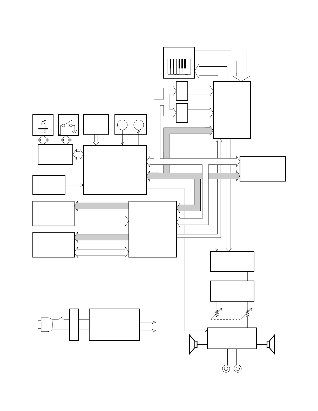
BLOCK DIAGRAM
LEDs Buttons
SW/LED
Controller
uPD65881GB
(LSI301)
Reset IC
RN5VD2BAA
IC 12
MIDI
IN
OUT
PEDAL
ANI0 ~ 2
M-IN M-OUT
CPU
uPD703107AGJ148UEN
LSI 6
Keyboard
IC 7
IC 8
CA1 ~ 4
3VD0 ~ 15
CA1 ~ 17
Mute
FI0 ~ 10
SI0 ~ 10
KC0 ~ 7
5VD0~7
5VD8~15
S00
LR00
CK00
LR01
Keyboard
Controller
TC190C020AF
LSI 1
RAM (128KB)
D442012AGYBB55XMJH
LSI 5
ROM (4MB)
MR27V6402G-0A3TP-3
LSI 2
RAM (128KB)
D442012AGYBB55XMJ1-1
LSI 4
SW400
T401
MA0 ~ 21
MD0 ~ 15
EA0 ~ 15
ED4 ~ 19
Power Supply
IC401: NJM78M05FA
IC402: NJM78M15FA
DSP
uPD914AGM-3ED
LSI 3
+5V
+15V
VDD
AVCC
CA1 ~ 6
3VD0 ~ 15
SYCK1
D/A Converter
PCM69BU/2K
D0
WCK
IC 2
Filter
IC 1, IC 5
Main
Volume
Power Amp.
LM4765T
IC403
SPSP
— 3 —
HEADPHONE
Page 5

DIAGNOSTIC PROGRAM
■Initial Setup
1. Connect an AC adaptor.
2. Connect a Sustain pedal.
3. Connect a MIDI cable (In-Out).
4. "Main" volume: MAX.
5. Turn the BRILLIANCE knob to the center.
6. Have the headphones ready.
NOTE: If there is no pedal or MIDI cable, pedal or MIDI check can be skipped.
■ How to start diagnostic program
1. Press the “POWER” button while pressing the “CHORUS key” and “GRAND PIANO1 key” buttons.
2. Release the “CHORUS” key and the “GRAND PIANO1” key.
All the LEDs turn on once.
■ Diagnostic program
1. RAM/ROM check
1 RAM/ROM check starts automatically after the diagnostic program is booted.
2 A confirmation tone of C4, E4 and G4 sounds after ROM/RAM check normally ends.
2. LED check
1 The following groups of 9 LEDs turn on one after another.
GROUP1: REVERB, CHORUS, GRAND PIANO1, GRAND PIANO2, ELEC PIANO1,
HARPSICHORD, PIPE ORGAN1, STRINGS1, CHIOR
GROUP2: ACOUSTIC BASS, VARIATION, SPLIT, SONG MEMORY, RECORD, TRACK A,
TRACK B, MUSIC LIBRARY, METRONOME
2 Press “CONTROL” button.
A confirmation tone of C4, E4 and G4 sounds.
3. SLIDER check
1 “PIPE ORGAN1” LED turns on.
2 Select “MELLOW”.
3 “GRAND PIANO 1” LED turns on.
4 Select “BRIGHT”
5 “VARIATION” LED turns on.
6 Turn the “BRILLIANCE” knob to the center.
7 Press “CONTROL” button.
A confirmation tone of C4, E4 and G4 sounds.
4. SWITCH check
1 Press “CONTROL” button.
A confirmation tone of C4 sounds.
2 Press “CONTROL” button.
A confirmation tone of C4 sounds.
3 Press “CONTROL” button.
A confirmation tone of C4 sounds.
4 Press “CONTROL” button.
A confirmation tone of C4 sounds.
5 Press “CONTROL” button.
A confirmation tone of C4 sounds.
6 Press “CONTROL” button.
A confirmation tone of C4 sounds.
7 Press “CONTROL” button.
A confirmation tone of C4 sounds.
8 Press “CONTROL” button.
A confirmation tone of C4 sounds.
9 Press “CONTROL” button.
A confirmation tone of C4 sounds.
0 Press “CONTROL” button.
A confirmation tone of C4 sounds.
A Press “CONTROL” button.
A confirmation tone of C4 sounds.
B Press “CONTROL” button.
A confirmation tone of C4 sounds.
C Press “CONTROL” button.
A confirmation tone of C4 sounds.
D Press “CONTROL” button.
A confirmation tone of C4 sounds.
E Press “CONTROL” button.
A confirmation tone of C4 sounds.
F Press “CONTROL” button.
A confirmation tone of C4 sounds.
G Press “CONTROL” button.
A confirmation tone of C4 sounds.
H Press “CONTROL” button.
A confirmation tone of C4 sounds.
I Press “CONTROL” button.
A confirmation tone of C4 sounds.
J Press “CONTROL” button.
A confirmation tone of C4 sounds.
A confirmation tone of C4, E4
and G4 sounds.
— 4 —
Page 6

5. PEDAL check
1 Press “CONTROL” button.
A confirmation tone of C4, E4 and G4 sounds.
2 Press “DAMPER” PEDAL.
A confirmation tone of C4 sounds.
“RECORD” LED turns on.
3 Press “SOSTENUTE” PEDAL.
A confirmation tone of E4 sounds.
“SONG MEMORY” LED turns on.
4 Press “SOFT” PEDAL.
A confirmation tone of G4 sounds.
“SPLIT” LED turns on.
6. PHONS JACK check
1 Press “CONTROL” button.
A confirmation tone of C4, E4 and G4 sounds.
2 “GRAND PIANO 1” LED turns on.
3 Plug the headphones into the left phone jack.
4 “GRAND PIANO 2” LED turns on.
5 Unplug the headphones.
6 “GRAND PIANO 1” LED turns on.
7 Plug the headphones into the right phone jack.
8 “GRAND PIANO 2” LED turns on.
9 Unplug the headphones.
7. MIDI check
1 Press “CONTROL” button.
A confirmation tone of C4, E4 and G4 sounds.
2 Press A4 key.
A confirmation tone of C4 sounds.
A confirmation tone of C4, E4 and G4 sounds twice.
8. Ending the diagnostic program
1 Press “POWER” button.
2 POWER LED turns off.
DIAGNOSTIC PROGRAM IS FINISHED.
— 5 —
Page 7
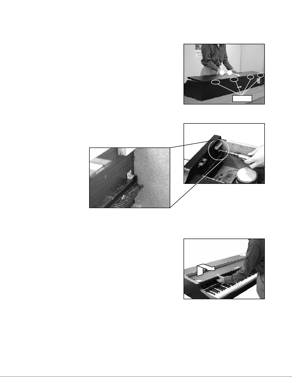
DISASSEMBLY INSTRUCTIONS
1. Removal of top board
1-1. Remove 8 screws affixing the top board on the back.
1-2. Slide the top board forward and remove it from the main unit.
2. Removal of keyboard cover
2-1. Lift up the keyboard cover full open position.
2-2. Unscrew the L-shaped stopper metal located on the inner
left corner.
1
2
Screws
2-3. Lift up the keyboard cover gear from the opening where
stopper metal is fixed, then remove the keyboard cover.
— 6 —
Page 8
3. Removal of console panel
Front cover screws
Bottom
Keyboard screws
3-1. Remove 2 connectors.
3-2. Lift the console panel and turn it over and remove the power switch, which is affixed by 2 screws.
Then remove the side panel.
Caution: Be careful not to scratch the side panels.
Screw
4. Removal of front cover
4-1. Remove 6 screws from the front end of the lower case.
4-2. Lift the front cover and remove the pilot lamp that is affixed
by 2 screws. Then remove the front cover.
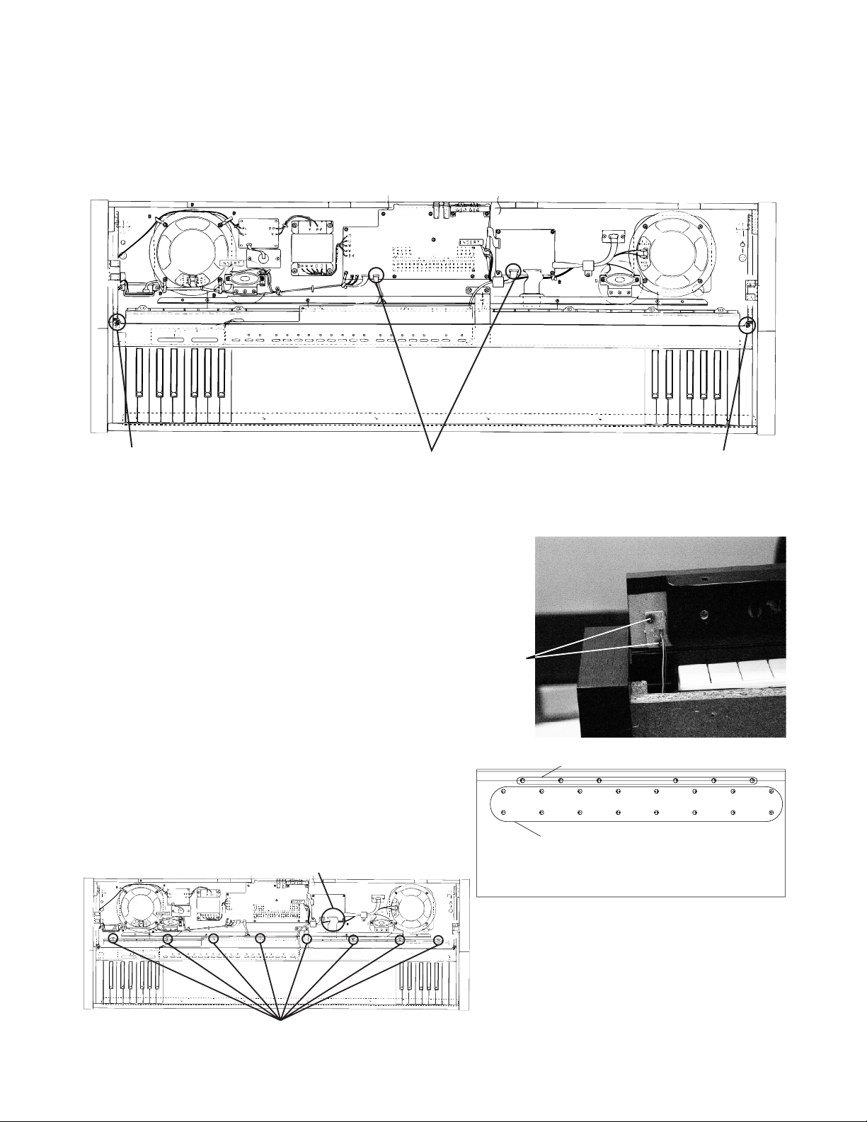
5. Removal of keyboard unit
5-1. Remove the connectors.
5-2. Remove 24 screws that affix the keyboard unit
(16 on the bottom of the case and 8 on the
keyboard unit).
5-3. Lift and remove the keyboard unit.
ScrewConnectors
screws
Connector
Keyboard screws
— 7 —
Page 9

6. Removal of keys
6-1. While plying the side partition plastics with tweezers, lift
the edge of the key toward front.
7. Removal of keyboard PCB
7-1. Lay the keyboard so that keyboard PCBs face upward.
7-2. Remove screws on keyboard PCBs (10 screws on PCBs
KY1M and KY3M, 12 screws on KY2M).
7-3. Unsolder the cable.
— 8 —
Page 10

KEY MATRIX
CIRCUIT DESCRIPTION
Second contact First contact
FI
2
KC0 KC1 KC2 KC3 KC4 KC5 KC6 KC7
FI0 A0 1 A0 # 1 B0 1 C1 1 C1 # 1 D1 1 D1 # 1 E1 1
SI0 A0 2 A0 # 2 B0 2 C1 2 C1 # 2 D1 2 D1 # 2 E1 2
EI1 F1 1 F1 # 1 G1 1 G1 # 1 A1 1 A1 # 1 B1 1 C2 1
SI1 F1 2 F1 # 2 G1 2 G1 # 2 A1 2 A1 # 2 B1 2 C2 2
FI2 C2 # 1 D2 1 D2 # 1 E2 1 F2 1 F2 # 1 G2 1 G2 # 1
SI2 C2 # 2 D2 2 D2 # 2 E2 2 F2 2 F2 # 2 G2 2 G2 # 2
FI3 A2 1 A2 # 1 B2 1 C3 1 C3 # 1 D3 1 D3 # 1 E3 1
SI3 A2 2 A2 # 2 B2 2 C3 2 C3 # 2 D3 2 D3 # 2 E3 2
FI4 F3 1 F3 # 1 G3 1 G3 # 1 A3 1 A3 # 1 B3 1 C4 1
SI4 F3 2 F3 # 2 G3 2 G3 # 2 A3 2 A3 # 2 B3 2 C4 2
1
KC
SI
LSI
HG52E35P
FI5 C4 # 1 D4 1 D4 # 1 E4 1 F4 1 F4 # 1 G4 1 G4 # 1
SI5 C4 # 2 D4 2 D4 # 2 E4 2 F4 2 F4 # 2 G4 2 G4 # 2
FI6 A4 1 A4 # 1 B4 1 C5 1 C5 # 1 D5 1 D5 # 1 E5 1
SI6 A4 2 A4 # 2 B4 2 C5 2 C5 # 2 D5 2 D5 # 2 E5 2
FI7 F5 1 F5 # 1 G5 1 G5 # 1 A5 1 A5 # 1 B5 1 C6 1
SI7 F5 2 F5 # 2 G5 2 G5 # 2 A5 2 A5 # 2 B5 2 C6 2
FI8 C6 # 1 D6 1 D6 # 1 E6 1 F6 1 F6 # 1 G6 1 G6 # 1
SI8 C6 # 2 D6 2 D6 # 2 E6 2 F6 2 F6 # 2 G6 2 G6 # 2
FI9 A6 1 A6 # 1 B6 1 C7 1 C7 # 1 D7 1 D7 # 1 E7 1
SI9 A6 2 A6 # 2 B6 2 C7 2 C7 # 2 D7 2 D7 # 2 E7 2
FI10 F7 1 F7 # 1 G7 1 G7 # 1 A7 1 A7 # 1 B7 1 C8 1
SI10 F7 2 F7 # 2 G7 2 G7 # 2 A7 2 A7 # 2 B7 2 C8 2
— 9 —
Page 11

BUTTON MATRIX
SC0 SC1 SC2 SC3
SI0 Control Reverb Chorus Piano1
SI1 Piano2 Ele Piano1 Harpsichord Pipe Organ1
SI2 Sirings1 Synth Pad1 Acoustic Bass Variation
SI3 Split Memory Record TrackA
SI4 TrackB Start/stop Song Metronome
LED MATRIX
LDH0 LDH1 LDH2 LDH3 LDH4 LDH5
LDL0 Reverb Piano2 Pipe Organ1 Acoustic Bass Memory TrackB
LDL1 Chorus Ele Piano1 Strings1 Variation Record Song
LDL2 Piano1 Hapshichord Synth Pad1 Split TrackA Metronome
— 10 —
Page 12

MAIN PCB JCM428-MA1M
PRINTED CIRCUIT BOARDS
Top view
Bottom view
— 11 —
Page 13

CABINET
12
2
47
46
17 18
15
16
13
13A
4
EXPLODED VIEW
48
1
3
13A
29 ~ 32
14
25 ~ 28
6
50
51
34
41
33
40
43
44
21
22
11
45
51
49
35
36
42
40
39
38
37
20
23
24
9
8
10
5
19
7
25 29 26 30 27 31 28 32
— 12 —
Page 14
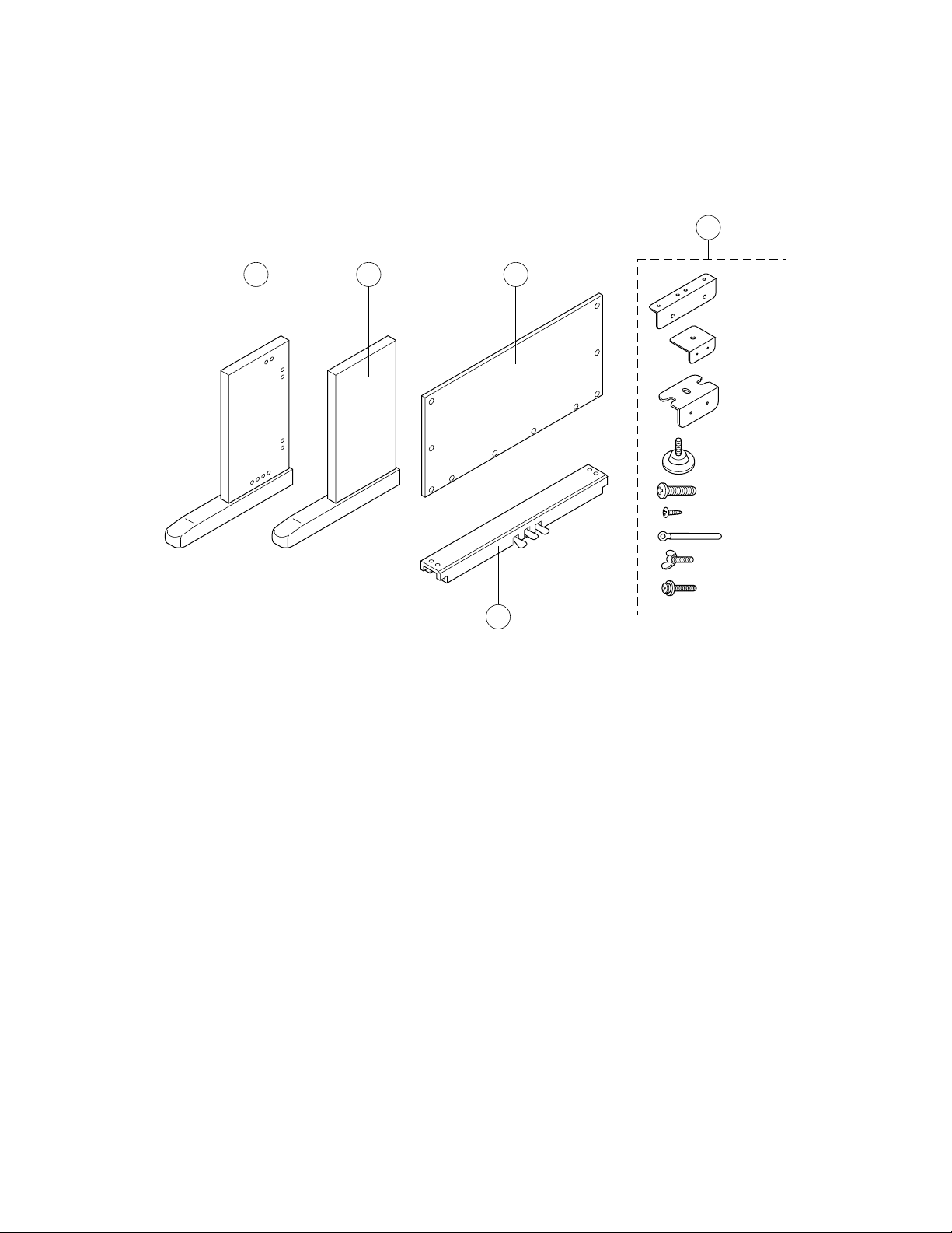
STAND
59
53 54 55
52
x2
x4
x2
x1
x4
x26
x2
x2
x4
— 13 —
Page 15

PARTS LIST
AP-38
Notes: This parts list does not include the cosmetic parts, which
parts are marked with item No. "R-X" in the exploded
view.
Contact our spare parts department if you need these
parts for refurbish.
1. Prices and specifications are subject to change without prior notice.
2. As for spare parts order and supply, refer to the
"GUIDEBOOK for Spare parts Supply", published
seperately.
3. The numbers in item column correspond to the same
numbers in drawing.
Page 16

N Item Code No. Parts Name Specification Q Price Code R Remark
MAIN PCB
N 1 1009 8415 PCB ASSY/M428-MA1M TK-RJM502154*001 1 DZ A
N LSI4,LSI5 1008 7835 LSI D442012AGYBB55XMJH 2 BI A
N LSI2 1008 7836 LSI MR27V6402G-0A3TP-N 1 BQ A
IC2 1000 8350 LSI PCM69BU/2K 1 BA A
LSI1 2012 5987 LSI TC190C020AF-001 1 BC A
N LSI6 1008 7837 LSI UPD703107AGJ133UEM 1 C C A
LSI3 1005 4502 LSI UPD914AGM-3ED 1 CK A
IC1 1004 7445 IC/M ON OLITHIC NJM2068MD(T1) 1 AC B
IC7, IC8 2105 6576 IC/C-MOS TC74LCX245FT(EL) 2 AF B
IC3 6932 4101 IC /MOS RN5RF33BA-TR 1 AN B
IC13 1004 7449 IC/MOS RN 5VD28 AA-TR 1 AC B
IC14 2105 5712 IC/L-MOS TC7S04FU(TE85L) 1 AB B
IC4 2105 6389 IC/L-MOS TC7SET04FU-TE85L 1 AD B
IC6 6930 9991 IC/L-MOS TC7SET08FU(TE85L) 1 AC B
IC12 2105 3696 IC/L-MOS TC7SH04FU-TE85L 1 AB B
IC11 2105 3773 IC/L-MOS TC7SH08FU-TE85L 1 AB B
IC5 2105 6083 IC/L-MOS TC7WU04FU(TE12L) 1 AD B
X3 1004 7438 OSC ILLATOR/CERAMIC CSTCR5M00G35-R0 1 AC C
X1 1004 7439 OSC ILLATOR/CERAMIC CSTCV16.00MXJ0C4-T 1 AC C
X2 1002 1357 OSC ILLATOR/CERAMIC DSX151GA-22.5792M 1 AS C
Q3 2250 1162 T RANSISTOR/CHIP 2SA1576AT106R 1 AA B
Q1 2259 2764 T RANSISTOR/CHIP 2SB1188T100Q 1 AB B
Q4 6930 0298 T RANSISTOR/CHIP 2SC4081T106R 1 AA B
Q2 2253 0715 T RANSISTOR/CHIP 2SD1664T100R 1 AA B
D4 1004 7442 DIODE/ZENER HZU2.7B2TRF 1 AA C
D1 2360 2856 DIODE/ZENER UDZTE-175.6B 1 AA C
D3 2390 2576 DIODE /CHIP SCHOTTKY RB501V-40TE-17 1 AB C
EF1/EF2 3025 1862 FILTER/EMI NFM51R00P206 2 AC B
BT1 1005 2229 LITHIUM BATTERY CR2032/1HF1 1 AG C
PS1 PCB
2 1005 4068 PCB ASSY/M437-PS1 TK-M341450*2 1 BO B 120V area
2 1005 4069 PCB ASSY/M437-PS1 TK-M341450*3 1 BP B 230V area
F400 1004 7505 FU SE 51MS050L 1 AC A 120V area
F400 1004 7508 FU SE 50T025H 1 AC A 230V area
PS2M PCB
N 3 1009 8414 PCB ASSY/M428-PS2M TK-RJM502159*001 1 DB B 120V area
N 3 1009 8934 PCB ASSY/M428-PS2M TK-RJM502159*002 1 DB B 230V area
IC403 1004 3418 IC/M ON OLITHIC LM4765T 1 BC B
IC405/IC406 2121 0072 IC/MONO LI THIC N JM2068DD 2 AD B
IC401 2114 5796 IC/M ON OLITHIC NJM 78M05FA 1 AE B
IC402 2114 5794 IC/M ON OLITHIC NJM 78M15FA 1 AE B
IC404 2114 1421 IC /PHOTOCOUPLER PC900VONSZX 1 AK B
Q401-Q405 2250 1592 TRANSISTOR 2SC1740STPR 5 AA B
Q406, Q407 1002 5042 TRANSISTOR 2SD1468STPR 2 AA B
D409-D412, 2315 3132 DIODE 1SS133T-77 6 AA C
D414, D415
D419 2390 3018 D IODE 1T2 1 AA C
D401-D404 1003 6785 DIODE 2A02B 4 AA C
D405-D408 1004 7403 DIODE 1N5401-EP 4 AA C
D416, D420 2390 2828 DIODE RB441Q-40T-77 2 AA C
D413 1003 8115 D IODE/ZENER MTZJT-775.6B 1 AA C
D417, D418 1004 7557 DIODE/ZENER MTZJT-778.2B 2 AA C
J402 3612 0789 JACK YKB21-5010 1 AC A
J403 3612 0584 JACK YKB21-5012 1 AD A
J401 3501 4816 JACK/DIN YKF51-5051 1 AH B
F401 1005 4029 FU SE 50T010H 1 AC A 230V area
F401 1005 2231 FU SE 51MS010L 1 AC A 120V area
F402,F403 1005 4030 FUSE 50T040H 2 AC A 230V area
F402,F403 1005 2230 FUSE 51MS040L 2 AC A 120V area
Notes : Q - Quantity per unit
R - Rank
— 15 —
Page 17

N Item Code No. Parts Name Specification Q Price Code R Remark
PS3M PCB
N 4 1009 8420 PCB ASSY/M428-PS3M TK-RJM502160*001 1 D Z B
J404, J405 1004 7514 JACK/PHONE YKB22-5078 2 AG A
PS4M PCB
N 5 1009 8417 PCB ASSY/M428-PS4M TK-RJM502161*001 1 BC B
D400 2370 1417 LED SLP-135B-51 1 AA B
CONSOL PCB
N 6 1009 8418 PCB ASSY/M428-CN1M,CN2M RJM502165*001 1 CR B
LSI301 6932 4293 LSI UPD65881GK-062-9ET 1 AT A
Q307-Q309 1004 7532 TRANSISTOR 2SC5720(TPE4) 3 AA B
Q301-Q306 1004 7535 TRANSISTOR RN2205(TPE4) 6 AA B
D301-D318 2370 1416 LED SLZ-190B-03-T2 18 AA B
X301 2529 2032 OSCILLATOR/CERAMIC CSB1000J 1 AC C
VR301 2765 0280 VOLUME EWA-NAXCH1B14 1 AI B
VR302 2765 2187 VOLUME EWA-NFECH1B54 1 AG B
KEYBOARD PCB
D701-D876 2315 3132 DIODE 1SS133T-77 176 AA B
7 6928 5460 PCB ASSY/M887T-KY1M M240951A*1 1 BO C
8 6928 5470 PCB ASSY/M887T-KY2M M240952*1 1 BT C
9 6928 5480 PCB ASSY/M887T-KY3M M241019A:1 1 BM C
MAIN CASE UNIT
N 10 1009 8935 MAIN CASE ASSY TK-RJM502025*001 1 DO X
N 11 1009 8936 COVER ASSY/KEYBOARD TK-RJM502084*001 1 DH X
N 12 1009 8937 BOARD ASSY/FRONT TK-RJM502023*001 1 DA X
13 1004 7602 SPEAKER S16J75A 2 BL B
13A1004 7589NETM441191-1 2 AD C
14 3831 1075 SPEAKER S05JH37A 2 AR B
15 1005 4031 TRANSFORMER TE-427-1M1 1 C W B 120V area
16 1005 4032 TRANSFORMER TE-427-2M1 1 C W B 230V area
17 1005 4071 CORD ASSY/AC TK-M341449*2(M427) 1 AW C 120V area
18 1005 4067 2P AC INLET ASSY TK-M341448*1 1 AT B 230V area
N 19 1009 8938 F BRD ASSY TK-RJM502089*001 1 DI X
KEYBOARD UNIT
20 1004 6083 KY ASSY M141175*1 TK(MLMP2) 1 EM B
N 21 1009 6229 CHASSIS SUB ASSY M140831*003V09 1 CW C
22 6928 4470 RUBBER/CONTACT M240957-2 1 AE A
23 6928 4480 RUBBER/CONTACT M240958-2 6 AH A
24 6928 4490 RUBBER/CONTACT M240959-2 1 AH A
25 1005 2296 HAMMER ASSY/WHITE KEY ( R ) M341434*1 TK(MLMP) 13 BH B
26 1005 2297 HAMMER ASSY/WHITE KEY ( G ) M341435*1 TK(MLMP) 13 BH B
27 1005 2298 HAMMER ASSY/WHITE KEY (BK) M341436*1 TK(MLMP) 13 BH B
28 1005 2299 HAMMER ASSY/WHITE KEY (BL) M341437*1 TK(MLMP) 13 BH B
29 1005 2300 HAMMER ASSY/BLACK KEY ( R ) M341438*1 TK(MLMP) 9 BH B
30 1005 2301 HAMMER ASSY/BLACK KEY ( G ) M341439*1 TK(MLMP) 9 BH B
31 1005 2309 HAMMER ASSY/BLACK KEY (BK) M341440*1 TK(MLMP) 9 BH B
32 1005 2310 HAMMER ASSY/BLACK KEY (BL) M311441*1 TK(MLMP) 9 BH B
33 6927 4030 BLACK KEY M140784-1 36 AG B
N 34 1008 3392 WHITE KE Y/C M140783-007V04 7 AF B
N 35 1008 3394 WHITE KE Y/D M140785-007V04 7 AG B
N 36 1008 3408 WHITE KEY/E M140786-007V04 7 AF B
N 37 1008 3411 WHI TE KEY/F M140787-007V04 7 AF B
N 38 1008 3452 WHITE KEY/G M140788-007V04 7 AF B
N 39 1008 3454 WHITE KEY/A M140789-007V04 7 AF B
N 40 1008 3456 WHITE KEY/B M140790-007V04 8 AF B
N 41 1008 3475 WHITE KEY/SA M140792-007V04 1 AJ B
N 42 1008 3473 WHI TE KEY/SC M140791-007V04 1 AJ B
43 6927 4011 CAP GUIDE/WHITE KEY M340958-1 13 AE C
44 6927 4020 CAP GUIDE/BLACK KEY M340959-1 36 AA C
Notes : Q - Quantity per unit
R - Rank
— 16 —
Page 18

N Item Code No. Parts Name Specification Q Price Code R Remark
CONSOLE PANEL ASSY
N 45 1009 8421 CONSOLE PANEL ASSY TK-RJM502032*001 1 CX X
46 6924 5260 BUTTON/POWER M340318-1 1 AA B
N 47 1009 8419 POWER SW ITCH ASSY TK-M341447*003V01 1 AU B
48 6919 3240 KNOB/SLIDE M311405-1 2 AB A
SW301-SW320 1004 7536 SW ITCH/TACT SKQNAED010 20 AA A
N 49 6927 7140 TAC T BUTTON 425 M340978-1 4 AA B
N 50 6927 7150 TAC T BUTTON 425 M340978-2 7 AB B
N 51 6927 7160 TAC T BUTTON 425 M340978-3 2 AA B
AC CORD
56 1004 5706 CORD-SET EC2NC-M001A 1 AM C OTERS: 230V
57 1004 5707 CORD-SET BC2NC-M001A 1 BD C UK: 230V
STAND
N 52 1009 8939 ST-PDL-ASSY2 TK-RJM502011*001 1 DK C
N 53 1009 8940 ST-BRD-L-ASSY TK-RJM502010*001 1 CO C
N 54 1009 8941 ST-BRD-R-ASSY TK-RJM502046*001 1 CO C
N 55 1009 4129 ST-BRD-BK-M428 RJM501890-001v01 1 CO C
N 58 1009 8942 MST -ASSY TK-RJM502108*001 1 CP C
N 59 1009 8423 ACC-BAG-ASSY TK-RJM502026*001 1 CR C
Notes : Q - Quantity per unit
R - Rank
— 17 —
Page 19

MAIN PCB JCM428-MA1M
SCHEMATIC DIAGRAMS
— 18 —
Page 20

I/O and POWER SUPPLY(120V) PCBs JCM428-PS2M/PS3M/PS4M
— 19 —
Page 21

I/O and POWER SUPPLY(230V) PCBs JCM428-PS2M/PS3M/PS4M
— 20 —
Page 22

CONSOLE PCBs JCM428-CN1M/CN2M
— 21 —
Page 23

KEYBOARD PCB JCM887T-KT1M
— 22 —
Page 24

KEYBOARD PCB JCM887T-KT2M
— 23 —
Page 25

KEYBOARD PCB JCM887T-KT3M
— 24 —
Page 26

Ver.1 : Sep. 2003
Addition of a diagnostic program item
Ver.2 : Nov. 2004
Correction of the EXPLODEDE VIEW (page 12) and PART LIST (page 16)
CASIO TECHNO CO.,LTD.
Overseas Service Division
6-2, Hon-machi 1-Chome
Shibuya-ku, Tokyo 151-8543, Japan
 Loading...