

AP-25/28
INDEX
APR. 2001
AP-25/28
ELECTRONIC KEYBOARD
CONTENTS
Safety Notice...................................................................................... 1
Specifications .................................................................................... 2
Block Diagram ................................................................................... 3
Replacement of the Keyboard.......................................................... 4
Circuit Description ............................................................................ 6
Exploded View ................................................................................... 7
Parts List ............................................................................................ 9
Schematic Diagrams ....................................................................... 13
SAFETY NOTICE
CAUTION!
Danger of explosion if battery is incorrectly replaced.
Replace only with the same of equivalent type recommended
by the appliance manufacturer.Discard used batteries
according to manufacturer's instructions.
— 1 —

SPECIFICATIONS
GENERAL
Models: AP-25/AP-25V/AP-28/AP-28V
Keyboard: 88 piano keys (with touch response)
Polyphony: 64 notes, maximum
Tones: 8
Digital Effects: Reverb (4 types), Chorus
Demo Tunes: • Number of Tunes: 8
• Playback: Repeat (all tunes, one tune)
Memory: • Operations: Real-time recording, playback
• Capacity: Approximately 2,500 notes (one song)
• Memory Backup: Built-in lithium battery (Battery Life: 5 years)
Pedals: AP-25/AP-25V: Damper, Soft/Sostenuto (Selectable)
AP-28/AP-28V: Damper, Soft, Sostenuto
Other Functions: • Metronome: Beat (6 types), Tempo ( = 30 to 255)
• Touch Select: 3 types, off
• Transpose: 1 octave (F# to C to F)
• Tuning: A4 = 440Hz ±50 cents (adjustable)
MIDI: 16 multi-timbre receive
Input/Output: • Headphones: Stereo standard jacks × 2
Output Impedance: 470Ω
Output Voltage: 18V (RMS) MAX
• MIDI (OUT) (IN)
Speakers: ø 12cm × 2 (Output: 20 W + 20 W)
Power Supply: AP-25/AP-28: 120V
AP-25V/AP-28V: 220-240V
Power Consumption: AP-25/AP-28: 60W
AP-25V/AP-28V: 60W
Dimensions: • CELVIANO (without stand): 137.0 × 42.5 × 19.0 cm (53 15/16 × 16 3/4 × 7 1/2 inch)
• CELVIANO: 139.0 × 47.0 × 81.0 cm (54 3/4 × 18 1/2 × 31 7/8 inch)
Weight: •CELVIANO (without stand): approximately 34 kg (74.8 lbs)
• CELVIANO: approximately 44 kg (96.8 lbs) (AP-25/AP-25V)
approximately 44 kg (96.8 lbs) (AP-28/AP-28V)
• Design and specifications are subject to change without notice.
• AP-25 and AP-28 have hardwired power cords.
• AP-25V and AP-28V have detachable power cords.
— 2 —
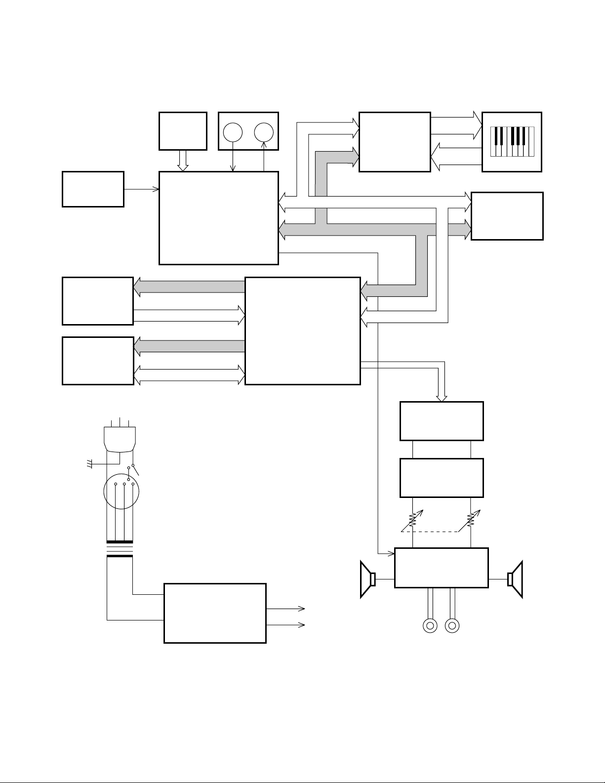
BLOCK DIAGRAM
Reset IC
RN5VD2BAA
IC 13
ROM (4MB)
MR27V3202E-81MA
LSI 2
RAM (128KB)
CY62126BVLL-55ZI
LSI 4
PEDAL
ANI0 ~ 2
CPU
uPD703107AGJ103UEN
LSI 6
MA0 ~ 20
MD0 ~ 15
EA0 ~ 15
ED4 ~ 19
MIDI
IN
OUT
M-IN M-OUT
uPD914AGM-3ED
DSP
LSI 3
3VD0 ~ 15
CA1 ~ 4
Keyboard
Controller
TC190C020AF
LSI 1
3VD0 ~ 15
CA1 ~ 16
Mute
CA1 ~ 5
3VD0 ~ 15
KC0 ~ 7
FI0 ~ 10
SI0 ~ 10
SYCK
BCK
WCK
Keyboard
RAM (128KB)
CY62126BVLL-55ZI
LSI 5
Voltage
Selector
Power Switch
Power
Transformer
T101
Power Supply
IC401: NJM78M05FA
IC402: NJM78M15FA
+5V
+15V
VDD
AVCC
D/A Converter
PCM69BU/2K
IC 2
Filter
IC1, IC405, IC406
Main
Volume
Power Amp.
LM4765T
IC403
HEADPHONE
SPSP
— 3 —
REPLACEMENT OF THE KEYBOARD
Guide
White key
Grease
Grease
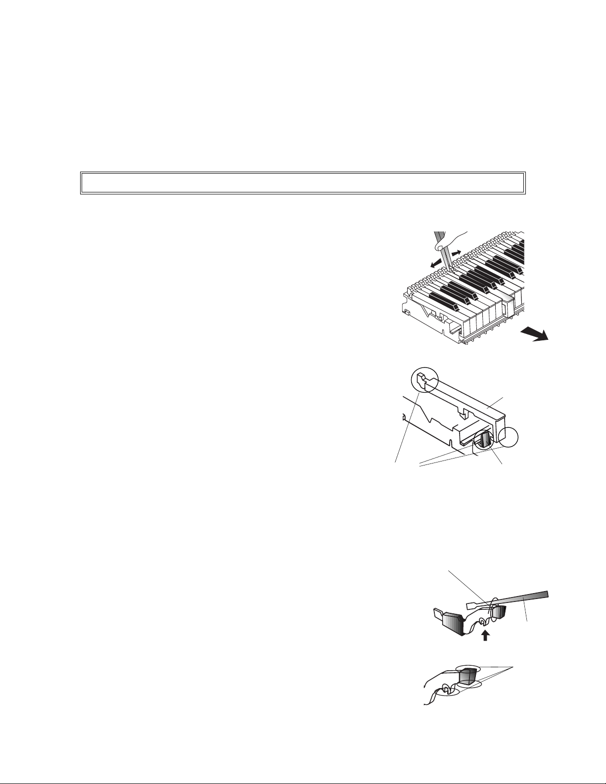
1) Replacement of the white key / black key
2) Replacement of the hammer
3) Replacement of the contact rubber
4) Other precauions
When the the keyboard needs to be replaced, make sure to check the key touch before replacing it.
1) Replacement of the White key / Black key
1. Expand the rear end of the white key/black key by a pair of
tweesers and slide it forward horizontally.
2. Apply proper amount of grease to the inside of the Guide and
the front end of the key as well as the rear end of the key.
* Take extra care of the quantity of the grease, which can easily
change the key touch.
* It is recommended to refer to the quantity of the grease which
is applied to the neighboring keys.
3. After replacing the key, put the front end of the key back into the
Guide and slide it backward horizontally.
* T ake extra care not to make any scratches in the inside of the
front end of the key and the Guide.
2) Replacement of the Hammer
1. If no jig is available when disassembling, use a driver and a big clip. Then,
lift the hammer up and remove it like a lever.
Clip
Driver
2. Apply the grease (G501) thinly to the top and bottom of the front end as
well as the fulcrum of the hammer.
* It is recommended to refer to the quantity of the grease which is applied
to the other hammers when disassembling.
— 4 —
Jig (lumber)
10 mm × 10 mm
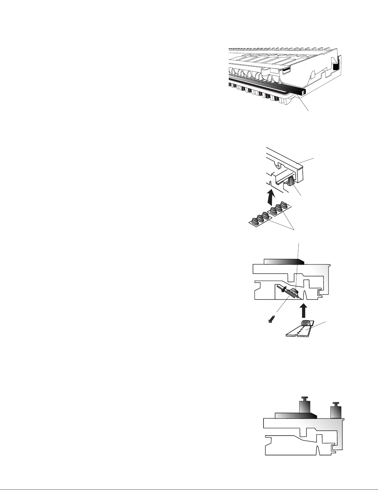
3) Replacement of the contact rubber. (A Jig is necessary)
Since the contact rubber is replaced with the keyboard (both
white keys and b lack ke ys) turned upside down, a jig is necessary
to prevent from v arious troubles caused b y the fact that the keys
are pushed down.
Precautions when replacing the contact rubber
1. Make sure that the keys are NOT pushed down.
2. Make sure that the contact rubber is attached to the frame in the right
position.
White key
3. When assembling, take extra care that the contact rubber can often
be slipped or twisted at the ends of the rubber itself and the PCB.
4. Make sure that the screw is fixed vertically to the PCB since the key
PCB is fixed at an angle (see the right figure).
5. The key touch may change if the abov e precauions are not followed.
Screw
Guide
Contact rubber
4) Other precautions
Initial load inspection of the keyboard
1. Check if the keys go down with the load put on them (100g for the white key and 105g for the black key).
PCB
Maintenance of the keyboard unit
1. Never keep the keyboard unit upside down, since the contact rubber may
be stuck to the PCB.
— 5 —
105 g
100 g

KEY MATRIX
CIRCUIT DESCRIPTION
Second contact First contact
FI
2
KC0 KC1 KC2 KC3 KC4 KC5 KC6 KC7
FI0 A0 1 A0 # 1 B0 1 C1 1 C1 # 1 D1 1 D1 # 1 E1 1
SI0 A0 2 A0 # 2 B0 2 C1 2 C1 # 2 D1 2 D1 # 2 E1 2
EI1 F1 1 F1 # 1 G1 1 G1 # 1 A1 1 A1 # 1 B1 1 C2 1
SI1 F1 2 F1 # 2 G1 2 G1 # 2 A1 2 A1 # 2 B1 2 C2 2
FI2 C2 # 1 D2 1 D2 # 1 E2 1 F2 1 F2 # 1 G2 1 G2 # 1
SI2 C2 # 2 D2 2 D2 # 2 E2 2 F2 2 F2 # 2 G2 2 G2 # 2
FI3 A2 1 A2 # 1 B2 1 C3 1 C3 # 1 D3 1 D3 # 1 E3 1
SI3 A2 2 A2 # 2 B2 2 C3 2 C3 # 2 D3 2 D3 # 2 E3 2
FI4 F3 1 F3 # 1 G3 1 G3 # 1 A3 1 A3 # 1 B3 1 C4 1
SI4 F3 2 F3 # 2 G3 2 G3 # 2 A3 2 A3 # 2 B3 2 C4 2
1
KC
SI
LSI
HG52E35P
FI5 C4 # 1 D4 1 D4 # 1 E4 1 F4 1 F4 # 1 G4 1 G4 # 1
SI5 C4 # 2 D4 2 D4 # 2 E4 2 F4 2 F4 # 2 G4 2 G4 # 2
FI6 A4 1 A4 # 1 B4 1 C5 1 C5 # 1 D5 1 D5 # 1 E5 1
SI6 A4 2 A4 # 2 B4 2 C5 2 C5 # 2 D5 2 D5 # 2 E5 2
FI7 F5 1 F5 # 1 G5 1 G5 # 1 A5 1 A5 # 1 B5 1 C6 1
SI7 F5 2 F5 # 2 G5 2 G5 # 2 A5 2 A5 # 2 B5 2 C6 2
FI8 C6 # 1 D6 1 D6 # 1 E6 1 F6 1 F6 # 1 G6 1 G6 # 1
SI8 C6 # 2 D6 2 D6 # 2 E6 2 F6 2 F6 # 2 G6 2 G6 # 2
FI9 A6 1 A6 # 1 B6 1 C7 1 C7 # 1 D7 1 D7 # 1 E7 1
SI9 A6 2 A6 # 2 B6 2 C7 2 C7 # 2 D7 2 D7 # 2 E7 2
FI10 F7 1 F7 # 1 G7 1 G7 # 1 A7 1 A7 # 1 B7 1 C8 1
SI10 F7 2 F7 # 2 G7 2 G7 # 2 A7 2 A7 # 2 B7 2 C8 2
— 6 —

CABINET
EXPLODED VIEW
45
39
43
24
13
11
12
46
39
23
17
18 19
20
25
21
8
3
22
38
37
10
15
16
28
27
14
26
1
2
9
9
36
44
42
41
40
6
47
4
5
7
— 7 —

STAND
34
32 33 35
x2
x2
x4
x1
x14
x2
x2
x2
29 30 31
— 8 —

PARTS LIST
AP-25/28
Notes: This parts list does not include the cosmetic parts, which
parts are marked with item No. "R-X" in the exploded
view.
Contact our spare parts department if you need these
parts for refurbish.
1. Prices and specifications are subject to change without prior notice.
2. As for spare parts order and supply, refer to the
"GUIDEBOOK for Spare parts Supply", published
seperately.
3. The numbers in item column correspond to the same
numbers in drawing.

AP-25, AP-28 PARTS PRICE LIST
EF A
AG B
AD B
AB B
AB B
AB B
AC B
AB B
BA A
AE B
AD B
AD B
AB B
AF B
BC A
BT A
CK A
BR A
CE A
AB B
AA B
AA B
AA B
AA B
AC B
AS B
AC B
PCB ASSY/M427-PS2M TK-M241554*1(M427) 1 CE A 120V area
PCB ASSY/M427-PS2M TK-M241554*2(M427) 1 CE A 230V area
AA B
AD B
D414-D415
AA B
AA B
AC A 120V area
AC A 230V area
AC A 120V area
AC A 230V area
AE B
AE B
BC B
AK B
AD B
AH B
AA B
R - Rank
- 10 -
Item Code No. Part Name Specification Q Price Code R Remarks
Main PCB
1 1005 2246 PCB ASSY/M427-MA1M TK-M241553*1(M427) 1
BT1 3815 0679 BATTERY/LITHIUM CR2032/1HF1 1
IC1 2114 1218 IC/MONOLITHIC NJM2068MD(T1) 1
IC10 2105 5824 IC/L-MOS TC7SH32FU(TE85L) 1
IC11 2105 3773 IC/L-MOS TC7SH08FU(TE85L) 1
IC12 2105 3696 IC/L-MOS TC7SH04FU(TE85L) 1
IC13 1004 7449 IC/MOS RN5VD28AA-TR 1
IC14 2105 5712 IC/L-MOS TC7S04FU(TE85L) 1
IC2 1000 8350 LSI PCM69BU/2K 1
IC3 1002 1416 IC/MOS RN5RF35BA-TR 1
IC4,IC9 2105 6389 IC/L-MOS TC7SET04FU(TE85L) 2
IC5 2105 6083 IC/L-MOS TC7WU04FU(TE12L) 1
IC6 2105 6394 IC/L-MOS TC7SET08FU(TE85L) 1
IC7,IC8 2105 6576 IC/C-MOS TC74LCX245FT(EL) 2
LSI1 2012 5987 LSI TC190C020AF-001 1
LSI2 1004 9737 LSI MR27V3202E-81MA-N 1
LSI3 1005 4502 LSI UPD914AGM-3ED 1
LSI4 1004 3417 LSI CY62126BVLL-55ZIT 2
LSI6 1004 9738 LSI UPD703107GJ014-UEN 1
Q1 2259 2702 TRANSISTOR 2SB1188T100Q 1
Q2 2253 0715 TRANSISTOR 2SD1664T100R 1
Q3 2250 1162 TRANSISTOR 2SA1576AT106R 1
Q4 2250 1605 TRANSISTOR 2SC4081T106S 1
Q5 2250 1162 TRANSISTOR 2SA1576AT106R 1
X1 1004 7439 OSCILLATOR/CERAMIC CSTCV16.00MXJ0C4-T 1
X2 1002 1357 OSCILLATOR/CRYSTAL DSX151GA-22.5792M 1
X3 1004 7438 OSCILLATOR/CERAMIC CSTCR5M00G35-R0 1
Power supply PCB
2 1005 2244
2 1005 4065
D401-D404 1003 6785 DIODE 2A02B 4
D405-D408 2390 3022 DIODE 3BZ41(LC6-15) 4
D409-D412,
2315 3132 DIODE 1SS133T-77 6 AA B
D413 1003 8115 DIODE/ZENER MTZJT-775.6B 1
D416 2390 2828 DIODE RB441Q-40T-77 1
F401 1005 2231 FUSE 51MS010L 1
F401 1005 4029 FUSE 50T010H 1
F402,F403 1005 2230 FUSE 51MS040L 2
F402,F403 1005 4030 FUSE 50T040H 2
IC401 2114 5796 IC/MONOTITHIC NJM78M05FA 1
IC402 2114 5794 IC/MONOTITHIC NJM78M15FA 1
IC403 1004 3418 IC/MONOTITHIC LM4765T 1
IC404 2114 1421 IC/PHOTO COUPLER PC900V 1
IC405-IC406 2121 0072 IC/MONOTITHIC NJM2068DD 2
J401 3501 4816 JACK/DIN YKF51-5051 1
Q401-Q403•Q405 2250 1627 TRANSISTOR 2SC1740STPS 4
Notes: Q - Quantity per unit

Item Code No. Part Name Specification Q
PCB ASSY/M437-PS1 TK-M341450*2(M427) 1 CL B 120V area
PCB ASSY/M437-PS1 TK-M341450*3(M427) 1 CL B 230V area
AY C
CE B
CE B
CE B
AC A 230V area
AC A 120V area
AG A
CE B
TRANSFORMER TE-427-1M1 1 CW B 120V area
TRANSFORMER TE-427-2M1 1 CW B 230V area
CD C
AB C
AQ C
AR C
EM B
AG A
BH B
BH B
BH B
BH B
BH B
BH B
BH B
BH B
AE A
AH A
AH A
AH A
AI A
AH A
AI A
AH A
AI A
AH A
AM A
AN A
BO C
BT C
BM C
AE C
AA C
CV C
R - Rank
- 11 -
PS12,PS3,PS4M PCB's
3 1005 4068
3 1005 4069
4 1005 2252 SWITCH ASSY/POWER TK-M341447*1(M427) 1
5 1005 2253 PCB ASSY/M427-PS3M TK-M341444*1(M427) 1
6 1005 2251 PCB ASSY/M427-PS4M TK-M341445*1(M427) 1
7 1005 2248 PCB ASSY/M427-PS5M TK-M341446*1(M427) 1
F400 1004 7508 FUSE 50T025H 1
F400 1004 7399 FUSE 51MS032L 1
J402,J403 1004 7514 JACK/PHONE YKB22-5078 2
1005 2243 PCB ASSY/FRONT BOARD TK-M241577*1(M427) 1
Other electrical parts
8 1005 4031
8 1005 4032
9 1005 2227 SPEAKER S12J99A 2
1004 7593 2P-CONNECTOR-M437NW EH-2P-45-M437 2
1005 2225 CORE/FERRITE TFCK-16-8-13 2
1005 2224 CORE/FERRITE TFCK-23-11-14 1
Keyboard unit
10 1004 6083 KEY ASSY M141175*1 TK(MLMP2) 1
11 6927 4030 BLACK KEY M140784-1 36
12 1005 2300 HAMMER ASSY/BLACK KEY (R) M341438*1 TK(MLMP) 9
12 1005 2301 HAMMER ASSY/BLACK KEY (G) M341439*1 TK(MLMP) 9
12 1005 2309 HAMMER ASSY/BLACK KEY (BK) M341440*1 TK(MLMP) 9
12 1005 2310 HAMMER ASSY/BLACK KEY (BL) M341441*1 TK(MLMP) 9
13 1005 2296 HAMMER ASSY/WHITE KEY (R) M341434*1 TK(MLMP) 13
13 1005 2297 HAMMER ASSY/WHITE KEY (G) M341435*1 TK(MLMP) 13
13 1005 2298 HAMMER ASSY/WHITE KEY (BK) M341436*1 TK(MLMP) 13
13 1005 2299 HAMMER ASSY/WHITE KEY (BL) M341437*1 TK(MLMP) 13
14 6928 4470 RUBBER/CONTACT M240957-2 1
15 6928 4480 RUBBER/CONTACT M240958-2 6
16 6928 4490 RUBBER/CONTACT M240959-2 1
17 6927 4090 WHITE KEY/A M140789-1 7
18 6927 4100 WHITE KEY/B M140790-1 8
19 6927 4040 WHITE KEY/C M140783-1 7
20 6927 4050 WHITE KEY/D M140785-1 7
21 6927 4060 WHITE KEY/E M140786-1 7
22 6927 4070 WHITE KEY/F M140787-1 7
23 6927 4080 WHITE KEY/G M140788-1 7
24 6927 4110 WHITE KEY/SA M140792-1 1
25 6927 4120 WHITE KEY/SC M140791-1 1
26 6928 5460 PCB ASSY M887T-KY1M M240951A*1 1
27 6928 5470 PCB ASSY M887T-KY2M M240952A*1 1
28 6928 5480 PCB ASSY M887T-KY3M M241019A*1 1
6927 4011 CAP/GUIDE/WHITE KEY M340958A-1 13
6927 4020 CAP/GUIDE/BLACK KEY M340959-1 36
1005 4481 CHASSIS SUB ASSY M140831E*1 1
Notes: Q - Quantity per unit
Price Code
R REMARKS

Item Code No. Part Name Specification Q
CT C Left
CT C Right
PEDAL-SUB ASSY M241584A*1(M427) 1 CP C AP-28/3 Pedal
CP C AP-25/2 Pedal
CV C Left
CV C Right
BN X
CE X
1005 4071 AC-CORD-ASSY TK-M341449*2 1 AW C 120V area
AT C 230V area
AK C USA, Canada
AM C Europe
BD C UK
CO X
BI C
AC C
AE C
AC C
AA C
DE X
AA C
CH X
Canada
AR X AP-25
AI X AP-28
CE B
R - Rank
- 12 -
Stand
29 1005 2239 FOOT SUB ASSY M341409A*1(M427) 1
30 1005 2238 FOOT SUB ASSY M341409A*2(M427) 1
31 1005 2237
31 1005 4064 PEDAL-SUB ASSY M241584A*2(M427) 1
32 1005 2236 ST-SIDE SUB ASSY M341472*1(M427) 1
33 1005 2235 ST-SIDE SUB ASSY M341472*2(M427) 1
34 1005 2221 SCREW SET M241589-1 1
35 1005 2220 BT-BACK-427 M2411392-1 1
AC cord
36
36 1005 4067 INLET ASSY/2P-AC TK-M341448*1(M437) 1
1004 5709 CORD SET UC2NC-M001A 1
1004 5706 CORD-SET EC2NC-M001A 1
1004 5707 CORD-SET BC2NC-M001A 1
Other parts
37 1005 2240 COVER ASSY/KEY TK-M241573*1(M427) 1
38 1004 5692 SHAFT M441204-1 1
39 6924 5140 GEAR 4247002100 2
40 1005 2232 KNOB/VOLUME M341402-1 1
41 1004 7851 BUTTON/RUBBER M241515-1 1
42 6924 5260 BUTTON/POWER M340318-1 1
43 1005 2241 BOARD ASSY/TOP TK-M241574*1(M427) 1
44 1001 4480 STOPPER M440862A-1 1
45 1005 2234 STAND ASSY/MUSIC TK-M241576*1(M427) 1
45 1005 4066 STAND ASSY/MUSIC TK-M241576*2(M427) 1 CV X
Price Code
R REMARKS
AP-25 USA,
46 1005 2242 PANEL ASSY/CN TK-M341456*1(M427) 1
46 1005 4070 PANEL ASSY/CN TK-M341456*2(M427) 1
47 1005 2243 PCB ASSY/FRONT BOARD TK-M241577*1(M427) 1
Notes: Q - Quantity per unit

MAIN PCB JCM427-MA1M
SCHEMATIC DIAGRAMS
— 13 —

I/O and POWER SUPPLY(120 V) PCB JCM427-PS1/PS2M/PS3M/PS4M/PS5M
— 14 —

I/O and POWER SUPPLY(230 V) PCB JCM427-PS1/PS2M/PS3M/PS4M/PS5M
— 15 —

KEYBOARD PCB JCM887T-KT1M
— 16 —

KEYBOARD PCB JCM887T-KT2M
— 17 —

KEYBOARD PCB JCM887T-KT3M
— 18 —

CASIO TECHNO CO.,LTD.
Overseas Service Division
Nishi-Shinjuku Kimuraya Bldg. 1F
5-25, Nishi-Shinjuku 7-Chome
Shinjuku-ku, Tokyo 160-0023, Japan
 Loading...