

VORTEX Standard 2 & VORTEX Timer 2
PERSONAL SAMPLING PUMPS Handbook
VORTEX Standard 2 &
VORTEX Timer 2
SAMPLING PUMPS
User Manual
HB 3260-06
COPYRIGHT
October 2000
The copyright in this document which contains proprietary information is vested in
CASELLA CEL. The contents of this document must not be used for purposes other
than that for which it has been supplied or reproduced or disclosed wholly or in part
without the prior written permission of
CASELLA CEL
CASELLA CEL
Regent House
Wolseley Road
Kempston
Bedford
MK42 7JY, United Kingdom
Phone: +44 (0) 1234 844 100
Fax: +44 (0) 1234 841 490
E-mail info@casellagroup.com
Web: www.casellagroup.com
CASELLA USA
17 Old Nashua Road #15
Amherst
NH 03031
U.S.A.
Toll Free: +1 800 366 2966
Fax: +1 603 672 8053
E-mail info@casellaUSA.com
Web: www.casellaUSA.com
Contents
VORTEX Standard 2 & VORTEX Timer 2
PERSONAL SAMPLING PUMPS Handbook
CONTENTS ................PAGE
1. INTRODUCTION . . . . . . . . . . . . . . . . . . . . . . . . . . . 3
2. OPERATION . . . . . . . . . . . . . . . . . . . . . . . . . . . . . 4
2.1 Battery . . . . . . . . . . . . . . . . . . . . . . . . . . . 5
2.2 Battery Low Shut Down . . . . . . . . . . . . . . . . . . 5
2.3 Switching the Pump ON And OFF . . . . . . . . . . . . . 5
2.4 Indicator LEDs . . . . . . . . . . . . . . . . . . . . . . . 5
2.5 Setting the Flow Rate . . . . . . . . . . . . . . . . . . . 6
2.6 Flow Compensation . . . . . . . . . . . . . . . . . . . . 6
2.6.1 Adjustment Technique . . . . . . . . . . . . . . . . . . . 7
2.7 Flow Shut Down Adjustment . . . . . . . . . . . . . . 7
2.8 Timer(Timer2only) ....................8
2.9 Table of Functionality . . . . . . . . . . . . . . . . . . . . 9
3. SAMPLING . . . . . . . . . . . . . . . . . . . . . . . . . . . . 10
3.1 Check List Before Sampling . . . . . . . . . . . . . . . 10
4. SERVICING . . . . . . . . . . . . . . . . . . . . . . . . . . . . 11
5. FAULT FINDING . . . . . . . . . . . . . . . . . . . . . . . . . . 12
6 TECHNICAL SPECIFICATIONS . . . . . . . . . . . . . . . . . . 13
6.1 Common Specifications . . . . . . . . . . . . . . . . . 13
6.2 Common Additional Features . . . . . . . . . . . . . . 13
6.3 Timer 2 Additional Features . . . . . . . . . . . . . . . 13
7. OPTIONAL ACCESSORIES . . . . . . . . . . . . . . . . . . . . 14
Page 2 of 16
VORTEX Standard 2 & VORTEX Timer 2
PERSONAL SAMPLING PUMPS Handbook
Introduction
1. INTRODUCTION
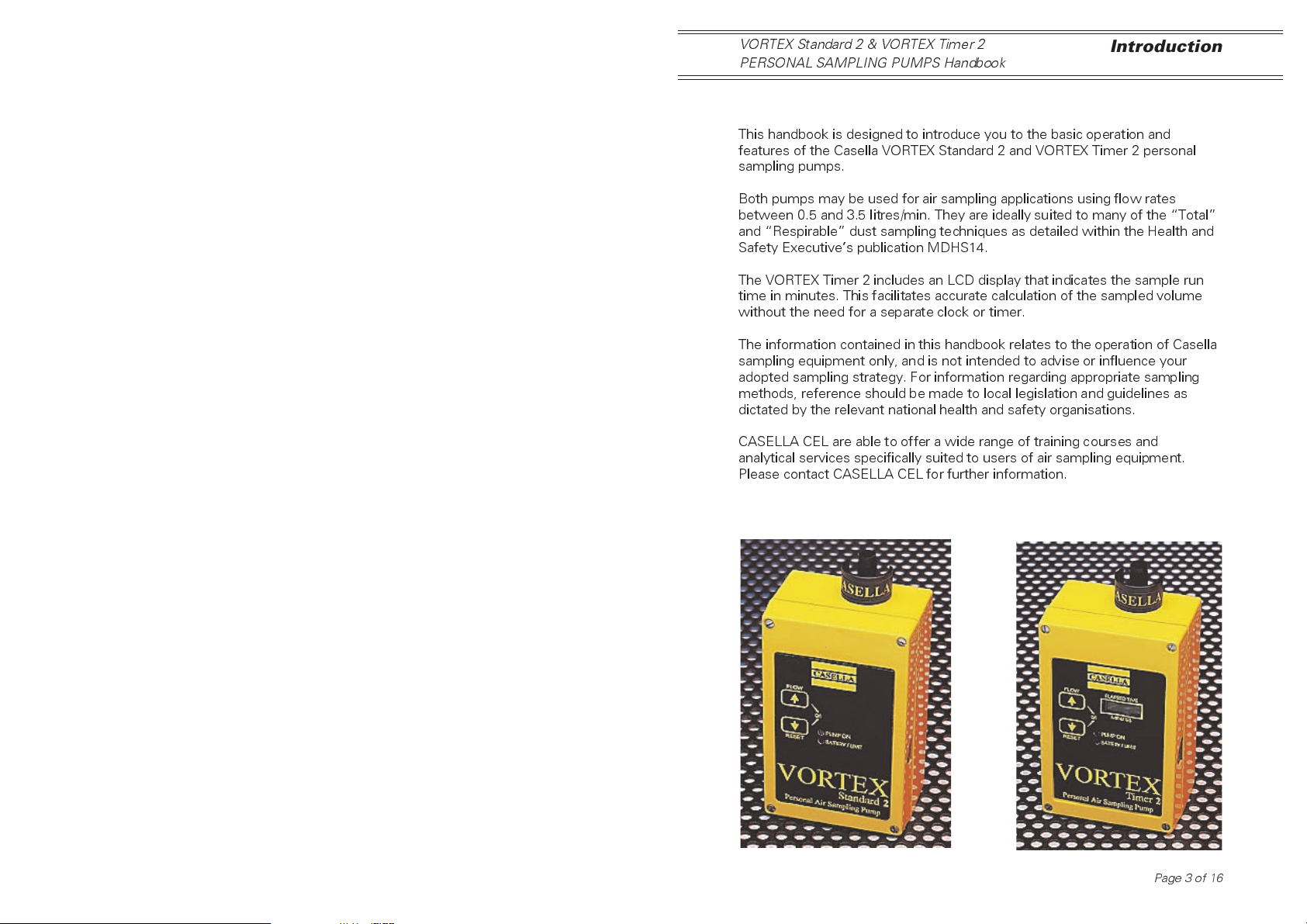
This handbook is designed to introduce you to the basic operation and
features of the Casella VORTEX Standard 2 and VORTEX Timer 2 personal
sampling pumps.
Both pumps may be used for air sampling applications using flow rates
between 0.5 and 3.5 litres/min. They are ideally suited to many of the Total
and Respirable dust sampling techniques as detailed within the Health and
Safety Executives publication MDHS14.
The VORTEX Timer 2 includes an LCD display that indicates the sample run
time in minutes. This facilitates accurate calculation of the sampled volume
without the need for a separate clock or timer.
The information contained in this handbook relates to the operation of Casella
sampling equipment only, and is not intended to advise or influence your
adopted sampling strategy. For information regarding appropriate sampling
methods, reference should be made to local legislation and guidelines as
dictated by the relevant national health and safety organisations.
CASELLA CEL are able to offer a wide range of training courses and
analytical services specifically suited to users of air sampling equipment.
Please contact CASELLA CEL for further information.
Page 3 of 16

Operation
VORTEX Standard 2 & VORTEX Timer 2
PERSONAL SAMPLING PUMPS Handbook
2. OPERATION
These samplers are based upon an efficient diaphragm pump whose flow
rate is precisely maintained by automatic flow control circuitry.
With the exception of the ELAPSED TIME display, the layout of both VORTEX
pumps is identical, as shown below.
Charging
Charging
Socket
Socket
Keys for:
On/Off,
Flow Adjustment,
& Elapsed Time
Reset (Timer 2
On/Off
Flow Adjust
Counter Reset
Keys
only).
Page 4 of 16
Elapsed Time
Indicator
(Timer 2 only)
Indication
Indicator
LEDs
LEDs
VORTEX Standard 2 & VORTEX Timer 2
PERSONAL SAMPLING PUMPS Handbook
Operation
2.1 Battery
A rechargeable nickel-cadmium battery provides, typically in excess, of 8
hours continuous operation. The battery charging socket is located on the
side of the pump. Using the standard charger, the battery will be fully
charged in 14 hours.
To ensure maximum cycle life expectancy of the battery pack, it is recom-
mended that the battery is not left in a fully discharged condition for
extended periods of time. Excessive over charging should also be avoided.
2.2 Battery Low Shut Down
A battery low cut-off facility will turn the pump off once the internal battery
pack becomes fully discharged. This will prevent deep discharge damage
and ensures maximum life of the battery pack. Should the pump be switched
on with a discharged battery, battery-low warning bleeps will be given prior
to the pump shutting itself down.
2.3 Switching the Pump ON and OFF
To switch the pump ON, press the FLOW and RESET keys at the same
time. The buzzer will bleep twice and the green LED will switch on, indicating
PUMP ON.
To switch the pump OFF, press the FLOW and RESET keys at the same
time.
2.4 Indicator LEDs
There are two light emitting diodes (LEDs) located on the front panel of the
instrument.
PUMP ON
Green indicator: used to indicate that the pump is switched ON and is
running. The LED flashes when in flow adjustment mode.
BATTERY LIMIT
Red indicator: used to identify one of two potential error conditions.
Battery Low Warning
When the battery approaches a discharged condition, the red
BATTERY/LIMIT LED flashes slowly and the audible alarm sounds.
Sampling should be terminated and the battery recharged.
Page 5 of 16
 Loading...