

Page 1

CEL-420/460
C
M
p
M
s
M
D
Issue: 4
If you want to get on and use the instruments without any background
information, skip Section 3 and go straight to Section 4.
USERS GUIDE
1. Display
ata is Being Recorded
Battery Condition
Overload has
Occurred
easurement
dentity or Date
urrent Operating
ode, Repeatedly
ressing the
ENU key will
elect each of these in turn
SLM
REC
C-A
DOSE SET UP OPTION
Measurement is Paused
Frequency Weighting
Indicates Active
dB%
960081e
Current Data or Time
Option Keys
Current Units
2. Keys
Display
Switches dosimeter ON/OFF
Changes operating mode)
Accesses stored data
Select active options from the current
menu
DATA
MENU
Starts/Pauses/Restarts a measurement
record
Confirms actions of other keys
Stops a measurement when
followed by
SET
STOP
ENTER
960080
CEL-420/460 Getting Started - Page 53
Page 2
3. Introduction to the Dosimeters
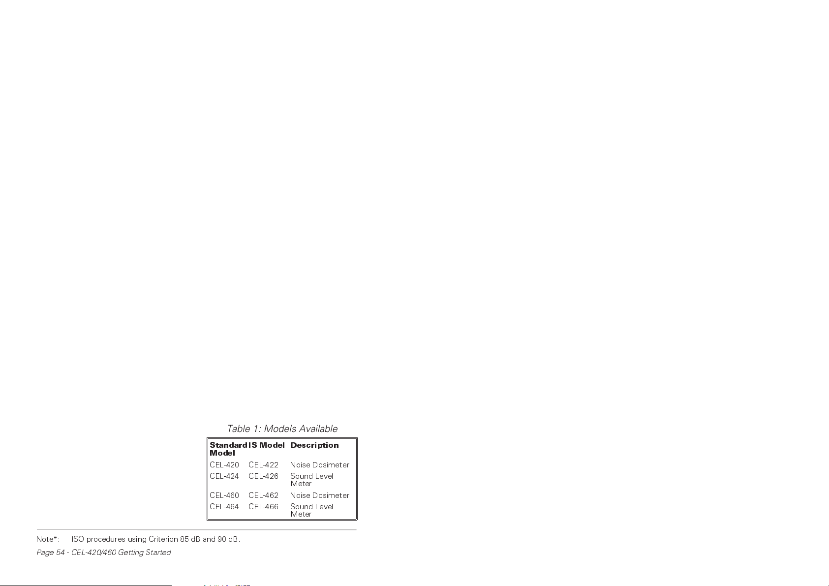
The CEL-420 and CEL-460 Noise Dosimeters measure the frequency
weighted noise exposures and peak sound levels simultaneously. The dosimeter microphone and lead on both models can be replaced by a
sound level meter microphone to offer comprehensive sound level measurement. The dosimeters have the following features.
¤ Four built-in standard dose measurement setups:
OSHA, DOD, ISO85* and ISO90*,
¤ Up to three user specified dose measurement setups,
¤ A single sound level meter setup,
¤ Sixteen dose result stores,
¤ User selection of up to two profiles attached to each
CEL-460 dose measurement,
¤ Self configured storage.
The instruments are built to withstand rough industrial conditions with
cases formed from a polyester/polycarbonate material that gives them a
high resistance to damage. Data integrity is further protected by a dose
microphone lead which is designed to resist knocks and abrasions without affecting the signal passing from microphone to instrument.
Both instruments can be operated and deliver dose and SLM
results without the need for other equipment, beyond an acoustic calibrator. However, they become even more versatile when their measurement and setup data is downloaded to a PC using the CEL-6702 dB10 or
CEL-6704 dB12 Windows™ based software.
These programs have the facilities expected of fully featured Windows™ packages offering post processing, cut and paste between applications and comprehensive word processing capabilities. In addition,
dB12 has extensive on screen graphing facilities.
3.1 Sound Level Meter and Intrinsically Safe Models
Both dosimeters can be converted to a miniature sound level meter by fitting a CEL-425 SLM Microphone
Adaptor. The CEL-420 then becomes
a CEL-424 SLM, while the CEL-460
becomes a CEL-464. For sound level
meter operation refer to Chapter 8.
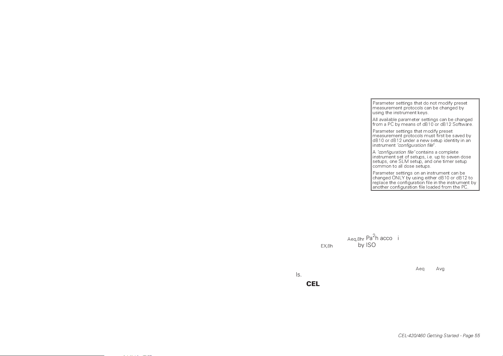
Intrinsically safe versions are
available of both dosimeter and sound
level meter versions, with the full
model line up shown in Table 1.
Table 1: Models Available
Standard
Model
CEL-420 CEL-422 Noise Dosimeter
CEL-424 CEL-426 Sound Level
CEL-460 CEL-462 Noise Dosimeter
CEL-464 CEL-466 Sound Level
IS Model Description
Meter
Meter
Note*: ISO procedures using Criterion 85 dB and 90 dB.
Page 54 - CEL-420/460 Getting Started
Page 3
Intrinsically safe versions are rated to EEx ia IIC T4 for use in
zones 0, 1 and 2 with IS Certificate Number - Ex97E2110X tested to
EN50020 (this corresponds to CENELEC apparatus group IIC, North
American grouping Class1).
3.2 CEL-420 Noise Dosimeter (& CEL-422/424/426)
The following features also apply equally to the CEL-420/422/424/426.
The CEL-420 series instruments are ideal for quick on-site surveys and
for monitoring personal noise exposure in accordance with European ISO
or USA OSHA and DOD standards. For dose measurement,
they are passive instruments
with settings that may be reviewed by key strokes, but
which can be selected only by
means of the dB10 (or dB12)
software. However, all sound
level measurement parameters can be set from the keypad.
There are overlapping
measurement ranges: 50-120
& 70-140 dB, A & C RMS
weightings, Linear & C Peak
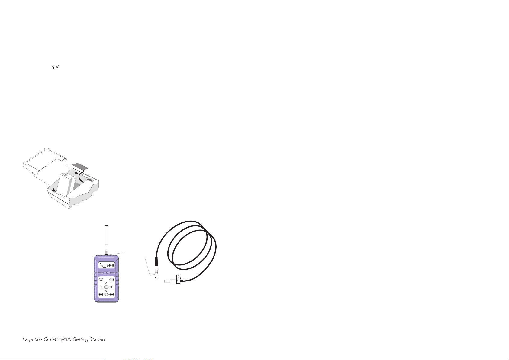
Table 2: Setups and Configuration Files
Parameter settings that do not modify preset
measurement protocols can be changed by
using the instrument keys.
All available parameter settings can be changed
from a PC by means of dB10 or dB12 Software.
Parameter settings that modify preset
measurement protocols must first be saved by
dB10 or dB12 under a new setup identity in an
instrument
A
"configuration file"
instrument set of setups, i.e. up to seven dose
setups, one SLM setup, and one timer setup
common to all dose setups.
Parameter settings on an instrument can be
changed ONLY by using either dB10 or dB12 to
replace the configuration file in the instrument by
another configuration file loaded from the PC.
"configuration file
contains a complete
".
weightings, Fast, Slow &
Impulse time weightings, and energy exchange rates (Q) of 3, 4, 5 & 6.
In dose measurement mode, they display % dose, % dose projected for
an 8 hour period, peak level and measurement duration.
For those countries which are subject to European Union regulations or the equivelent ISO standards, the instruments measure the daily
sound exposure level (L
cal with the L
required by ISO 1999), while for USA OSHA regula-
EX,8h
Aeq,8hr
Pa2h according to IEC 1252, that is identi-
tions they measure the Time Weighted Average Level (TWA).
When used as a sound level meter they display sound level,
maximum sound level, peak and time-averaged (L
Aeq
or L
Avg
) sound
levels.
3.3 CEL-460 Logging Noise Dosimeter
(& CEL-462/464/466)
The following features also apply equally to the CEL-460/462/464/466.
The CEL-460 series instruments are recommended for detailed measurements as they feature extended processing and memory functions.
There is an additional 30-100 dB measurement range that can be used
for environmental surveys, and automatic run timing facilities controlled
CEL-420/460 Getting Started - Page 55
Page 4
by the built-in clock. There are time-history recording capabilities that allow up to two profiles to be saved with each dose result set in a separate profile store. Sampling times can be specified between 1 s and 1
hour, while profile storage is in excess of 50 000 data points.
The instruments are able to measure and save up to five user
specified L
values (exceedance level percentiles). Run durations speci-
n
fied via instrument keys, by dB10 or dB12, and start and stop times preset via dB10 or dB12 can be switched on or off from the instrument
keys. Other settings can be changed only by dB10 and dB12 Software.
When data saved by a CEL-460 instrument is downloaded to a
PC, the user can specify a period over which to re-calculate projected %
dose values. The software can also calculate six exceedance time percentiles with levels preset to values specified by measurement standards,
plus one user specified time percentile.
4. Install Battery & Microphone
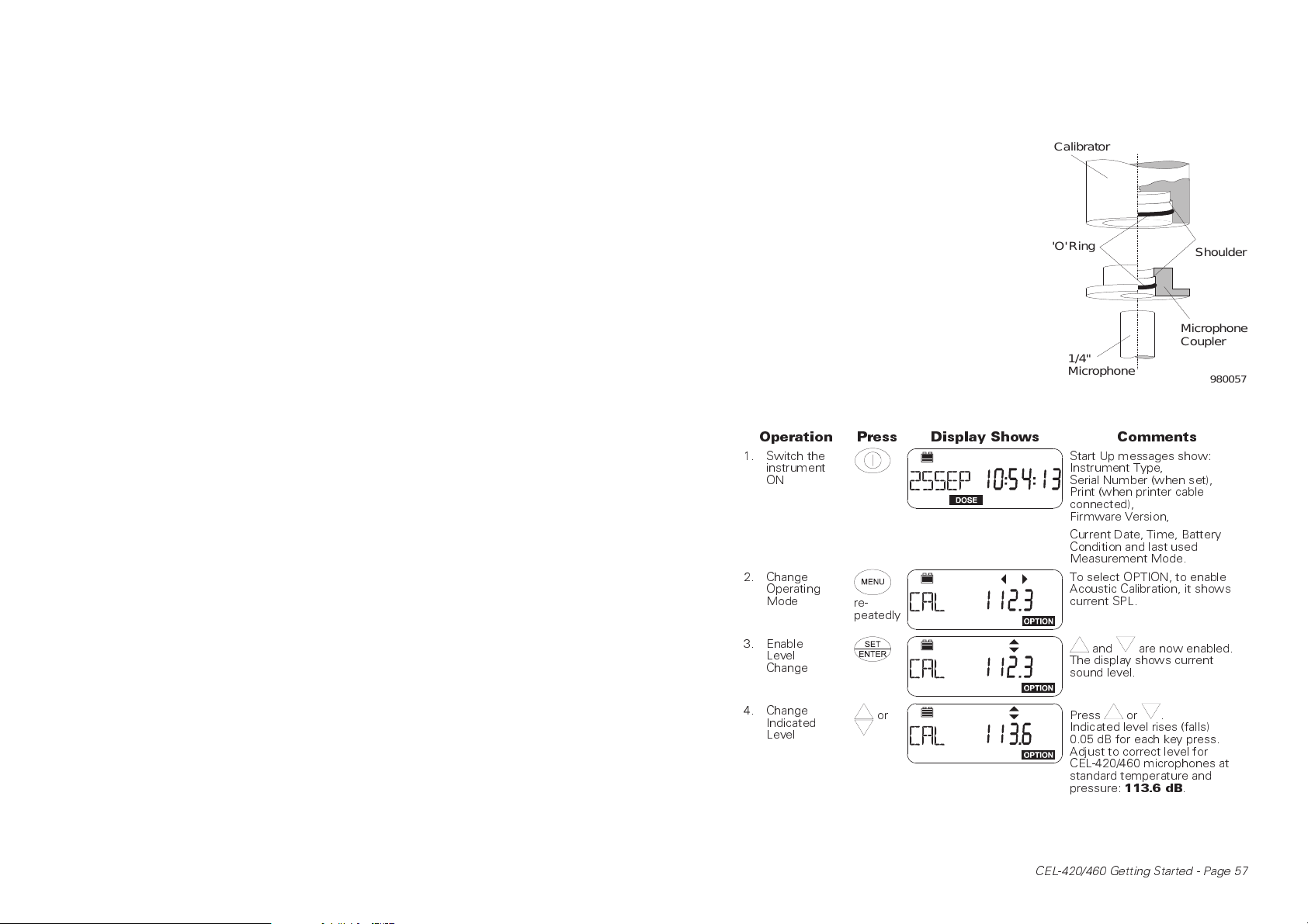
Connect a new 6LF22 or equivalent 9 V battery to the terminals in the battery
compartment in the rear of the instrument.
With the instrument switched OFF,
insert the lead connector of the CEL-6681
Dosimeter Microphone (or the connector
on the CEL-425 SLM Adaptor stalk) into
960079
the socket on the top end of the case with
the red dot facing the front of the
dosimeter.
CEL-425
SLM Adaptor
Remove the
connector ONLY by pull-
Red "Dot"
ing on the knurled
sleeve.
DATA
MENU
SET
STOP
ENTER
CEL-6681
Dosimeter Microphone
990022
For IS versions, use ONLY Duracel® MN1604
batteries. Install and remove the battery and microphone
ONLY in a non-hazardous area.
Page 56 - CEL-420/460 Getting Started
Page 5
5. Perform Acoustic Calibration
'
Operations are performed by a sequence of key strokes.
Perform a field accuracy check
each time the instrument is switched ON
using a CEL-282 (Class 2) or CEL-284/2
(Class 1) Calibrator as follows.
Fit the microphone into the CEL4725 Coupler supplied with the calibrator,
making sure it is pushed firmly into contact
with the shoulder in the coupler cavity.
Then fit the coupler complete with microphone into a CEL-282 (or CEL-284/2) Calibrator, again ensuring that it makes contact
with the shoulder in the calibrator cavity.
(To aid removal, the coupler flange does
not fit close against the calibrator housing).
Switch the calibrator ON, then follow the instruction after the Start Up sequence of displays has finished.
Operation Press Display Shows Comments
1. Switch the
instrument
ON
2. Change
Operating
Mode
re-
peatedly
Calibrator
O'Ring
Microphone
Coupler
1/4"
Microphone
Start Up messages show:
Instrument Type,
Serial Number (when set),
Print (when printer cable
connected),
Firmware Version,
Current Date, Time, Battery
Condition and last used
Measurement Mode.
To select OPTION, to enable
Acoustic Calibration, it shows
current SPL.
Shoulder
980057
3. Enable
Level
Change
4. Change
Indicated
Level
or
CEL-420/460 Getting Started - Page 57
and are now enabled.
The display shows current
sound level.
Press or .
Indicated level rises (falls)
0.05 dB for each key press.
Adjust to correct level for
CEL-420/460 microphones at
standard temperature and
pressure:
113.6 dB
.
Page 6
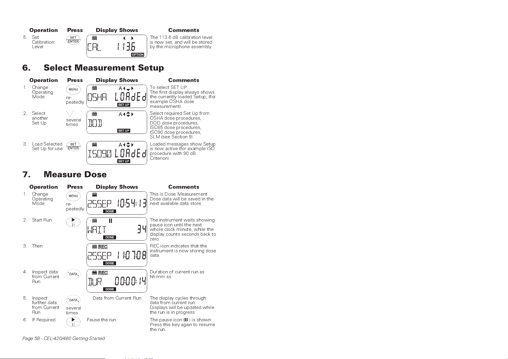
Operation Press Display Shows Comments
5. Set
Calibration
Level
The 113.6 dB calibration level
is now set, and will be stored
by the microphone assembly.
6. Select Measurement Setup
Operation Press Display Shows Comments
1. Change
Operating
Mode
2. Select
another
Set Up
3. Load Selected
Set Up for use
re-
peatedly
several
times
To select SET UP.
The first display always shows
the currently loaded Setup, (for
example OSHA dose
measurement).
Select required Set Up from
OSHA dose procedures,
DOD dose procedures,
ISO85 dose procedures,
ISO90 dose procedures,
SLM (see Section 9).
Loaded messages show Setup
is now active (for example ISO
procedure with 90 dB
Criterion).
7. Measure Dose
Operation Press Display Shows Comments
1. Change
Operating
Mode
re-
peatedly
This is Dose Measurement.
Dose data will be saved in the
next available data store.
2. Start Run The instrument waits showing
3. Then REC icon indicates that the
4. Inspect data
from Current
Run
5. Inspect
further data
from Current
Run
6. If Required Pause the run.
Page 58 - CEL-420/460 Getting Started
several
times
Data from Current Run The display cycles through
pause icon until the next
whole clock minute, while the
display counts seconds back to
zero.
instrument is now storing dose
data.
Duration of current run as
hh:mm:ss.
data from current run.
Displays will be updated while
the run is in progress.
The pause icon (II) is shown.
Press this key again to resume
the run.
Page 7
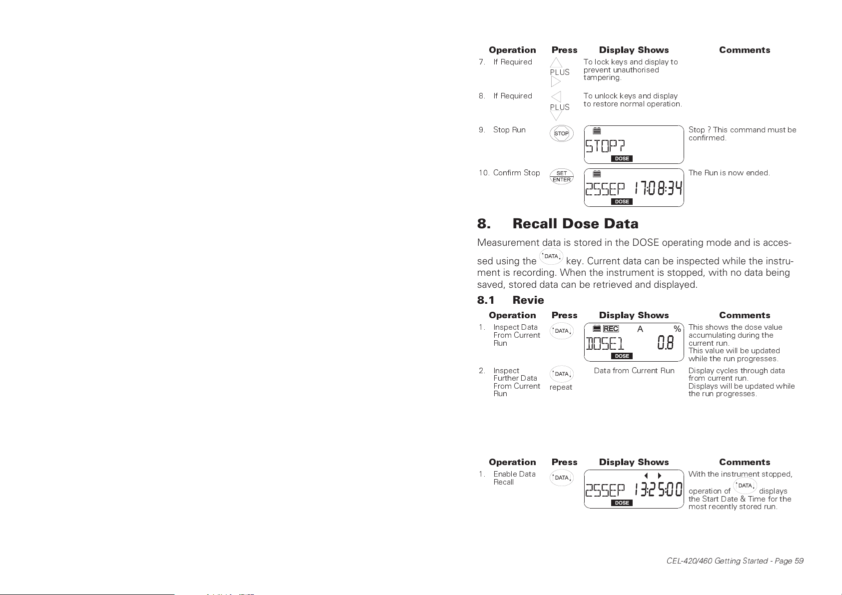
Operation Press Display Shows Comments
7. If Required
PLUS
To lock keys and display to
prevent unauthorised
tampering.
8. If Required
PLUS
9. Stop Run Stop ? This command must be
10. Confirm Stop The Run is now ended.
To unlock keys and display
to restore normal operation.
confirmed.
8. Recall Dose Data
Measurement data is stored in the DOSE operating mode and is acces-
sed using the key. Current data can be inspected while the instrument is recording. When the instrument is stopped, with no data being
saved, stored data can be retrieved and displayed.
8.1 Review Data From Current Run
Operation Press Display Shows Comments
1. Inspect Data
From Current
Run
2. Inspect
Further Data
From Current
Run
repeat
Data from Current Run Display cycles through data
8.2 Review Stored Data
Stored data is identified by date and measurement start time and up to
16 runs can be stored simultaneously before the memory is overwritten
by a "first-in/first-out" process.
Operation Press Display Shows Comments
1. Enable Data
Recall
This shows the dose value
accumulating during the
current run.
This value will be updated
while the run progresses.
from current run.
Displays will be updated while
the run progresses.
With the instrument stopped,
operation of displays
the Start Date & Time for the
most recently stored run.
CEL-420/460 Getting Started - Page 59
Page 8
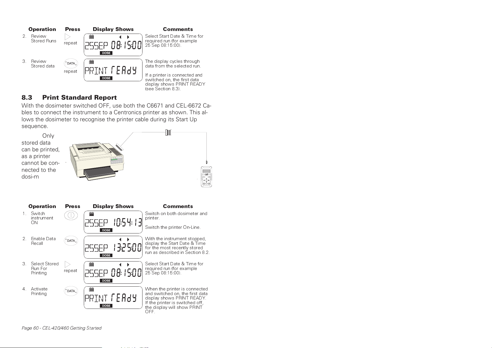
Operation Press Display Shows Comments
2. Review
Stored Runs
repeat
Select Start Date & Time for
required run (for example
25 Sep 08:15:00).
3. Review
Stored data
repeat
The display cycles through
data from the selected run.
If a printer is connected and
switched on, the first data
display shows PRINT READY
(see Section 8.3).
8.3 Print Standard Report
With the dosimeter switched OFF, use both the C6671 and CEL-6672 Cables to connect the instrument to a Centronics printer as shown. This allows the dosimeter to recognise the printer cable during its Start Up
sequence.
Only
stored data
can be printed,
as a printer
cannot be connected to the
dosi-meter at
the same time
960087
as the microphone.
Operation Press Display Shows Comments
1. Switch
instrument
ON
C6672 Active
Printer Cable
Centronics Printer
Switch on both dosimeter and
printer.
Switch the printer On-Line.
Communications
C6671
Cable
CEL-420/
CEL-460
Series
2. Enable Data
Recall
3. Select Stored
Run For
Printing
4. Activate
Printing
Page 60 - CEL-420/460 Getting Started
repeat
With the instrument stopped,
display the Start Date & Time
for the most recently stored
run as described in Section 8.2.
Select Start Date & Time for
required run (for example
25 Sep 08:15:00).
When the printer is connected
and switched on, the first data
display shows PRINT READY.
If the printer is switched off,
the display will show PRINT
OFF.
Page 9
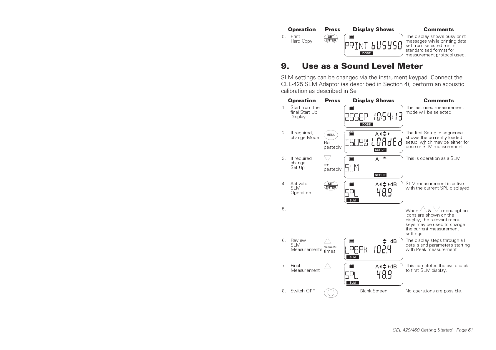
Operation Press Display Shows Comments
5. Print
Hard Copy
The display shows busy print
messages while printing data
set from selected run in
standardised format for
measurement protocol used.
9. Use as a Sound Level Meter
SLM settings can be changed via the instrument keypad. Connect the
CEL-425 SLM Adaptor (as described in Section 4), perform an acoustic
calibration as described in Section 5, then proceed as follows.
Operation Press Display Shows Comments
1. Start from the
final Start Up
Display
The last used measurement
mode will be selected.
2. If required,
change Mode
3. If required
change
Set Up
4. Activate
SLM
Operation
5.
6. Review
SLM
Measurements
7. Final
Measurement
8. Switch OFF Blank Screen No operations are possible.
Re-
peatedly
re-
peatedly
several
times
The first Setup in sequence
shows the currently loaded
setup, which may be either for
dose or SLM measurement.
This is operation as a SLM.
SLM measurement is active
with the current SPL displayed.
When & menu option
icons are shown on the
display, the relevant menu
keys may be used to change
the current measurement
settings.
The display steps through all
details and parameters starting
with Peak measurement.
This completes the cycle back
to first SLM display.
CEL-420/460 Getting Started - Page 61
Page 10
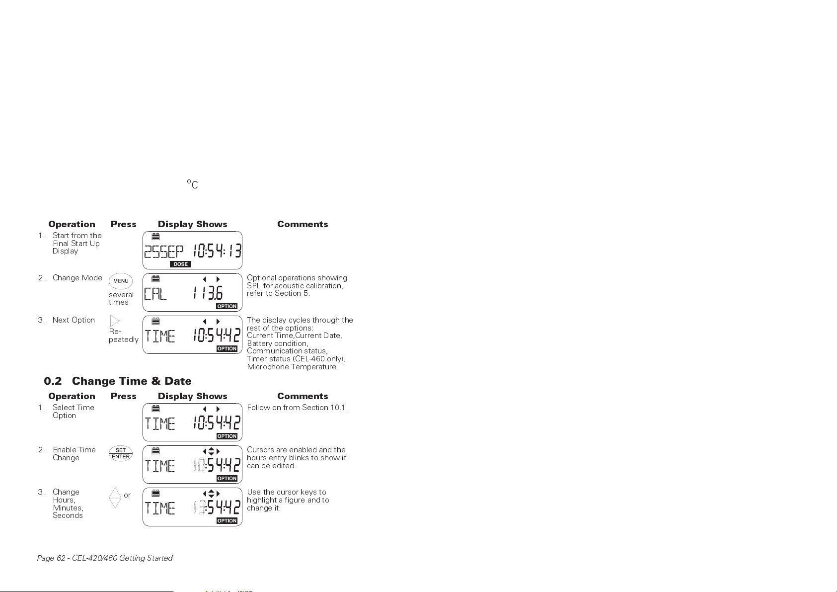
10. Selecting & Changing Options
The OPTION operating mode contains the part of the program which
allows the following items to be checked or adjusted.
Acoustic calibration (see Section 5),
Adjustment of the calendar clock and time,
Battery voltage,
Communication status when the dosimeter is connected to a
PC for use with dB10 or dB12 Soundtrack Software,
Activating the run timer commands set by dB10 and dB12
(only on a CEL-460),
Microphone temperature (
10.1 Review Options
Operation Press Display Shows Comments
1. Start from the
Final Start Up
Display
o
C).
2. Change Mode
3. Next Option
several
times
Re-
peatedly
Optional operations showing
SPL for acoustic calibration,
refer to Section 5.
The display cycles through the
rest of the options:
Current Time,Current Date,
Battery condition,
Communication status,
Timer status (CEL-460 only),
Microphone Temperature.
10.2 Change Time & Date
Operation Press Display Shows Comments
1. Select Time
Option
2. Enable Time
Change
3. Change
Hours,
Minutes,
Seconds
Page 62 - CEL-420/460 Getting Started
or
Follow on from Section 10.1.
Cursors are enabled and the
hours entry blinks to show it
can be edited.
Use the cursor keys to
highlight a figure and to
change it.
Page 11
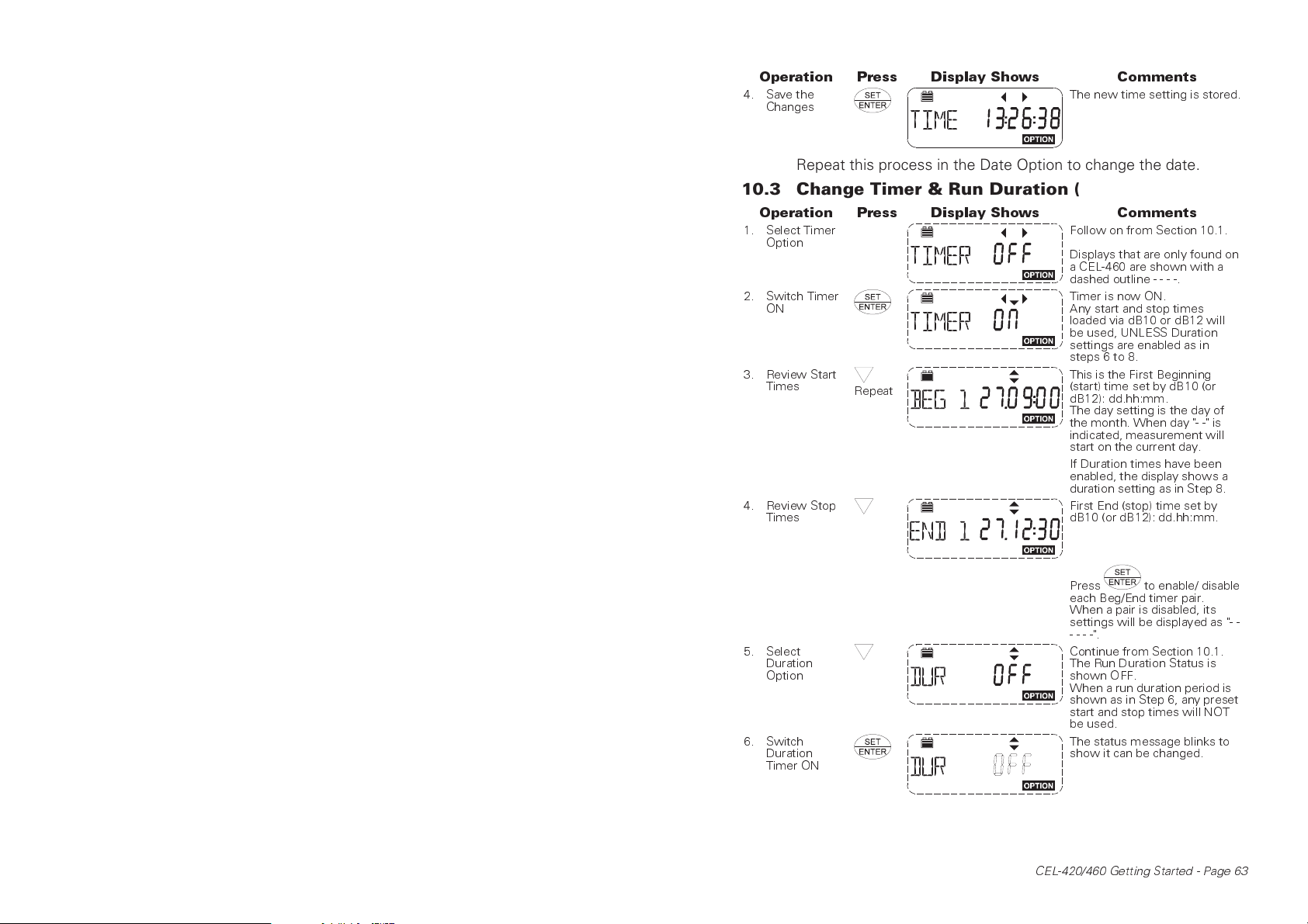
Operation Press Display Shows Comments
4. Save the
Changes
The new time setting is stored.
Repeat this process in the Date Option to change the date.
10.3 Change Timer & Run Duration (CEL-460 only)
Operation Press Display Shows Comments
1. Select Timer
Option
2. Switch Timer
ON
3. Review Start
Times
4. Review Stop
Times
Repeat
Follow on from Section 10.1.
Displays that are only found on
a CEL-460 are shown with a
dashed outline----.
Timer is now ON.
Any start and stop times
loaded via dB10 or dB12 will
be used, UNLESS Duration
settings are enabled as in
steps 6 to 8.
This is the First Beginning
(start) time set by dB10 (or
dB12): dd.hh:mm.
The day setting is the day of
the month. When day "- -" is
indicated, measurement will
start on the current day.
If Duration times have been
enabled, the display shows a
duration setting as in Step 8.
First End (stop) time set by
dB10 (or dB12): dd.hh:mm.
5. Select
Duration
Option
6. Switch
Duration
Timer ON
Press to enable/ disable
each Beg/End timer pair.
When a pair is disabled, its
settings will be displayed as "- -
----".
Continue from Section 10.1.
The Run Duration Status is
shown OFF.
When a run duration period is
shown as in Step 6, any preset
start and stop times will NOT
be used.
The status message blinks to
show it can be changed.
CEL-420/460 Getting Started - Page 63
Page 12
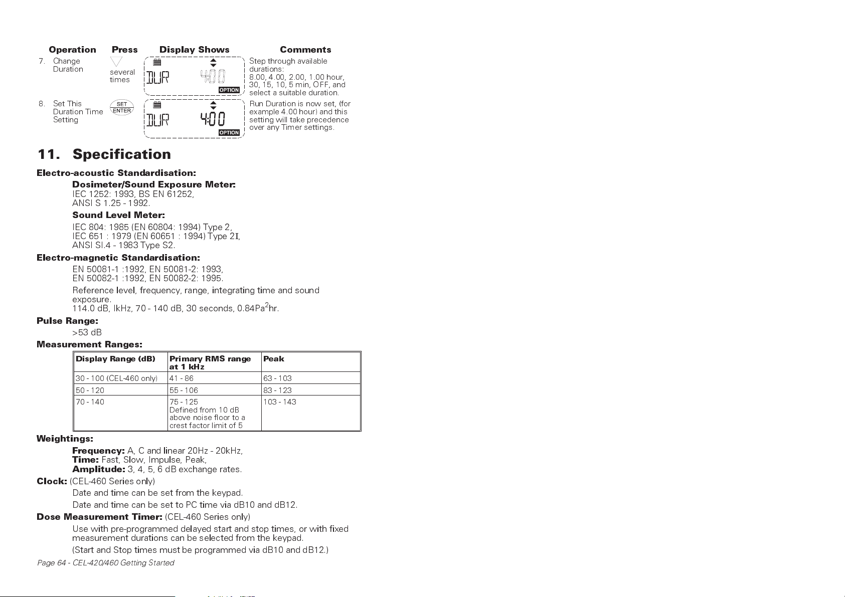
Operation Press Display Shows Comments
7. Change
Duration
8. Set This
Duration Time
Setting
several
times
Step through available
durations:
8.00, 4.00, 2.00, 1.00 hour,
30, 15, 10, 5 min, OFF, and
select a suitable duration.
Run Duration is now set, (for
example 4.00 hour) and this
setting will take precedence
over any Timer settings.
11. Specification
Electro-acoustic Standardisation:
Dosimeter/Sound Exposure Meter:
IEC 1252: 1993, BS EN 61252,
ANSI S 1.25 - 1992.
Sound Level Meter:
IEC 804: 1985 (EN 60804: 1994) Type 2,
IEC 651 : 1979 (EN 60651 : 1994) Type 2
ANSI SI.4 - 1983 Type S2.
Electro-magnetic Standardisation:
EN 50081-1 :1992, EN 50081-2: 1993,
EN 50082-1 :1992, EN 50082-2: 1995.
Reference level, frequency, range, integrating time and sound
exposure.
114.0 dB, IkHz, 70 - 140 dB, 30 seconds, 0.84Pa2hr.
Pulse Range:
>53 dB
Measurement Ranges:
Display Range (dB) Primary RMS range
30 - 100 (CEL-460 only) 41 - 86 63 - 103
50 - 120 55 - 106 83 - 123
70 - 140 75 - 125
at 1 kHz
Defined from 10 dB
above noise floor to a
crest factor limit of 5
Weightings:
Clock:
Frequency:
Time:
Amplitude:
(CEL-460 Series only)
A, C and linear 20Hz - 20kHz,
Fast, Slow, Impulse, Peak,
3, 4, 5, 6 dB exchange rates.
Date and time can be set from the keypad.
Date and time can be set to PC time via dB10 and dB12.
Dose Measurement Timer:
(CEL-460 Series only)
Use with pre-programmed delayed start and stop times, or with fixed
measurement durations can be selected from the keypad.
(Start and Stop times must be programmed via dB10 and dB12.)
Page 64 - CEL-420/460 Getting Started
I
,
Peak
103 - 143
Page 13
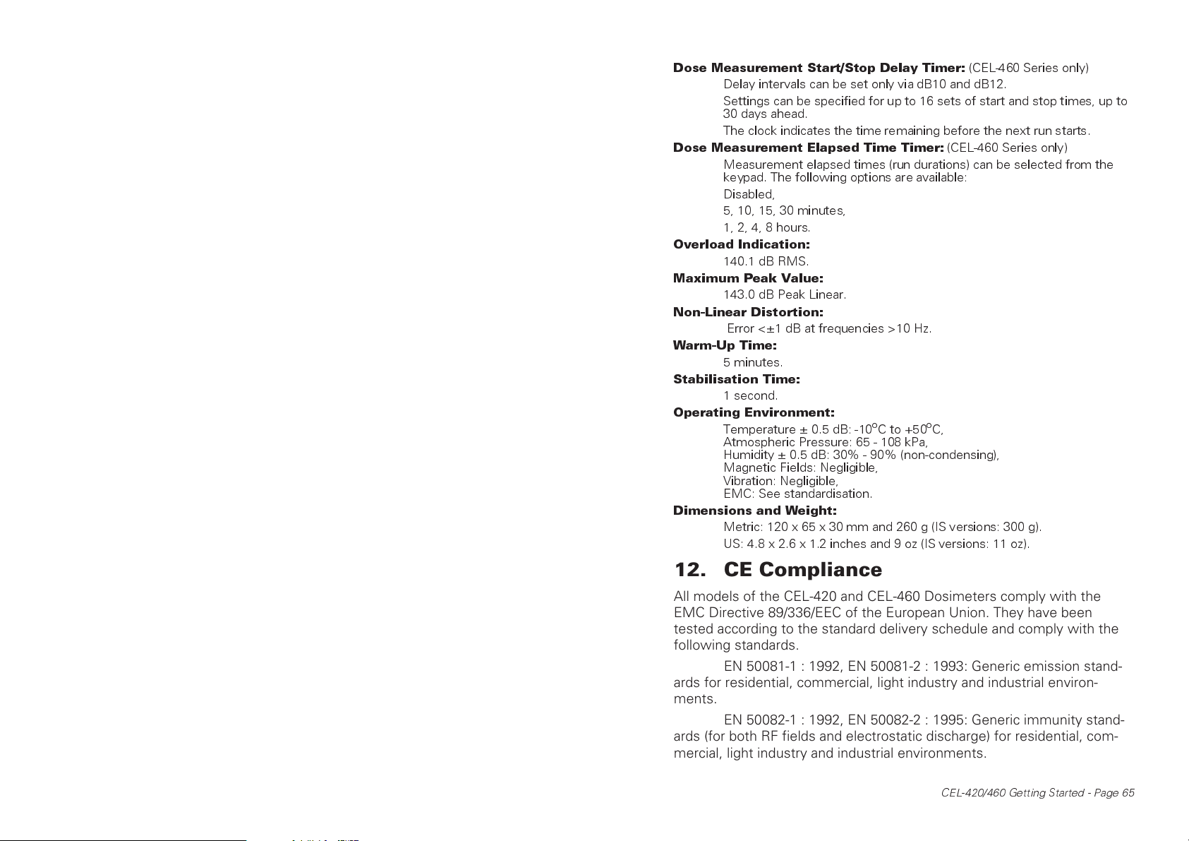
Dose Measurement Start/Stop Delay Timer:
Delay intervals can be set only via dB10 and dB12.
Settings can be specified for up to 16 sets of start and stop times, up to
30 days ahead.
The clock indicates the time remaining before the next run starts.
Dose Measurement Elapsed Time Timer:
Measurement elapsed times (run durations) can be selected from the
keypad. The following options are available:
Disabled,
5, 10, 15, 30 minutes,
1, 2, 4, 8 hours.
Overload Indication:
140.1 dB RMS.
Maximum Peak Value:
143.0 dB Peak Linear.
Non-Linear Distortion:
Error <±1 dB at frequencies >10 Hz.
Warm-Up Time:
5 minutes.
Stabilisation Time:
1 second.
Operating Environment:
Temperature ± 0.5 dB: -10oC to +50oC,
Atmospheric Pressure: 65 - 108 kPa,
Humidity ± 0.5 dB: 30% - 90% (non-condensing),
Magnetic Fields: Negligible,
Vibration: Negligible,
EMC: See standardisation.
Dimensions and Weight:
Metric: 120 x 65 x 30 mm and 260 g (IS versions: 300 g).
US: 4.8 x 2.6 x 1.2 inches and 9 oz (IS versions: 11 oz).
(CEL-460 Series only)
(CEL-460 Series only)
12. CE Compliance
All models of the CEL-420 and CEL-460 Dosimeters comply with the
EMC Directive 89/336/EEC of the European Union. They have been
tested according to the standard delivery schedule and comply with the
following standards.
EN 50081-1 : 1992, EN 50081-2 : 1993: Generic emission standards for residential, commercial, light industry and industrial environments.
EN 50082-1 : 1992, EN 50082-2 : 1995: Generic immunity standards (for both RF fields and electrostatic discharge) for residential, commercial, light industry and industrial environments.
CEL-420/460 Getting Started - Page 65
Page 14
13. Intrinsically Safe Models
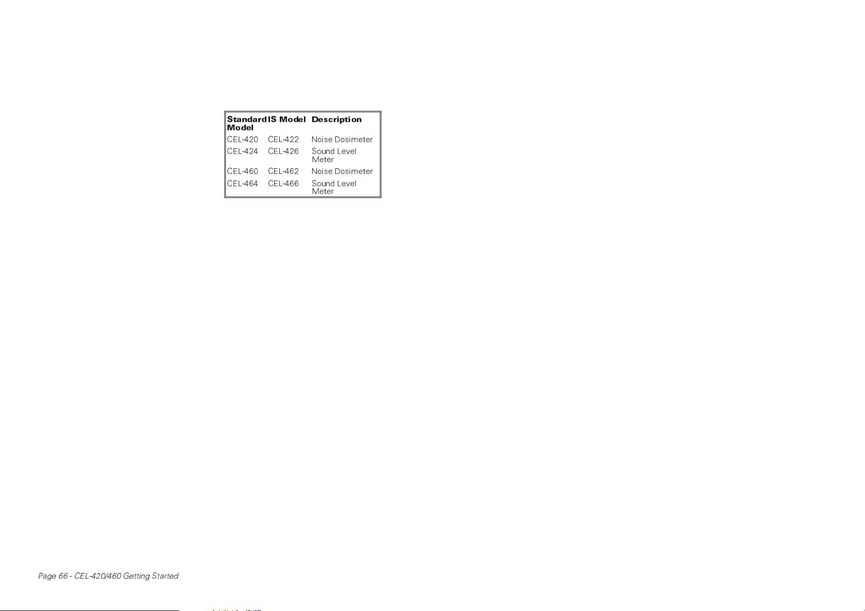
Four models in the CEL-420/460 series are available with Intrinsic Safety
approval for use in hazardous areas. Their instrument numbers are
shown in the table.
The operation of each model
is identical to its non-IS counterpart.
The Noise Dosimeter versions use
the standard CEL-6681 microphone
on a 0.75 m cable for personal use
whereas the sound level meter versions use the standard CEL-425 microphone adaptor.
The Intrinsically Safe versions are fitted with a different firmware version but are functionally identical to the standard products. They may be connected to a personal computer for setup and download of results using the CEL-6702 or 6704
Windows software packages.
Products rating - to EEx ia IIC T4 for use in zones 0, 1 and 2. Intrinsically Safe Certificate Number - Ex97E2110X tested to EN50020 (this
corresponds to CENELEC apparatus group IIC, North American grouping
Class1).
Approved Power Supply
Only the Duracel® MN1604 alkaline type battery may be used in these
meters (9 V radio battery). The use of any other battery will invalidate the
intrinsically safe certification.
Battery Life
Approximately 30 hours under typical conditions.
Special instructions
The battery must be replaced only in a non-hazardous area.
The instruments must be calibrated in a non-hazardous area following the same instructions as for the standard models.
Any repairs needed for the Intrinsically Safe models must be carried out only by an approved CASELLA CEL service centre following approved written procedures.
Standard
Model
CEL-420 CEL-422 Noise Dosimeter
CEL-424 CEL-426 Sound Level
CEL-460 CEL-462 Noise Dosimeter
CEL-464 CEL-466 Sound Level
IS Model Description
Meter
Meter
Page 66 - CEL-420/460 Getting Started
Page 15

14. Instrument Servicing & Warranty
Arrangements
To ensure its conformity with the specification, this instrument is
thoroughly inspected and it's accuracy verified prior to dispatch. All technical information is filed under the instrument serial number, which
should, therefore, be quoted in any correspondence.
The manufacturers undertake to rectify any defect in the instru-
ment that is directly attributable to faulty design or assembly, and which
becomes apparent during the warranty period. In order to take advantage
of this warranty, the instrument must be returned, carriage paid, to the
manufacturer's factory or accredited agent, where necessary repairs will
be carried out.
The warranty period runs for 12 months from the date of receipt
of goods, with exceptions on certain specialised components supplied by
other manufacturers which may be warranted for shorter or longer periods by their actual manufacturers. In all such cases, the benefit of these
undertakings will be passed on to the user.
CASELLA CEL's liability is limited to items of their own manufac-
ture, and they do not accept liability for any loss resulting from the operation or interpretation of the results from this equipment.
To obtain repair under warranty, the instrument should be
packed and returned in it's original packing or an equivalent either to
CASELLA CEL's local agent, or in the case of domestic sales, to the
CASELLA CEL Service Department at Bedford. Please include the following information:
Instrument Type(s), Serial Number(s) and Firmware Version
Number(s),
Customer name and address,
Contact name and phone number,
Details of any PC and Software involved, including Version
Number(s),
Reason for returning the equipment with a detailed description
of the fault,
List of any error messages that may have been displayed.
The necessary adjustments or repairs will be carried out, and the instrument returned as soon as possible.
A comprehensive Instrument Calibration Maintenance Agree-
ment (ICMA) scheme is available to extend the initial warranty period of
this instrument. At the end of the first warranty period, it is recom-
CEL-420/460 Getting Started - Page 67
Page 16

mended that the equipment be returned to the Service and Verification
Department at Bedford, where it will be inspected and entered into the
ICMA scheme as required. The warranty will then be extended for the period stated on the individual schedule. Please contact your local
CASELLA CEL agent for full details of this service.
After the warranty has expired (except on approved accounts)
service work is undertaken against quotations, and all packing and transit
costs are charged extra.
Page 68 - CEL-420/460 Getting Started
 Loading...