

Page 1
MULTIMET Wind Speed and Direction System
& OnlinePro Software - Users Handbook
December 2002
MULTIMET
Wind Speed and
Direction System
Users Handbook
HB3272-03
(For use with Online Pro
Application Software)
COPYRIGHT
The copyright in this document which contains proprietary information is vested
in CASELLA CEL LIMITED. The contents of this document must not be used for
purposes other than for which it has been supplied or reproduced or disclosed
wholly or in part without the prior written permission of
CASELLA CEL LIMITED
CASELLA CEL
Regent House
Wolseley Road
Kempston
Bedford
MK42 7JY, U.K.
Phone: +44 (0)1234 844100
Fax: +44 (0)1234 841490
E-Mail: [email protected]
Web: www.casellacel.com
CASELLA USA
17 Old Nashua Road #15
Amherst
NH 03031,
U.S.A.
Toll Free: +1 800 366 2966
Fax: +1 603 672 8053
E-mail: [email protected]
Web: www.casellausa.com
Page 2
MULTIMET Wind Speed and Direction System
& OnlinePro Software - Users Handbook
Page 2 of 16
Page 3
MULTIMET Wind Speed and Direction System
& OnlinePro Software - Users Handbook
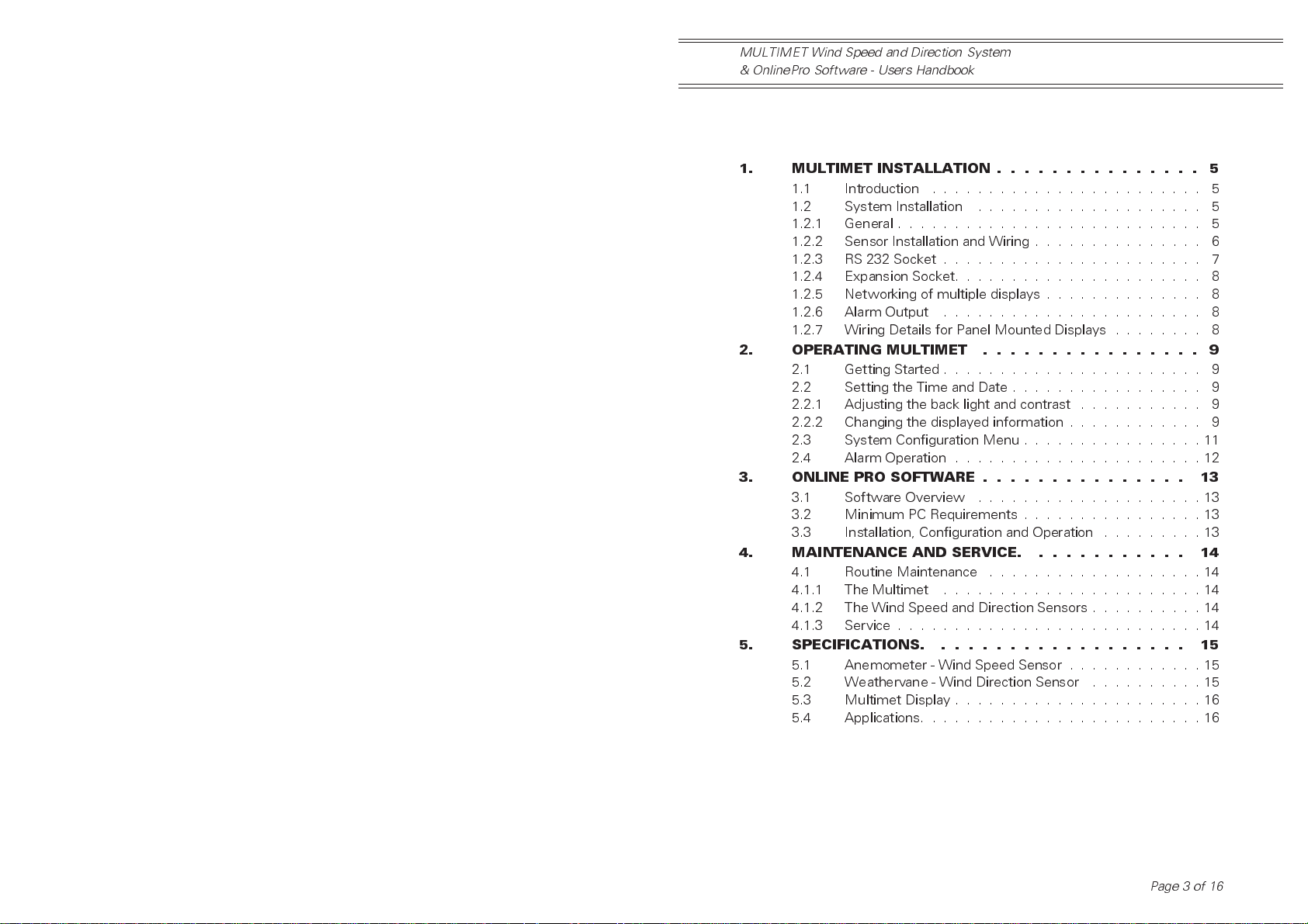
Table of Contents
Chapter ..................Page
1. MULTIMET INSTALLATION ............... 5
1.1 Introduction . . . . . . . . . . . . . . . . . . . . . . . . 5
1.2 System Installation . . . . . . . . . . . . . . . . . . . . 5
1.2.1 General . . . . . . . . . . . . . . . . . . . . . . . . . . . 5
1.2.2 Sensor Installation and Wiring . . . . . . . . . . . . . . . 6
1.2.3 RS 232 Socket . . . . . . . . . . . . . . . . . . . . . . . 7
1.2.4 Expansion Socket. . . . . . . . . . . . . . . . . . . . . . 8
1.2.5 Networking of multiple displays . . . . . . . . . . . . . . 8
1.2.6 Alarm Output . . . . . . . . . . . . . . . . . . . . . . . 8
1.2.7 Wiring Details for Panel Mounted Displays . . . . . . . . 8
2. OPERATING MULTIMET ................ 9
2.1 Getting Started . . . . . . . . . . . . . . . . . . . . . . . 9
2.2 Setting the Time and Date . . . . . . . . . . . . . . . . . 9
2.2.1 Adjusting the back light and contrast . . . . . . . . . . . 9
2.2.2 Changing the displayed information . . . . . . . . . . . . 9
2.3 System Configuration Menu . . . . . . . . . . . . . . . . 11
2.4 Alarm Operation . . . . . . . . . . . . . . . . . . . . . . 12
3. ONLINE PRO SOFTWARE ............... 13
3.1 Software Overview . . . . . . . . . . . . . . . . . . . . 13
3.2 Minimum PC Requirements . . . . . . . . . . . . . . . . 13
3.3 Installation, Configuration and Operation . . . . . . . . . 13
4. MAINTENANCE AND SERVICE. ........... 14
4.1 Routine Maintenance . . . . . . . . . . . . . . . . . . . 14
4.1.1 The Multimet . . . . . . . . . . . . . . . . . . . . . . . 14
4.1.2 The Wind Speed and Direction Sensors . . . . . . . . . . 14
4.1.3 Service . . . . . . . . . . . . . . . . . . . . . . . . . . . 14
5. SPECIFICATIONS. .................. 15
5.1 Anemometer - Wind Speed Sensor . . . . . . . . . . . . 15
5.2 Weathervane - Wind Direction Sensor . . . . . . . . . . 15
5.3 Multimet Display . . . . . . . . . . . . . . . . . . . . . . 16
5.4 Applications. . . . . . . . . . . . . . . . . . . . . . . . . 16
Page 3 of 16
Page 4
Contents
MULTIMET Wind Speed and Direction System
& OnlinePro Software - Users Handbook
Page 4 of 16
Page 5
MULTIMET Wind Speed and Direction System
& OnlinePro Software - Users Handbook
1. MULTIMET INSTALLATION
1.1 Introduction
The Multimet is designed as a
professional, reliable and easy to use
system satisfying the demands of
industrial, meteorological, aviation and
marine users. The system can display and
record wind speed and direction data in a
variety of clear and unambiguous formats
ideally suited to many different applications.
A high contrast, transflective LCD
display with back light facility maintains
crystal clarity in all lighting conditions.
Multimet display units may be networked
together to provide distributed multi-user
access to real time wind data.
A comprehensive PC software
package, Online Pro, supports the
system and provides graphical
presentation of real time and historical
wind data. The software operates in the
WindowsTMenvironment and may be user
configured to suit specific monitoring
requirements.
1.2 System Installation
1.2.1 General
The Casella CEL Multimet is available in
either a desktop enclosure or panel mount
format:
Desk Top Systems
The desk top version should be positioned
in the desired location ensuring
adequate clearance behind the unit for
interconnecting cables.
Simple connection of cables for
sensors, data communications and
power supply is achieved using
connectors located on the rear of the
instrument.
Panel Mounted Installation
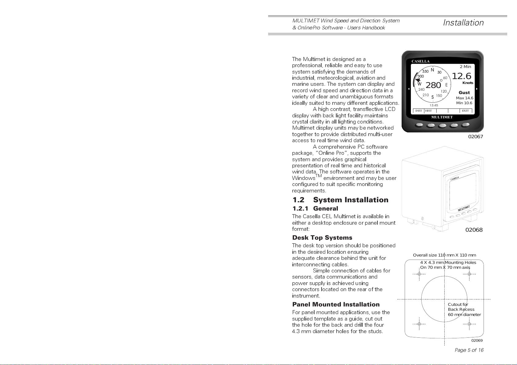
For panel mounted applications, use the
supplied template as a guide, cut out
the hole for the back and drill the four
4.3 mm diameter holes for the studs.
Installation
N
N
330
330
30
300
300
W
W
240
INST HIST EXIT
Overall size 110 mm X 110 mm
30
°
280
120
210
150
S
S
13:45
4 X 4.3 mm Mounting Holes
On 70 mm X 70 mm axis
2 Min
60
12.6
Knots
E
Gust
Max 14.6
Min 10.6
02068
Cutout for
Back Recess
60 mm diameter
Page 5 of 16
02067
02069
Page 6
Installation
MULTIMET Wind Speed and Direction System
& OnlinePro Software - Users Handbook
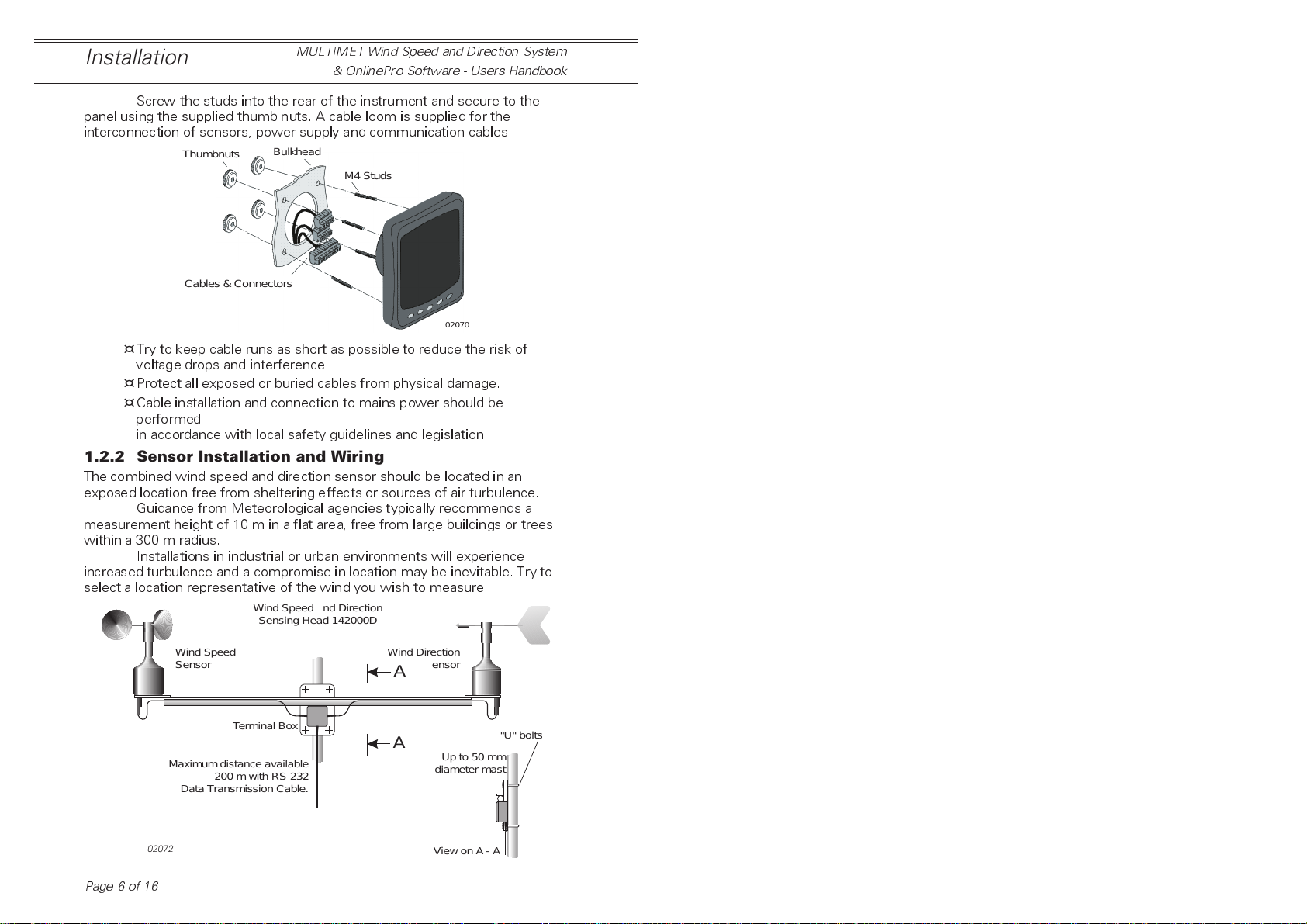
Screw the studs into the rear of the instrument and secure to the
panel using the supplied thumb nuts. A cable loom is supplied for the
interconnection of sensors, power supply and communication cables.
Thumbnuts
Cables & Connectors
¤
Try to keep cable runs as short as possible to reduce the risk of
Bulkhead
M4 Studs
02070
voltage drops and interference.
¤
Protect all exposed or buried cables from physical damage.
¤
Cable installation and connection to mains power should be
performed
in accordance with local safety guidelines and legislation.
1.2.2 Sensor Installation and Wiring
The combined wind speed and direction sensor should be located in an
exposed location free from sheltering effects or sources of air turbulence.
Guidance from Meteorological agencies typically recommends a
measurement height of 10 m in a flat area, free from large buildings or trees
within a 300 m radius.
Installations in industrial or urban environments will experience
increased turbulence and a compromise in location may be inevitable. Try to
select a location representative of the wind you wish to measure.
Wind Speed and Direction
Sensing Head 142000D
Page 6 of 16
Wind Speed
Sensor
Terminal Box
Maximum distance available
200 m with RS 232
Data Transmission Cable.
02072
Wind Direction
Sensor
A
A
Up to 50 mm
diameter mast
View on A - A
"U" bolts
Page 7
MULTIMET Wind Speed and Direction System
& OnlinePro Software - Users Handbook
Installation
An optional mast mount kit enables the sensor to be fitted to circular
masts up to 50 mm in diameter.
The wind direction sensor is factory set to point North when the
cross arm supporting the sensors is aligned on a north - south axis.
Rotate the sensor head cross arm until the red N mark on the
direction sensor (weather vane) is pointing directly north. Use a compass to
confirm that the sensor head cross bar is now running due north - south.
Once the cross arm is correctly aligned, clamp the extension tube securely in
place.
The sensor arm should be fitted to the pre-wired connector. Ensure
the connector is fully tightened to maintain prevent the ingress of water.
Sensors are supplied with a 25 m length of cable as standard
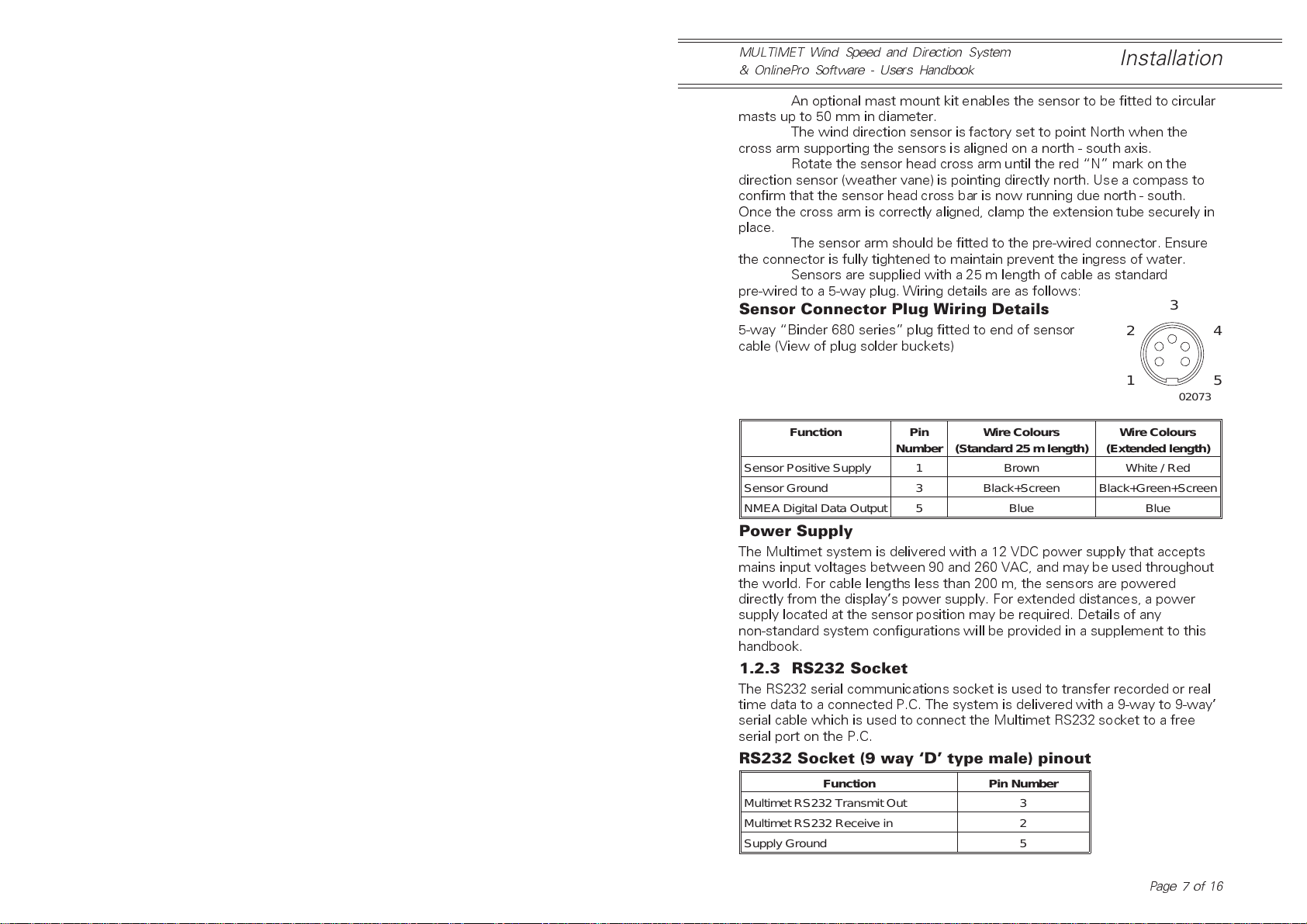
pre-wired to a 5-way plug. Wiring details are as follows:
Sensor Connector Plug Wiring Details
5-way Binder 680 series plug fitted to end of sensor
3
2
cable (View of plug solder buckets)
4
1
02073
Function Pin
Number
Sensor Positive Supply 1 Brown White / Red
Sensor Ground 3 Black+Screen Black+Green+Screen
NMEA Digital Data Output 5 Blue Blue
Wire Colours
(Standard 25 m length)
Wire Colours
(Extended length)
Power Supply
The Multimet system is delivered with a 12 VDC power supply that accepts
mains input voltages between 90 and 260 VAC, and may be used throughout
the world. For cable lengths less than 200 m, the sensors are powered
directly from the displays power supply. For extended distances, a power
supply located at the sensor position may be required. Details of any
non-standard system configurations will be provided in a supplement to this
handbook.
1.2.3 RS232 Socket
The RS232 serial communications socket is used to transfer recorded or real
time data to a connected P.C. The system is delivered with a 9-way to 9-way
serial cable which is used to connect the Multimet RS232 socket to a free
serial port on the P.C.
RS232 Socket (9 way ‘D’ type male) pinout
Function Pin Number
Multimet RS232 Transmit Out 3
Multimet RS232 Receive in 2
Supply Ground 5
5
Page 7 of 16
Page 8
Installation
MULTIMET Wind Speed and Direction System
& OnlinePro Software - Users Handbook
1.2.4 Expansion Socket
The Expansion socket provides signals used for CANTMbus display
networking and interfacing to an external alarm circuit.
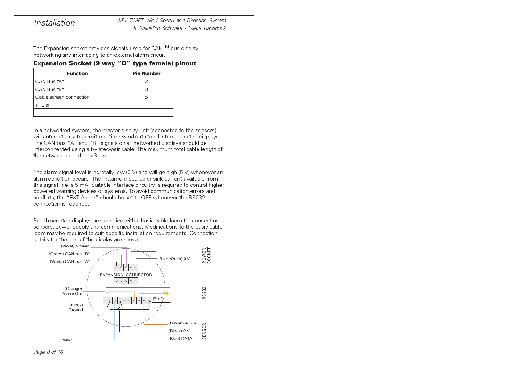
Expansion Socket (9 way “D” type female) pinout
Function Pin Number
CAN Bus “A” 2
CAN Bus “B” 3
Cable screen connection 5
TTL alarm output 9
Alarm ground 8
1.2.5 Networking Multiple Displays
In a networked system, the master display unit (connected to the sensors)
will automatically transmit real-time wind data to all interconnected displays.
The CAN bus A and B signals on all networked displays should be
interconnected using a twisted-pair cable. The maximum total cable length of
the network should be <3 km.
1.2.6 Alarm Output
The alarm signal level is normally low (0 V) and will go high (5 V) whenever an
alarm condition occurs. The maximum source or sink current available from
this signal line is 5 mA. Suitable interface circuitry is required to control higher
powered warning devices or systems. To avoid communication errors and
conflicts, the EXT Alarm should be set to OFF whenever the RS232
connection is required.
1.2.7 Wiring Details for Panel Mounted Displays
Panel mounted displays are supplied with a basic cable loom for connecting
sensors, power supply and communications. Modifications to the basic cable
loom may be required to suit specific installation requirements. Connection
details for the rear of the display are shown.
(Violet) Screen
(Green) CAN bus "B"
(White) CAN bus "A"
(Red/Centre pin) +12 V
(Black/Outer) 0 V
POWER
SOCKET
Page 8 of 16
(Orange)
Alarm Out
(Black)
Ground
02074
EXPANSION CONNECTOR
Pin1
(Blue) RX
(Yellow)TX
(Black) 0 V
(Brown) +12 V
(Black) 0 V
(Blue) DATA
RS232
SENSOR
Page 9
MULTIMET Wind Speed and Direction System
& OnlinePro Software - Users Handbook
Operating Multimet
2. OPERATING MULTIMET
2.1 Getting Started
When first switched on, the Multimet performs a series of self test routines
and displays the currently installed software version. Following successful
completion of these routines, a system prompt will request entry of the
current time and date.
It is important to set the current time and date correctly whenever
the internal data logging facility is used. This ensures that all recorded data is
correctly marked with corresponding date and time markers.
2.2 Setting the Time and Date
Adjustment of the time and date is performed using the appropriate grey
buttons located on the front of the instrument, immediately below each
option shown on the display.
The internal clock may also be set automatically from the Online Pro
P.C software, as described later.
It will be necessary to reset the clock whenever the power supply
has been disconnected from the system.
Following the entry of time and date, the display will present the
Main compass display containing 2 minute rolling average data.
2.2.1 Adjusting back light and contrast
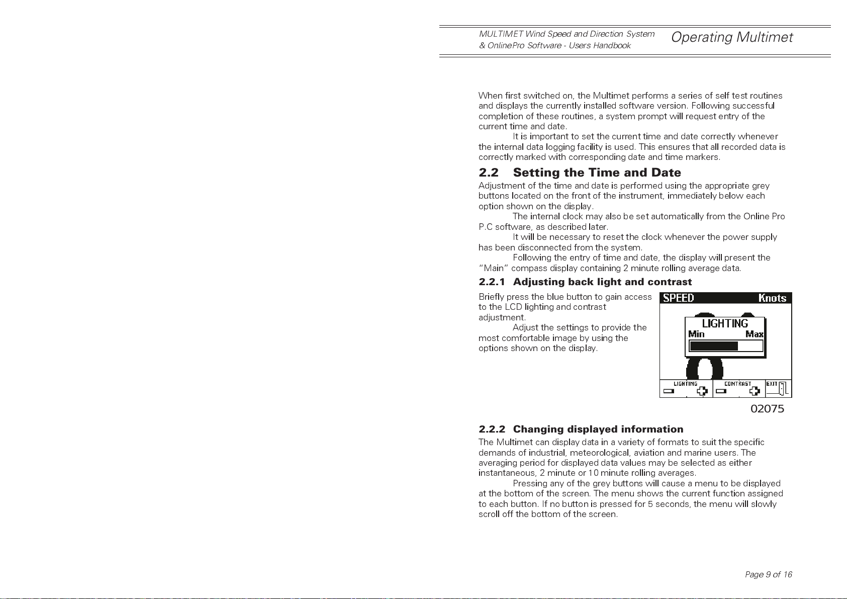
Briefly press the blue button to gain access
to the LCD lighting and contrast
adjustment.
Adjust the settings to provide the
most comfortable image by using the
options shown on the display.
02075
2.2.2 Changing displayed information
The Multimet can display data in a variety of formats to suit the specific
demands of industrial, meteorological, aviation and marine users. The
averaging period for displayed data values may be selected as either
instantaneous, 2 minute or 10 minute rolling averages.
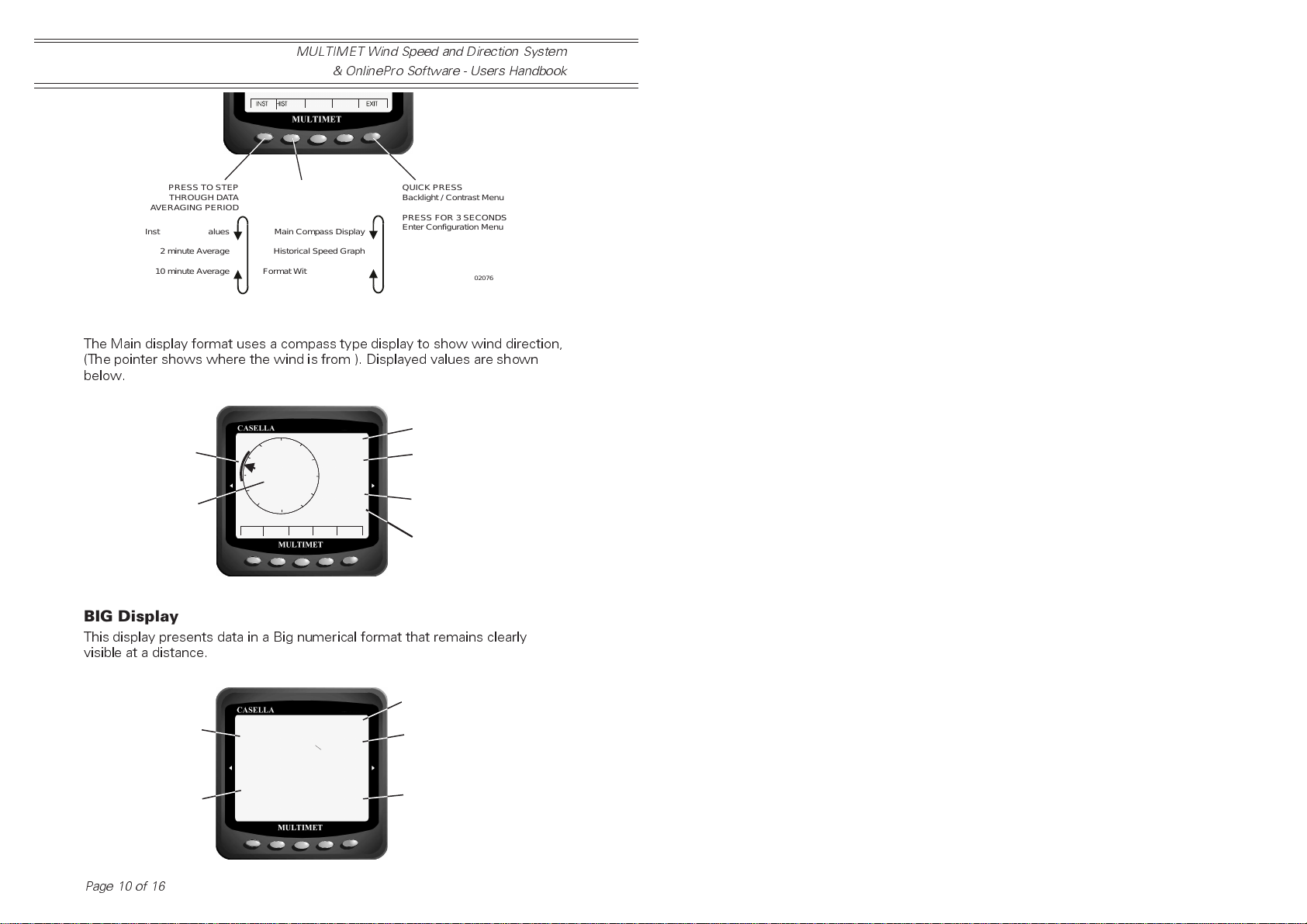
Pressing any of the grey buttons will cause a menu to be displayed
at the bottom of the screen. The menu shows the current function assigned
to each button. If no button is pressed for 5 seconds, the menu will slowly
scroll off the bottom of the screen.
Page 9 of 16
Page 10
Operating Multimet
MULTIMET Wind Speed and Direction System
& OnlinePro Software - Users Handbook
PRESS TOSTEP
THROUGH DATA
AVERAGING PERIOD
Instantaneous Values
2 minute Average
10 minute Average
PRESS TOSTEP
THROUGH DIFFERENT
DISPLAY FORMATS
Main CompassDisplay
Historical SpeedGraph
Format With Big Numbers
QUICK PRESS
Backlight / Contrast Menu
PRESS FOR 3 SECONDS
Enter ConfigurationMenu
02076
MAIN Wind Display
The Main display format uses a compass type display to show wind direction,
(The pointer shows where the wind is from ). Displayed values are shown
below.
VariationSector: the
limits of average direction
during averaging period
Averaged direction:
shown as both a value
and pointer position
02077
°
120
60
E
2 Min
12.6
Knots
Gust
Max 14.6
Min 10.6
N
N
330
330
30
30
300
300
W
W
280
240
210
150
S
S
13:45
INST HIST EXIT
Selected Averaging
period
Averaged wind speed
with measurement units
Wind Gust Warning
(shown when instant speed exceeds
the average by a preset threshold)
Max / Min Instantaneous speed
during averaging period
( ie, during last 2 minutes)
BIG Display
This display presents data in a Big numerical format that remains clearly
visible at a distance.
Instantaneous or
averaged direction
Instantaneous or
averaged speed with
measurement units
02078
Page 10 of 16
280
12.6
Knots
°
2 Min
Max 295
Min 255
Max 14.6
Min 10.6
Averaging period
°
°
Max and Min value of
instantaneous direction
during averaging period
Max and Min value of
instantaneous speed
during averaging period
Page 11
MULTIMET Wind Speed and Direction System
& OnlinePro Software - Users Handbook
Operating Multimet
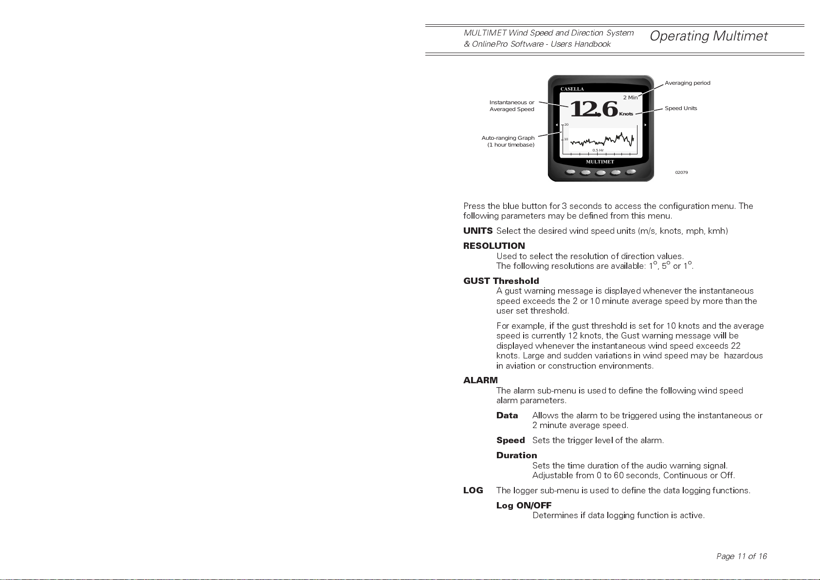
HISTORIC Wind Graph
Averaging period
Instantaneous or
Averaged Speed
Auto-ranging Graph
(1 hour timebase)
12.6
20
10
0.5 Hr
2 Min
Knots
Speed Units
02079
2.3 System Configuration Menu
Press the blue button for 3 seconds to access the configuration menu. The
following parameters may be defined from this menu.
UNITS
RESOLUTION
GUST Threshold
ALARM
LOG
Select the desired wind speed units (m/s, knots, mph, kmh)
Used to select the resolution of direction values.
The following resolutions are available: 1o,5oor 1o.
A gust warning message is displayed whenever the instantaneous
speed exceeds the 2 or 10 minute average speed by more than the
user set threshold.
For example, if the gust threshold is set for 10 knots and the average
speed is currently 12 knots, the Gust warning message will be
displayed whenever the instantaneous wind speed exceeds 22
knots. Large and sudden variations in wind speed may be hazardous
in aviation or construction environments.
The alarm sub-menu is used to define the following wind speed
alarm parameters.
Data
Allows the alarm to be triggered using the instantaneous or
2 minute average speed.
Speed
Sets the trigger level of the alarm.
Duration
Sets the time duration of the audio warning signal.
Adjustable from 0 to 60 seconds, Continuous or Off.
The logger sub-menu is used to define the data logging functions.
Log ON/OFF
Determines if data logging function is active.
Page 11 of 16
Page 12
Operating Multimet
MULTIMET Wind Speed and Direction System
& OnlinePro Software - Users Handbook
SYSTEM
Interval
Clear
A statistical summary of the loggers operating condition is shown at
the bottom of the screen. It is used to identify the number of
records saved in the memory, the remaining logging time available
(days, hours, minutes) before oldest data will be overwritten and also
the percentage of occupied memory space.
Once the memory becomes full of data, the logger will automatically
overwrite the oldest data records with new ones. This ensures the
most recent conditions are always being recorded.
The System menu contains the following less frequently used
configuration parameters.
PC Port
Reset All
Bleep ON/OFF
EXT Alarm ON/OFF
DEMO OFF
LANG English
Allows the logging interval to be adjusted from 1 to
120 minutes.
Used to erase any data saved within the internal memory.
Determines the RS232 communication speed (9600 default).
Provides a complete system reset, which is used to clear
the memory and reset date and time.
Determines if a bleep on keypress is required.
A logic level control signal is available for interfacing to
remote alarm circuitry. To avoid communication errors and
conflicts, the EXT Alarm should be set OFF whenever the
RS232 connection is required.
Creates random data for demonstration purposes only.
Sets the user interface language.
The currently supported language is English.
2.4 Alarm Operation
The wind speed alarm is triggered whenever the selected speed value
(instaneous or 2 min average) exceeds the preset threshold. The system will
bleep for the programmed time period (0-2 minutes, continuous or Off).
To swwitch the alarm sound off, press any key to reveal the menu
bar.
Pressing the central grey button will switch the alarm sound off.
Should the wind speed pass through the threshold again, the sound
will be re-triggered. The ALARM warning message will remain visible whilst
the alarm condition remains.
Page 12 of 16
Page 13
MULTIMET Wind Speed and Direction System
& OnlinePro Software - Users Handbook
PC Software
3. ONLINE PRO PC SOFTWARE
3.1 Software Overview
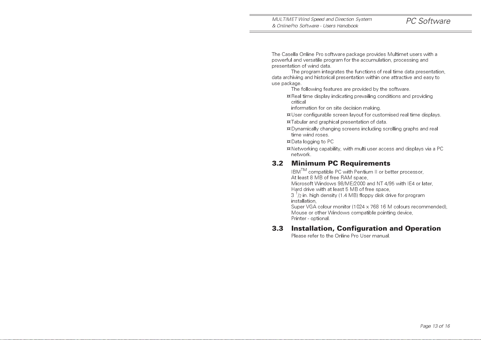
The Casella Online Pro software package provides Multimet users with a
powerful and versatile program for the accumulation, processing and
presentation of wind data.
The program integrates the functions of real time data presentation,
data archiving and historical presentation within one attractive and easy to
use package.
The following features are provided by the software.
¤
Real time display indicating prevailing conditions and providing
critical
information for on site decision making.
¤
User configurable screen layout for customised real time displays.
¤
Tabular and graphical presentation of data.
¤
Dynamically changing screens including scrolling graphs and real
time wind roses.
¤
Data logging to PC
¤
Networking capability, with multi user access and displays via a PC
network.
3.2 Minimum PC Requirements
IBMTMcompatible PC with Pentium II or better processor,
At least 8 MB of free RAM space,
Microsoft Windows 98/ME/2000 and NT 4/95 with IE4 or later,
Hard drive with at least 5 MB of free space,
31/2in. high density (1.4 MB) floppy disk drive for program
installation,
Super VGA colour monitor (1024 x 768 16 M colours recommended),
Mouse or other Windows compatible pointing device,
Printer - optional.
3.3 Installation, Configuration and Operation
Please refer to the Online Pro User manual.
Page 13 of 16
Page 14
Maintenance
MULTIMET Wind Speed and Direction System
& OnlinePro Software - Users Handbook
4. MAINTENANCE AND SERVICE
4.1 Routine Maintenance
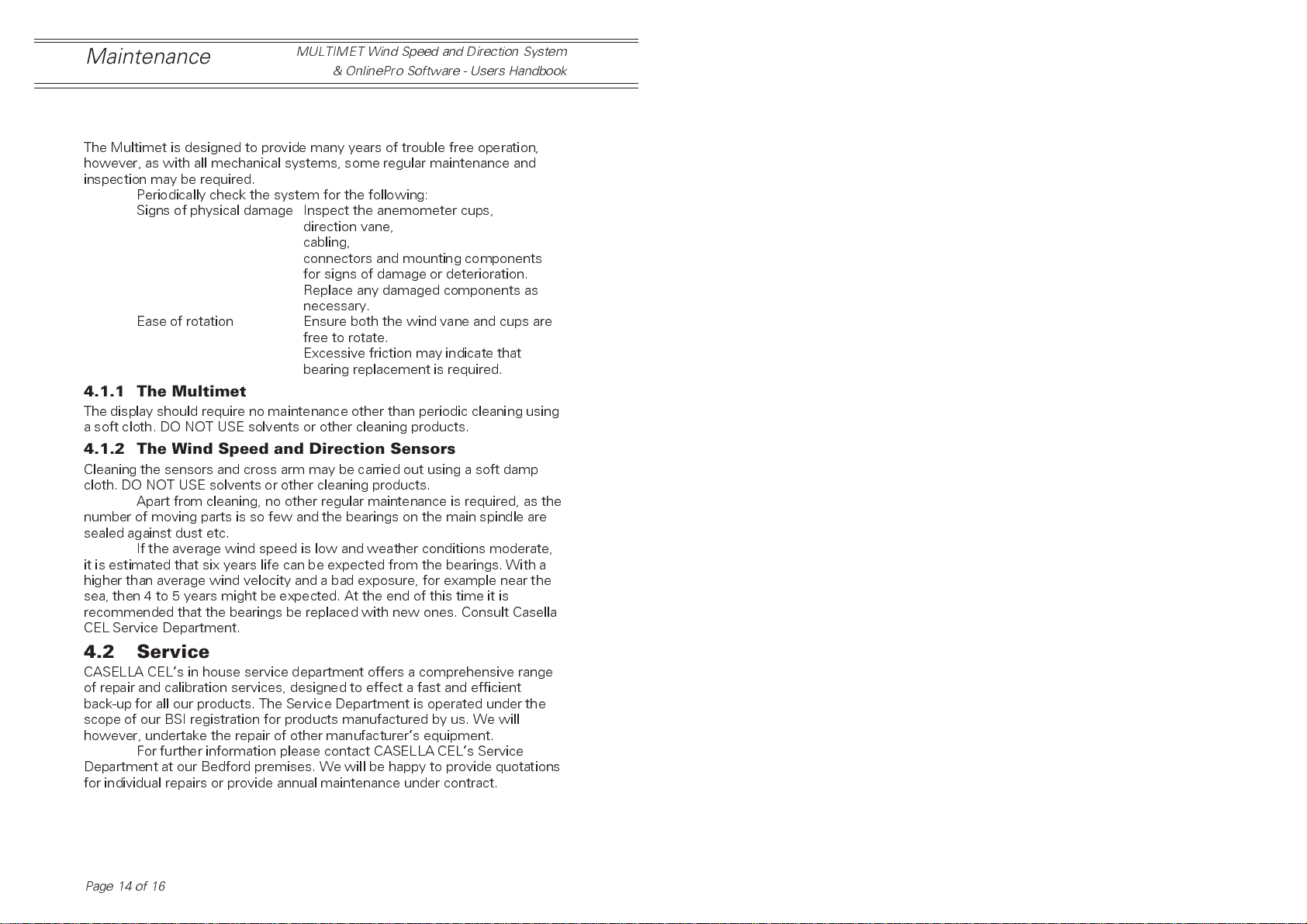
The Multimet is designed to provide many years of trouble free operation,
however, as with all mechanical systems, some regular maintenance and
inspection may be required.
Periodically check the system for the following:
Signs of physical damage Inspect the anemometer cups,
direction vane,
cabling,
connectors and mounting components
for signs of damage or deterioration.
Replace any damaged components as
necessary.
Ease of rotation Ensure both the wind vane and cups are
free to rotate.
Excessive friction may indicate that
bearing replacement is required.
4.1.1 The Multimet
The display should require no maintenance other than periodic cleaning using
a soft cloth. DO NOT USE solvents or other cleaning products.
4.1.2 The Wind Speed and Direction Sensors
Cleaning the sensors and cross arm may be carried out using a soft damp
cloth. DO NOT USE solvents or other cleaning products.
Apart from cleaning, no other regular maintenance is required, as the
number of moving parts is so few and the bearings on the main spindle are
sealed against dust etc.
If the average wind speed is low and weather conditions moderate,
it is estimated that six years life can be expected from the bearings. With a
higher than average wind velocity and a bad exposure, for example near the
sea, then 4 to 5 years might be expected. At the end of this time it is
recommended that the bearings be replaced with new ones. Consult Casella
CEL Service Department.
4.2 Service
CASELLA CELs in house service department offers a comprehensive range
of repair and calibration services, designed to effect a fast and efficient
back-up for all our products. The Service Department is operated under the
scope of our BSI registration for products manufactured by us. We will
however, undertake the repair of other manufacturers equipment.
For further information please contact CASELLA CELs Service
Department at our Bedford premises. We will be happy to provide quotations
for individual repairs or provide annual maintenance under contract.
Page 14 of 16
Page 15
MULTIMET Wind Speed and Direction System
& OnlinePro Software - Users Handbook
Specifications
5. SPECIFICATIONS
5.1 Anemometer Wind Speed Sensor
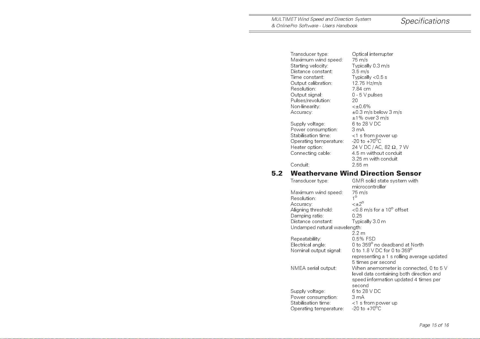
Transducer type: Optical interrupter
Maximum wind speed: 75 m/s
Starting velocity: Typically 0.3 m/s
Distance constant: 3.5 m/s
Time constant: Typically <0.5 s
Output calibration: 12.75 Hz/m/s
Resolution: 7.84 cm
Output signal: 0 - 5 V pulses
Pulses/revolution: 20
Non-linearity: <±0.6%
Accuracy: ±0.3 m/s below 3 m/s
±1% over 3 m/s
Supply voltage: 6 to 28 V DC
Power consumption: 3 mA
Stabilisation time: <1 s from power up
Operating temperature: -20 to +70oC
Heater option: 24 V DC / AC, 82Ω,7W
Connecting cable: 4.5 m without conduit
3.25 m with conduit
Conduit: 2.55 m
5.2 Weathervane Wind Direction Sensor
Transducer type: GMR solid state system with
microcontroller
Maximum wind speed: 75 m/s
Resolution: 1
Accuracy: <±2
Aligning threshold: <0.8 m/s for a 10ooffset
Damping ratio: 0.25
Distance constant: Typically 3.0 m
Undamped natural wavelength:
Repeatability: 0.5% FSD
Electrical angle: 0 to 359ono deadband at North
Nominal output signal: 0 to 1.8 V DC for 0 to 359
NMEA serial output: When anemometer is connected, 0 to 5 V
Supply voltage: 6 to 28 V DC
Power consumption: 3 mA
Stabilisation time: <1 s from power up
Operating temperature: -20 to +70oC
o
o
2.2 m
o
representing a 1 s rolling average updated
5 times per second
level data containing both direction and
speed information updated 4 times per
second
Page 15 of 16
Page 16
Specifications
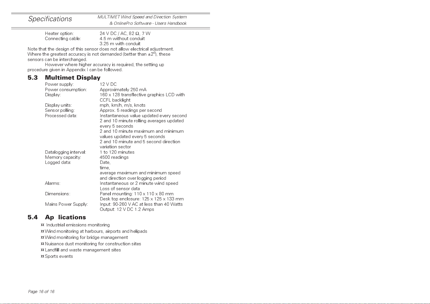
Heater option: 24 V DC / AC, 82Ω,7W
Connecting cable: 4.5 m without conduit
Note that the design of this sensor does not allow electrical adjustment.
Where the greatest accuracy is not demanded (better than ±2o), these
sensors can be interchanged.
However where higher accuracy is required, the setting up
procedure given in Appendix I can be followed.
MULTIMET Wind Speed and Direction System
& OnlinePro Software - Users Handbook
3.25 m with conduit
5.3 Multimet Display
Power supply: 12 V DC
Power consumption: Approximately 250 mA
Display: 160 x 128 transflective graphics LCD with
CCFL backlight
Display units: mph, km/h, m/s, knots
Sensor polling: Approx. 5 readings per second
Processed data: Instantaneous value updated every second
2 and 10 minute rolling averages updated
every 5 seconds
2 and 10 minute maximum and minimum
values updated every 5 seconds
2 and 10 minute and 5 second direction
variation sector
Datalogging interval: 1 to 120 minutes
Memory capacity: 4500 readings
Logged data: Date,
time,
average maximum and minimum speed
and direction over logging period
Alarms: Instantaneous or 2 minute wind speed
Loss of sensor data
Dimensions: Panel mounting: 110 x 110 x 80 mm
Desk top enclosure: 125 x 125 x 133 mm
Mains Power Supply: Input: 90-260 V AC at less than 40 Watts
Output: 12 V DC 1.2 Amps
5.4 Applications
Industrial emissions monitoring
¤
¤
Wind monitoring at harbours, airports and helipads
¤
Wind monitoring for bridge management
¤
Nuisance dust monitoring for construction sites
¤
Landfill and waste management sites
¤
Sports events
Page 16 of 16
 Loading...