

Page 1
VORTEX Ultra Flow & Ultra Flow lite
SAMPLING PUMPS Handbook
VORTEX Ultra Flow &
VORTEX Ultra Flow lite
SAMPLING PUMPS
User Manual
HB 3269-05
COPYRIGHT
July 2000
The copyright in this document which contains proprietary information is vested in
CASELLA CEL. The contents of this document must not be used for purposes other
than that for which it has been supplied or reproduced or disclosed wholly or in part
without the prior written permission of
CASELLA CEL
CASELLA CEL
Regent House
Wolseley Road
Kempston
Bedford
MK42 7JY, United kingdom
Phone: +44 (0) 1234 844 100
Fax: +44 (0) 1234 841 490
E-mail info@casellagroup.com
Web: www.casellagroup.com
CASELLA USA
17 Old Nashua Road #15
Amherst
NH 03031
U.S.A.
Toll Free: +1 800 366 2966
Fax: +1 603 672 8053
E-mail info@casellaUSA.com
Web: www.casellaUSA.com
Page 2
Contents
VORTEX Ultra Flow & Ultra Flow lite
SAMPLING PUMPS Handbook
TABLE OF CONTENTS
CONTENTS ................PAGE
1. INTRODUCTION . . . . . . . . . . . . . . . . . . . . . . . . . . . 3
2. OPERATION . . . . . . . . . . . . . . . . . . . . . . . . . . . . . 4
2.1 Battery . . . . . . . . . . . . . . . . . . . . . . . . . . . 4
2.2 Battery Low Shutdown . . . . . . . . . . . . . . . . . . 4
2.3 Switching the Pump ON and OFF . . . . . . . . . . . . . 5
2.4 IndicatorLEDS.......................5
2.5 Flow Adjustment . . . . . . . . . . . . . . . . . . . . . . 6
2.6 Flow Compensation . . . . . . . . . . . . . . . . . . . . 6
2.7 Flow Shut Down Adjustment . . . . . . . . . . . . . . 6
2.8 Timer............................7
2.9 Table of Functionality . . . . . . . . . . . . . . . . . . . . 7
3. SAMPLING . . . . . . . . . . . . . . . . . . . . . . . . . . . . . 8
3.1 Check List Before Sampling . . . . . . . . . . . . . . . . 8
4 SERVICING . . . . . . . . . . . . . . . . . . . . . . . . . . . . . 9
5. FAULT FINDING . . . . . . . . . . . . . . . . . . . . . . . . . . 10
6. TECHNICAL SPECIFICATIONS
6.1 Ultra Flow . . . . . . . . . . . . . . . . . . . . . . . . 11
6.2 Ultra Flow
6.3 Additional Features . . . . . . . . . . . . . . . . . . . . 11
7. OPTIONAL ACCESSORIES . . . . . . . . . . . . . . . . . . . . 12
Page 2 of 12
lite
...................... 11
Page 3
VORTEX Ultra Flow & Ultra Flow lite
SAMPLING PUMPS Handbook
Introduction
1. INTRODUCTION
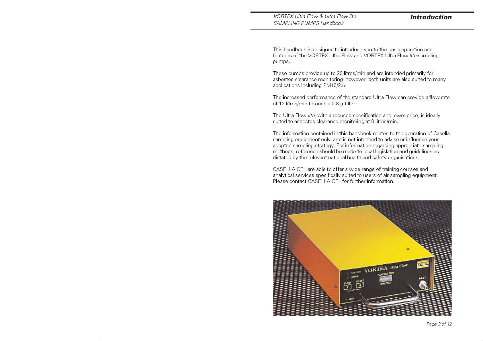
This handbook is designed to introduce you to the basic operation and
features of the VORTEX Ultra Flow and VORTEX Ultra Flow
pumps.
These pumps provide up to 20 litres/min and are intended primarily for
asbestos clearance monitoring, however, both units are also suited to many
applications including PM10/2.5.
The increased performance of the standard Ultra Flow can provide a flow rate
of 12 litres/min through a 0.8µfilter.
lite
sampling
The Ultra Flow
suited to asbestos clearance monitoring at 8 litres/min.
The information contained in this handbook relates to the operation of Casella
sampling equipment only, and is not intended to advise or influence your
adopted sampling strategy. For information regarding appropriate sampling
methods, reference should be made to local legislation and guidelines as
dictated by the relevant national health and safety organisations.
CASELLA CEL are able to offer a wide range of training courses and
analytical services specifically suited to users of air sampling equipment.
Please contact CASELLA CEL for further information.
lite,
with a reduced specification and lower price, is ideally
Page 3 of 12
Page 4
Operation
VORTEX Ultra Flow & Ultra Flow lite
SAMPLING PUMPS Handbook
2. OPERATION
Both designs utilise a twin diaphragm pump to reduce pulsations in airflow
and maintain high efficiency. Precise control of the sample flow rate is
achieved using a current proportional feed back technique.
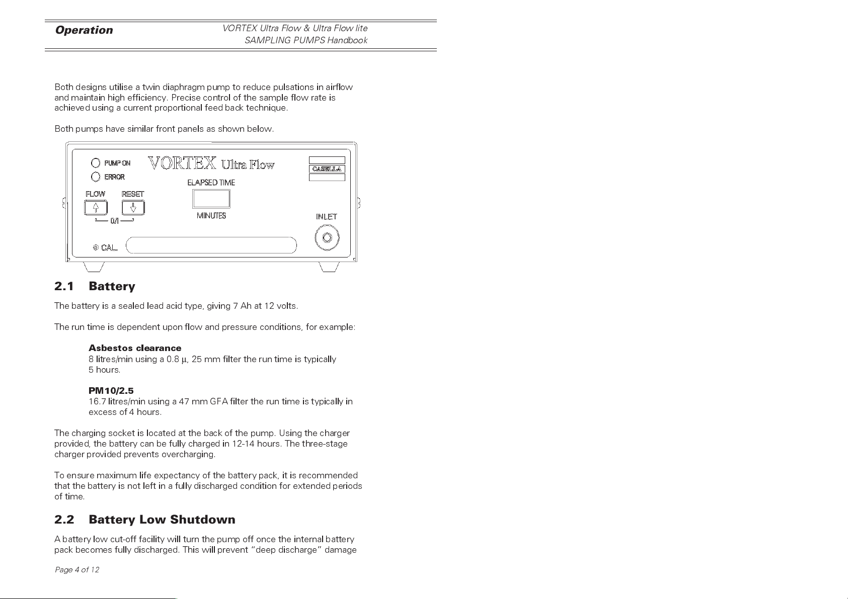
Both pumps have similar front panels as shown below.
2.1 Battery
The battery is a sealed lead acid type, giving 7 Ah at 12 volts.
The run time is dependent upon flow and pressure conditions, for example:
Asbestos clearance
8 litres/min using a 0.8µ, 25 mm filter the run time is typically
5 hours.
PM10/2.5
16.7 litres/min using a 47 mm GFA filter the run time is typically in
excess of 4 hours.
The charging socket is located at the back of the pump. Using the charger
provided, the battery can be fully charged in 12-14 hours. The three-stage
charger provided prevents overcharging.
To ensure maximum life expectancy of the battery pack, it is recommended
that the battery is not left in a fully discharged condition for extended periods
of time.
2.2 Battery Low Shutdown
A battery low cut-off facility will turn the pump off once the internal battery
pack becomes fully discharged. This will prevent deep discharge damage
Page 4 of 12
Page 5
VORTEX Ultra Flow & Ultra Flow lite
SAMPLING PUMPS Handbook
and ensures maximum life of the battery pack. Should the pump be
switched on with a discharged battery, battery low warning bleeps will be
given prior to the pump shutting itself down.
Operation
2.3 Switching the Pump ON and OFF
To switch the pump ON, press the FLOW and RESET keys at the same
time. The buzzer will bleep twice and the green PUMP ON LED will be lit,
indicating that the pump is switched on and running.
To switch the pump OFF, press the FLOW and RESET keys at the same
time.
2.4 Indicator LEDs
There are two light emitting diodes (LEDs) located on the front panel of the
instrument.
PUMP ON
Green Indicator: used to indicate that the pump is switched ON and is
running. The LED flashes when in flow adjustment mode.
ERROR
Red indicator: used to identify one of two potential error conditions.
Battery Low Warning
When the battery approaches a discharged condition, the red
ERROR LED flashes slowly. Sampling should be terminated and
the battery recharged.
Flow Fault Shut Down
The red ERROR LED flashes rapidly whenever the pumps loading
exceeds a pre-set value. This may be due to excessive back
pressure from a tube restriction, filter blockage, or pump fault.
Should the fault condition remain for 8 seconds then the pump will
automatically shut down and the ERROR LED will remain lit. The
timer display will retain the present value enabling a valid sample
volume to be calculated from the indicated elapsed time and the
initial flow rate.
Pressing both keys will cancel the error warning.
Page 5 of 12
Page 6
Operation
VORTEX Ultra Flow & Ultra Flow lite
SAMPLING PUMPS Handbook
2.5 Flow Adjustment
Adjust the pump flow to the desired rate while the pump is running.
1. Press the FLOW key for 3 seconds, the green PUMP ON LED will
flash.
2. Temporarily release the key, the green LED will continue to flash
while the pump is in this mode.
3. Adjust the flow rate, either up or down, by holding down the
appropriate key, the adjustment is slow to start then picks up speed.
4. If there is no key press after 4 seconds, the pump will return to
normal run mode and the green PUMP ON LED will stop flashing.
For optimum stability of flow, it may be necessary to allow the pump to run
for a few minutes before use.
2.6 Flow Compensation
Both versions of the Ultra Flow are factory calibrated to maintain stable flow
at 8 litres/min. At different flow rates it may be necessary to adjust the front
panel CAL control to ensure stable flow rate over varying pressure
conditions.
If the flow drops as pressure increases, increase the flow using the CAL
adjustment and then reduce the flow back to the desired flow rate using the
front panel keys.
If an increase in applied pressure drop causes the sample flow rate to
increase, decrease the flow using the CAL adjustment and then increase
the flow back to the desired flow rate using the front panel, up/down, keys.
Repeat the CAL adjustments until the sample flow rate remains constant
over the operating pressure range.
2.7 Flow “Shut Down” Adjustment
Sometimes it is necessary to adjust the flow shut down level to suit the
sampling flow rate and pressure drop conditions.
1. With the pump switched off, undo the four retaining screws and
remove the lid.
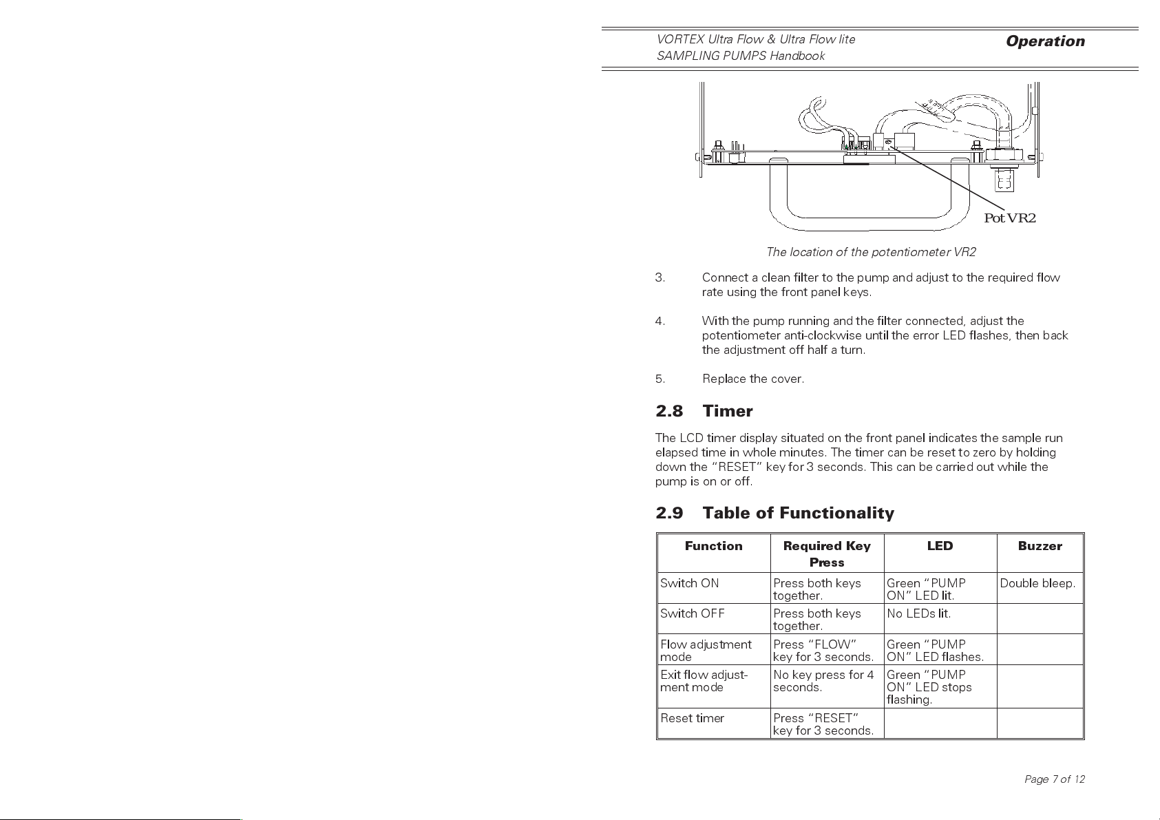
2. Adjust the potentiometer VR2, in the middle at the bottom of the
circuit board (see figure opposite), fully clockwise, until it clicks.
Page 6 of 12
Page 7
VORTEX Ultra Flow & Ultra Flow lite
SAMPLING PUMPS Handbook
Operation
Pot VR2
The location of the potentiometer VR2
3. Connect a clean filter to the pump and adjust to the required flow
rate using the front panel keys.
4. With the pump running and the filter connected, adjust the
potentiometer anti-clockwise until the error LED flashes, then back
the adjustment off half a turn.
5. Replace the cover.
2.8 Timer
The LCD timer display situated on the front panel indicates the sample run
elapsed time in whole minutes. The timer can be reset to zero by holding
down the RESET key for 3 seconds. This can be carried out while the
pump is on or off.
2.9 Table of Functionality
Function Required Key
Press
Switch ON Press both keys
Switch OFF Press both keys
Flow adjustment
mode
Exit flow adjust-
ment mode
Reset timer Press RESET
together.
together.
Press FLOW
key for 3 seconds.
No key press for 4
seconds.
key for 3 seconds.
LED Buzzer
Green PUMP
ON LED lit.
No LEDs lit.
Green PUMP
ON LED flashes.
Green PUMP
ON LED stops
flashing.
Double bleep.
Page 7 of 12
Page 8
Operation
VORTEX Ultra Flow & Ultra Flow lite
SAMPLING PUMPS Handbook
3. SAMPLING
Asbestos clearance procedures can be found in MDHS 39.
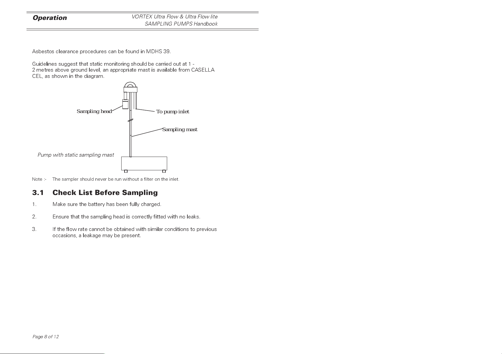
Guidelines suggest that static monitoring should be carried out at 1 -
2 metres above ground level, an appropriate mast is available from CASELLA
CEL, as shown in the diagram.
Sampling head
Topump inlet
Sampling mast
Pump with static sampling mast
Note :- The sampler should never be run without a filter on the inlet.
3.1 Check List Before Sampling
1. Make sure the battery has been fully charged.
2. Ensure that the sampling head is correctly fitted with no leaks.
3. If the flow rate cannot be obtained with similar conditions to previous
occasions, a leakage may be present.
Page 8 of 12
Page 9
VORTEX Ultra Flow & Ultra Flow lite
SAMPLING PUMPS Handbook
Servicing
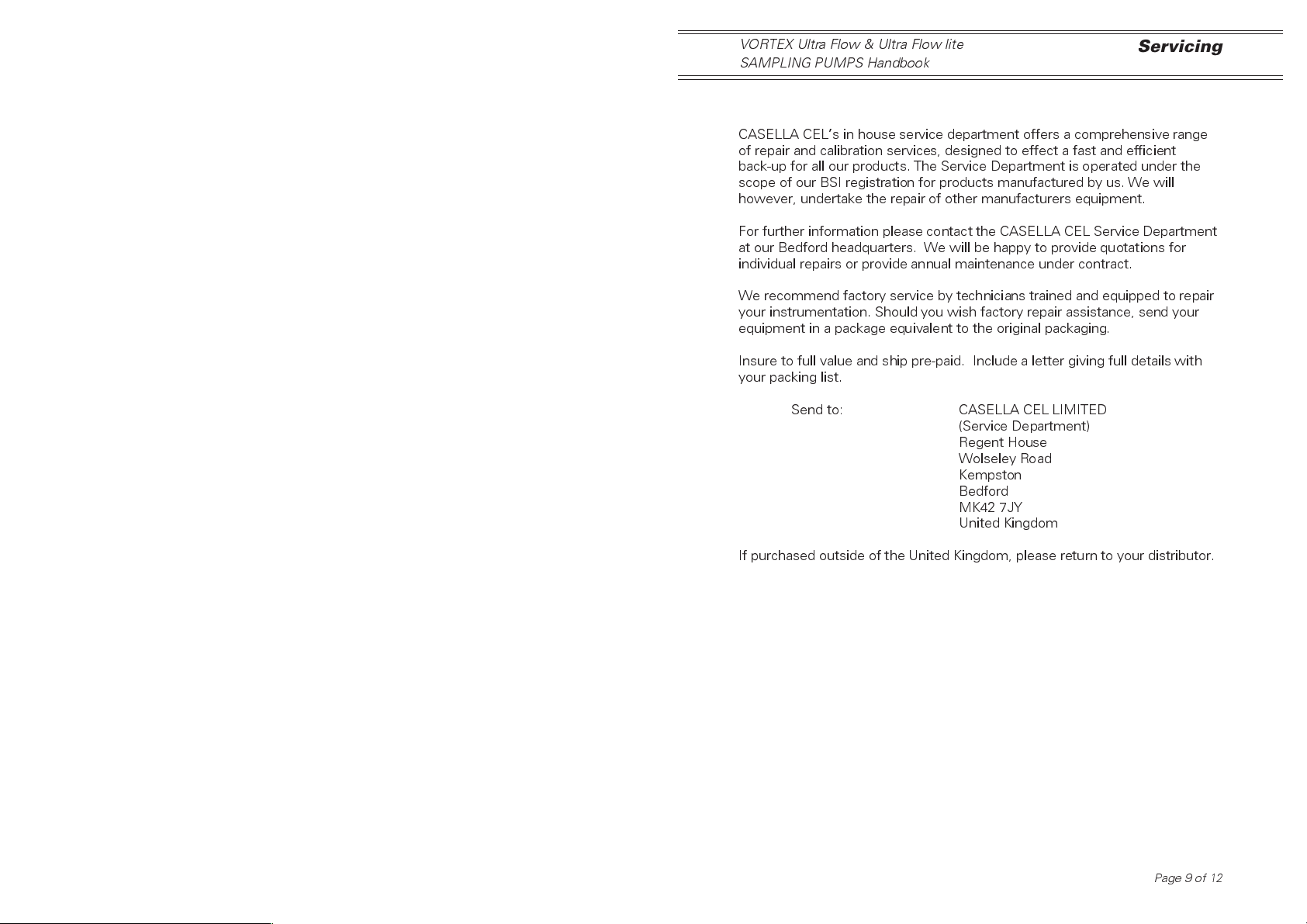
4. SERVICING
CASELLA CELs in house service department offers a comprehensive range
of repair and calibration services, designed to effect a fast and efficient
back-up for all our products. The Service Department is operated under the
scope of our BSI registration for products manufactured by us. We will
however, undertake the repair of other manufacturers equipment.
For further information please contact the CASELLA CEL Service Department
at our Bedford headquarters. We will be happy to provide quotations for
individual repairs or provide annual maintenance under contract.
We recommend factory service by technicians trained and equipped to repair
your instrumentation. Should you wish factory repair assistance, send your
equipment in a package equivalent to the original packaging.
Insure to full value and ship pre-paid. Include a letter giving full details with
your packing list.
Send to: CASELLA CEL LIMITED
(Service Department)
Regent House
Wolseley Road
Kempston
Bedford
MK42 7JY
United Kingdom
If purchased outside of the United Kingdom, please return to your distributor.
Page 9 of 12
Page 10
Fault Finding
VORTEX Ultra Flow & Ultra Flow lite
SAMPLING PUMPS Handbook
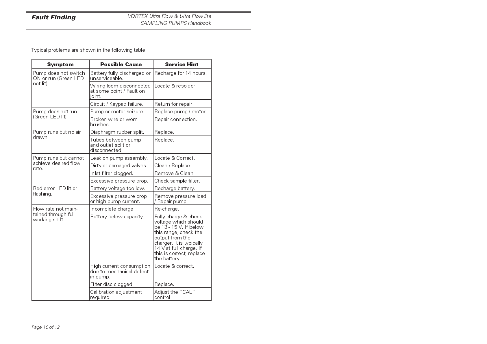
5. FAULT FINDING
Typical problems are shown in the following table.
Symptom Possible Cause Service Hint
Pump does not switch
ON or run (Green LED
not lit).
Pump does not run
(Green LED lit).
Pump runs but no air
drawn.
Pump runs but cannot
achieve desired flow
rate.
Red error LED lit or
flashing.
Flow rate not main-
tained through full
working shift.
Battery fully discharged or
unserviceable.
Wiring loom disconnected
at some point / Fault on
joint.
Circuit / Keypad failure. Return for repair.
Pump or motor seizure. Replace pump / motor.
Broken wire or worn
brushes.
Diaphragm rubber split. Replace.
Tubes between pump
and outlet split or
disconnected.
Leak on pump assembly. Locate & Correct.
Dirty or damaged valves. Clean / Replace.
Inlet filter clogged. Remove & Clean.
Excessive pressure drop. Check sample filter.
Battery voltage too low. Recharge battery.
Excessive pressure drop
or high pump current.
Incomplete charge. Re-charge.
Battery below capacity. Fully charge & check
High current consumption
due to mechanical defect
in pump.
Filter disc clogged. Replace.
Calibration adjustment
required.
Recharge for 14 hours.
Locate & resolder.
Repair connection.
Replace.
Remove pressure load
/ Repair pump.
voltage which should
be13-15V.Ifbelow
this range, check the
output from the
charger. It is typically
14 V at full charge. If
this is correct, replace
the battery.
Locate & correct.
Adjust the CAL
control
Page10of12
Page 11
VORTEX Ultra Flow & Ultra Flow lite
SAMPLING PUMPS Handbook
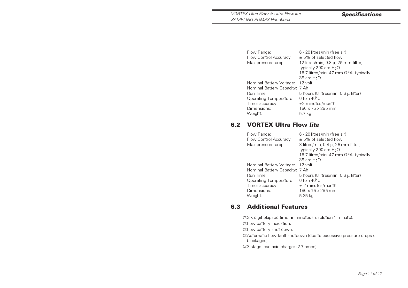
6. TECHNICAL SPECIFICATIONS
6.1 VORTEX Ultra Flow
Flow Range: 6 - 20 litres/min (free air)
Flow Control Accuracy: ± 5% of selected flow
Max pressure drop: 12 litres/min, 0.8µ, 25 mm filter,
typically 200 cm H2O
16.7 litres/min, 47 mm GFA, typically
35 cm H2O
Nominal Battery Voltage: 12 volt
Nominal Battery Capacity: 7 Ah
Run Time: 5 hours (8 litres/min, 0.8µfilter)
Operating Temperature: 0 to +40oC
Timer accuracy: ±2 minutes/month
Dimensions: 180 x 75 x 285 mm
Weight: 5.7 kg
6.2 VORTEX Ultra Flow lite
Flow Range: 6 - 20 litres/min (free air)
Flow Control Accuracy: ± 5% of selected flow
Max pressure drop: 8 litres/min, 0.8µ, 25 mm filter,
typically 200 cm H2O
16.7 litres/min, 47 mm GFA, typically
35 cm H2O
Nominal Battery Voltage: 12 volt
Nominal Battery Capacity: 7 Ah
Run Time: 5 hours (8 litres/min, 0.8µfilter)
Operating Temperature: 0 to +40oC
Timer accuracy: ± 2 minutes/month
Dimensions: 180 x 75 x 285 mm
Weight: 5.25 kg
Specifications
6.3 Additional Features
Six digit elapsed timer in minutes (resolution 1 minute).
¤
¤
Low battery indication.
¤
Low battery shut down.
¤
Automatic flow fault shutdown (due to excessive pressure drops or
blockages).
¤
3 stage lead acid charger (2.7 amps).
Page 11 of 12
Page 12
Optional Accessories
VORTEX Ultra Flow & Ultra Flow lite
SAMPLING PUMPS Handbook
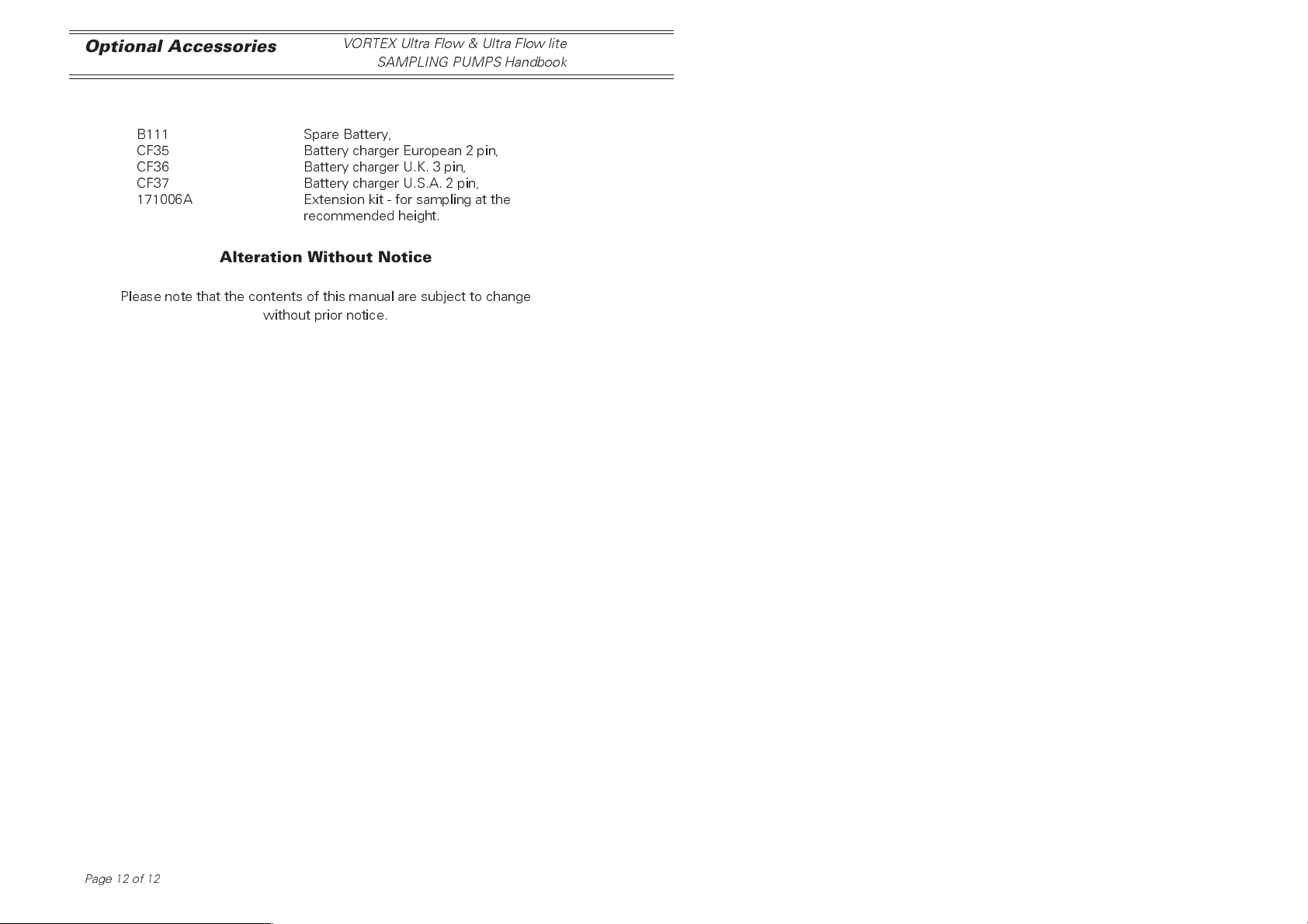
7, OPTIONAL ACCESSORIES
B111 Spare Battery,
CF35 Battery charger European 2 pin,
CF36 Battery charger U.K. 3 pin,
CF37 Battery charger U.S.A. 2 pin,
171006A Extension kit - for sampling at the
recommended height.
Alteration Without Notice
Please note that the contents of this manual are subject to change
without prior notice.
Page12of12
 Loading...