

Page 1
Getting Started With
CEL-553, CEL-573 & CEL-593
Sound Level Analysers
“Series 3”
1. Introduction
Issue: 6
Series 3 of the CEL-500 analysers
introduces a new instrument: the CEL-553
which is available ONLY as a real-time
third-octave sound level meter, with user
initiated storage of screen data.
Instruments in Series 3 can measure
noise levels, calculate the commonly
required time averaged parameters and
save the results.
The standard memory is capable of
storing about 200 000 data points, which is
equivalent to 6 000 data screens while the
optional extended memory can store
approximately 1 000 000 data points,
equivalent to 30 000 data screens.
Depending on model they can also
analyse and store noise data in broadband
and octave bands.
With the exception of the CEL-553
which has only SLM mode, the standard
versions of these instruments can be
operated in three different ways
(measurement modes) as follows.
¤
Real time sound level meter with user
initiated storage of screen data.
¤
Event sound level meter with manual,
remote or threshold triggering
(CEL-593 only).
¤
Environmental sound level meter with
user selected sampling periods
(CEL-573 and CEL-593).
The measurement parameters available on
standard versions vary from model to
model and from mode to mode as shown
in Table 1 on page 73.
To simplify measurement procedures,
pre-programmed setups are stored by the
instrument. There is a separate directory
for each application, mode and bandwidth,
each of which contains one initial setup
provided by the factory, and up to six more
defined by the user. Similarly, stored data
can be accessed via separate directories
for each bandwidth, or via an additional
directory that includes ALL data.
The following additional measurement
applications can be installed.
¤
Fastore capability that samples and
saves data at very short time intervals.
¤
Building Acoustics.
¤
Loudness Determination.
Each instrument in the series can be up-
(or down-) graded to any other model, to
include more (or fewer) features. Consult
your local agency or CEL for details.
Series 3 instruments with Version 7
and later firmware feature a revised
startup sequence where Application,
Acquisition Mode and Bandwidth are
selected via separate menu screens, plus
the option of measuring sound exposure
level (SEL) in broadband SLM and a
revised keypad appearance.
For a description of all CEL-500 series
instruments, also refer to the Reference
Handbook.
Getting Started - CEL-553/573/593 - Page 59
Page 2
2. Menus & Controls
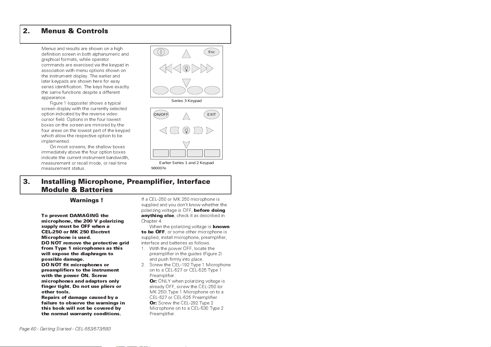
Menus and results are shown on a high
definition screen in both alphanumeric and
graphical formats, while operator
commands are exercised via the keypad in
association with menu options shown on
the instrument display. The earlier and
later keypads are shown here for easy
series identification. The keys have exactly
the same functions despite a different
appearance.
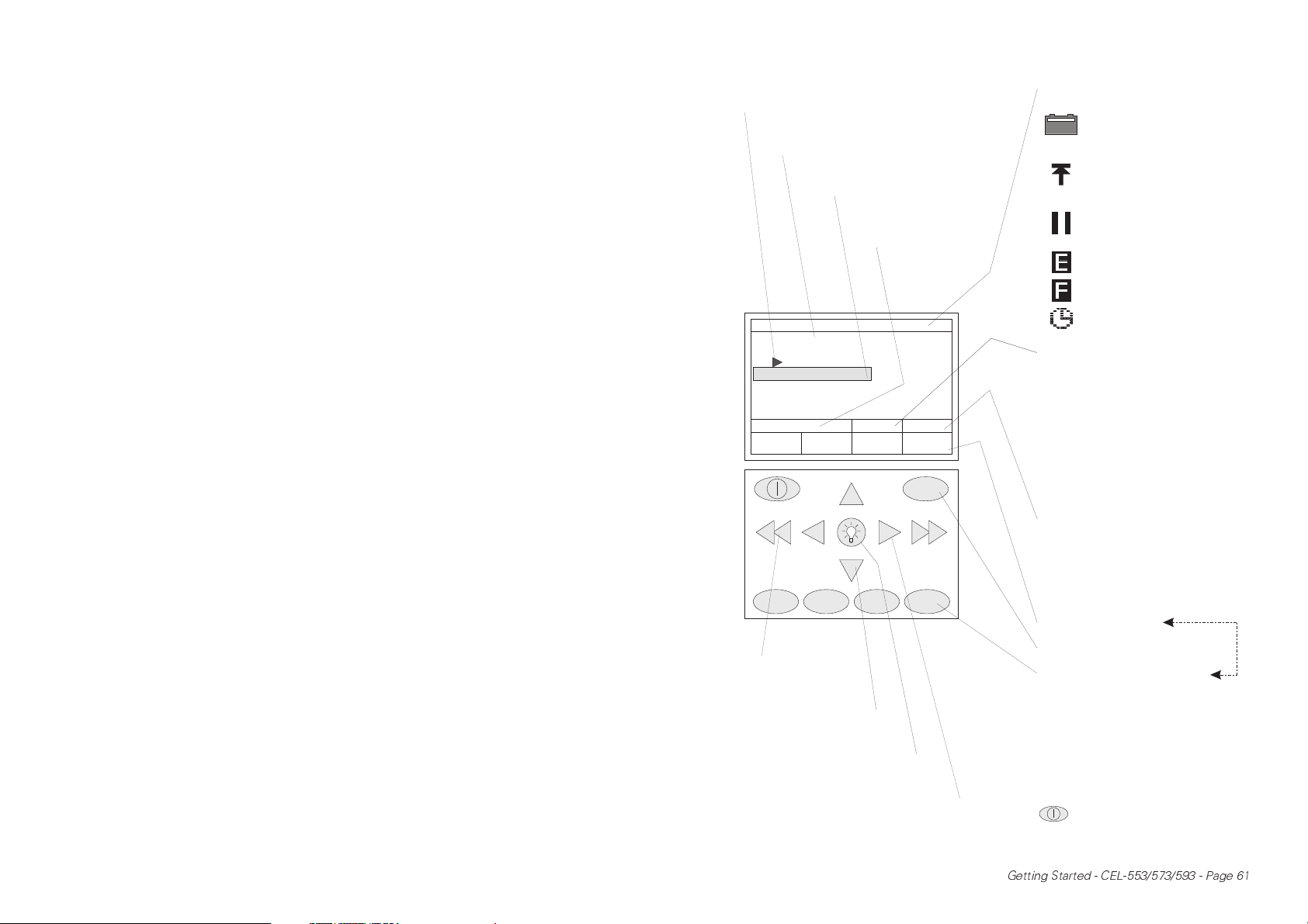
Figure 1 (opposite) shows a typical
screen display with the currently selected
option indicated by the reverse video
cursor field. Options in the four lowest
boxes on the screen are mirrored by the
four areas on the lowest part of the keypad
which allow the respective option to be
implemented.
On most screens, the shallow boxes
immediately above the four option boxes
indicate the current instrument bandwidth,
measurement or recall mode, or real time
measurement status.
ON/OFF
980007e
Series 3 Keypad
Earlier Series 1 and 2 Keypad
3. Installing Microphone, Preamplifier, Interface
Module & Batteries
Warnings !
To prevent DAMAGING the
microphone, the 200 V polarizing
supply must be OFF when a
CEL-250 or MK 250 Electret
Microphone is used.
DO NOT remove the protective grid
from Type 1 microphones as this
will expose the diaphragm to
possible damage.
DO NOT fit microphones or
preamplifiers to the instrument
with the power ON. Screw
microphones and adaptors only
finger tight. Do not use pliers or
other tools.
Repairs of damage caused by a
failure to observe the warnings in
this book will not be covered by
the normal warranty conditions.
If a CEL-250 or MK 250 microphone is
supplied and you dont know whether the
polarizing voltage is OFF,
anything else
Chapter 4.
When the polarizing voltage is
to be OFF
supplied, install microphone, preamplifier,
interface and batteries as follows.
1. With the power OFF, locate the
preamplifier in the guides (Figure 2)
and push firmly into place.
2. Screw the CEL-192 Type 1 Microphone
on to a CEL-527 or CEL-525 Type 1
Preamplifier.
Or:
already OFF, screw the CEL-250 (or
MK 250) Type 1 Microphone on to a
CEL-527 or CEL-525 Preamplifier.
Or:
Microphone on to a CEL-530 Type 2
Preamplifier.
, check it as described in
, or some other microphone is
ONLY when polarizing voltage is
Screw the CEL-292 Type 2
before doing
Esc
EXIT
known
Page 60 - Getting Started - CEL-553/573/593
Page 3
Indicates set up loaded by
C
a
i
default when switched ON
Non-deletable set up
provided by factory
Reverse video cursor
shows selected item
Current retrieve mode/
status/record number
will be shown here
Current status/screen title/narrow band
cursor status/message icons
Battery condition, icon
empties as power is drained.
When empty at 6.4 V, icon
blinks
Overload has occurred: is
removed from SLM screens
after 2 s, remains on EVT,
ENV and FST screens
Pause has occurred during
measurement or PAUSE
key pressed
Event capture is following an
event
Fastore is following an event
SETUP
1:
INITIALSETUP
2:
22-JUN-98
3:
25-JUN-98
4:
26-JUN-98
5:
EMPTY
6:
EMPTY
7:
EMPTY
LOAD
ursor keys to
ccess next screen
n same level or run
STORE DELETE REVIEW
Cursor keys to access
next level or run
-
/
SLM
-
Lights display
backlight for 30 s
STOP
Esc
DisplayIconsandScreenOptions
Timer is active
Current application, bandwidth, or mode:
-/1/1
1/3
SLM
EVT
ENV
FST
RTC
RT
TMS
RCS
LOU
Current measurement status:
STOP
WAIT
SYNC
RUN
PAUSE
RECALL
Current box options
Escape from current screen
Keys that implement current
box options
Broadband
Octave band
Third octave
Real time sound level meter
Event (CEL-593 only)
Environmental (Not CEL-553)
Fastore operations
Rev. time- continuous
Rev. time- Impulse
I
Transmit side measurement
Receive side measurement
Loudness determination
Measurement but no storage
Waiting for timer
Synchronising with clock time
Measurement plus storage
Run paused
Recalling stored data
Figure1: Series 3
Thisscreenisobtained (after checking
themicrophonetype) bypressing
,USEMODE& SETUPxxxx
980006e
Cursor keys to select
options within screen
Getting Started - CEL-553/573/593 - Page 61
Page 4
Or:
Screw the MK 301 Microphone on
to the A67 Adaptor supplied with it,
then screw the adaptor on to a
CEL-527 or CEL-525 Preamplifier.
Although Types 1 and 2 preamplifiers
have a similar microphone thread,
other physical limitations prevent
operation with an incorrect pairing.
3. Locate the interface module in the
guides (Figure 2) and push firmly into
place.
4. When an active interface is to be used,
install it before switching ON
otherwise it will not be recognised by
the firmware.
Warning !
LOAD BATTERIES in the correct
orientations shown inside the
battery compartment.
940028
One or two cells installed with the
wrong polarity can still allow the
instrument to function, but will
provoke overheating severe enough
to rupture a cell, with consequent
risk to the operator and damage to
the instrument.
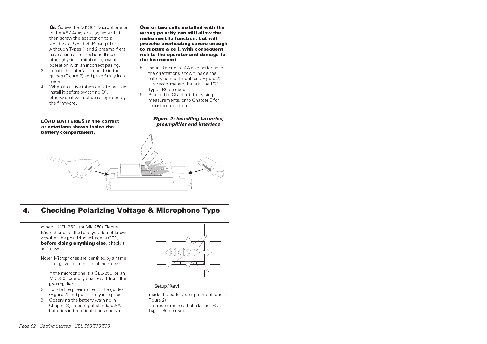
5. Insert 8 standard AA size batteries in
the orientations shown inside the
battery compartment (and Figure 2).
It is recommened that alkaline IEC
Type LR6 be used.
6. Proceed to Chapter 5 to try simple
measurements, or to Chapter 6 for
acoustic calibration.
Figure 2: Installing batteries,
preamplifier and interface
+
-
-
+
-
+
+
+
-
-
+
4. Checking Polarizing Voltage & Microphone Type
When a CEL-250* (or MK 250) Electret
Microphone is fitted and you do not know
whether the polarizing voltage is OFF,
before doing anything else
as follows.
Note*:Microphones are identified by a name
engraved on the side of the sleeve.
1. If the microphone is a CEL-250 (or an
MK 250) carefully unscrew it from the
preamplifier.
2. Locate the preamplifier in the guides
(Figure 2) and push firmly into place.
3. Observing the battery warning in
Chapter 3, insert eight standard AA
batteries in the orientations shown
Page 62 - Getting Started - CEL-553/573/593
, check it
980008e
PreviousMode
Previous
Screen
Backlight
"Series3 & 2"
NextMode
Setup/Review - ScreenOptions
inside the battery compartment (and in
Figure 2).
It is recommened that alkaline IEC
Type LR6 be used.
Select
Screen
Entries
Next
Screen
Next/
Previous
Value
Page 5
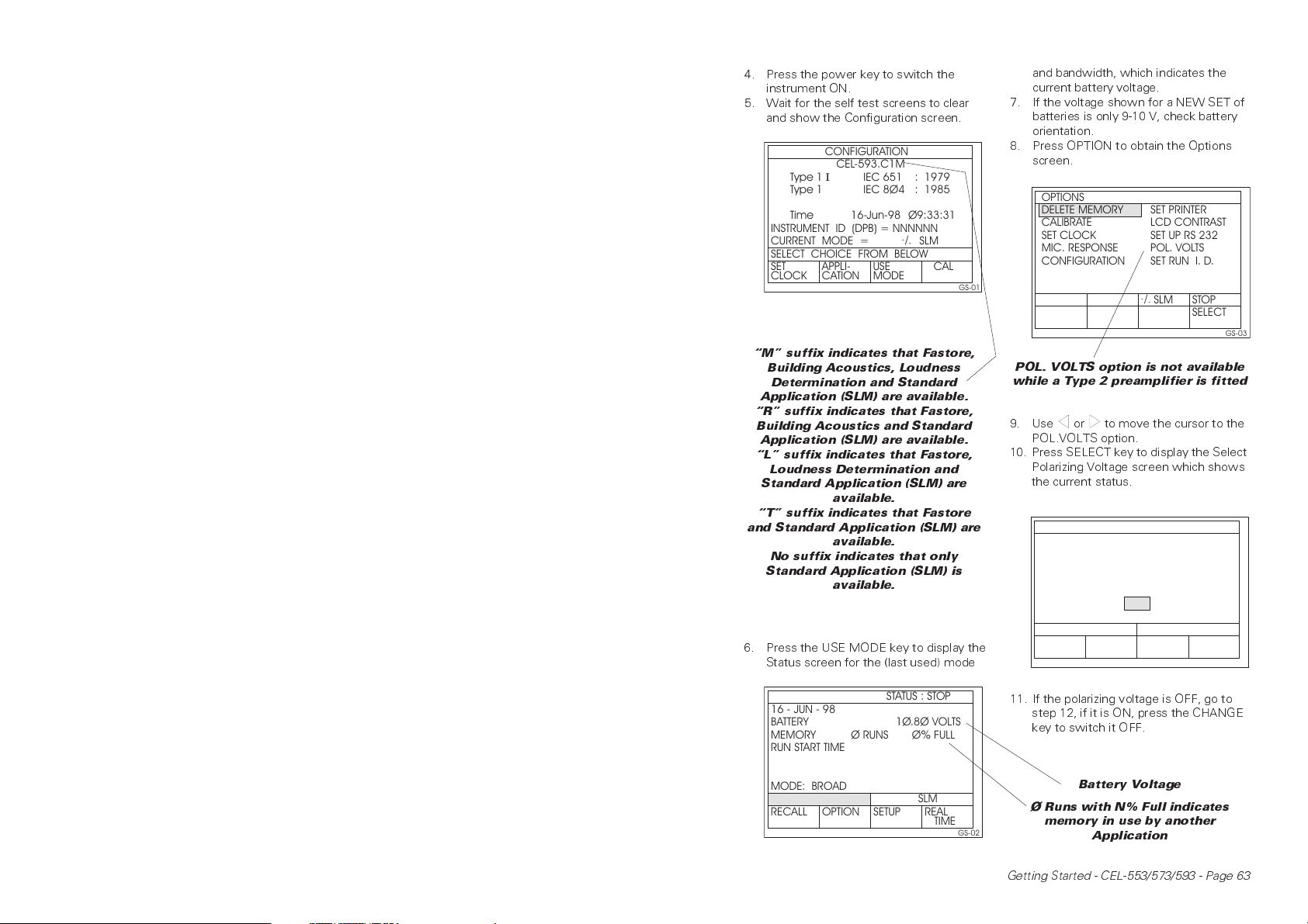
4. Press the power key to switch the
instrument ON.
5. Wait for the self test screens to clear
and show the Configuration screen.
CONFIGURATION
CEL-593.C1M
I
Type 1
Time 16-Jun-98 Ø9:33:31
INSTRUMENT ID (DPB) = NNNNNN
CURRENT MODE = SLM
SELECT CHOICE FROM BELOW
SET
CLOCK
APPLICATION
IEC 651
IEC 8Ø4Type 1
USE
MODE
:1979
:1985
-
/
-
CAL
GS-01
M suffix indicates that Fastore,
Building Acoustics, Loudness
Determination and Standard
Application (SLM) are available.
R suffix indicates that Fastore,
Building Acoustics and Standard
Application (SLM) are available.
L suffix indicates that Fastore,
Loudness Determination and
Standard Application (SLM) are
available.
T suffix indicates that Fastore
and Standard Application (SLM) are
available.
No suffix indicates that only
Standard Application (SLM) is
available.
and bandwidth, which indicates the
current battery voltage.
7. If the voltage shown for a NEW SET of
batteries is only 9-10 V, check battery
orientation.
8. Press OPTION to obtain the Options
screen.
OPTIONS
DELETE MEMORY
CALIBRATE
SET CLOCK
MIC. RESPONSE
CONFIGURATION
SET PRINTER
LCD CONTRAST
SET UP RS 232
POL. VOLTS
SET RUN I. D.
-
/
STOPSLM
-
SELECT
GS-03
POL. VOLTS option is not available
while a Type 2 preamplifier is fitted
9. Use or to move the cursor to the
POL.VOLTS option.
10. Press SELECT key to display the Select
Polarizing Voltage screen which shows
the current status.
SELECT POLARIZING VOLTAGE
200 VOLT POL. VOLTAGE FOR
AIR CONDENSER MICROPHONES
IS
ON
6. Press the USE MODE key to display the
Status screen for the (last used) mode
STATUS : STOP
16-JUN-98
BATTERY
MEMORY
RUN START TIME
RUN ELAPSE TIME
APP: SOUND ANALYSER
MODE: BROADBAND SLM
-
/
SLM
-
RECALL
OPTION SETUP REAL
Ø9 : 35 : 15
1Ø.8Ø VOLTS
Ø% FULLØRUNS
-
/
SLM
-
TIME
GS-02
CHANGE
GS-04
11. If the polarizing voltage is OFF, go to
step 12, if it is ON, press the CHANGE
key to switch it OFF.
Battery Voltage
Ø Runs with N% Full indicates
memory in use by another
Application
Getting Started - CEL-553/573/593 - Page 63
Page 6
Also use this screen to switch the
polarizing voltage ON for condenser
microphones.
12. Press power to switch the instrument
OFF before re-installing the
microphone.
Note: The FORMAT option on the last System
Test screen should be treated with
great respect !
It purges all stored data and set ups,
except for the initial set ups provided
by the factory.
5. Trying Simple Octave Band Measurements
980009e
Previous
Screen
(Same
Setup)
Backlight
"Series3 & 2"
PreviousData
StoredinThisRun
(WhenAvailable)
NextData
StoredinThisRun
(WhenAvailable)
Change
Frequency
Next
Screen
(Same
Setup)
Commands
Measurement- ScreenOptions
Observe the Warnings in Chapter 3.
With microphone type identified and
polarizing voltage checked (Chapter 4),
with batteries, preamplifier, microphone
and interface installed (Chapter 3), try
some simple measurements with a B or C
version instrument.
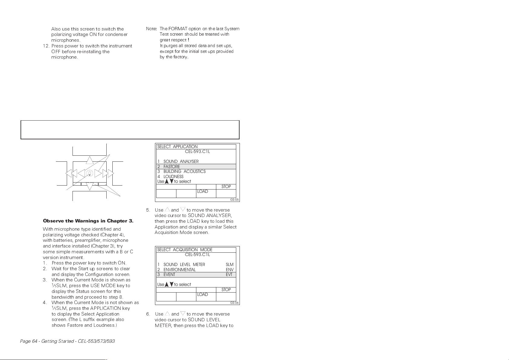
1. Press the power key to switch ON.
2. Wait for the Start up screens to clear
and display the Configuration screen.
3. When the Current Mode is shown as
1
⁄1SLM, press the USE MODE key to
display the Status screen for this
bandwidth and proceed to step 8.
4. When the Current Mode is not shown as
1
⁄1SLM, press the APPLICATION key
to display the Select Application
screen. (The L suffix example also
shows Fastore and Loudness.)
SELECT APPLICATION
1 SOUND ANALYSER
23FASTORE
BUILDING ACOUSTICS
4
LOUDNESS
Use to select
CEL-593.C1L
STOP
LOAD
5. Use and to move the reverse
video cursor to SOUND ANALYSER,
then press the LOAD key to load this
Application and display a similar Select
Acquisition Mode screen.
SELECT ACQUISITION MODE
1
SOUND LEVEL METER
2
ENVIRONMENTAL
3
EVENT
Use to select
CEL-593.C1L
STOP
LOAD
6. Use and to move the reverse
video cursor to SOUND LEVEL
METER, then press the LOAD key to
GS-05
SLM
ENV
EVT
GS-06
Page 64 - Getting Started - CEL-553/573/593
Page 7
SELECT BANDWIDTH
CEL-553.C1T
-
1BROADBAND
23OCTAVE BAND
THIRD OCTAVE BAND
/
SLM
-
1
/
SLM
1
1
/
SLM
3
Use to select
STOP
LOAD
GS-07
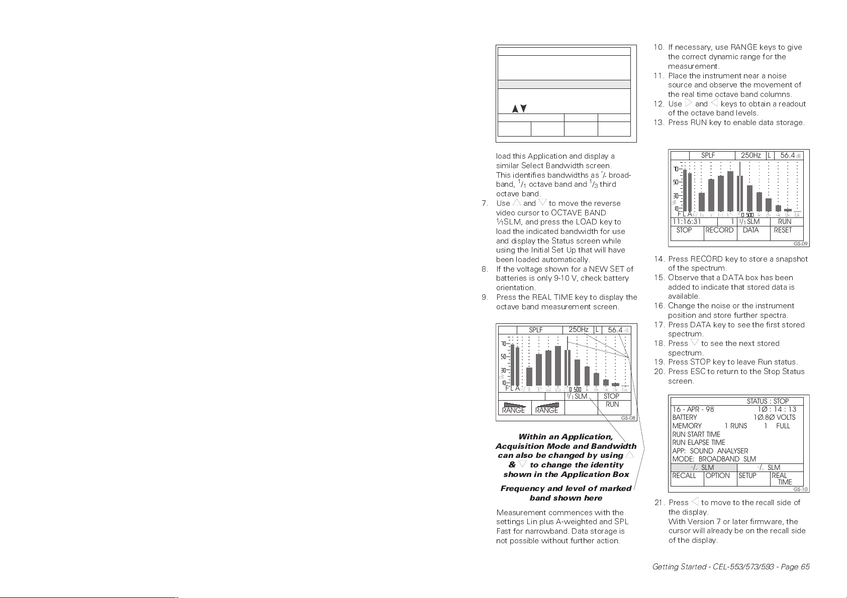
load this Application and display a
similar Select Bandwidth screen.
This identifies bandwidths as
1
/1octave band and1/3third
band,
-
/-broad-
octave band.
7. Use and to move the reverse
video cursor to OCTAVE BAND
1
⁄1SLM, and press the LOAD key to
load the indicated bandwidth for use
and display the Status screen while
using the Initial Set Up that will have
been loaded automatically.
8. If the voltage shown for a NEW SET of
batteries is only 9-10 V, check battery
orientation.
9. Press the REAL TIME key to display the
octave band measurement screen.
L
250Hz
1
/
SLM
1
56.4
STOP
RUN
GS-08
AL
F
RANGE
SPLF
RANGE
Within an Application,
Acquisition Mode and Bandwidth
can also be changed by using
& to change the identity
shown in the Application Box
Frequency and level of marked
band shown here
Measurement commences with the
settings Lin plus A-weighted and SPL
Fast for narrowband. Data storage is
not possible without further action.
10. If necessary, use RANGE keys to give
the correct dynamic range for the
measurement.
11. Place the instrument near a noise
source and observe the movement of
the real time octave band columns.
12. Use and keys to obtain a readout
of the octave band levels.
13. Press RUN key to enable data storage.
250Hz
AL
F
11:16:31
STOP
SPLF
1
RECORD
1
/
SLM
1
DATA
L
56.4
RUN
RESET
GS-09
14. Press RECORD key to store a snapshot
of the spectrum.
15. Observe that a DATA box has been
added to indicate that stored data is
available.
16. Change the noise or the instrument
position and store further spectra.
17. Press DATA key to see the first stored
spectrum.
18. Press to see the next stored
spectrum.
19. Press STOP key to leave Run status.
20. Press ESC to return to the Stop Status
screen.
STATUS : STOP
16 - APR - 98
BATTERY
MEMORY
1Ø : 14 : 13
1Ø.8Ø VOLTS
1% FULL1RUNS
RUN START TIME
RUN ELAPSE TIME
APP: SOUND ANALYSER
MODE: BROADBAND SLM
RECALL
-
/
SLM
-
OPTION SETUP REAL
-
/
SLM
-
TIME
GS-10
21. Press to move to the recall side of
the display.
With Version 7 or later firmware, the
cursor will already be on the recall side
of the display.
Getting Started - CEL-553/573/593 - Page 65
Page 8
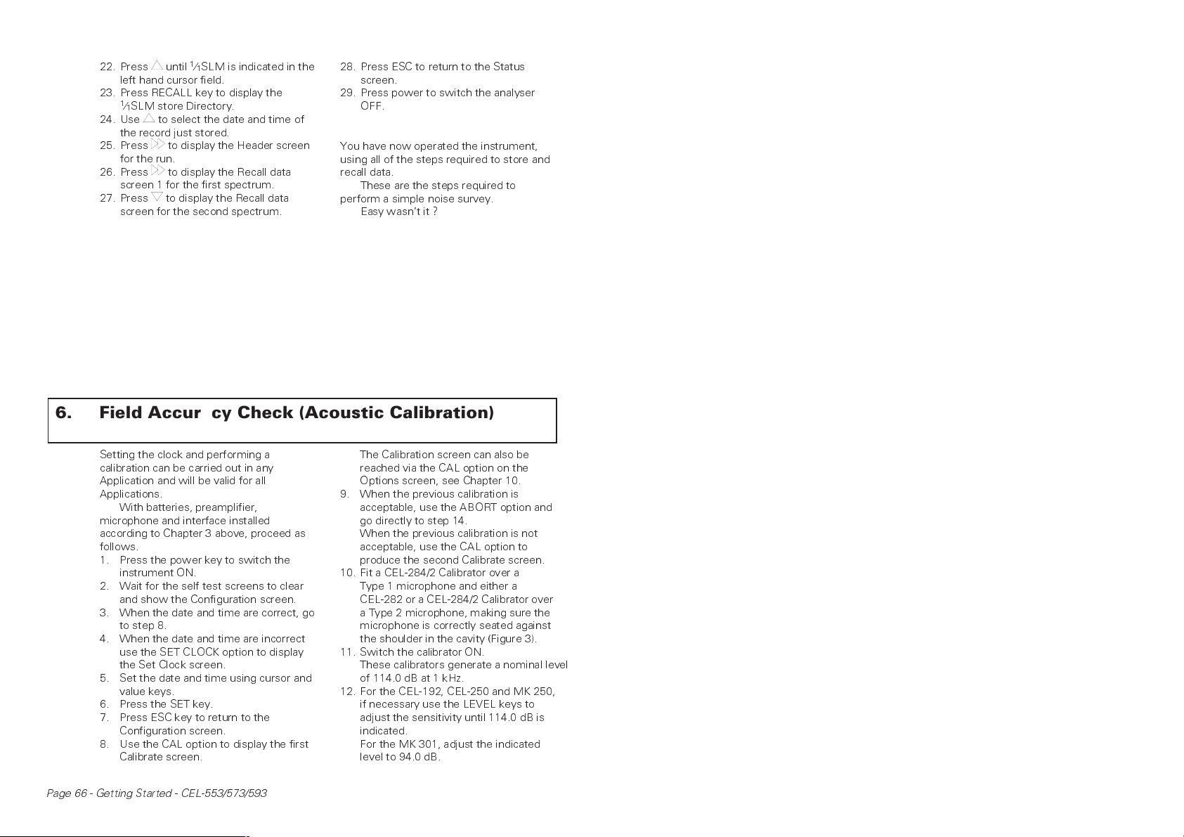
22. Press until1⁄1SLM is indicated in the
left hand cursor field.
23. Press RECALL key to display the
1
⁄1SLM store Directory.
24. Use to select the date and time of
the record just stored.
25. Press to display the Header screen
for the run.
26. Press to display the Recall data
screen 1 for the first spectrum.
27. Press to display the Recall data
screen for the second spectrum.
28. Press ESC to return to the Status
screen.
29. Press power to switch the analyser
OFF.
You have now operated the instrument,
using all of the steps required to store and
recall data.
These are the steps required to
perform a simple noise survey.
Easy wasnt it ?
6. Field Accuracy Check (Acoustic Calibration)
Setting the clock and performing a
calibration can be carried out in any
Application and will be valid for all
Applications.
With batteries, preamplifier,
microphone and interface installed
according to Chapter 3 above, proceed as
follows.
1. Press the power key to switch the
instrument ON.
2. Wait for the self test screens to clear
and show the Configuration screen.
3. When the date and time are correct, go
to step 8.
4. When the date and time are incorrect
use the SET CLOCK option to display
the Set Clock screen.
5. Set the date and time using cursor and
value keys.
6. Press the SET key.
7. Press ESC key to return to the
Configuration screen.
8. Use the CAL option to display the first
Calibrate screen.
Page 66 - Getting Started - CEL-553/573/593
The Calibration screen can also be
reached via the CAL option on the
Options screen, see Chapter 10.
9. When the previous calibration is
acceptable, use the ABORT option and
go directly to step 14.
When the previous calibration is not
acceptable, use the CAL option to
produce the second Calibrate screen.
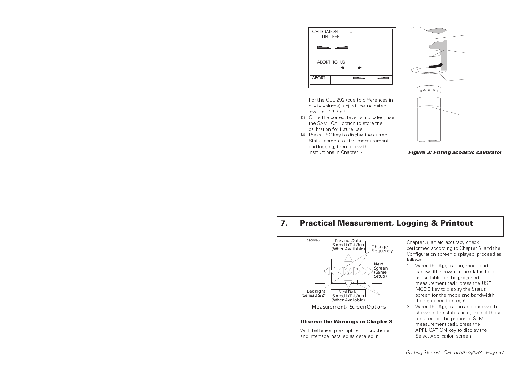
10. Fit a CEL-284/2 Calibrator over a
Type 1 microphone and either a
CEL-282 or a CEL-284/2 Calibrator over
a Type 2 microphone, making sure the
microphone is correctly seated against
the shoulder in the cavity (Figure 3).
11. Switch the calibrator ON.
These calibrators generate a nominal level
of 114.0 dB at 1 kHz.
12. For the CEL-192, CEL-250 and MK 250,
if necessary use the LEVEL keys to
adjust the sensitivity until 114.0 dB is
indicated.
For the MK 301, adjust the indicated
level to 94.0 dB.
Page 9
e
CALIBRATION
LIN LEVEL
FIT CALIBRATOR AND USE
PRESS SAVE-CAL TO SAVE AND
USE NEW SETTING OR PRESS
ABORT TO USE LAST SETTING
STANDARD CALIBRATION
ABORT
SAVE
more
CAL
DIRECTION
65.Ø dB
TO SET LEVEL
LEVEL LEVEL
GS-11
For the CEL-292 (due to differences in
cavity volume), adjust the indicated
level to 113.7 dB.
13. Once the correct level is indicated, use
the SAVE CAL option to store the
calibration for future use.
14. Press ESC key to display the current
Status screen to start measurement
and logging, then follow the
instructions in Chapter 7.
Calibrator
Shoulder
'O' Ring
Microphone &
Preamplifier
900049
Figure 3: Fitting acoustic calibrator
7. Practical Measurement, Logging & Printout
980009e
Previous
Screen
(Same
Setup)
Backlight
"Series3 & 2"
Measurement- ScreenOptions
Observe the Warnings in Chapter 3.
With batteries, preamplifier, microphone
and interface installed as detailed in
PreviousData
StoredinThisRun
(WhenAvailable)
NextData
StoredinThisRun
(WhenAvailable)
Change
Frequency
Next
Screen
(Same
Setup)
Commands
Chapter 3, a field accuracy check
performed according to Chapter 6, and the
Configuration screen displayed, proceed as
follows.
1. When the Application, mode and
bandwidth shown in the status field
are suitable for the proposed
measurement task, press the USE
MODE key to display the Status
screen for the mode and bandwidth,
then proceed to step 6.
2. When the Application and bandwidth
shown in the status field, are not those
required for the proposed SLM
measurement task, press the
APPLICATION key to display the
Select Application screen.
Getting Started - CEL-553/573/593 - Page 67
Page 10
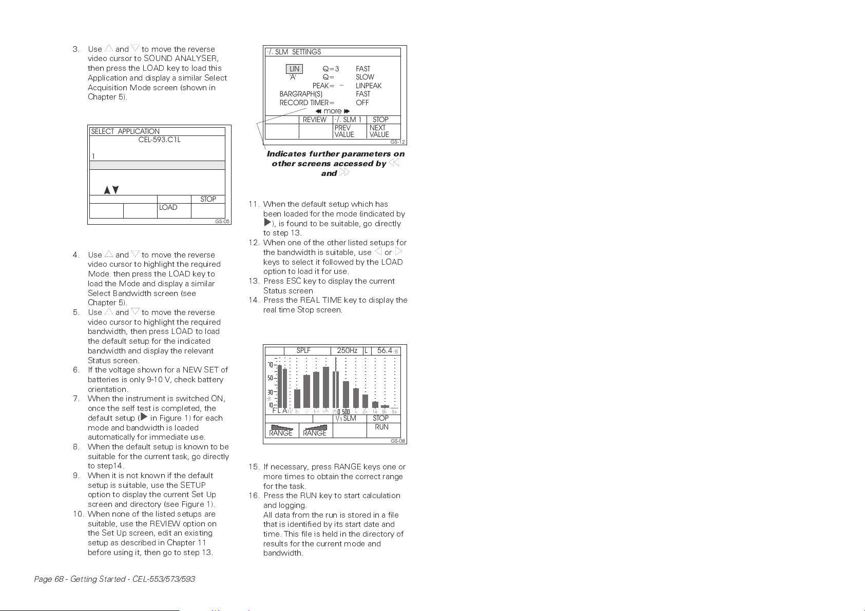
3. Use and to move the reverse
video cursor to SOUND ANALYSER,
then press the LOAD key to load this
Application and display a similar Select
Acquisition Mode screen (shown in
Chapter 5).
SELECT APPLICATION
1 SOUND ANALYSER
23FASTORE
BUILDING ACOUSTICS
4
LOUDNESS
Use to select
CEL-593.C1L
STOP
LOAD
GS-05
4. Use and to move the reverse
video cursor to highlight the required
Mode. then press the LOAD key to
load the Mode and display a similar
Select Bandwidth screen (see
Chapter 5).
5. Use and to move the reverse
video cursor to highlight the required
bandwidth, then press LOAD to load
the default setup for the indicated
bandwidth and display the relevant
Status screen.
6. If the voltage shown for a NEW SET of
batteries is only 9-10 V, check battery
orientation.
7. When the instrument is switched ON,
once the self test is completed, the
default setup ( in Figure 1) for each
mode and bandwidth is loaded
automatically for immediate use.
8. When the default setup is known to be
suitable for the current task, go directly
to step14.
9. When it is not known if the default
setup is suitable, use the SETUP
option to display the current Set Up
screen and directory (see Figure 1).
10. When none of the listed setups are
suitable, use the REVIEW option on
the Set Up screen, edit an existing
setup as described in Chapter 11
before using it, then go to step 13.
-
/
SLM SETTINGS
-
LIN
'A'
BARGRAPH(S) FAST
RECORD TIMER= OFF
Q=3
Q=
_
PEAK= LINPEAK
more
-
REVIEW
/
-
PREV
VALUE
FAST
SLOW
STOPSLM 1
NEXT
VALUE
GS-12
Indicates further parameters on
other screens accessed by
and
11. When the default setup which has
been loaded for the mode (indicated by
), is found to be suitable, go directly
to step 13.
12. When one of the other listed setups for
the bandwidth is suitable, use or
keys to select it followed by the LOAD
option to load it for use.
13. Press ESC key to display the current
Status screen
14. Press the REAL TIME key to display the
real time Stop screen.
L
250Hz
1
/
SLM
1
56.4
STOP
RUN
GS-08
AL
F
RANGE
SPLF
RANGE
15. If necessary, press RANGE keys one or
more times to obtain the correct range
for the task.
16. Press the RUN key to start calculation
and logging.
All data from the run is stored in a file
that is identified by its start date and
time. This file is held in the directory of
results for the current mode and
bandwidth.
Page 68 - Getting Started - CEL-553/573/593
Page 11
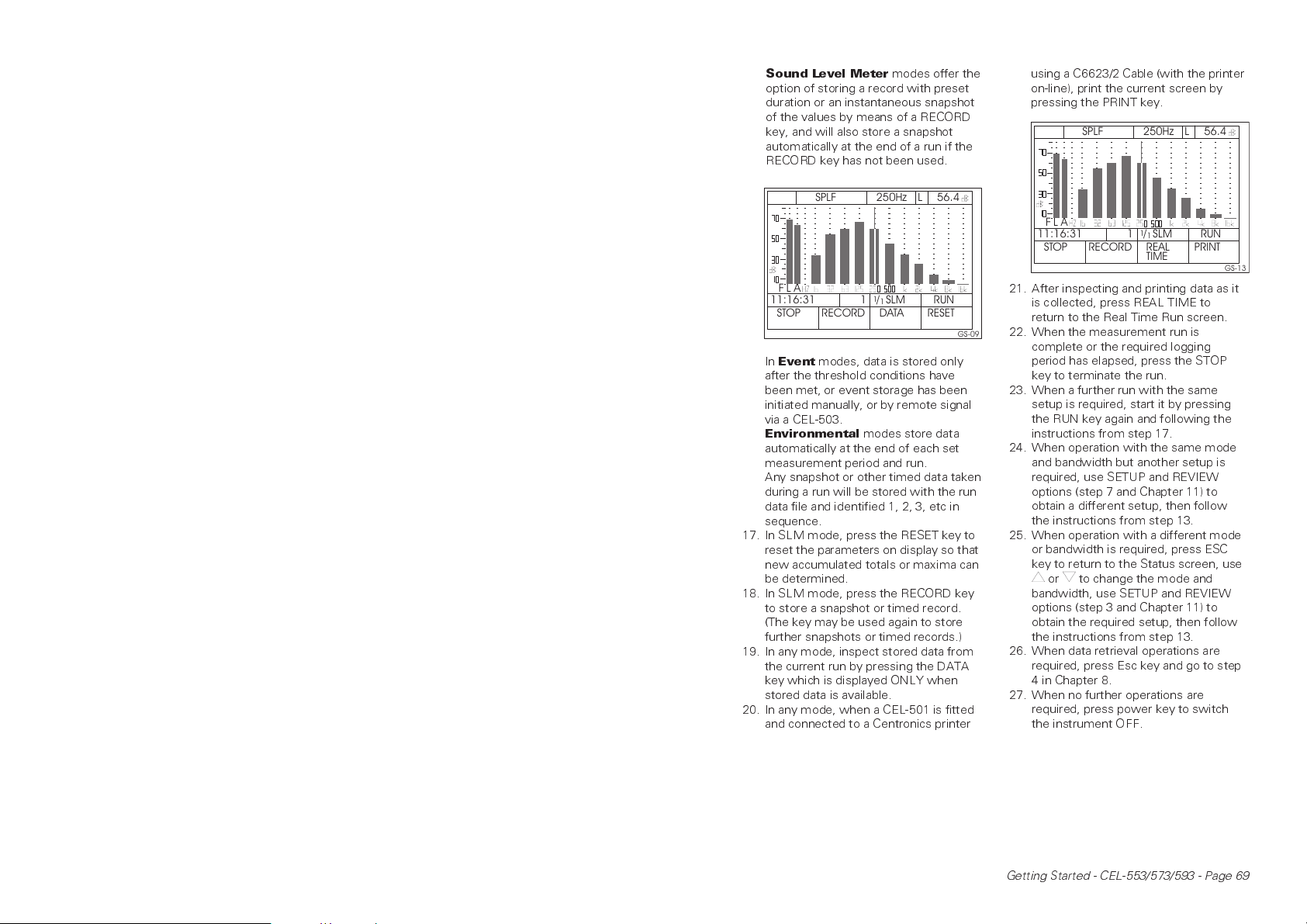
Sound Level Meter
modes offer the
option of storing a record with preset
duration or an instantaneous snapshot
of the values by means of a RECORD
key, and will also store a snapshot
automatically at the end of a run if the
RECORD key has not been used.
250Hz
F
11:16:31
STOP
In
Event
SPLF
AL
1
RECORD
modes, data is stored only
1
/
SLM
1
DATA
L
56.4
RUN
RESET
GS-09
after the threshold conditions have
been met, or event storage has been
initiated manually, or by remote signal
via a CEL-503.
Environmental
modes store data
automatically at the end of each set
measurement period and run.
Any snapshot or other timed data taken
during a run will be stored with the run
data file and identified 1, 2, 3, etc in
sequence.
17. In SLM mode, press the RESET key to
reset the parameters on display so that
new accumulated totals or maxima can
be determined.
18. In SLM mode, press the RECORD key
to store a snapshot or timed record.
(The key may be used again to store
further snapshots or timed records.)
19. In any mode, inspect stored data from
the current run by pressing the DATA
key which is displayed ONLY when
stored data is available.
20. In any mode, when a CEL-501 is fitted
and connected to a Centronics printer
using a C6623/2 Cable (with the printer
on-line), print the current screen by
pressing the PRINT key.
250Hz
AL
F
11:16:31
STOP
SPLF
1
RECORD
1
/
SLM
1
REAL
TIME
L
56.4
RUN
PRINT
GS-13
21. After inspecting and printing data as it
is collected, press REAL TIME to
return to the Real Time Run screen.
22. When the measurement run is
complete or the required logging
period has elapsed, press the STOP
key to terminate the run.
23. When a further run with the same
setup is required, start it by pressing
the RUN key again and following the
instructions from step 17.
24. When operation with the same mode
and bandwidth but another setup is
required, use SETUP and REVIEW
options (step 7 and Chapter 11) to
obtain a different setup, then follow
the instructions from step 13.
25. When operation with a different mode
or bandwidth is required, press ESC
key to return to the Status screen, use
or to change the mode and
bandwidth, use SETUP and REVIEW
options (step 3 and Chapter 11) to
obtain the required setup, then follow
the instructions from step 13.
26. When data retrieval operations are
required, press Esc key and go to step
4 in Chapter 8.
27. When no further operations are
required, press power key to switch
the instrument OFF.
Getting Started - CEL-553/573/593 - Page 69
Page 12
8. Retrieving Stored Data
980010e
Previous
Screen
(Same
Record)
Backlight
"Series3 & 2"
PreviousRecord
(SameScreen)
NextRecord
(SameScreen)
Change
Frequency
Next
Screen
(Same
Record)
Next/Previous
Run
Recall-ScreenOptions
To retrieve stored data, it is not necessary
to have the preamplifier, microphone and
interface installed.
However, when data is to be
downloaded, the relevant interface must
be attached (see Chapter 3).
1. Switch the instrument ON.
2. Wait for the self test screens to clear
and the relevant Configuration screen
to be displayed.
3. When the cursor is on the Measure
(right side) Application Box, use to
move it to the Recall (left side)
Application Box.
4. When the required data was stored
using a different Application from that
currently loaded, change the Appli-
cation as described in Chapters 5 or 7.
5. When the required data was stored
using the current Application, press
the USE MODE key to obtain the
Status screen for the (last used) mode
and bandwidth for this Application.
Version 7 and later firmware will
highlight the recall field.
6. Press or keys sufficient times to
display the required recall mode and
bandwidth in the cursor field.
7. Use the RECALL option to display the
Directory screen for the bandwidth.
8. Press or to move the cursor to the
required entry, identified by date and
time.
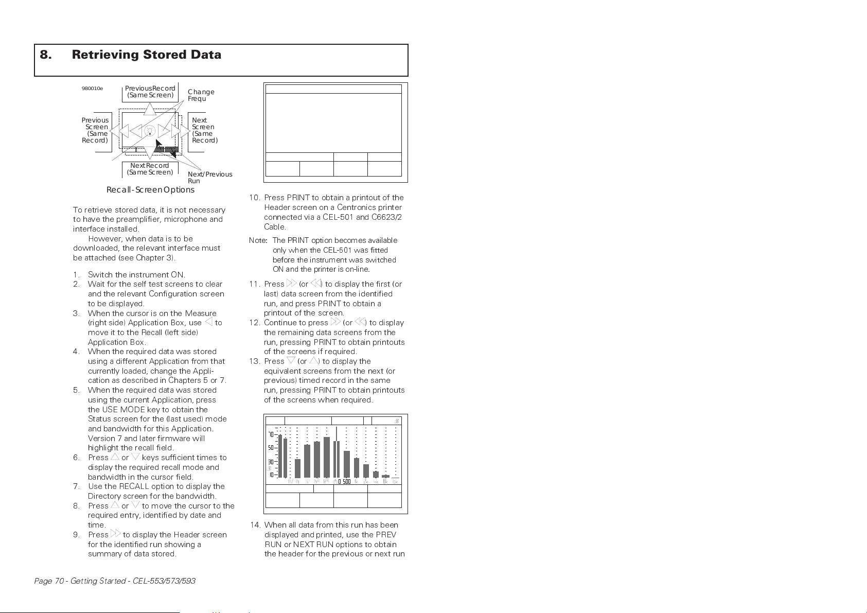
9. Press to display the Header screen
for the identified run showing a
summary of data stored.
HEADER
START
END
LENGTH
TIMED RECS
MIC=FF 2ØØV=ON TYPE=1
F, S L, A Q 3
PRINT
LAST CAL 16-APR-98
16-APR-98 1Ø:13:23
16-APR-98 1Ø:44:38
Ø DAYS Ø:31:16
4
-
/
RECALL
SLM
-
PREV NEXT
RUN RUN
GS-14
10. Press PRINT to obtain a printout of the
Header screen on a Centronics printer
connected via a CEL-501 and C6623/2
Cable.
Note: The PRINT option becomes available
only when the CEL-501 was fitted
before the instrument was switched
ON and the printer is on-line.
11. Press (or ) to display the first (or
last) data screen from the identified
run, and press PRINT to obtain a
printout of the screen.
12. Continue to press (or ) to display
the remaining data screens from the
run, pressing PRINT to obtain printouts
of the screens if required.
13. Press (or ) to display the
equivalent screens from the next (or
previous) timed record in the same
run, pressing PRINT to obtain printouts
of the screens when required.
250Hz
L
1
/
SLM
1
PREV NEXT
RUN RUN
56.4
RECALL
GS-15
F
PRINT
SPLF
AL
111:16:31
14. When all data from this run has been
displayed and printed, use the PREV
RUN or NEXT RUN options to obtain
the header for the previous or next run
Page 70 - Getting Started - CEL-553/573/593
Page 13
in this store directory, then resume
the instructions from step 8.
15. When all required data from this
directory has been displayed and
printed, press ESC key to return to the
Status screen.
16. When data from another bandwidth is
to be displayed, use or keys
sufficient times to display the required
store directory and follow the
instructions from step 8.
17. When further measurement and
logging are required, refer to Chapter 7.
18. When no further operations are
required, press power to switch the
instrument OFF.
9. Performing Full Data Download
A full download of all data stored in the
instrument is possible only when a
CEL-502 RS232 Interface is fitted to the
instrument and connected via C6621/2 or
C6622/2 Cables to a PC running application
software.
The following Windows programs are
available for Series 3.
dB1 (CEL-6694) Download and Control
Software for ALL Applications, including
Loudness. This program has no graphing
capabilites but can export data to other
standard software packages for graphing
and printing if required.
dB2 (CEL-6695) Software for Sound
Analyser Application with comprehensive
graphing and data manipulation fqcilities.
dB3 (CEL-6696) Software for Fastore
Application with comprehensive graphing
and data manipulation fqcilities.
dB4 (CEL-6697) Software for Building
Acoustics Application with comprehensive
graphing and data manipulation fqcilities.
Downloading takes place under the
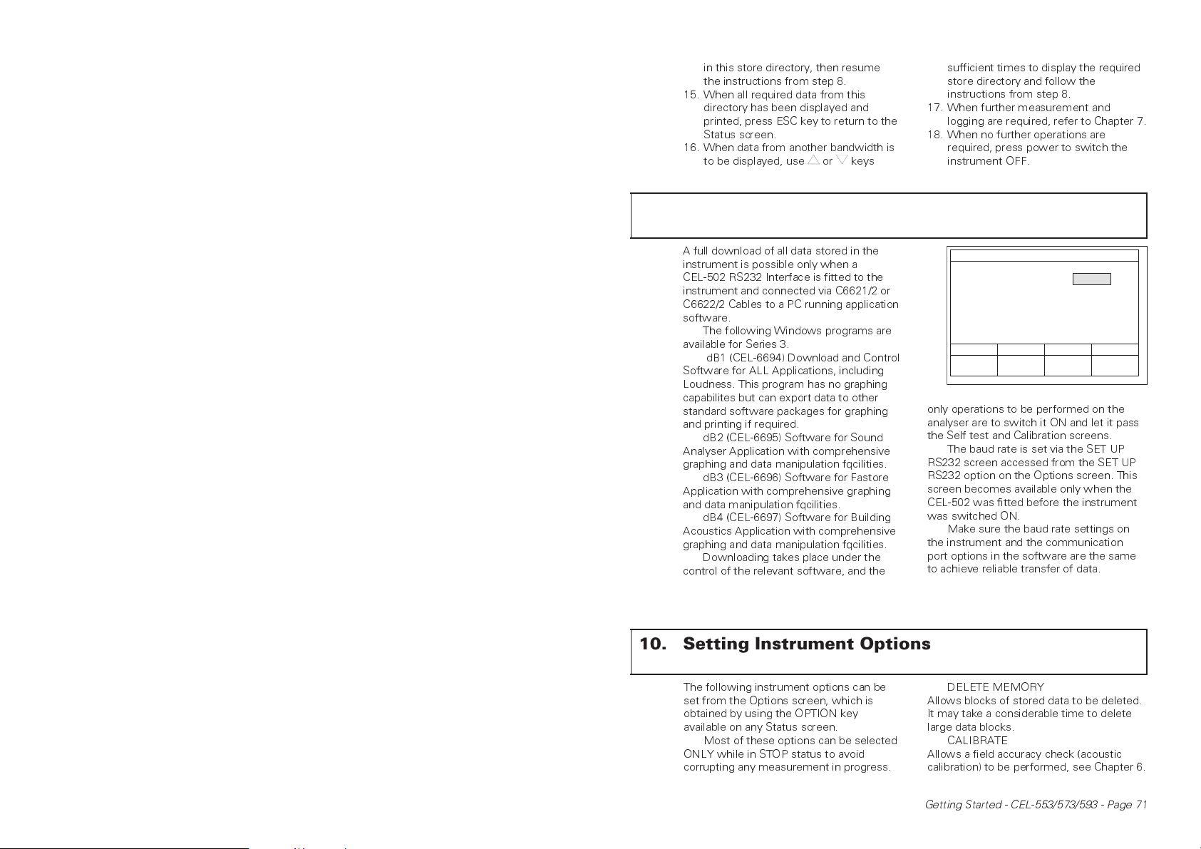
control of the relevant software, and the
10. Setting Instrument Options
SETUP RS 232
BAUD RATE 192ØØ
PREV
VALUE
only operations to be performed on the
analyser are to switch it ON and let it pass
the Self test and Calibration screens.
The baud rate is set via the SET UP
RS232 screen accessed from the SET UP
RS232 option on the Options screen. This
screen becomes available only when the
CEL-502 was fitted before the instrument
was switched ON.
Make sure the baud rate settings on
the instrument and the communication
port options in the software are the same
to achieve reliable transfer of data.
NEXT
VALUE
GS-16
The following instrument options can be
set from the Options screen, which is
obtained by using the OPTION key
available on any Status screen.
Most of these options can be selected
ONLY while in STOP status to avoid
corrupting any measurement in progress.
DELETE MEMORY
Allows blocks of stored data to be deleted.
It may take a considerable time to delete
large data blocks.
CALIBRATE
Allows a field accuracy check (acoustic
calibration) to be performed, see Chapter 6.
Getting Started - CEL-553/573/593 - Page 71
Page 14
SET CLOCK
Allows time and date to be set.
MIC. RESPONSE
Allows microphone response to be
changed between free field to meet IEC
standards and random incidence that
meets ANSI standards.
CONFIGURATION
Displays the instrument configuration.
LCD CONTRAST
Allows the display contrast to be changed.
SET PRINTER
Allows the printer output format to be
specified as Epson dot matrix or Laserjet
compatible so data displayed on the
screen can be printed via a CEL-501
Parallel (Centronics) Interface (Chapter 8).
SETUP RS232
Allows the RS232 baud rate to be speci-
fied so that stored data can be transferred
over a CEL-502 RS232 Interface.
11. Editing Stored Set Ups
OPTIONS
DELETE MEMORY
CALIBRATE
SET CLOCK
MIC. RESPONSE
CONFIGURATION
SET PRINTER
LCD CONTRAST
SET UP RS 232
POL. VOLTS
SET RUN I. D.
-
/
STOPSLM
-
SELECT
GS-03
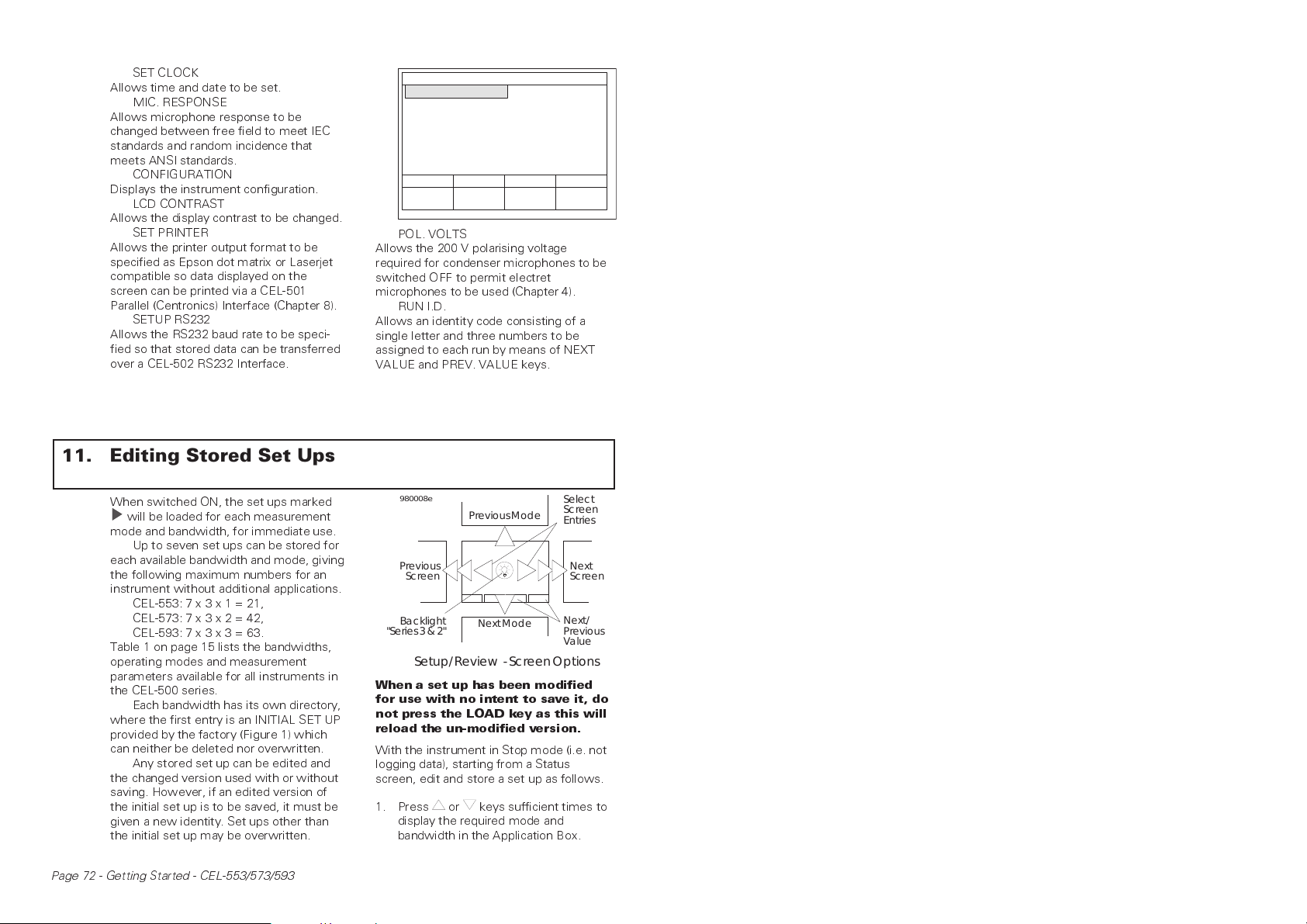
POL. VOLTS
Allows the 200 V polarising voltage
required for condenser microphones to be
switched OFF to permit electret
microphones to be used (Chapter 4).
RUN I.D.
Allows an identity code consisting of a
single letter and three numbers to be
assigned to each run by means of NEXT
VALUE and PREV. VALUE keys.
When switched ON, the set ups marked
will be loaded for each measurement
mode and bandwidth, for immediate use.
Up to seven set ups can be stored for
each available bandwidth and mode, giving
the following maximum numbers for an
instrument without additional applications.
CEL-553: 7 x 3 x 1 = 21,
CEL-573: 7 x 3 x 2 = 42,
CEL-593: 7 x 3 x 3 = 63.
Table 1 on page 15 lists the bandwidths,
operating modes and measurement
parameters available for all instruments in
the CEL-500 series.
Each bandwidth has its own directory,
where the first entry is an INITIAL SET UP
provided by the factory (Figure 1) which
can neither be deleted nor overwritten.
Any stored set up can be edited and
the changed version used with or without
saving. However, if an edited version of
the initial set up is to be saved, it must be
given a new identity. Set ups other than
the initial set up may be overwritten.
Page 72 - Getting Started - CEL-553/573/593
980008e
Previous
Screen
Backlight
"Series3 & 2"
PreviousMode
NextMode
Select
Screen
Entries
Next
Screen
Next/
Previous
Value
Setup/Review - ScreenOptions
When a set up has been modified
for use with no intent to save it, do
not press the LOAD key as this will
reload the un-modified version.
With the instrument in Stop mode (i.e. not
logging data), starting from a Status
screen, edit and store a set up as follows.
1. Press or keys sufficient times to
display the required mode and
bandwidth in the Application Box.
Page 15
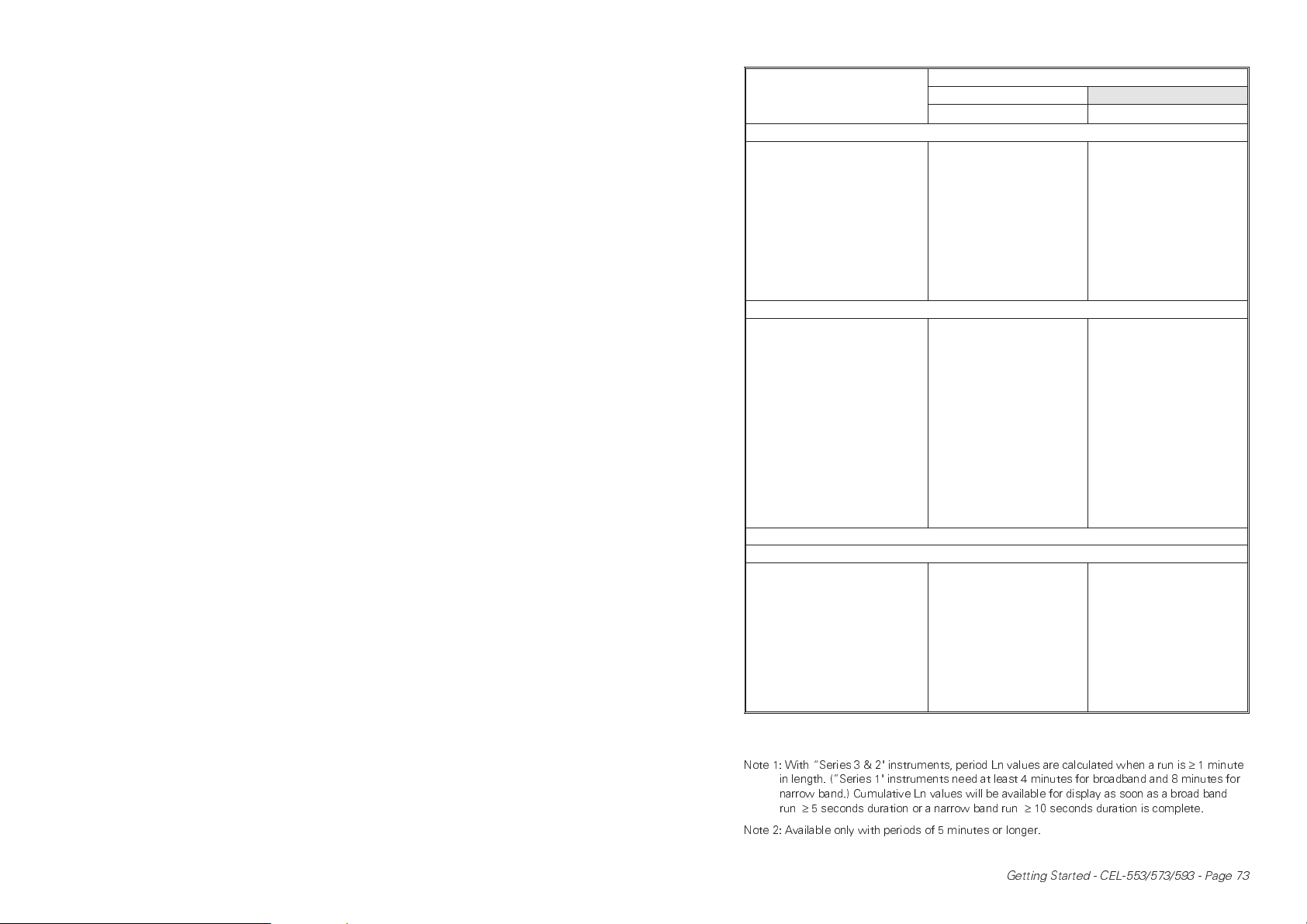
Table 1: Bandwidths
Operating Modes &
Measurement Parameters
CEL-5X3.C1/C2 (
CEL-5X3.A1/A2 (
Broad Band Octave & Third Octave
−
−
⁄
)
−
Real Time Sound Level Meter
Freq Weightings
Time Weightings
Exch Rate Q
Parameters
2 (from Lin, A & C)
2 (from Slow, Fast & Impulse)
2 (from Q=3, 4, 5 & 6)
SPL
Max & Min
& IL
L
eq
avg
(with Q=3)
epd
Tm3<m5
eq
L
LinPeak/C Peak
L
TWA (with Q=5 & Slow wtg)
SEL
L
Environmental Mode (Not CEL-553)
Freq Weightings
Time Weightings
Exch Rate Q
Parameters
Meas Period
Durations
Auto Start/Stop Times
Ln values
Profiles
1
2 (from Lin, A & C)
1 (from Slow, Fast & Impulse)
1 (from Q=3, 4, 5 & 6)
SPL not stored
Max & Min
SEL of period
& IL
L
eq
avg
Tm3<m5
eq
2
or 1 sec L
eq
L
LinPeak/C Peak
L
0.5, 1, 5, 10, 15, 30 sec
1, 5, 10, 15, 20, 30, 60 min
24 sets
5
1 SecMax
A cumulative result set and set of histograms are ALWAYS stored
Event Mode (CEL-593 Only)
Freq Weightings
Time Weightings
Exch Rate Q
Parameters
Profiles
Triggering
Threshold
Triggering Delays
1 (from Lin, A & C)
1 (from Slow, Fast & Impulse)
Fixed at Q=3
Max Level
Time of Max
SEL
Duration
Event L
eq
LinPeak/C Peak
1 SecMax
Manual or Threshold + Delay
40 to 139 dB
1 to 30 sec
1
1
⁄
⁄
⁄
) B1/B2 (
−
1
3
1 x Broad &
Narrow Band
1 x Optional Broad Band
(from Lin, A & C)
1 (from Slow, Fast & Impulse)
Fixed at Q=3
SPL
Max
L
eq
1 x Broad &
Narrow Band
1 x Optional
Broad Band (from Lin, A & C)
1 (from Slow, Fast & Impulse)
Fixed at Q=3
SPL not stored
Max
L
eq
0.5, 1, 5, 10, 15, 30 sec
1, 5, 10, 15, 20, 30, 60 min
24 sets
5
1 (from Lin, A & C)
1 (from Slow, Fast & Impulse)
Fixed at Q=3
Max Level
Time of Max
SEL
Duration
Event L
eq
LinPeak/C Peak
1 SecMax
Spectrum Profiles
Manual or Threshold + Delay
40 to 139 dB
1 to 30 sec
1
−
⁄
⁄
−
1
)
Note 1: With Series 3 & 2" instruments, period Ln values are calculated when a run is≥1 minute
in length. (Series 1" instruments need at least 4 minutes for broadband and 8 minutes for
narrow band.) Cumulative Ln values will be available for display as soon as a broad band
run≥5 seconds duration or a narrow band run≥10 seconds duration is complete.
Note 2: Available only with periods of 5 minutes or longer.
Getting Started - CEL-553/573/593 - Page 73
Page 16
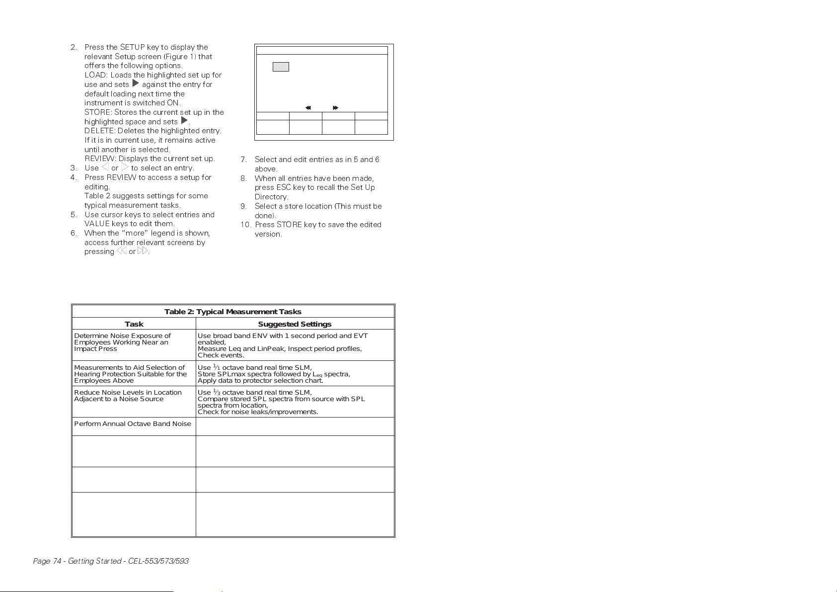
2. Press the SETUP key to display the
relevant Setup screen (Figure 1) that
offers the following options.
LOAD: Loads the highlighted set up for
use and sets against the entry for
default loading next time the
instrument is switched ON.
STORE: Stores the current set up in the
highlighted space and sets .
DELETE: Deletes the highlighted entry.
If it is in current use, it remains active
until another is selected.
REVIEW: Displays the current set up.
3. Use or to select an entry.
4. Press REVIEW to access a setup for
editing.
Table 2 suggests settings for some
typical measurement tasks.
5. Use cursor keys to select entries and
VALUE keys to edit them.
6. When the more legend is shown,
access further relevant screens by
pressing or .
Table 2: Typical Measurement Tasks
Task Suggested Settings
Determine Noise Exposure of
Employees Working Near an
Impact Press
Measurements to Aid Selection of
Hearing Protection Suitable for the
Employees Above
Reduce Noise Levels in Location
Adjacent to a Noise Source
Perform Annual Octave Band Noise
Survey in Factory at 102 Locations
Investigate Intermittent Industrial
Noise Disturbing a Quiet Neighbourhood
Police Cumulative Noise Limits Set
for a Quarry
Determine the Effect of Running
New Trains Through Quiet Countryside
Use broad band ENV with 1 second period and EVT
enabled,
Measure Leq and LinPeak, Inspect period profiles,
Check events.
Use
Store SPLmax spectra followed by L
Apply data to protector selection chart.
Use
Compare stored SPL spectra from source with SPL
spectra from location,
Check for noise leaks/improvements.
Use
Store L
Use
enabled,
Measure L
background noise, Check for events.
Use broad band ENV with 60 minute period,
Measure L
L
95
Use
enabled,
Measure L
as L
Check event frequency profiles,
Use data to find projected daily L
1
/
SLM
3
LIN FAST
(2nd BARGRAPH ONLY)
'A'
RECORD TIMER OFF
REVIEW
Q=3
=
more
1
/
3
PREV
VALUE
SETTINGS
7. Select and edit entries as in 5 and 6
above.
8. When all entries have been made,
press ESC key to recall the Set Up
Directory.
9. Select a store location (This must be
done).
10. Press STORE key to save the edited
version.
1
⁄
octave band real time SLM,
1
1
⁄
octave band real time SLM,
3
1
⁄
octave band real time SLM,
1
spectra snapshots at each location.
eq
1
⁄
octave band ENV with 10 minute period and EVT
3
and determine Ln spectra values such as L
eq
, SPLmax and determine Ln values such as
eq
background noise.
1
⁄
octave band ENV with 10 minute period and EVT
3
, SEL and determine Ln spectra values such
eq
background noise,
95
spectra,
eq
from train frequency.
eq
STOPSLM 1
NEXT
VALUE
GS-17
95
Page 74 - Getting Started - CEL-553/573/593
 Loading...