

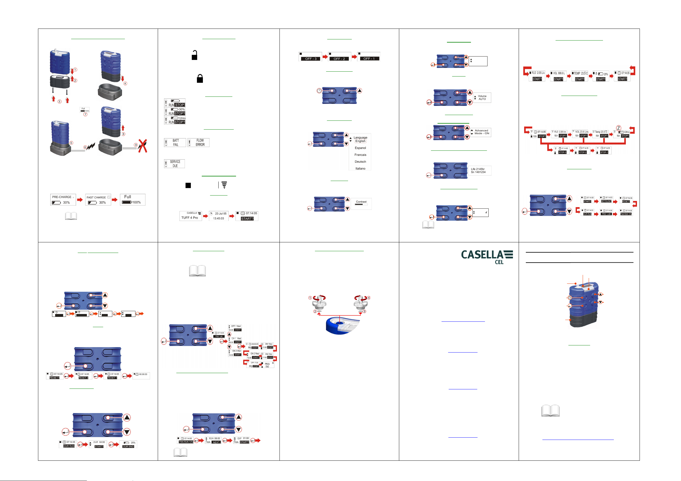
CHARGING THE TUFF / BATTERIES KEY LOCKED MODES
y
• Insert pump into charging cradle as shown above.
• Fast charge starts and the red LED on the pump flashes.
• When fully charged the blue LED will illuminate. The pump can be
• Individual battery packs can also be charged / stored in the cradle.
Attach the pump to the external calibration equipment as detailed in the
Operator’s Manual (Chapter 6.)
From menu press UP/DOWN to go to SET FLOW. Press ENTER to access Set
Flow options. Use UP/DOWN keys to adjust the flow setting required. Press
ENTER to continue. Cal Flow will be displayed. Use the UP/DOWN keys to adjust
the flow indicated on external calibration device until required value is reached.
Press Enter when flow indicated is equal to your required flow rate.
STA RT ?
(Used to reset all the previous run details from display).
Press and hold ENTER. Release ENTER when counter is at zero.
Note: If the counter is already at zero, the Reset option is not displayed.
Press ENTER to access Run Duration setup screen.
Use the UP/DOWN keys to set run duration in hours and minutes.
Press ENTER again to start the pump. The duration will be counted down as a
percentage of duration time remaining. The pump will stop when the duration end
time is reached.
Fit Battery and Connect Charger
left in the cradle on trickle charge or may be removed.
The battery pack’s own red LED will indicate that charging is in
progress.
Chapter 2 for more charging
options.
07:14:05
RESET
FLO 2.05 L/m
O.K
CAL FLOW
O.K
FLOW (CALIBRATE FLOW)
07:14:05
SET F LOW?
RUN DURATION PRO and PLUS ONLY
The keys can be set in a Partial Lock Mode or a fully Locked Mode.
PARTIAL LOCK MODE
This can be activated in Stop Mode and Run Mode. Press the On/Off key three
times within 3 seconds to enter Partial Lock Mode. In this mode the pump can only
be started and stopped.
This can only be activated in Run Mode. Press the On/Off key three times within 3
seconds to enter Locked Mode. In this mode all keys are disabled.
The symbol in the top left hand corner of the screen displays the pump mode.
Note: To Set Language go to Configuration.
If language is set, press the On/Off Key. The Firmware will run through the
initialisation screens.
LOCKED MODE
BATTERY GAUGE
Standard models – Battery gauge shows approximate
estimate of available battery capacity.
TUFF Plus Model- Here the battery status bar indicates
approximate % remaining.
PRO only - This screen shows the estimated life
remaining based on the current battery loading.
ERROR MESSAGES
STOP / RUN SYMBOLS
Stop Symbol
POWER ON
The pump stops and an error condition is
indicated by a flashing ‘!’ and red LED.
Low Battery and Flow Blockage are
shown here. After 1 minute stoppage the
pump will try to restart. All error
messages are displayed for 4 hours
before the pump turns off.
This symbol is displayed if the Run Time
exceeds 2500hrs or number of battery
charge cycles exceeds 600.
Run Symbol
(Note: The Advanced Mode must be set to ON via the configuration menu to
enable this feature.)The program is configured on a PC and then uploaded to the
Pump.
Note: If the pump is programmed to start sampling at 08:00 on Monday and the
pump is not switched ON until 08:10 on Monday it will not run until the next
Monday at 08:00.
This example assumes the intention is to run the pump for 4 hours, then pause for
1 hour, and then resume running for another 4 hours. Use the UP/DOWN keys to
step through the Stop Mode Menu Options until PRG1 screen is displayed.
Press ENTER to continue to the ‘ON 1’ screen. Use the UP/DOWN keys to review
the program set parameters.
ON1 is 08:00. OFF1 is 12:00. START2 is 13:00. PROGRAM END is 17:00.
Use the UP/DOWN keys to step through the Menu Options until the TWA screen is
displayed.
Press ENTER to continue to the TWA Run screen. Use the UP/DOWN keys to set
the total sampling duration, e.g 8 hours.
Press ENTER to continue to the Exposure time setting. Use the UP/DOWN keys to
set the Exposure Time, e.g 1 hour.
The settings entered will provide 1 hours exposure time evenly spaced over the 8
hours running time.
Press ENTER to Start.
PROGRAM OPTIONS
TIME W EIGHTE D AVERAG E (TW A)
Chapter 4 for comprehensive operating details.
(PRO ONLY)
Chapter 4 for further
programming details.
(PRO and Plus ONLY)
Press and hold the On / Off Key. A “countdown” will be displayed and the pump
will switch off.
Immediately after powering up, press and hold the UP arrow. This allows access
to the configuration screens. After approximately 8 seconds the Set Language
screen is displayed.
Use UP/DOWN keys to select the required language, then press ENTER.
Use UP/DOWN keys to adjust the contrast, then press ENTER.
POWERING OFF
CONFIGURATION
SET LANGUAGE
CONTRAST
RENEWiING THE INLET FILTER
Note: The filter element should be replaced every 3 months. The pump running
time and the operating environment can reduce this time considerably.
1. Remove the Inlet Nozzle.
2. Discard the Filter Element.
3. Fit a new Filter Element.
4. Fit and hand tighten the Inlet Nozzle.
Use UP/DOWN keys to select the required unit for displaying the ambient air
temperature (
TUFF PLUS AND PRO ONLY - Use UP/DOWN keys to select the preferred units
to display the sampled volume (i.e. always cubic metres (m
automatically from Litres to m
TUFF PRO ONLY - Use UP/DOWN keys to set the Advanced Mode ON or OFF
then press ENTER. (See
The ‘Life’ shown is the accumulated run time in hours. The Serial number is the
unique number assigned the pump. Press ENTER to continue.
This allows the user to alter or check the default calibration of the pump. This
facility is not available on the Tuff Standard unit. Please do not enter this menu
option unless you intend to alter the basic calibration of the unit.
◦
C or ◦F) then press ENTER.
TEMPERATURE
TEMP
O
De g C
VOLUME
3
), then press ENTER.
ADVANCED MODE
PROGRAM OPTIONS).
SERVICE LIFE AND SERIAL NUMBER
DEFAULT CALIBRATION
Calibrate
No
3
) or AUTO to change
For more details on calibration /
configuration options. Chapter 5.
Casella CEL
Regent House, Wolseley Road,
MK42 7JY, United Kingdom.
Phone: +44 (0) 1234 844 100
Fax: +44 (0) 1234 841 490
E-mail:
www.casellameasurement.com
Web:
17 Old Nashua Road #15
Amherst, NH 03031, USA
Toll Free: +1 800 366 2966
E-mail: info@casellausa.com
Web:
28230 Las Rozas - Madrid
Phone: + 34 91 640 75 19
E-mail: online@casella-es.com
Web:
Kempston, Bedford.
info@casellameasurement. com
Casella USA
Fax: +1 603 672 8053
www.casellausa.com
Casella Spain
Polígono Európolis
Calle C, nº4B
Spain
Fax: + 34 91 636 01 96
www.casella-es.com
Casella China
c/o IDEAL INDUSTRIES China
Unit 911, Tower W1, Oriental Plaza,
No1 East Chang An Ave
Dong Cheng District
Beijing 100738
China
Phone: +86 10 85183141
Fax: + 86 10 85183143
E-mail: info@casellameasurement.cn
www.casellachina.cn
Web:
TUFF Field Guide SM08013
MAIN MENU / STARTING A RUN
When on the Tuff pump will scroll through the Main Menu Options. The information
displayed on the screens will be the saved data from the last time the pump was
used. Press the ENTER key on any screen to start the pump. (Volume and Flow
not displayed on Standard Model.)
When the pump is running it will scroll through the Run Mode Menu options and
the blue led will be flashing. Current run data will be displayed. To stop the pump,
press and hold the ENTER key on any screen until the countdown is complete.
Note: PRO Model,(Screen Z) is the remaining run time available based on the
current flow and pressure loading. The ‘Plus’ model displays the % of remaining
battery capacity only. Standard model only displays battery status bar and elapsed
run time only. No flow rate or sampled volume are displayed.
Use the UP/DOWN keys to step through the Menu Options. Press ENTER to
access a Menu Option when it is displayed. Menu option not available in partial
lock mode.(Note: screens shown below may vary depending upon model).
HB3344-01 FIELD GUIDE FOR TUFFTM
On / Off, Cancel Key
Star t / Stop / Ent er Key
This field guide is to familiar ise you with the TUFF Personal Air Sam pling Pump range and
get you ‘up and running’ quickly. It is as sumed this is the first time you ha ve used the
instrument. (It covers all three variants , TUFF Standard, Plus and Pro.)
Please make sure the TUFF
damaged and the Inlet Nozzle is not obs tructed before attempting to use this ins trument.
We want you to get the best performance f rom the equipment and recommend you refer to
the Operator’s Manual for detailed inf ormation.
Notes:
1.
RUN MODE MAIN MENU
Inlet No zzle
Batter y
Casella Cel - TUFF
TM
and associated equipment supplied b y Casella CEL are not
MENU OPTIONS
Screen Displa
INTRODUCTION
I/R Port, Run / Alarm LEDs
Up Key
Down Key
TM
Series
Refer to the Operator’s Manual when the “boo k” symbol is displayed.
2. Multi- language field guides and full handbook s can be downloaded from:
http://www.casellameasurement.com/tuff/downloads .htm
 Loading...