

THERMOHYGROGRAPH standard
User Manual
THERMOHYGROGRAPH
standard
User Manual
COPYRIGHT
June 2000
HB 3083-02
The copyright in this document, which contains proprietary information, is
vested in CASELLA CEL. The contents of this document must not be used
for purposes other than that for which it has been supplied or reproduced or
disclosed wholly or in part without the prior written permission of
CASELLA CEL
CASELLA CEL
Regent House
Wolseley Road
Kempston
Bedford
MK42 7JY
Phone: +44 (0) 1234 844 100
Fax: +44 (0) 1234 841 490
E-mail info@casellagroup.com
Web: www.casellagroup.com
CASELLA USA
17 Old Nashua Road #15
Amherst
NH 03031
U.S.A.
Toll Free: +1 800 366 2966
Fax: +1 603 672 8053
e-mail: info@casellausa.com
Web: www.casellausa.com

Contents
THERMOHYGROGRAPH standard
User Manual
TABLE OF CONTENTS
CONTENTS ................PAGE
1. INTRODUCTION . . . . . . . . . . . . . . . . . . . . . . . . . . . 3
2. PRINCIPLE OF OPERATION . . . . . . . . . . . . . . . . . . . . 4
2.1 Humiditity Measurement . . . . . . . . . . . . . . . . . 4
2.2 Temperature Measurement . . . . . . . . . . . . . . . . 4
2.3 General...........................4
3. PREPARATION FOR USE . . . . . . . . . . . . . . . . . . . . . . 5
3.1 Removing/Replacing the Drum . . . . . . . . . . . . . . 5
3.2 Fitting/Replacing the Battery. . . . . . . . . . . . . . . . 5
3.3 Setting the Clock speed. . . . . . . . . . . . . . . . . . . 5
3.4 Fitting/Replacing the Chart. . . . . . . . . . . . . . . . . 6
3.5 Fitting/Replacing the Pens. . . . . . . . . . . . . . . . . . 6
4. OPERATING THE INSTRUMENT . . . . . . . . . . . . . . . . . . 8
5. MAINTENANCE & SPARES . . . . . . . . . . . . . . . . . . . . . 9
5.1 Routine Care . . . . . . . . . . . . . . . . . . . . . . . . 9
5.2 Quarz Clock . . . . . . . . . . . . . . . . . . . . . . . . 9
5.3 Cleaning . . . . . . . . . . . . . . . . . . . . . . . . . . 9
5.4 Service . . . . . . . . . . . . . . . . . . . . . . . . . . . 9
5.5 Spare Parts. . . . . . . . . . . . . . . . . . . . . . . . 10
6. SPECIFICATION . . . . . . . . . . . . . . . . . . . . . . . . . . 11
Page 2 of 12
THERMOHYGROGRAPH standard
User Manual
Introduction
1. INTRODUCTION
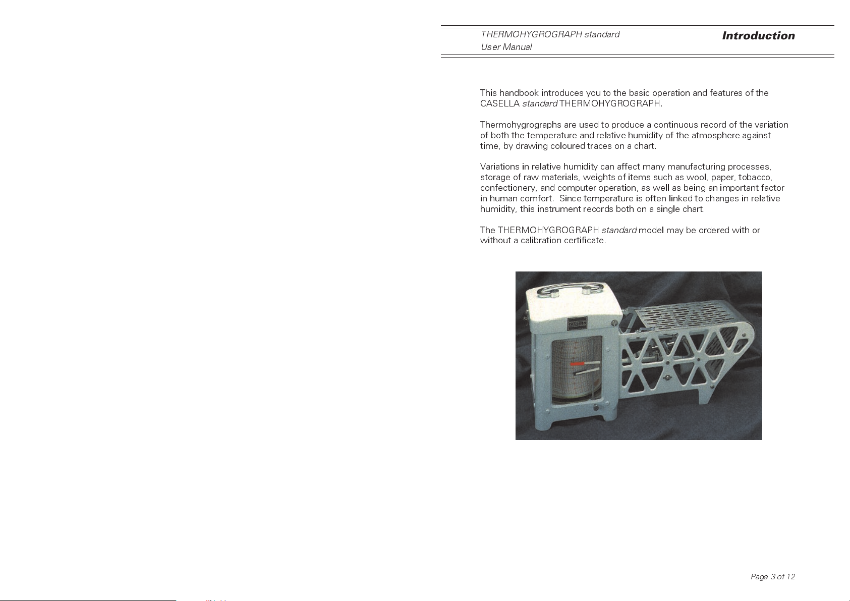
This handbook introduces you to the basic operation and features of the
CASELLA
Thermohygrographs are used to produce a continuous record of the variation
of both the temperature and relative humidity of the atmosphere against
time, by drawing coloured traces on a chart.
Variations in relative humidity can affect many manufacturing processes,
storage of raw materials, weights of items such as wool, paper, tobacco,
confectionery, and computer operation, as well as being an important factor
in human comfort. Since temperature is often linked to changes in relative
humidity, this instrument records both on a single chart.
standard
THERMOHYGROGRAPH.
The THERMOHYGROGRAPH
without a calibration certificate.
standard
model may be ordered with or
Page 3 of 12
Principle
THERMOHYGROGRAPH standard
User Manual
2 PRINCIPLE OF OPERATION
2.1 Humidity Measurement
The element that senses relative humidity is made from several strands of
specially treated human hair, which shorten as relative humidity decreases
and lengthen as it increases. The relative humidity element is connected
through a linkage to the pen arm so that changes are recorded as an ink line
on the chart. The linkage is designed to give a near linear movement over
most of the chart range.
2.2 Temperature Measurement
The temperature element is a bi-metalic strip, whose curvature depends on
the current air temperature. As the temperature changes, the angular
position of the free end of the strip changes. The free end is connected via a
linkage to the pen arm so that changes are recorded on the chart.
2.3 General
Relative humidity and temperature are recorded on the same chart, so to
distinguish between the two traces, the temperature pen is black while the
relative humidity pen is red.
To allow the pens to pass each other without colliding, the black temperature
arm is shorter than the red relative humidity arm. This also means that the
two traces are displaced in time with respect to each other, with the red
trace indicating the correct time.
Fibre tipped pens are supplied which contain sufficient ink in the body to
write for approximately 9 months. Replace the pen when the trace grows
too faint to read.
Relative humidity is always scaled from 0 - 100%.
The temperature span for the THERMOHYGROGRAPH
this can be set to cover two alternative ranges: -10oC to +40oCor0oCto
+50oC.
When the instrument is dispatched, a special chart is fitted that gives
instructions for changing the temperature offset to match the range of the
chart selected. The unit is factory calibrated for 0oC to +50oC.
Page 4 of 12
standard
is 50oC, and
 Loading...