

SENSUS Digital Data Logger -
Users Handbook
Digital Data Logger
Users Handbook
April 2002
SENSUS
HB3290-01
COPYRIGHT
The copyright in this document which contains proprietary information is vested in
CASELLA CEL LIMITED. The contents of this document must not be used for purposes
other than that for which it has been supplied or reproduced or disclosed wholly or in
part without the prior written permission of
CASELLA CEL LIMITED
CASELLA CEL
Regent House
Wolseley Road
Kempston
Bedford
MK42 7JY U.K.
Phone: +44 (0) 1234 844 100
Fax: +44 (0) 1234 841 490
E-mail info@casellagroup.com
Web: www.casellagroup.com
CASELLA USA
17 Old Nashua Road #15
Amherst
NH 03031
U.S.A.
Toll Free: +1 800 366 2966
Fax: +1 603 672 8053
e-mail: info@casellausa.com
Web: www.casellausa.com
.

SENSUS Digital Data Logger -
Users Handbook
Page 2 of 44

SENSUS Digital Data Logger -
Users Handbook
Warnings
WARNINGS !
The SENSUS Logger contains no user serviceable
components. If an electrical fault is suspected the
instrument must be returned to Casella CEL Ltd for repair.
The Logger should not be dropped or subjected to
mechanical shock. Failure to comply will render the
warranty invalid.
The warranty DOES NOT extend to cleaning or general
servicing of the instrument.
Page 3 of 44

Getting Started
SENSUS Digital Data Logger -
Users Handbook
GETTING STARTED
The easiest way to get the Sensus Logger up and running
is to transfer a new profile from the PC application
software Online Pro. With just a few mouse clicks the
Sensus Logger can be tailored to match the sensors used
and begin recording data within minutes.
Page 4 of 44
SENSUS Digital Data Logger -
Users Handbook
Contents
TABLE OF CONTENTS ...........Page
1. DESCRIPTION ..................... 7
2. OPERATION ...................... 8
2.1 Getting Started . . . . . . . . . . . . . . . . . . . . . . . 8
2.2 Introduction . . . . . . . . . . . . . . . . . . . . . . . . 8
2.3 Menu Interface . . . . . . . . . . . . . . . . . . . . . . 9
2.4 Auto Transmit Mode . . . . . . . . . . . . . . . . . . . . 10
2.5 Command Line Interface . . . . . . . . . . . . . . . . . 10
2.6 Display . . . . . . . . . . . . . . . . . . . . . . . . . . . 11
2.6.1 Sleep Mode . . . . . . . . . . . . . . . . . . . . . . . . 11
2.6.2 LCD and Keys . . . . . . . . . . . . . . . . . . . . . . . 11
2.6.3 Buzzer . . . . . . . . . . . . . . . . . . . . . . . . . . . 11
3. COMMANDS ..................... 13
3.1 Data Channels . . . . . . . . . . . . . . . . . . . . . . . 13
3.1.1 Channel Type . . . . . . . . . . . . . . . . . . . . . . . 13
3.1.2 Description . . . . . . . . . . . . . . . . . . . . . . . . . 13
3.1.3 Units . . . . . . . . . . . . . . . . . . . . . . . . . . . . 13
3.1.4 Display Format Specifier . . . . . . . . . . . . . . . . . . 13
3.1.5 Polynomial . . . . . . . . . . . . . . . . . . . . . . . . . 14
3.1.6 Applied Function . . . . . . . . . . . . . . . . . . . . . . 14
3.1.7 Flags . . . . . . . . . . . . . . . . . . . . . . . . . . . . 16
3.2 Type Specific Configuration . . . . . . . . . . . . . . . . 16
3.2.1 Input Channel . . . . . . . . . . . . . . . . . . . . . . . 16
3.2.2 Single-ended or Differential . . . . . . . . . . . . . . . . 17
3.2.3 Gain Setting . . . . . . . . . . . . . . . . . . . . . . . . 17
3.2.4 Report Count or Frequency . . . . . . . . . . . . . . . . 17
3.2.5 Counter Reset Mode . . . . . . . . . . . . . . . . . . . 17
3.2.6 Select Instrument Type . . . . . . . . . . . . . . . . . . 17
3.2.7 Set Data Value . . . . . . . . . . . . . . . . . . . . . . . 17
4. LOGGING ....................... 18
4.1 Log Rate . . . . . . . . . . . . . . . . . . . . . . . . . . 18
4.2 What Gets Logged ? . . . . . . . . . . . . . . . . . . . . 18
4.3 Internal Capacity . . . . . . . . . . . . . . . . . . . . . . 18
4.4 External Capacity . . . . . . . . . . . . . . . . . . . . . 19
5. INPUT CONNECTIONS ................ 20
5.1 Wire Preparation and Insertion . . . . . . . . . . . . . . 21
5.2 Differential/Single-ended . . . . . . . . . . . . . . . . . 21
5.3 Analog 4-way Connectors . . . . . . . . . . . . . . . . . 22
5.4 Analog 5-way Connectors . . . . . . . . . . . . . . . . . 22
5.5 Counter 3-way Connectors . . . . . . . . . . . . . . . . 23
5.6 Connection Examples . . . . . . . . . . . . . . . . . . . 23
5.6.1 Differential Input . . . . . . . . . . . . . . . . . . . . . . 23
Page 5 of 44
Contents
SENSUS Digital Data Logger -
Users Handbook
TABLE OF CONTENTS (Continued) .... Page
5.6.2 Single-ended Inputs . . . . . . . . . . . . . . . . . . . 23
5.6.3 4 to 20 mA Current . . . . . . . . . . . . . . . . . . . . 24
5.6.4 4-Wire Resistive . . . . . . . . . . . . . . . . . . . . . 24
5.6.5 Counter.......................... 24
6. COMMUNICATIONS ................. 25
6.1 RS 232 Command . . . . . . . . . . . . . . . . . . . . 25
6.2 SleepMode ....................... 26
6.3 RS 232 Instrument . . . . . . . . . . . . . . . . . . . . 26
6.4 RS 485 Command Alternate . . . . . . . . . . . . . . . 27
6.5 Modems ......................... 27
7. COMPACTFLASH CARDS ............. 28
8. ALARMS ....................... 30
8.1 IDText .......................... 30
8.2 Input Channel . . . . . . . . . . . . . . . . . . . . . . 30
8.3 TestMode ........................ 30
8.4 Limits . . . . . . . . . . . . . . . . . . . . . . . . . . . 31
8.5 Action . . . . . . . . . . . . . . . . . . . . . . . . . . . 31
8.6 On/Off Delays . . . . . . . . . . . . . . . . . . . . . . 31
8.7 On/Off Values . . . . . . . . . . . . . . . . . . . . . . 31
8.8 Output Channel . . . . . . . . . . . . . . . . . . . . . 31
8.9 Digital Output . . . . . . . . . . . . . . . . . . . . . . 32
8.10 FastLogMode...................... 32
8.11 Modem.......................... 32
8.12 Phone Number . . . . . . . . . . . . . . . . . . . . . . 32
8.13 SMS Phone Numbers . . . . . . . . . . . . . . . . . . 32
8.14 Channel List . . . . . . . . . . . . . . . . . . . . . . . 32
8.15 Alarm Flags . . . . . . . . . . . . . . . . . . . . . . . . 33
9. ANALOG OUTPUT .................. 34
10. INTEGRATED SENSORS ............... 35
10.1 Temperature . . . . . . . . . . . . . . . . . . . . . . . 35
10.2 Barometric Pressure . . . . . . . . . . . . . . . . . . . 35
11. POWER SUPPLIES .................. 37
11.1 Solar Power . . . . . . . . . . . . . . . . . . . . . . . 37
11.2 Battery . . . . . . . . . . . . . . . . . . . . . . . . . . 37
12. SERVICING ...................... 38
13. SPECIFICATION ................... 39
13.1 Channel Information . . . . . . . . . . . . . . . . . . . 39
13.2 Display and Keypad . . . . . . . . . . . . . . . . . . . 42
13.3 General.......................... 42
Page 6 of 44
SENSUS Digital Data Logger -
Users Handbook
Description
1. DESCRIPTION
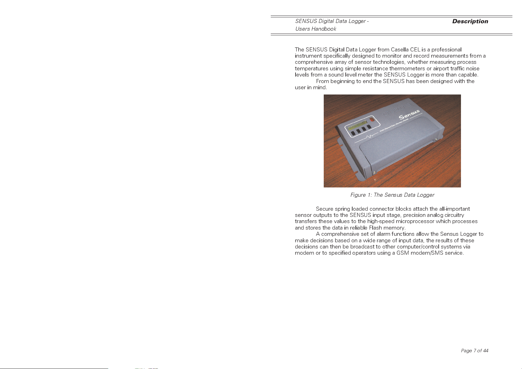
The SENSUS Digital Data Logger from Casella CEL is a professional
instrument specifically designed to monitor and record measurements from a
comprehensive array of sensor technologies, whether measuring process
temperatures using simple resistance thermometers or airport traffic noise
levels from a sound level meter the SENSUS Logger is more than capable.
From beginning to end the SENSUS has been designed with the
user in mind.
Figure 1: The Sensus Data Logger
Secure spring loaded connector blocks attach the all-important
sensor outputs to the SENSUS input stage, precision analog circuitry
transfers these values to the high-speed microprocessor which processes
and stores the data in reliable Flash memory.
A comprehensive set of alarm functions allow the Sensus Logger to
make decisions based on a wide range of input data, the results of these
decisions can then be broadcast to other computer/control systems via
modem or to specified operators using a GSM modem/SMS service.
Page 7 of 44
Operation
SENSUS Digital Data Logger -
Users Handbook
2. OPERATION
2.1 Getting Started
The easiest way to get the Sensus Logger up and running is to transfer a
new profile from the PC application Online Pro. With just a few mouse clicks
the Sensus Logger can be tailored to match the sensors used and begin
recording data within minutes.
2.2 Introduction
The Sensus is designed to start processing/logging data as soon as power is
applied to it and to continue to do so until power is removed. This means that
should power to the logger be interrupted for any reason, the unit will recover
and continue collecting data when power is restored without any user
intervention.
When the Sensus Logger is powered-up, it re-configures itself
automatically, based upon a set of operating parameters held in its internal
profile. Once the contents of the profile have been processed the logger
begins its task of collecting/logging data.
Most aspects of the loggers operation can be changed by the user,
either via the menu system or via the command line interface. Both of these
configuration tools are accessible via the RS232 command interface.
The factory default setting for the RS232 command interface is 9600
baud, 8 data bits, 1 stop bit, no parity and no handshake. The configuration
tools can be accessed manually using any terminal interface program, (such
as Hyperterm, as supplied with the WindowsTM operating system).
The menu system is more useful for manual reconfiguration where
a few parameters are to be changed or a new sensor added. The command
line interface is of more use where an automatic configuration is needed and
it is this approach that is used by the Online Pro application to provide
automated configuration. The menu system is activated by default but it can
switch between the two as and when required.
While the Sensus Logger is running it is at all times performing a
series of tasks in the background.
Sensor scanning: This task is performed at regular intervals
determined by the period set in the
profile. Each time it runs fresh data is
collected from the attached sensors, this
data is in turn processed to provide the
values logged by the system and used in
alarm comparisons.
Logging: Again, this task is performed at an interval
defined in the profile. While running, all
data values marked to be logged are
moved to a holding buffer then written
either to the internal memory or to
external CompactFlash card.
Alarms: At fixed intervals current data values are
compared against active alarm channels
Page 8 of 44
SENSUS Digital Data Logger -
Users Handbook
and alarm states and actions are updated
at this time.
Operation
2.3 Menu Interface
This interface is the default selection when the Sensus Logger is switched
on. The clear and easy to follow structure allows the user to redefine most
aspects of the loggers configuration with ease.
When navigating around the menu system the following rules apply.
Action Result
Pressing the Escape key This cancels the current operation and
causes the menu system to step back a
level without making any changes.
This can be done at any prompt.
Pressing the Backspace key
Deletes the last character entered from
the input buffer.
The Logger responds with Backspace-
Space-Backspace to remove character
from display.
Type a menu option number and press the Enter key
Executes the function associated with
that menu option number.
Typing text All typed text should be in lowercase
except where the text is contained in
quotes , here mixed case text can be
used.
All prompts limit the amount of text that
can be entered by the user, when this
limit is reached further characters are
ignored.
Typing an empty string Where a blank string needs to be entered
(for example, to clear the loggers ID text)
this can be achieved by typing a pair of
double quotes without any spaces
between ( ).
To read a value Select the menu option number for that
value, the menu system always prints the
current value before the prompt to
change it.
Once displayed press the Escape key.
To change a value Select the menu option number for that
value and when prompted for a new
value type it in and press the Enter key.
Continuous output Where the menu system is continuously
outputting values (data display option)
pressing the Escape key will terminate
the option and return control to the parent
menu.
Page 9 of 44
Operation
No activity If the menu system detects no user
activity for more than 60 seconds then it
will automatically terminate the current
option and return control to the parent
menu.
This ensures the menu system will return
to a safe state if communication should
fail. The only exception to this is where
the user has selected continuous output.
SENSUS Digital Data Logger -
Users Handbook
2.4 Auto Transmit Mode
A special feature of the menu interface, is the availability of an Auto Transmit
mode, for use where data must be sent by the Sensus at regular intervals
without further user intervention.
When enabled, the Sensus will wait at the main menu prompt for a
specified period of inactivity. When this occurs, the current data values are
collected and transmitted over the command interface together with an 8-bit
checksum value. This data collection and transmission sequence is repeated
at a specified rate until command activity is detected, at which time, the main
menu regains control of the interface.
2.5 Command Line Interface
This interface can be activated at any time from an option in the top-level
menu of the menu interface. Once activated the menu system is suspended
until the command line interface is closed, which is achieved by pressing the
Escape key when at the command line prompt.
The command line interface represents itself by displaying a single
greater- than character (>), this is the command line prompt.
Commands are entered in lowercase (except for quoted text which
can have mixed cases). Each command consists of two parts, the command
name and its parameters. The parameters are separated from the command
name by enclosing them in round brackets ( () ).
Typing a question mark ( ? ) allows the user to search for likely
commands followed by some portion of the command name, some
command search examples are given here:
Search pattern Result
>?date setdate
>?rate setscanrate
setfastscanrate
setlograte
setfastlograte
Some examples of command formats are given below.
Command Function
>setloggeridtext(Test field 1) Set the loggers id text to
Test field 1"
>setchandesc(1,Cabinet humidity) Set the channel description
for data channel 1 to
Cabinet humidity
Page10of44
SENSUS Digital Data Logger -
Users Handbook
>setchanpolynomial(1,0.0,1.23) Set the scaling polynomial
for data channel 1 to
C=0.0, X1=1.23
As with other prompts, if the logger detects no user activity for 60 seconds,
then the command line interface terminates and control returns to the menu
interface, top level.
Operation
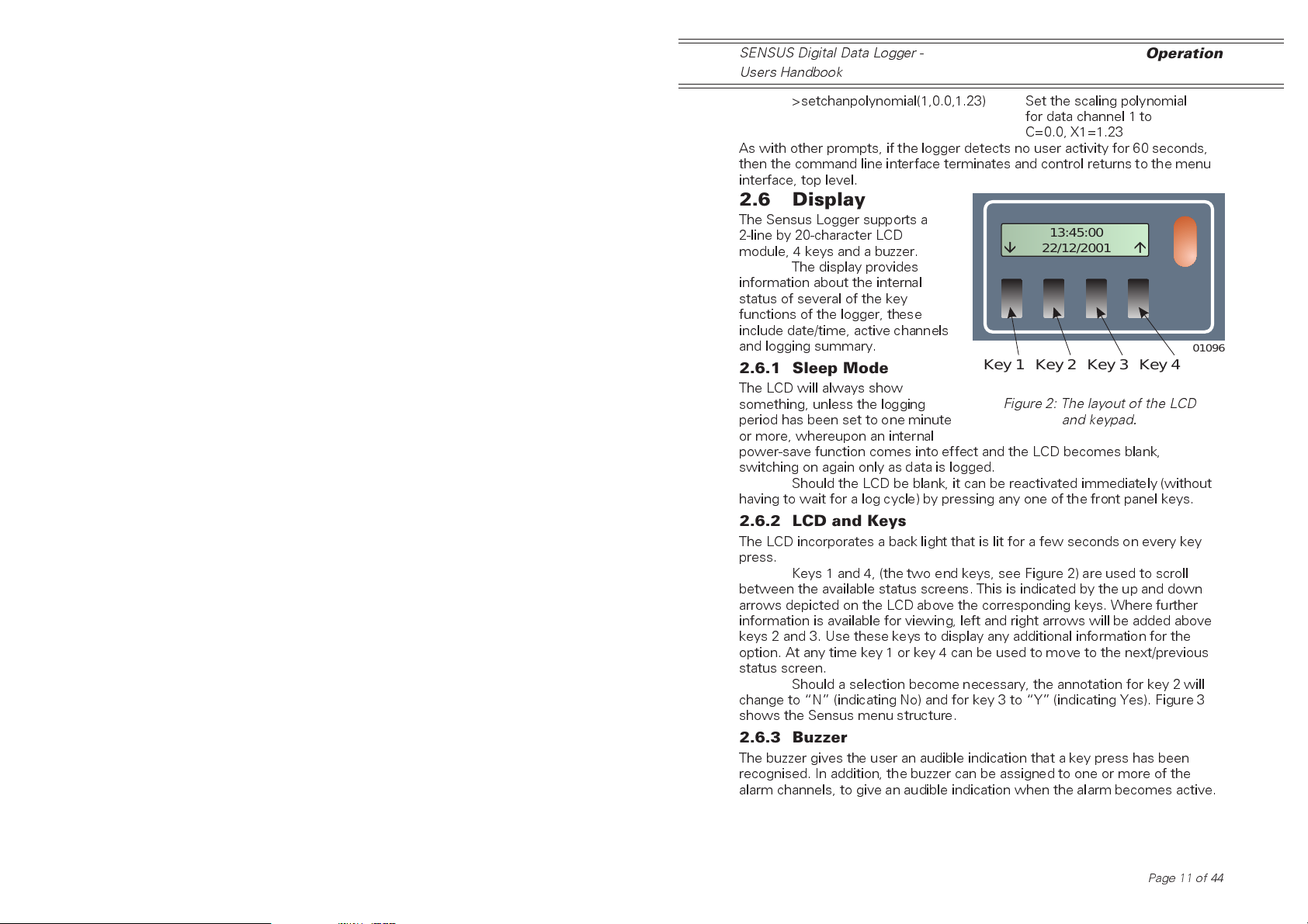
2.6 Display
The Sensus Logger supports a
2-line by 20-character LCD
module, 4 keys and a buzzer.
The display provides
information about the internal
status of several of the key
functions of the logger, these
include date/time, active channels
and logging summary.
2.6.1 Sleep Mode
The LCD will always show
something, unless the logging
period has been set to one minute
or more, whereupon an internal
power-save function comes into effect and the LCD becomes blank,
switching on again only as data is logged.
Should the LCD be blank, it can be reactivated immediately (without
having to wait for a log cycle) by pressing any one of the front panel keys.
Key 1 Key 2 Key 3 Key 4
2.6.2 LCD and Keys
The LCD incorporates a back light that is lit for a few seconds on every key
press.
Keys 1 and 4, (the two end keys, see Figure 2) are used to scroll
between the available status screens. This is indicated by the up and down
arrows depicted on the LCD above the corresponding keys. Where further
information is available for viewing, left and right arrows will be added above
keys 2 and 3. Use these keys to display any additional information for the
option. At any time key 1 or key 4 can be used to move to the next/previous
status screen.
Should a selection become necessary, the annotation for key 2 will
change to N (indicating No) and for key 3 to Y (indicating Yes). Figure 3
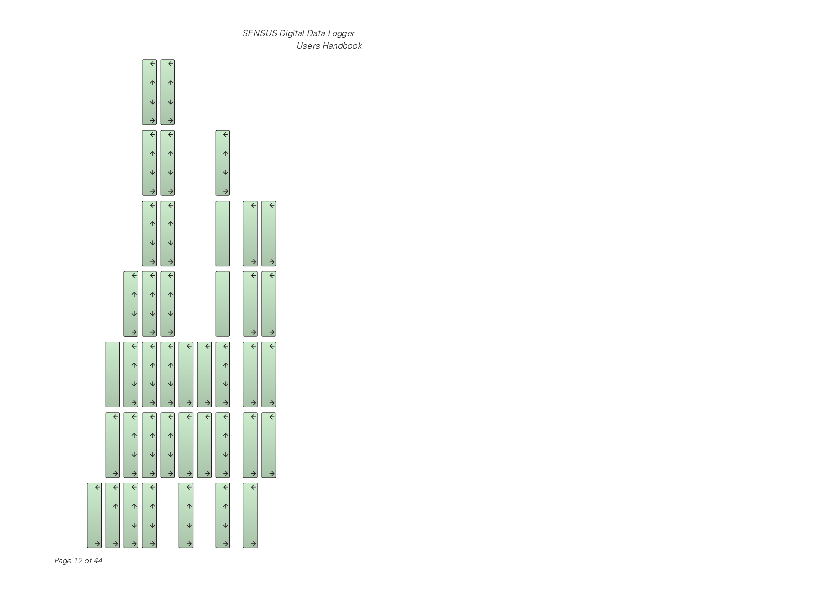
shows the Sensus menu structure.
2.6.3 Buzzer
The buzzer gives the user an audible indication that a key press has been
recognised. In addition, the buzzer can be assigned to one or more of the
alarm channels, to give an audible indication when the alarm becomes active.
13:45:00
22/12/2001
01096
Figure 2: The layout of the LCD
and keypad.
Page 11 of 44
Operation
13:30:00, 15/12/2001
13:30:00, 15/12/2001
Last record:
Last record:
SENSUS Digital Data Logger -
Users Handbook
02018
995.0 mbar
Ch: 07,
...
Figure 3: Menu Structure of the Sensus data logger
13:45:00
Page12of44
installed in the Casella Nomad weather station
Switching off
N
Y
Switch off ?
22/12/2001
Power control
Supply: 13.6 V
o
Temp.: +22.7 C
80-XXXXXXA-22
System information
03:10:00, 30/06/2001
03:10:00, 30/06/2001
First record
First record
254
254
Int. record count:
Ext. record count:
Logging information
See note 1
(Run)
Enabled (paused)
(Pause)
Enabled
Logging control
(Run)
Disabled (paused)
(Pause)
Disabled
See note 2
Ch:...
...
Ch:...
1.3 m/s
Ch: 02,
0.0 mm
Ch: 01,
Data values
See note 3
CF card ? version ?
CF card ? serial ?
CF card present
CF card detected
CF slot empty
CF card error
CF card full
CF card ? unknown ?
CF card *BUSY*
If a CF card is present in the slot when this option is selected, then the six screens will display information relating to the data stored on the card.
Notes 1.
If there is no card present, the screens will display information relating to data stored internally in the Sensus logger.
If logging is currently enabled, then the top two screens will be shown. When logging is NOT enabled, the bottom two will be shown.
The CF display screens change automatically, depending on the current state of the CF card installed (if any). Apart from inserting or removing a
CF card, the user has no control over which of these screens is displayed.
2.
3.

SENSUS Digital Data Logger -
Users Handbook
Commands
3. COMMANDS
A full and detailed description of all the commands available on the Sensus
Logger is beyond the scope of this handbook. When this information is
essential to your particular application, please contact Casella CEL and
request a copy of the document: Sensus - A Programmers Guide (HB3291).
3.1 Data Channels
The configuration information stored in a data channel controls how input
data is collected, processed and stored by the logger.
3.1.1 Channel Type
The channel type allocated to a data channel controls where the channel will
go in order to obtain real world measurements.
Allowable channel types are detailed below.
Data Channel Type Function
Analog Readings are taken from analog input
signals (differential or single-ended).
Counter Readings are taken from digital counter
inputs.
Data Readings are taken from other data
channels.
Instrument Readings taken from RS232 Inst. interface
Passive This data channel type does not obtain
readings itself, rather it waits to be
updated from other sources (for example
alarms).
Parameter Allows values held in the loggers
parameter space (system variables) to be
processed just like other data.
Options and settings that differ depending on the channel type selected will
be explained in greater detail in Section 2.2, Type Specific Configuration. The
following paragraphs describe options that are common to all channel types.
3.1.2 Description
The text allocated to the data channels description tells the user the physical
property actually being measured by the channel. The text is used to identify
the channel contents in alarm messages and other outputs.
3.1.3 Units
This text identifies the measuring units used when presenting data for the
channel. This is used in alarm messages, logging to CompactFlash cards
and LCD messages.
3.1.4 Display Format Specifier
The text allocated to this parameter controls how data values for the channel
are presented to the user. This specifier controls whether a value is signed,
the field width and the number of decimal places. Character positions are
indicated by the hash ( # ) or zero ( 0 ) characters. Some format specifier
examples are given below.
Page 13 of 44
Commands
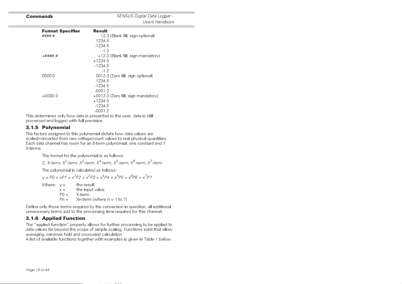
Format Specifier Result
####.# 12.3 (Blank fill, sign optional)
1234.5
-1234.5
-1.2
+####.# +12.3 (Blank fill, sign mandatory)
+1234.5
-1234.5
-1.2
0000.0 0012.3 (Zero fill, sign optional)
1234.5
-1234.5
-0001.2
+0000.0 +0012.3 (Zero fill, sign mandatory)
+1234.5
-1234.5
-0001.2
This determines only how data is presented to the user, data is still
processed and logged with full precision.
SENSUS Digital Data Logger -
Users Handbook
3.1.5 Polynomial
The factors assigned to this polynomial dictate how data values are
scaled/converted from raw voltage/count values to real physical quantities.
Each data channel has room for an 8-term polynomial, one constant and 7
X-terms.
The format for the polynomial is as follows:
C, X-term, X2-term, X3-term, X4-term, X5-term, X6-term, X7-term
The polynomial is calculated as follows:
y=P0+xP1+x2P2+x3P3 + x4P4 + x5P5+x6P6 + x7P7
Where: y = the result
x = the input value
P0 = X-term
Pn = Xn-term (where n = 1 to 7)
Define only those terms required by the conversion in question, all additional
unnecessary terms add to the processing time required for this channel.
3.1.6 Applied Function
The applied function property allows for further processing to be applied to
data values far beyond the scope of simple scaling. Functions exist that allow
averaging, min/max hold and crosswind calculation.
A list of available functions together with examples is given in Table 1 below.
Page14of44

SENSUS Digital Data Logger -
Users Handbook
Table 1: Available Functions
Commands
Function
Name
none none() None Input channel No additional
minhold minhold() None 1. Input Channel Holds most
maxhold maxhold() None 1.Input Channel Holds most
rollingavg rollingavg(60) 1.Averaging
vectoravg vectoravg(60) 1.Averaging
degreeday degreeday(30,gain) 1.Limit value
windto windto() None 1.Input Channel Convert input
crosswind crosswind() None 1.Wind speed
vapour vapour() None 1.Air
Example Parameters Input
Channels
period in
seconds
period in
seconds
2.
gain
-
accumulate
when value is
above limit
loss
-
accumulate
when value is
below limit
1.Input Channel Calculates
1.Input Channel Calculates
1.Input Channel Calculate solar
channel
2.Wind
direction
channel
3.Bearing
channel
temperature
2.Humidity
Result
processing is
performed,
output value
equals input
value
negative value
until reset
positive value
until reset
rolling average
over given
interval
vector average
over given
interval
gain (loss)
based on
percentage of
time (over 24
hours) that the
value exceeds
(is below) limit
value of
wind
from
direction
to output value
of
wind to
direction
Calculate cross
wind
component for
wind speed
using direction
and bearing
values
Calculate the
saturated
vapour
pressure for
the air
temperature
and humidity
values
Page 15 of 44

Commands
SENSUS Digital Data Logger -
Users Handbook
Function
Name
dewpoint() dewpoint() None 1.Vapour
sum() sum() None 1 to 4 input
Example Parameters Input
Channels
pressure
channels
Result
Calculate the
dew point for
the saturated
vapour
pressure value
Calculate the
sum of the
specified input
values
3.1.7 Flags
The flags setting controls yes/no (enable/disable) type options for the data
channel. Current options are given below.
Option Flag Set to Enabled Set to Disabled
Channel Channel is active
and processing
data. Channel data
can be included in
reports and further
processing.
Logging Channel data
should be included
in log events
Function Reset The function
associated with
this channel will
reset any running
calculation the next
time it is updated
(for example,
forced reset of
maximum hold)
Channel is inactive,
data is not updated
and is not included
in any reports.
Channel data is
ignored by log
events
No action
3.2 Type Specific Configuration
This option gives access to settings, which differ depending on the channel
type selected.
3.2.1 Input Channel
Where a channel must obtain data values from an input source (analog input
or other data channel) the number associated with that source is set here.
For
analog
For single-ended types this can be positive for the positive input channel, or
negative for the negative input channel. For differential input channels, the
value is always positive. The allowable range is from 1 to the maximum
number of analog channels.
For
digital
to be used. The allowable range is 1 to 4.
Page16of44
type channels, this is the number of the analog input.
type channels, this is the number of the counter channel

SENSUS Digital Data Logger -
Users Handbook
For
data
type channels, this is the channel number of another data
channel whose data values will be further processed by this channel. The
allowable range is 1 to the maximum number of data channels.
For
parameter
whose value is to be further processed by the channel. The allowable range
is1to100.
type channels, this is the number of the parameter
Commands
3.2.2 Single-ended or Differential
This option applies only to analog type channels and determines whether the
associated analog channel will be read as a single-ended voltage input or as a
differential input. It should be set to match how the sensor is connected.
3.2.3 Gain Setting
Again only for analog type channels, it sets the gain to be applied to the input
analog signal before the logger converts it. The allowable options are shown
below.
Analog Gain Option Action
x1 Leave analog signal untouched,
full scale ±2.5 V.
x10 Multiply analog signal by a factor
of 10, full scale ±250 mV.
x100 Multiply analog signal by a factor
of 100, full scale ±25 mV.
3.2.4 Report Count or Frequency
This applies only to counter type channels and determines whether the
channel result will represent the pulse count for the measurement period or
the equivalent frequency value.
3.2.5 Counter Reset Mode
Again only for counter type channels, it sets when the count value is to be
reset. The allowable options are shown below.
Counter Reset Option Action
Reset on scan Reset the counter every time it is read in
the scan event.
Reset on log Reset the counter every time the log
event occurs.
Reset at midnight Reset the counter only at midnight
(for daily accumulated values).
3.2.6 Select Instrument Type
This option is only for instrument type channels and specifies the type of
instrument attached to the logger. It configures how the logger will talk to
the instrument and which data values it is to extract.
3.2.7 Set Data Value
Purely for passive type data channels which do not actively gather data from
other sources but merely presents data for other channels to read. This
option allows the data value held to be updated.
Page 17 of 44

Logging
SENSUS Digital Data Logger -
Users Handbook
4. LOGGING
By default, the Sensus logs data to its internal record store at an interval
specified by the user. If the logger detects the presence of a compatible
CompactFlash card, it automatically uses this instead. When the card is
removed, the logger reverts to using its internal store. For information on the
use of CompactFlash cards please refer to Section 8 on CompactFlash.
4.1 Log Rate
The logger operates with two logging rates, one normal rate and one fast
rate. Switching between these two rates is handled automatically by the
alarm system. For further information please refer to Section 12 on Alarms.
Both logging rates can be set to any value between 5 seconds and
24 hours.
4.2 What Gets Logged ?
Any data channel that has its log active flag set will be included when the
next log event occurs. Logging globally can be disabled/enabled by changing
the log active flag held in the logging configuration. This allows logging to
be suspended temporarily without changing all the channel flags.
4.3 Internal Capacity
The Sensus Logger has 512 kBytes of internal Flash storage available to hold
logged information. This store is updated in a first-in-first-out manner so that
the earliest records are always being replaced with the newest ones. While
this means the logger will never stop recording data, only a set period of time
will remain available for collection at any time.
The number of records held and the period of time covered by the
internal store depend on both the number of channels being logged and the
logging interval.
The following equations let the user calculate the record capacity
and the store duration.
524288
74+=()
Channels x
Re cord Capacity x Logging Interval Store Duration=
These equations should be used only as a guideline as the logging interval
may change during operation, especially if the fast mode option has been
enabled in the alarms.
Some example internal result capacities are shown in Table 2.
Page18of44
Re
cord Capacity

SENSUS Digital Data Logger -
Users Handbook
Table 2: Internal Store Capacity (512 kB)
Logging
Number of
Channels
1 1 47662 33 days
1 10 47662 33 days
1 60 47662 5.4 years
7 1 14979 10 days
7 10 14979 104 days
7 60 14979 1.7 years
24 1 5090 3.5 days
24 10 5090 35 days
24 60 5090 212 days
Logging Interval
(mins)
Record Capacity Storage Capacity
4.4 External Capacity
When logging to external media such as CompactFlash cards, the store is
updated with data being added to the card until it becomes full. Logging will
then stop until the card has been replaced with an empty one.
The following equations let the user calculate the record capacity
and the store duration for external media.
(.)
Capacity in MB x x
74+
Re cord Capacity x Logging Interval Store Duration=
Again, these equations should be used only as a guideline, for the
same reasons as given for the internal store and also because of the
approximation that only 95% of the cards capacity is available for actual data
storage. Some example CompactFlash result capacities are given in Table 3.
1048576 0 95
()
Channels x
Re
=
cord Capacity
Table 3: External Store Capacity (16 MB)
Number of
Channels
1 1 1448941 2.7 years
1 10 1448941 27 years
1 60 1448941 165 years
7 1 455381 316 days
7 10 455381 8.6 years
7 60 455381 51 years
24 1 154741 107 days
24 10 154741 2.9 years
24 60 154741 17 years
Logging Interval
(mins)
Record Capacity Storage Capacity
Page 19 of 44

Input Connections
SENSUS Digital Data Logger -
Users Handbook
5. INPUT CONNECTIONS
Removing the connector cover plate gives access to the input connector
array. The connector array consists of 3, 4 and 5-way detachable connector
blocks to which sensor outputs are wired. The combination of spring-clamp
technology and plug-in modules allow for rapid and secure attachment of a
variety of sensors.
Figure 4: The logger with cover removed
Channel numbering starts from the left-side, bottom-row and
alternates between the bottom and top row, from left to right. In addition the
pins of each connector are numbered from left to right.
4
+A
3
+A
+Vsw
+Vsw
0V
V
0
6
8
V
+A
+A
0
8
6
+Vsw
-A
-A
7
5
-A
-A
5
+A
+Vsw
0V
7
+A
2
V
+A
0V
0
4
2
+Vsw
-A
-A
AN2 AN4 AN6 AN8 AN10 AN12 CNT2 CNT4 AN.OUT
AN1 AN3 AN5 AN7 AN9 AN11 CNT1 CNT3 ALARMS
3
1
-A
-A
1
V
V
0
0
+Vsw
+A
I2
+Vsw
I1
+Vsw
V
0
0V
0
1
0
+A
1
-A
9
-A
9
+A
I4
+Vsw
I3
+Vsw
0V
0V
2
1
2
I6
+A
1
-A
1
1
1
-A
1
+A
+Vsw
I5
+Vsw
0V
0V
+V
0V
C2
C1
V
0
+V
2
A
+V
VSS
1
A
C4
1
L
C3
2
A
L
0V
+V
A
CTS
RXD
0V
RS232 SOLAR
CHARGER BATT
0V
TXD
V
0
DTR
G
+CH
G
+CH
-SP
0V
Figure 5: The connector cover label
A copy of this connector/pin assignment diagram is located on the
reverse of the connector cover plate for reference in the field.
Page20of44
+SP
RS485
0V
-A
-B
G
G
+CH
+CH
01072

SENSUS Digital Data Logger -
Users Handbook
5.1 Wire Preparation and Insertion
To insert a wire into a spring terminal,
first strip back the insulation leaving
10 mm of bare wire exposed as
shown in Figure 6.
01083
Use a small
i
screwdriver to
ii
depress the
iii
orange clamp
iiii
while inserting
iiiii
the stripped
iiiiii
end of the
iiiiiii
conductor
01084
Figure 7: Depressed clamp
while inserting wire
Using a small flat headed screw-
driver (or similar) fully depress the
orange plunger located above the
hole into which the wire is to be
inserted and insert the wire into the
hole as far as it will go, as shown in
Figure 7.
Figure 6: Stripped wire
Remove the
i
screwdriver to
ii
iii
iiii
iiiii
Stripped
10 mm
Conductori
release the
clamp and
grip the
conductor
Logging
Release the orange plunger and the
wire is held captive by the connector
(Figure 8).
A gentle tug on the wire will
confirm that it is held firmly.
01085
Figure 8: Wire firmly clamped
5.2 Differential/Single-ended
Each analog connector has available 2-inputs that must be connected as a
pair where a differential signal is to be measured. Alternatively, they can be
wired to 2 independent single-ended signals and measured separately.
When the logger is configured to read 2 independent signals in this
way, the polarity inversion of the negative input is automatically compensated
before the readings are processed further.
Page 21 of 44

Logging
5.3 Analog 4-way Connectors
SENSUS Digital Data Logger -
Users Handbook
The first 3 connectors of each row of
the connector array are intended
specifically for analog channels. They
have the following pin assignments.
Figure 9: 4-way connector
4-way connectors - AN1 to AN6
0 V Analog signal ground reference,
-Ax Differential connection negative input,
+Ax Differential connection positive input,
+Vsw 13.8 V switched supply for sensor
excitation. This excitation voltage is
common to all analog sensor connectors.
5.4 Analog 5-way Connectors
The next 3 connectors of each row of
the connector array are also intended
specifically for analog channels. They
have the following pin assignments:
0V
-Ax
+Ax
+Vsw
01073
0V
-Ax
+Ax
+Vsw
ly
5-way connectors - AN7 to AN12
0 V Analog signal ground reference,
-Ax Differential connection negative input,
+Ax Differential connection positive input,
+Vsw 13.8 V switched supply for sensor
Iy 200 µA sensor excitation (this excitation
Page22of44
01074
Figure 10: 5-way connector
excitation. This excitation voltage is
common to all analog sensor connectors.
current can be switched between each of
these 5-way connectors).

SENSUS Digital Data Logger -
Input Connections
Users Handbook
5.5 Counter 3-way Connectors
The next 2 connectors of each row of
the connector array are dedicated to
counter channels. They have the
following pin assignments.
01075
Figure 11: 3-way connector
3-way connectors - CNT1 to CNT4
0 V Analog signal ground reference,
Cx Counter input,
+V Permanent 13.8 V supply for sensor
excitation This excitation voltage is
common to all counter sensor connectors.
5.6 Connection Examples
The following set of figures show wiring schemes for some of the more
common input configurations:
0V
Cx
+V
5.6.1 Differential Input
5.6.2 Single-ended Inputs
01076
Figure 12: Differential connection to
4-way analog
01088
Figure 13: 2-single-ended signals
connected to 4-way analog
Page 23 of 44
?
?
?
?
?
?
?
?

Input Connections
SENSUS Digital Data Logger -
Users Handbook
5.6.3 4 to 20 mA
Current
5.6.4 4-Wire Resistive
PRTD
5.6.5 Counter
?
?
?
?
100R
01089
Figure 14: Signal connected for
4to20mAinput
R
01090
Figure 15: 4-wire PRTD connected to
current excitation with differential
measurement (5-way analog)
?
Page24of44
01091
Figure 16: Counter connected to
3-way counter
SENSUS Digital Data Logger -
Users Handbook
Communications
6. COMMUNICATIONS
The Sensus Logger is fitted with several communications interfaces, two RS
232 and one RS 485. These interfaces allow both control of the logger via
different media and data to be logged from other instruments with similar
interfaces.
6.1 RS 232 Command
The primary command interface to the Sensus Logger is located on the right
hand end of the logger case, marked RS 232 Command". This 9-way D-type
connector has the same pin-out as a similar 9-way connector found on most
modern PCs.
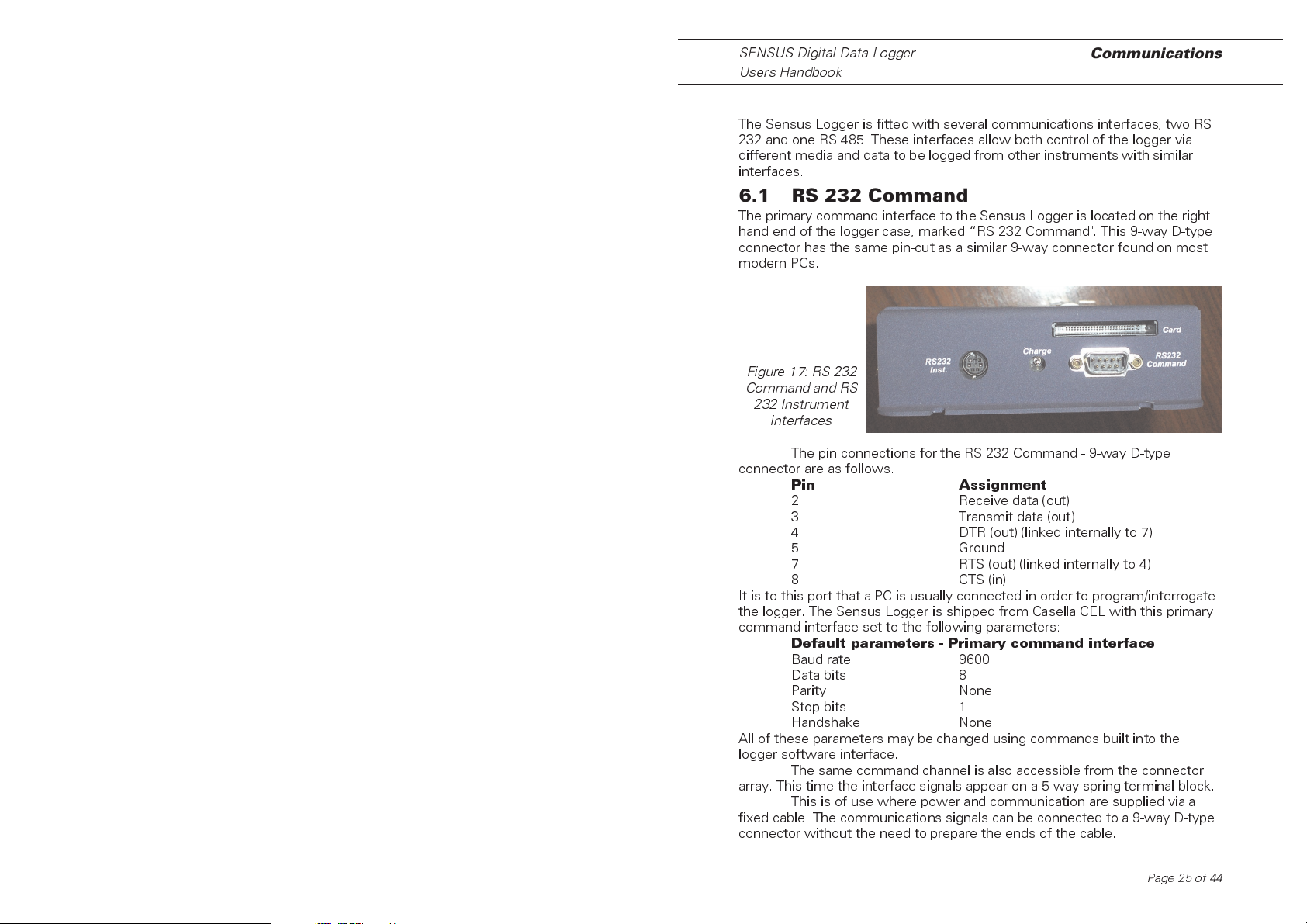
Figure 17: RS 232
Command and RS
232 Instrument
interfaces
The pin connections for the RS 232 Command - 9-way D-type
connector are as follows.
Pin Assignment
2 Receive data (out)
3 Transmit data (out)
4 DTR (out) (linked internally to 7)
5 Ground
7 RTS (out) (linked internally to 4)
8 CTS (in)
It is to this port that a PC is usually connected in order to program/interrogate
the logger. The Sensus Logger is shipped from Casella CEL with this primary
command interface set to the following parameters:
Default parameters - Primary command interface
Baud rate 9600
Data bits 8
Parity None
Stop bits 1
Handshake None
All of these parameters may be changed using commands built into the
logger software interface.
The same command channel is also accessible from the connector
array. This time the interface signals appear on a 5-way spring terminal block.
This is of use where power and communication are supplied via a
fixed cable. The communications signals can be connected to a 9-way D-type
connector without the need to prepare the ends of the cable.
Page 25 of 44
Commuications
SENSUS Digital Data Logger -
Users Handbook
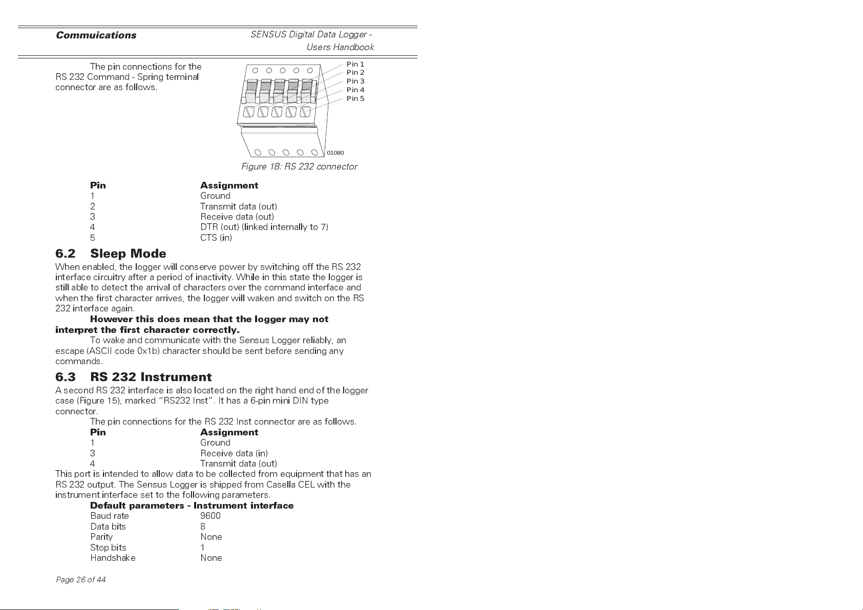
The pin connections for the
RS 232 Command - Spring terminal
connector are as follows.
Pin 1
Pin 2
Pin 3
Pin 4
Pin 5
01080
Figure 18: RS 232 connector
Pin Assignment
1 Ground
2 Transmit data (out)
3 Receive data (out)
4 DTR (out) (linked internally to 7)
5 CTS (in)
6.2 Sleep Mode
When enabled, the logger will conserve power by switching off the RS 232
interface circuitry after a period of inactivity. While in this state the logger is
still able to detect the arrival of characters over the command interface and
when the first character arrives, the logger will waken and switch on the RS
232 interface again.
However this does mean that the logger may not
interpret the first character correctly.
To wake and communicate with the Sensus Logger reliably, an
escape (ASCII code 0x1b) character should be sent before sending any
commands.
6.3 RS 232 Instrument
A second RS 232 interface is also located on the right hand end of the logger
case (Figure 15), marked RS232 Inst. It has a 6-pin mini DIN type
connector.
The pin connections for the RS 232 Inst connector are as follows.
Pin Assignment
1 Ground
3 Receive data (in)
4 Transmit data (out)
This port is intended to allow data to be collected from equipment that has an
RS 232 output. The Sensus Logger is shipped from Casella CEL with the
instrument interface set to the following parameters.
Default parameters - Instrument interface
Baud rate 9600
Data bits 8
Parity None
Stop bits 1
Handshake None
Page26of44

SENSUS Digital Data Logger -
Users Handbook
All of these parameters may be changed using commands built into the
logger software interface.
Communications
6.4 RS 485 Command Alternate
The Sensus Logger also has an RS 485
interface accessible from the connector array
(Figure 19). The signals are available from a
2-way spring terminal block.
This interface can be used as an
alternate to the primary command interface
(RS232) where longer distances exist.
The pin connections for the RS 485
alternate command interface connector are as
follows.
Figure 19: RS 485 interface
Pin Assignment
1 A (-)
2 B (+)
The Sensus Logger is shipped from Casella CEL with this instrument
interface set to the following parameters.
Default parameters - RS485 alternate command interface
Baud rate 9600
Data bits 8
Parity None
Stop bits 1
Handshake None
All of these parameters may be changed using commands built into the
logger software interface.
Pin 1
Pin 2
01081
6.5 Modems
The Sensus Logger is pre-configured with a generic set of command/
response strings suitable for most Hayes-compatible modems. If the modem
used differs from this standard, these strings will need to be altered to match
the new configuration.
In addition, all command/response time-out values are also
configurable for those instances where the default values are insufficient for
the equipment used.
Page 27 of 44
CompactFlash Cards
SENSUS Digital Data Logger -
Users Handbook
7. COMPACTFLASH™ CARDS
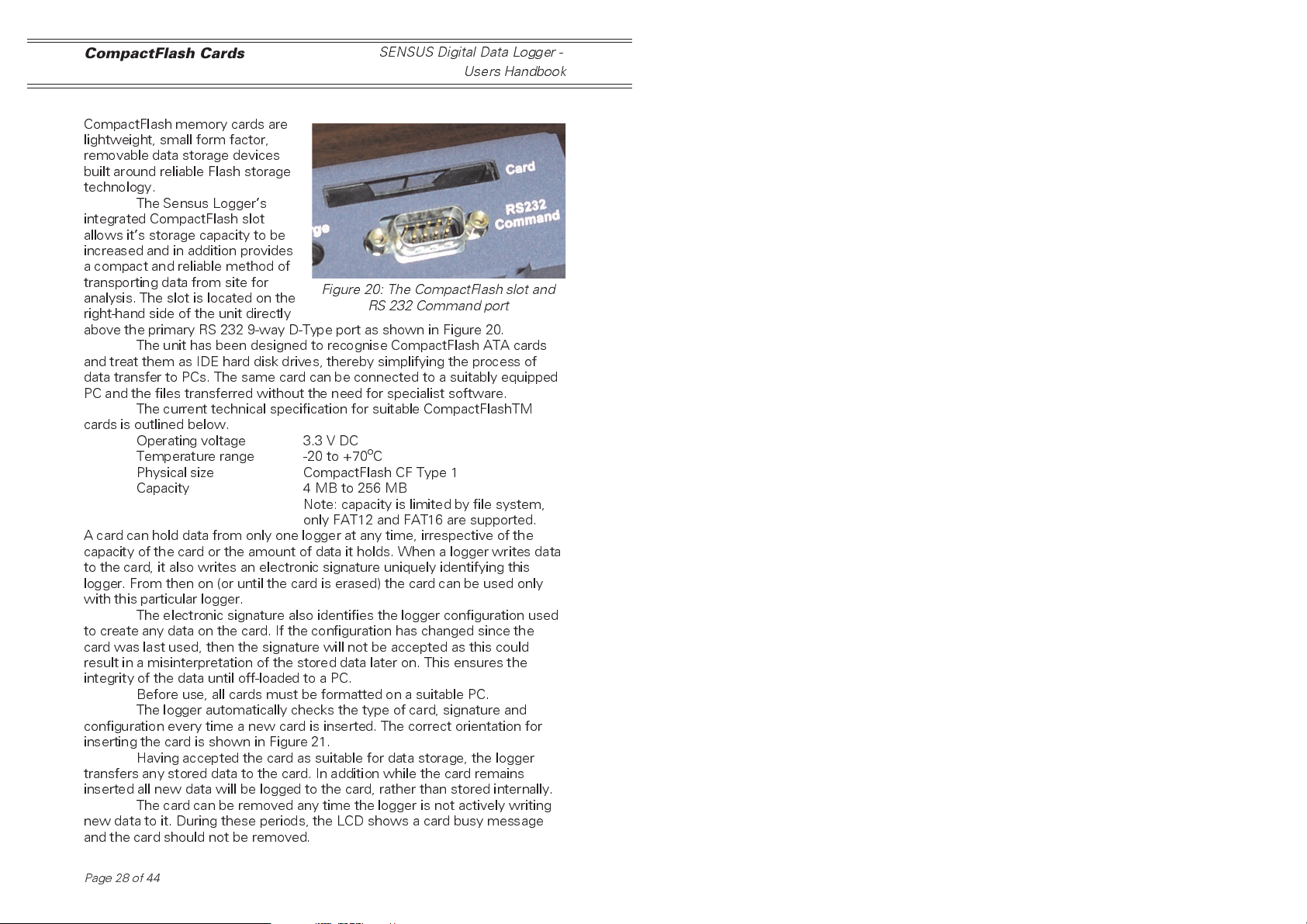
CompactFlash memory cards are
lightweight, small form factor,
removable data storage devices
built around reliable Flash storage
technology.
The Sensus Loggers
integrated CompactFlash slot
allows its storage capacity to be
increased and in addition provides
a compact and reliable method of
transporting data from site for
analysis. The slot is located on the
right-hand side of the unit directly
above the primary RS 232 9-way D-Type port as shown in Figure 20.
The unit has been designed to recognise CompactFlash ATA cards
and treat them as IDE hard disk drives, thereby simplifying the process of
data transfer to PCs. The same card can be connected to a suitably equipped
PC and the files transferred without the need for specialist software.
The current technical specification for suitable CompactFlashTM
cards is outlined below.
Operating voltage 3.3 V DC
Temperature range -20 to +70oC
Physical size CompactFlash CF Type 1
Capacity 4 MB to 256 MB
A card can hold data from only one logger at any time, irrespective of the
capacity of the card or the amount of data it holds. When a logger writes data
to the card, it also writes an electronic signature uniquely identifying this
logger. From then on (or until the card is erased) the card can be used only
with this particular logger.
The electronic signature also identifies the logger configuration used
to create any data on the card. If the configuration has changed since the
card was last used, then the signature will not be accepted as this could
result in a misinterpretation of the stored data later on. This ensures the
integrity of the data until off-loaded to a PC.
Before use, all cards must be formatted on a suitable PC.
The logger automatically checks the type of card, signature and
configuration every time a new card is inserted. The correct orientation for
inserting the card is shown in Figure 21.
Having accepted the card as suitable for data storage, the logger
transfers any stored data to the card. In addition while the card remains
inserted all new data will be logged to the card, rather than stored internally.
The card can be removed any time the logger is not actively writing
new data to it. During these periods, the LCD shows a card busy message
and the card should not be removed.
Figure 20: The CompactFlash slot and
RS 232 Command port
Note: capacity is limited by file system,
only FAT12 and FAT16 are supported.
Page28of44

SENSUS Digital Data Logger -
Users Handbook
CompactFlash Cards
Once removed, the
card can be inserted into a
suitably equipped PC and the
data and control files copied
in exactly the same way as
any other disk drive.
Narrow Slot
Connector
Wide Slot
Figure 21: Correct orientation for
inserting a CompactFlash card
01095
Page 29 of 44

Alarms
SENSUS Digital Data Logger -
Users Handbook
8. ALARMS
The Sensus Logger includes a comprehensive set of rules that can be used
individually or in combination to detect alarm conditions. These alarm
conditions can then cause one or more actions to be taken by the logger.
These actions include an audible warning, external alarm triggering, changing
the logging rate and remote message transmission via modem and SMS.
Each of the 16 alarm channels can be programmed in isolation or
combined for greater flexibility. The following sections describe how each
parameter of these alarms work and how it can be programmed
8.1 ID Text
Each alarm can be allocated a piece of descriptive text, which gets
transmitted during remote message and SMS alarm conditions. This text can
be used to identify the particular alarm causing the transmission when more
than one alarm is active on the logger.
In addition, each remote message is also prefixed with the loggers own ID
text and ID number allowing immediate or automatic identification of the
alarm source at the receiving end.
8.2 Input Channel
Each alarm channel monitors a single input data source and processes the
value of this data against its own set of rules. The data source can be any
one of the available data channels, analog, counter or calculated. Irrespective
of channel type, the alarms work solely on its current value.
8.3 Test Mode
This describes the logical comparison to be applied by the alarm to its
selected data value. The logical result of this comparison will determine
whether the alarm condition is active or not.
The available test modes are listed below.
Alarm Test mode
Mode Result,
none Alarm always returns false,
eq Alarm true if data value equals limit value,
neq Alarm true if data value not equal to limit
value,
gt Alarm true if data value greater than limit
value,
lt Alarm true if data value less than limit
value,
lt or gt Alarm true if data value less than first
limit value or greater than second limit
value,
gt and lt Alarm true if data value greater than first
limit value and less than second limit
value.
Page30of44

SENSUS Digital Data Logger -
Users Handbook
Alarms
8.4 Limits
Each alarm channel can compare its data value to either one or two limit
values depending on the test mode selected. For test modes that require
only a single limit value, the data is compared against the first limit value
allocated to the channel. For two limits, it is compared against both.
Both the data and limit values are held in floating-point format, so
some care should be exercised when using the eq test mode as the values
may not be exactly equal (displayed values are usually truncated after a few
decimal places).
8.5 Action
Alarms can be used either in isolation or combined with others for more
complex situations. The action parameter for an alarm defines how it
interacts with the next defined alarm channel. Available action modes are
listed below.
Alarm Action Mode
Mode Result,
none Alarm is acting in isolation,
or Alarm result should be logically ord with
the result of the next defined alarm,
and Alarm result should be logically andd
with the result of the next defined alarm.
Any single alarm, or the last alarm in a logical chain, should have its
action mode set to none. Only those alarms with an action mode none will
actually trigger an alarm event.
8.6 On/Off Delays
The resultant alarm condition can be filtered with respect to time by defining
on/off delays for the alarm channel. These delays are expressed in seconds
and can be set to any value between 0 and 65535 (approximately 18 hours).
A value of zero means the change of alarm condition will be
processed immediately it occurs. Any other value means the alarm condition
must remain steady in that state for the specified period of time before the
change of condition is processed. Any change of alarm condition within the
specified time period will cause the delay time to be counted again.
8.7 On/Off Values
Each alarm channel can be allocated a pair of data values that it can pass on
to a data channel whenever the alarm changes state. This allows alarm states
to be logged, displayed, used to control the actions of other alarms and affect
the processing of other data values.
8.8 Output Channel
This defines the data channel into which the on/off values are to be written
when the alarm changes state. This should be the channel number of a
passive type channel, as all other channel types automatically collect their
data values during the scan process. To disable this feature, refer to the
section on alarm flags.
Page 31 of 44
Alarms
SENSUS Digital Data Logger -
Users Handbook
8.9 Digital Output
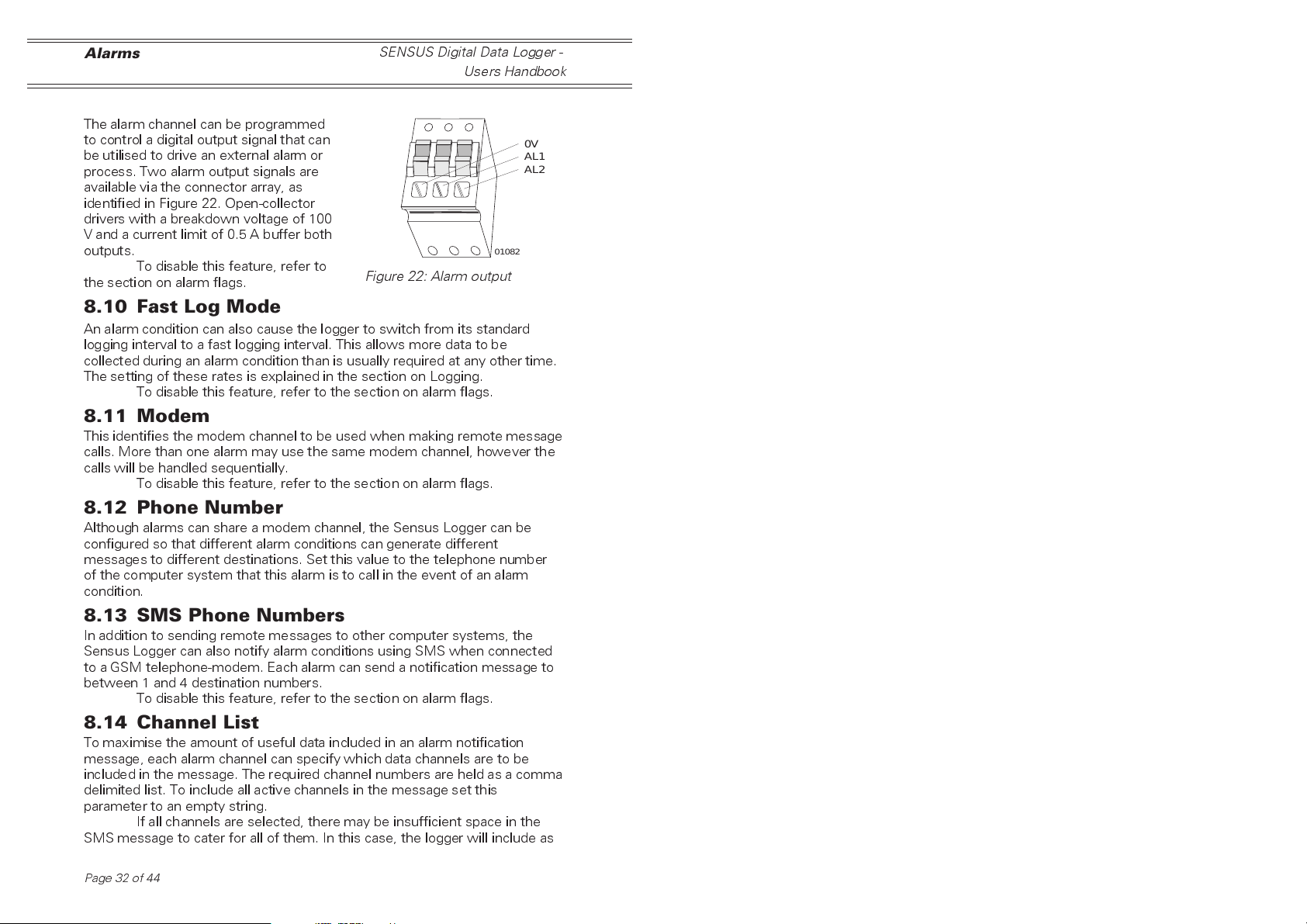
The alarm channel can be programmed
to control a digital output signal that can
be utilised to drive an external alarm or
process. Two alarm output signals are
available via the connector array, as
identified in Figure 22. Open-collector
drivers with a breakdown voltage of 100
V and a current limit of 0.5 A buffer both
outputs.
To disable this feature, refer to
the section on alarm flags.
Figure 22: Alarm output
0V
AL1
AL2
01082
8.10 Fast Log Mode
An alarm condition can also cause the logger to switch from its standard
logging interval to a fast logging interval. This allows more data to be
collected during an alarm condition than is usually required at any other time.
The setting of these rates is explained in the section on Logging.
To disable this feature, refer to the section on alarm flags.
8.11 Modem
This identifies the modem channel to be used when making remote message
calls. More than one alarm may use the same modem channel, however the
calls will be handled sequentially.
To disable this feature, refer to the section on alarm flags.
8.12 Phone Number
Although alarms can share a modem channel, the Sensus Logger can be
configured so that different alarm conditions can generate different
messages to different destinations. Set this value to the telephone number
of the computer system that this alarm is to call in the event of an alarm
condition.
8.13 SMS Phone Numbers
In addition to sending remote messages to other computer systems, the
Sensus Logger can also notify alarm conditions using SMS when connected
to a GSM telephone-modem. Each alarm can send a notification message to
between 1 and 4 destination numbers.
To disable this feature, refer to the section on alarm flags.
8.14 Channel List
To maximise the amount of useful data included in an alarm notification
message, each alarm channel can specify which data channels are to be
included in the message. The required channel numbers are held as a comma
delimited list. To include all active channels in the message set this
parameter to an empty string.
If all channels are selected, there may be insufficient space in the
SMS message to cater for all of them. In this case, the logger will include as
Page32of44

SENSUS Digital Data Logger -
Users Handbook
many as it can in the available space and ignore the rest. Data values are
formatted according to the pre-set display format string. To maximise the
number of channels included in the message, the display format should be
set with the minimum number of decimal places required to display the data
values correctly.
Alarms
8.15 Alarm Flags
Rather than removing the details associated with unused alarm options, each
option can be individually enabled/disabled using the relevant alarm flag. If an
option does not appear to be working, then check that the relevant flag has
been enabled before checking other settings.
Page 33 of 44

Analog Output
9. ANALOG OUTPUT
The Sensus Logger provides two analog
signals derived from internal PWM (pulse
width modulation) circuitry. These signals
can be accessed from the connector array as
shown in Figure 22.
These PWM outputs directly mimic
the value contained in a specified data
channel. As the data value changes, the
PWM output also changes to match it.
The following points should be
noted about these PWM outputs.
¤
The data value is interpreted as meaning volts, that is a data value of
0.5 will generate a voltage of 0.5 V.
¤
Only a positive signal can be generated by the PWM circuitry and
this is limited to between 0 and 5 V.
Data values below zero will be limited to zero and those above 5 will
be limited to 5 V.
¤
The resolution of the PWM output is fixed at 10-bits (0 to 1023)
giving a voltage resolution of 4.88 mV.
¤
While the PWM outputs are updated every 50 ms, the data channel
it mimics is updated at most only once a second.
¤
Excessive loading of the PWM output may result in reduced
amplitude and possibly oscillation.
Depending on the length of cable, an external buffer may be required.
SENSUS Digital Data Logger -
Users Handbook
0V
A1
A2
01092
Figure 23: The PWM
connector
Page34of44

SENSUS Digital Data Logger -
Users Handbook
Integrated Sensors
10. INTEGRATED SENSORS
The Sensus has the capacity to house two integrated sensors within the
logger case. Temperature measurement is installed as standard and
barometric pressure is available as an option.
10.1 Temperature
The temperature sensor is integrated into the design of the logger circuit
board and therefore is available at all times. The value from this sensor is
read every 10 seconds and held within the loggers parameter space for use
by the system.
The current value can be read from the System information status
screen on the LCD.
This value can also be accessed for logging and alarm comparison by
defining a parameter type data channel, then setting the input channel
number to point to the associated parameter number, in this case parameter
number 59.
The temperature is presented as degrees Celsius but by assigning a
different polynomial to the data channel the final readings can be set to other
measurement scales, see below.
Temperature Polynomials
Scale required Polynomial (C,M)
Degrees Celsius 0,1
Degrees Fahrenheit 32,1.8
Degrees Kelvin 273.15,0
10.2 Barometric Pressure
The optional barometric pressure sensor and its associated circuitry are
housed on a small PCB which can be installed piggy-back fashion on the
loggers main PCB within the loggers case (Figure 24).
When installed the signal
from the sensor replaces any
signal fed into analog channel
+A1. The corresponding negative
input -A1 is still available and can
be used for another single-ended
input source.
Once installed analog
channel +A1 can be switched
between the pressure signal and
any signal fed in on pin +A1 of
the connector array by moving
the position of a link (PL2) on the
loggers main PCB.
Figure 23 shows the
location of this link on the main
PCB. The PL2 link settings are
detailed below.
Barometer Circuit
Figure 24: Location of pressure PCB
PL2 Link
Page 35 of 44

Integrated Sensors
SENSUS Digital Data Logger -
Users Handbook
Jumper position Signal available on
analog channel +A1
Pins 1 - 2 (jumper to left) Barometric pressure
Pins 2 - 3 (jumper to right) Analog input +A1
By using a link to select the signal source for analog channel +A1,
the analog input can be reclaimed for an external signal without the need to
remove the barometric pressure sensor assembly.
The output from the pressure sensor is scaled at 1 mV per mbar.
Therefore in order to scale the data channel to show mbar, a polynomial of
0,1000 needs to be assigned (this scales the default reading of Volts to mbar).
Page36of44

SENSUS Digital Data Logger -
Users Handbook
11. POWER SUPPLIES
11.1 Solar Power
The Sensus Logger incorporates a solar
power regulator as standard. This
regulator is designed to operate in
conjunction with a nominal 12 V (30 W)
panel with a short circuit current of no
more than 2 A.
The solar panel should be wired
to the connector identified in Figure 25.
The pin assignments for the
solar panel connector are as follows.
Pin Assignment
1 Solar panel negative terminal,
2 Solar panel positive terminal.
11.2 Battery
The Sensus Logger incorporates a 12 V
lead-acid battery charger as standard.
This charger is designed to operate in
conjunction with a nominal 12 V lead-acid
battery and supplies a maximum charge
current of 0.5 A.
The lead-acid battery should be
wired to the connector identified in
Figure 26.
The pin assignments for the 12
V lead-acid battery connector are as
follows.
Pin Assignment
1 Battery negative terminal,
2 Battery positive terminal.
Power Supplies
Pin 1
Pin 2
01081
Figure 25: Solar power connector
Pin 1
Pin 2
01081
Figure 26: Battery connector
Page 37 of 44

Servicing
SENSUS Digital Data Logger -
Users Handbook
12. SERVICING
Casella CELs in house service department offers a comprehensive range of
repair and calibration services, designed to effect a fast and efficient back-up
for all our products. The Service Department is operated under the scope of
our BSI registration for products manufactured by us. We will however,
undertake the repair of other manufacturers equipment. For further
information please contact our service department at our Bedford
headquarters. We will be happy to provide quotations for individual repairs or
provide annual maintenance under contract.
We recommend factory service by technicians trained and equipped
to repair your instrumentation. Should you wish factory repair assistance,
send your equipment in a package equivalent to the original packaging. Insure
to full value and ship pre-paid. Include a letter giving full details with your
packing list.
Send to: Casella CEL Ltd
(Service Department)
Regent House
Wolseley Road
Kempston
Beds MK42 7JY
United Kingdom
For service outside the United Kingdom, please return to our appointed
distributor.
Page38of44

SENSUS Digital Data Logger -
Users Handbook
13. SPECIFICATION
13.1 Channel Information
Analog Channels:
12 differential analogue channels, each programmable as 2
independent single-ended channels, to give 12/24 from the main
connector panel.
4 differential analogue channels, each programmable as 2
independent single-ended channels, to give 4/8 from the expansion
port.
Numbers of differential and single-ended channels can be freely
mixed, up to the maximum number of channels available (16/32)
Input voltage ranges (measured resolution):
±2.5 V (±150 µV)
±250 mV (±24 µV)
±25 mV (±15 µV)
16-bit analogue to digital converter approx 20 ms per sample.
Switched (multiplexed) 13.8 V supply for sensor excitation.
Switched (multiplexed) 200 µA current source for sensor excitation.
Resistance measurements up to 12 kΩ. Suitable for 100 R PRTD
temperature sensors to 0.1% resolution.
Thermocouple interface under development.
Counter channels:
4 counter channels.
2 high speed and 2 medium speed.
Each channel can measure either accumulated count or frequency.
Input range:
Pulse count: 32-bit count, over scan period, logging
period or 24 hours.
Frequency: In excess of 100 kHz (high speed counter),
3 kHz (medium speed).
Inputs are 5 V logic compatible into Schmitt buffers (for slow edged
signals).
Medium speed counters continue to function when logger is in
power save (sleep) mode, high speed counters only function when
logger in full power mode.
Digital Channels:
Available via analogue channels (number of channels determined by
available analogue channels)
Specification
Page 39 of 44

Specification
Programmable threshold
Programmable data value (0/1, -1/+l)
SENSUS Digital Data Logger -
Users Handbook
Instrument Channel:
The unit has a single channel available to accept digital data
(via RS-232) from external instruments, including CEL sound level
meters. (Other instruments on request, development fee).
Passive Channels:
Software derived channels, which hold values entered via the user
command interface.
Can record manual readings and values from external automated
equipment.
Note: The number of passive channels available depends on the number of
unassigned data channels.
Data Channels:
64 data channels under software control to read:
Analogue
Digital
Pulse counter
Frequency
Instrument
Passive
Other data channels
Alarms
Data channels allow further manipulation of the available data before
it is logged or displayed. Each channel includes:
Description (Free text, Air temperature)
Units (Free text, Degrees C)
Display format (How the number is represented) Signed, fixed width,
leading zeros.
Eight-term polynomial (For scale, offset and linearisation of raw data)
Y = C + M1 *X + M2*X^2 ...+ M7*X^7
Data process function: including minimum hold, maximum hold,
average, vector average.
Analog Outputs:
2 analogue outputs derived from PWM (pulse width modulation)
signals. Any of the data channels can act as a source for the output
value.
Output voltage (0 to 5 V)
Resolution (10-bit : 1 in 1024)
Update period (50 mS)
Page40of44
SENSUS Digital Data Logger -
Users Handbook
Alarm Output Channels:
4 alarm output channels
2 available from the main connector panel 2 via expansion port
Primary channels (main connector):
These have open-collector outputs, suitable to drive relays on external
equipment.
Secondary channels (expansion port):
These are 5 V logic outputs, which require additional buffering
between them and any external equipment.
Alarm Channels:
16 alarm channels, each of which is capable of activating any of the
alarm output channels.
Each alarm channel can be programmed to act individually or in
combination with other alarms to cater for complex alarm conditions.
Each channel includes:
Identity
conditions) Sounder (used to notify alarm condition) Test mode
(Identifies the type of comparison to make)
EQ data equal to limit value
NEQ data not equal to limit value
GT data greater than limit value
LT data less than limit value
LT or GT data less than first limit or greater than
GT and LT data greater than first limit and less than
Action
NONE alarm is independent from any others
OR alarm result is ord with result of
AND alarm result is anded with result of
Fast mode
data logging rates, in the presence of an alarm condition.
State delays
allocated to it, thereby no action is taken until the alarm state has
been steady for the specified time.
Data values
get transferred to a specified data channel when the alarms state
changes.
(Free text, used when notifying external equipment of alarm
(Identifies how alarms interact)
alarm can trigger a change in both the channel scan and
where each change of alarm state can have a delay
that can be assigned for alarm-on and alarm-off; these
Specification
second limit value
second limit
next alarm
next alarm
Page 41 of 44

Specification
The condition of alarm can then be tied into further processing.
Modem
where each channel can initiate a dial-out via an attached
modem, each time the alarm becomes true.
Communication Channels:
The unit has the following communication options:
RS-232 (2 channels) Instrument interface (1 off)
Command interface (1 off)
RS-485 (1 channel) Command interface
13.2 Display and Keypad
2 line x 20 alpha-numeric display, allows status readout, operated
via 4 button keypad.
Only certain controller aspects of the unit can be interrogated via
this interface. The unit cannot be programmed from the keypad.
13.3 General
On-board clock-calendar with accuracy better than 1 minute per
month.
Code upgrade-in-the-field via RS-232 based Flash memory interface.
Operating Temperature -25 to 70oC, non condensing.
Current consumption 21 mA (normal), 5.5 mA (standby).
In-built solar panel regulator and lead-acid battery charger; requires
panel and battery.
Transient suppression and EMC filtering included.
Remote access menu interface for user interaction/configuration.
Remote access command line interface for rapid (automatic)
configuration
Integrated Sensors:
The logger has provision to measure both temperature and
barometric pressure from sensors integrated on to the main PCB.
Remote Control
IrDA port for future developments.
RS 485 instrument network (up to 5 km).
Logging Capacity - Internal
512 kB of Flash storage
SENSUS Digital Data Logger -
Users Handbook
Capacity
(kB)
512 7 1 14980 10 days
512 7 60 14980 624 days
512 24 60 5090 212 days
Page42of44
Number of
channels
Interval
(Minutes)
Data sets Duration
SENSUS Digital Data Logger -
Users Handbook
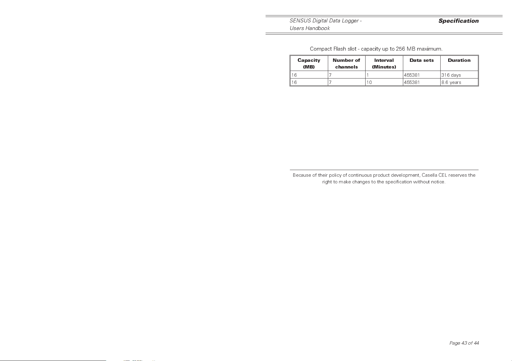
Logging Capacity - External:
Compact Flash slot - capacity up to 256 MB maximum.
Specification
Capacity
(MB)
16 7 1 455381 316 days
16 7 10 455381 8.6 years
Because of their policy of continuous product development, Casella CEL reserves the
Number of
channels
right to make changes to the specification without notice.
Interval
(Minutes)
Data sets Duration
Page 43 of 44

Specification
SENSUS Digital Data Logger -
Users Handbook
Page44of44
 Loading...