

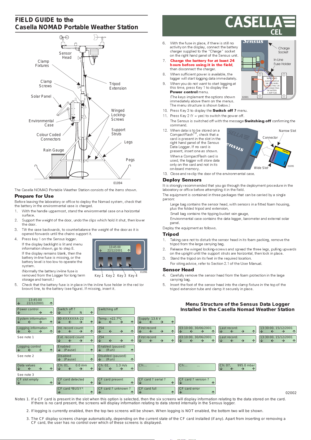
FIELD GUIDE to the
N
Casella NOMAD Portable Weather Station
Sensor
Clamp
Fixtures
Clamp
Screws
Solar Panel
Environmental
Case
Colour Coded
Connectors
Rain Gauge
The Casella NOMAD Portable Weather Station consists of the items shown.
Prepare for Use
Before leaving the laboratory or office to deploy the Nomad system, check that
the battery in the environmental case is charged.
1. With the handle uppermost, stand the environmental case on a horizontal
surface.
2. Support the weight of the door, undo the clips which hold it shut, then lower
the door.
3. Tilt the case backwards, to counterbalance the weight of the door as it is
opened forwards until the chains support it.
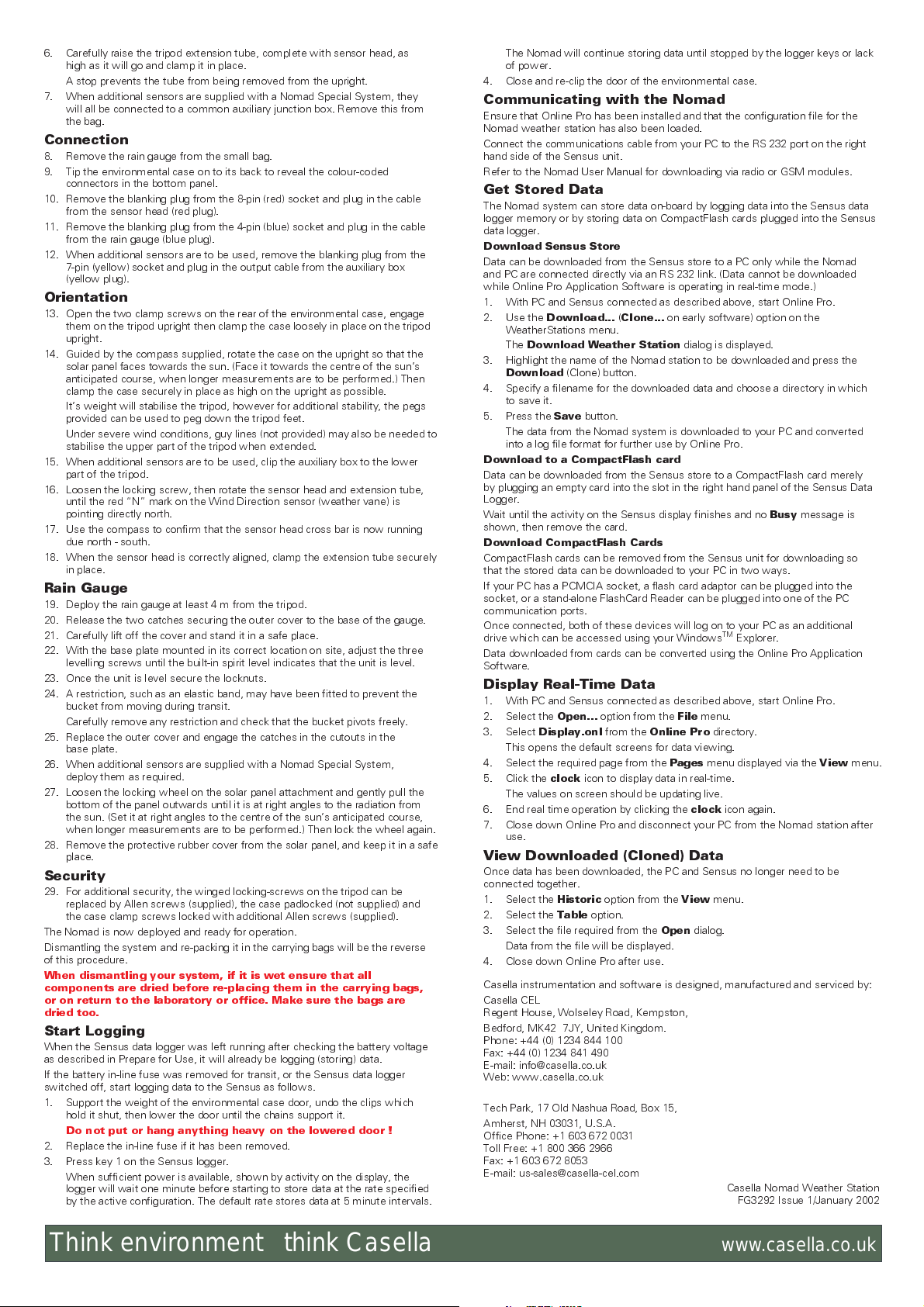
4. Press key 1 on the Sensus logger.
If the display backlight is lit and menu
information shown, go to step 8.
If the display remains blank, then the
battery in-line fuse is missing, or the
battery level is too low to operate the
system.
(Normally the battery in-line fuse is
removed from the Logger for long term
storage and transit.)
5. Check that the battery fuse is in place in the in-line fuse holder in the red (or
brown) line, to the battery (see figure). If missing, insert it.
Head
Tripod
Extension
Winged
LockingScrews
Support
Struts
Legs
Pegs
01094
13:45:00
22/12/2001
Key 1 Key 2 Key 3 Key 4
01096
6. With the fuse in place, if there is still no
activity on the display, connect the battery
charger supplied to the Charge socket
on the right hand panel of the Sensus unit.
7.
Charge the battery for at least 24
hours before using it in the field
then disconnect the charger.
8. When sufficient power is available, the
logger will start logging data immediately.
9. When you do not want to start logging at
this time, press Key 1 to display the
Power control
(The keys implement the options shown
immediately above them on the menus.
The menu structure is shown below.)
10. Press Key 3 to display the
menu.
Switch off ?
,
02001
menu.
In-Line
Fuse Holder
WARNING
ALWAYS REMOVE
THE FUSE WHEN
CONNECTING OR
DISCONNECTING
THE BATTERY.
1 AMP FUSE
Charge
Socket
11. Press Key 2 (Y = yes) to switch the power off.
The Sensus is switched off with the message
command.
12. When data is to be stored on a
CompactFlash
card is present in the slot in the
right hand panel of the Sensus
Data Logger. If no card is
present, insert one as shown.
When a CompactFlash card is
used, the logger will store data
only on the card and not in its
on-board memory.
TM
, check that a
Switching off
Connector
Wide Slot
confirming the
Narrow Slot
01095
13. Close and re-clip the door of the environmental case.
Deploy Sensors
It is strongly recommended that you go through the deployment procedure in the
laboratory or office before attempting it in the field.
The equipment is contained in three packages that can be carried by a single
person:
Large bag contains the sensor head, with sensors in a fitted foam housing,
plus the folded tripod and extension,
Small bag contains the tipping bucket rain gauge,
Environmental case contains the data logger, barometer and external solar
panel.
Deploy the equipment as follows.
Tripod
1. Taking care not to disturb the sensor head in its foam packing, remove the
tripod from the large carrying bag.
2. Release the winged locking-screws and spread the three legs, pulling upwards
on the upright until the support struts are horizontal, then lock in place.
3. Stand the tripod on its feet in the required location.
For siting advice, refer to Section 2.1 of the User Manual.
Sensor Head
4. Carefully remove the sensor head from the foam protection in the large
carrying bag.
5. Insert the foot of the sensor head into the clamp fixture in the top of the
tripod extension tube and clamp it securely in place.
13:45:00
22/12/2001
Power control
System information
Logging information
See note 1
Logging control
See note 2
Data values
See note 3
CF slot empty
Switch off ?
80-XXXXXXA-22
Int. record count:
Ext. record count:
Enabled
(Pause)
Disabled
(Pause)
Ch: 01,
CF card detected CF card present CF card ?serial ? CF card ? version ?
CF card *BUSY* CF card ? unknown ? CF card full CF card error
N
Y
0.0 mm 1.3m/s ... ... 995.0 mbar
Switching off
Temp.: +22.7 C
254
254
Enabled (paused)
Disabled (paused)
Ch: 02, Ch:... Ch:... Ch: 07,
o
(Run)
(Run)
Supply: 13.6 V
First record
First record
Menu Structure of the Sensus Data Logger
Installed in the Casella Nomad Weather Station
03:10:00, 30/06/2001
03:10:00, 30/06/2001
Last record:
Last record:
13:30:00, 15/12/2001
13:30:00, 15/12/2001
02002
If a CF card is present in the slot when this option is selected, then the six screens will display information relating to the data stored on the card.
otes 1.
If there is no card present, the screens will display information relating to data stored internally in the Sensus logger.
If logging is currently enabled, then the top two screens will be shown. When logging is NOT enabled, the bottom two will be shown.
2.
The CF display screens change automatically, depending on the current state of the CF card installed (if any). Apart from inserting or removing a
3.
CF card, the user has no control over which of these screens is displayed.
6. Carefully raise the tripod extension tube, complete with sensor head, as
high as it will go and clamp it in place.
A stop prevents the tube from being removed from the upright.
7. When additional sensors are supplied with a Nomad Special System, they
will all be connected to a common auxiliary junction box. Remove this from
the bag.
Connection
8. Remove the rain gauge from the small bag.
9. Tip the environmental case on to its back to reveal the colour-coded
connectors in the bottom panel.
10. Remove the blanking plug from the 8-pin (red) socket and plug in the cable
from the sensor head (red plug).
11. Remove the blanking plug from the 4-pin (blue) socket and plug in the cable
from the rain gauge (blue plug).
12. When additional sensors are to be used, remove the blanking plug from the
7-pin (yellow) socket and plug in the output cable from the auxiliary box
(yellow plug).
Orientation
13. Open the two clamp screws on the rear of the environmental case, engage
them on the tripod upright then clamp the case loosely in place on the tripod
upright.
14. Guided by the compass supplied, rotate the case on the upright so that the
solar panel faces towards the sun. (Face it towards the centre of the suns
anticipated course, when longer measurements are to be performed.) Then
clamp the case securely in place as high on the upright as possible.
Its weight will stabilise the tripod, however for additional stability, the pegs
provided can be used to peg down the tripod feet.
Under severe wind conditions, guy lines (not provided) may also be needed to
stabilise the upper part of the tripod when extended.
15. When additional sensors are to be used, clip the auxiliary box to the lower
part of the tripod.
16. Loosen the locking screw, then rotate the sensor head and extension tube,
until the red N mark on the Wind Direction sensor (weather vane) is
pointing directly north.
17. Use the compass to confirm that the sensor head cross bar is now running
due north - south.
18. When the sensor head is correctly aligned, clamp the extension tube securely
in place.
Rain Gauge
19. Deploy the rain gauge at least 4 m from the tripod.
20. Release the two catches securing the outer cover to the base of the gauge.
21. Carefully lift off the cover and stand it in a safe place.
22. With the base plate mounted in its correct location on site, adjust the three
levelling screws until the built-in spirit level indicates that the unit is level.
23. Once the unit is level secure the locknuts.
24. A restriction, such as an elastic band, may have been fitted to prevent the
bucket from moving during transit.
Carefully remove any restriction and check that the bucket pivots freely.
25. Replace the outer cover and engage the catches in the cutouts in the
base plate.
26. When additional sensors are supplied with a Nomad Special System,
deploy them as required.
27. Loosen the locking wheel on the solar panel attachment and gently pull the
bottom of the panel outwards until it is at right angles to the radiation from
the sun. (Set it at right angles to the centre of the suns anticipated course,
when longer measurements are to be performed.) Then lock the wheel again.
28. Remove the protective rubber cover from the solar panel, and keep it in a safe
place.
Security
29. For additional security, the winged locking-screws on the tripod can be
replaced by Allen screws (supplied), the case padlocked (not supplied) and
the case clamp screws locked with additional Allen screws (supplied).
The Nomad is now deployed and ready for operation.
Dismantling the system and re-packing it in the carrying bags will be the reverse
of this procedure.
When dismantling your system, if it is wet ensure that all
components are dried before re-placing them in the carrying bags,
or on return to the laboratory or office. Make sure the bags are
dried too.
Start Logging
When the Sensus data logger was left running after checking the battery voltage
as described in Prepare for Use, it will already be logging (storing) data.
If the battery in-line fuse was removed for transit, or the Sensus data logger
switched off, start logging data to the Sensus as follows.
1. Support the weight of the environmental case door, undo the clips which
hold it shut, then lower the door until the chains support it.
Do not put or hang anything heavy on the lowered door !
2. Replace the in-line fuse if it has been removed.
3. Press key 1 on the Sensus logger.
When sufficient power is available, shown by activity on the display, the
logger will wait one minute before starting to store data at the rate specified
by the active configuration. The default rate stores data at 5 minute intervals.
The Nomad will continue storing data until stopped by the logger keys or lack
of power.
4. Close and re-clip the door of the environmental case.
Communicating with the Nomad
Ensure that Online Pro has been installed and that the configuration file for the
Nomad weather station has also been loaded.
Connect the communications cable from your PC to the RS 232 port on the right
hand side of the Sensus unit.
Refer to the Nomad User Manual for downloading via radio or GSM modules.
Get Stored Data
The Nomad system can store data on-board by logging data into the Sensus data
logger memory or by storing data on CompactFlash cards plugged into the Sensus
data logger.
Download Sensus Store
Data can be downloaded from the Sensus store to a PC only while the Nomad
and PC are connected directly via an RS 232 link. (Data cannot be downloaded
while Online Pro Application Software is operating in real-time mode.)
1. With PC and Sensus connected as described above, start Online Pro.
2. Use the
3. Highlight the name of the Nomad station to be downloaded and press the
4. Specify a filename for the downloaded data and choose a directory in which
5. Press the
Download to a CompactFlash card
Data can be downloaded from the Sensus store to a CompactFlash card merely
by plugging an empty card into the slot in the right hand panel of the Sensus Data
Logger.
Wait until the activity on the Sensus display finishes and no
shown, then remove the card.
Download CompactFlash Cards
CompactFlash cards can be removed from the Sensus unit for downloading so
that the stored data can be downloaded to your PC in two ways.
If your PC has a PCMCIA socket, a flash card adaptor can be plugged into the
socket, or a stand-alone FlashCard Reader can be plugged into one of the PC
communication ports.
Once connected, both of these devices will log on to your PC as an additional
drive which can be accessed using your Windows
Data downloaded from cards can be converted using the Online Pro Application
Software.
Download...(Clone...
WeatherStations menu.
The
Download Weather Station
Download
to save it.
The data from the Nomad system is downloaded to your PC and converted
into a log file format for further use by Online Pro.
(Clone) button.
Save
button.
on early software) option on the
dialog is displayed.
Busy
message is
TM
Explorer.
Display Real-Time Data
1. With PC and Sensus connected as described above, start Online Pro.
2. Select the
3. Select
This opens the default screens for data viewing.
4. Select the required page from the
5. Click the
The values on screen should be updating live.
6. End real time operation by clicking the
7. Close down Online Pro and disconnect your PC from the Nomad station after
use.
Open...
option from the
Display.onl
clock
from the
icon to display data in real-time.
File
Online Pro
Pages
clock
menu.
directory.
menu displayed via the
icon again.
View
menu.
View Downloaded (Cloned) Data
Once data has been downloaded, the PC and Sensus no longer need to be
connected together.
1. Select the
2. Select the
3. Select the file required from the
Data from the file will be displayed.
4. Close down Online Pro after use.
Casella instrumentation and software is designed, manufactured and serviced by:
Casella CEL
Regent House, Wolseley Road, Kempston,
Bedford, MK42 7JY, United Kingdom.
Phone: +44 (0) 1234 844 100
Fax: +44 (0) 1234 841 490
E-mail: info@casella.co.uk
Web: www.casella.co.uk
Tech Park, 17 Old Nashua Road, Box 15,
Amherst, NH 03031, U.S.A.
Office Phone: +1 603 672 0031
Toll Free: +1 800 366 2966
Fax: +1 603 672 8053
E-mail: us-sales@casella-cel.com
Historic
Table
option from the
option.
Open
View
menu.
dialog.
Casella Nomad Weather Station
FG3292 Issue 1/January 2002
Think environment think Casella
www.casella.co.uk
 Loading...