


NOMAD Portable Weather Station
Users Handbook
Portable Weather Station
May 2002
NOMAD
Users Handbook
HB3289-01
COPYRIGHT
The copyright in this document which contains proprietary information is vested in
CASELLA CEL. The contents of this document must not be used for
purposes other than for which it has been supplied or reproduced or disclosed wholly
or in part without the prior written permission of
CASELLA CEL
CASELLA CEL
Regent House
Wolseley Road
Kempston
Bedford
MK42 7JY U.K.
Phone: +44 (0)1234 844100
Fax: +44 (0)1234 841490
E-Mail: info@casellagroup.com
Web: www.casellagroup.com
CASELLA USA
17 Old Nashua Road #15
Amherst
NH 03031
U.S.A.
Toll Free: +1 800 366 2966
Fax: +1 603 672 8053
E-mail: info@casellausa.com
Web: www.casellausa.com

Contents
NOMAD Portable Weather Station
Users Handbook
Page 2 of 68

NOMAD Portable Weather Station
Users Handbook
WARNINGS !
The Nomad Weather Station is not intended for projects that
extend for durations longer than six months, without
maintenance.
Warnings
Page 3 of 68

Warnings
NOMAD Portable Weather Station
Users Handbook
Page 4 of 68

NOMAD Portable Weather Station
Users Handbook
Contents . . . . . . . . . . . . . . . . . . . . Page
1. INTRODUCTION TO THE NOMAD ................ 7
1.1 Three Versions .................... 7
1.2 Features and Applications ............... 7
2. COMMISSIONING . ...................... 9
2.1 ScheduleofParts ................... 9
2.2 Siting . . ......................10
2.3 Preparing for Use . . . ................10
2.4 DeployingtheSensors.................11
3. OPERATION USING A DIRECT LINK BETWEEN PC AND NOMAD, VIA
FLASH CARDS, CABLE, GSM MODEM, OR HIGH POWER RADIO . . 15
3.1 StartLogging .....................15
3.2 Get Stored Data ....................15
3.2.1 Download Sensus Store . . ..........16
3.2.2 Download to a CompactFlash Card . . . ....16
3.2.3 Download CompactFlash Cards .........16
3.3 Read Data from the Sensus Display . ..........16
3.4 Display Real-Time Data ................17
3.5 View Downloaded (Cloned) Data . . ..........18
4. OPERATION USING A PASSIVE RADIO LINK BETWEEN PC
ANDNOMAD .........................19
4.1 StartLogging .....................19
4.2 Display Real-Time Data ................19
4.3 View Downloaded (Cloned) Data . . ..........20
5 ONLINE PRO APPLICATION SOFTWARE . . . ..........21
5.1 Introduction to Online Pro, Version 1.2 .........21
5.2 Installation / Un-Installation on Windows
ME, NT 4 & 2000 . . . ................22
5.2.1 Installation . . ................23
5.2.2 Un-Installation . ................23
5.2.3 Starting Online Pro for the First Time . . ....23
5.2.4 Password Protection ..............24
5.2.5 Loading a Default File . . . ..........24
5.3 Operation in Real-Time ................25
5.3.1 Viewing Pages and Operating in Real-Time . . . 26
5.3.2 Setting Up Pages ................28
5.3.3 Adding Real Time Display Items ........29
5.3.4 Saving the Display File . . . ..........33
5.3.5 Web Page Output ...............34
5.4 WorkingwithHistoricData...............35
5.4.1 Downloading (Cloning) Data ..........35
5.4.2 Downloading from CompactFlash
5.4.3 Converting Online and CompactFlash Files ....36
5.4.4 Viewing Historic Data . . . ...........37
5.5 DynamicDataExchange................40
6. THE NOMAD SYSTEM COMPONENTS ..............41
6.1 The Sensors Used with Nomad Systems .........41
6.2 Combined Air Temperature and Relative Humidity Sensor 42
6.2.1 Temperature Sensor Specification ........42
6.2.2 Humidity Sensor Specification .........42
6.2.3 General Specification ..............43
6.3 WindSpeedSensor ..................43
TM
95, 98,
TM
Cards....36
Contents
Page 5 of 68

Contents
NOMAD Portable Weather Station
Contents . . . . . . . . . . . . . . . . . . . . Page
6.3.1 Wind Speed Sensor Specification ........43
6.4 Wind Direction Sensor . ................43
6.4.1 Wind Direction Sensor Specification . . . ....44
6.5 Global Solar Radiation Sensor . . . ..........44
6.5.1 Global Solar Radiation Sensor Specification . . . 45
6.5.2 Sunshine Duration ...............45
6.6 Barometric Pressure Sensor ..............45
6.6.1 Barometric Pressure Sensor Specification ....45
6.7 Rainfall Sensor ....................45
6.7.1 Rainfall Sensor Specification ..........46
6.8 Soil Temperature Sensor ................46
6.8.1 Soil Temperature Sensor Specification . . ....46
6.9 Leaf Wetness Sensor . . ................47
6.9.1 Leaf Wetness Sensor Specification . . . ....47
6.10 Grass Temperature Sensor ...............47
6.10.1 Grass Temperature Sensor Specification . ....48
7, THE SENSUS DIGITAL DATA LOGGER ..............49
7.1 Brief Introduction to the Sensus Data Logger . . ....49
7.2 Commands ......................50
7.3 Logging........................50
7.3.1 Internal Capacity ...............50
7.3.2 External Capacity ...............51
7.4 Input Connections . . . ................52
7.4.1 Wire Preparation and Insertion .........52
7.4.2 Standard Sensus Settings for Nomad Systems . . 52
7.5 Sensus Communications ................53
7.5.1 RS 232 Command ...............53
7.5.2 Sleep mode . . ................54
7.5.3 Display ....................54
7.6 CompactFlash
8. COMMUNICATION . ......................57
8.1 Direct Cable Link . . . ................58
8.2 CompactFlash Cards . . ................58
8.3 HighPowerRadioLink.................58
8.3.1 High Power Radio Transmitter Specification . . . 58
8.3.2 High Power Radio Modem Specification . ....59
8.3.3 High Power Radio General Specification . ....59
8.3.4 High Power Radio LED Indicators ........59
8.3.5 High Power Radio Standard Settings . . ....59
8.4 Low Power Radio Link . ................59
8.4.1 Low Power Radio Transmitter Specification . . . 60
8.4.2 Low Power Radio Receiver Specification . ....61
8.5 GSM Link . ......................61
9. POWERSUPPLIES.......................63
9.1 SolarPower......................63
9.2 Battery . . ......................63
9.3 Direct Landline Connection ...............63
10. ROUTINECARE ........................65
1.1 General........................65
1.2 TheRainGauge....................65
11. SERVICING & WARRANTY . . . ................67
TM
Cards.................54
Users Handbook
Page 6 of 68

NOMAD Portable Weather Station
Users Handbook
Introduction
1. INTRODUCTION TO THE NOMAD
The Nomad Portable Weather Station designed and manufactured by Casella
CEL, is a truly portable monitoring station. With a total weight of around 13 kg
(36.5 lb), the station is specifically designed for ease of transportation, rapid
deployment and quality of measurement. It is supplied in two customised carry
bags plus a separate weather-proof case, all of which can be carried together by
one person when necessary.
Nomad is intended to satisfy YOUR professional monitoring needs.
Once on site, the Nomad can be deployed and collecting data in less
than five minutes. Disassembly and re-packing is just as quick, allowing you to
be packed and on-route to the next monitoring location without delay.
Quality construction and an integrated solar-panel gives Nomad the
independence required for prolonged operation in isolated or inhospitable
environments.
Due to the worldwide increase in environmental legislation, many
industrial activities, including construction, demolition and land remediation now
have new requirements to monitor local meteorological conditions. The
environmental conditions impact on many other areas, including agrochemical
research, ecological projects, recreational and sporting activities.
The Nomad’s portability allows the user to monitor any location and as
standard measures: temperature, humidity, pressure, wind speed, wind
direction, solar radiation and rainfall
1.1 Three Versions
Three versions of the Nomad are available.
Standard System Sensors to measure:
Air temperature,
Relative humidity,
Wind speed,
Wind direction,
Solar radiation,
Barometric pressure,
Rainfall (a separate unit).
Wind System Sensors to measure:
Wind speed,
Wind direction,
Barometric pressure.
Special System All of the sensors used in the standard
system, plus up to four further sensors to
measure:
Soil temperature,
Leaf wetness,
Grass minimum temperatures.
1.2 Features and Applications
The Nomad has the following main features.
¤ Portable and lightweight construction to allow rapid system deployment
¤ High quality anodised aluminium and stainless components
¤ Latest logging technology records approximately 15 k data sets as
standard
¤ Compact Flash Expansion Slot for prolonged monitoring applications
¤ Integrated solar-panel/charger allows extended operation
Page 7 of 68

Introduction
¤ Pre-configured 32-bit Online Pro PC software, for real-time and
historic data analysis
¤ Protective carry bags for ease of transport
¤ Quality external connectors to IP68
¤ Telemetry options include: RS232, RS485, low power radio or global
access using GSM modem
Potential applications are monitoring and checking, as follows.
¤ Environmental consultancy
¤ Site boundaries
¤ Landfill sites
¤ Emergency services
¤ Military operations
¤ Conditions at ports and harbours
¤ Airports gliding clubs
¤ Agrochemical field trials
¤ Fruit growing
¤ Hydrological studies
¤ Schools & colleges for field studies
¤ Geotechnical studies
¤ Golf courses
¤ Athletics meetings
NOMAD Portable Weather Station
Users Handbook
Page 8 of 68

NOMAD Portable Weather Station
Users Handbook
2. COMMISSIONING
2.1 Schedule of Parts
The Nomad Portable Weather System consists of the following items.
Sensus data logger (installed in environmental case)
Tripod
Internal lead acid battery
Solar panel
Aerial sensor array with sensors for:
Air temperature
Relative humidity
Wind speed
Wind direction
Solar radiation
Barometric pressure sensor, integral to the data logger
Tipping bucket rain gauge (0.2 mm), separate unit with 9 m cable
Anchoring kit, with tools and compass
Large transit bag for tripod plus sensors
Smaller transit bag for raingauge
Online Pro PC Application Software and download cable
Commissioning
The Nomad Wind System consists of the following items.
Sensus data logger (installed in environmental case)
Tripod
Internal lead acid battery
Solar panel
Aerial sensor array with sensors for:
Wind speed
Wind direction
Barometric pressure sensor, integral to the data logger
Anchoring kit, with tools and compass
Large transit bag for tripod plus sensors
Online Pro PC Application Software and download cable
The Special Nomad Monitoring Systems are defined as any that requires some
other combination of sensors, such as the following items.
Sensus data logger (installed in environmental case)
Tripod
Internal lead acid battery
Solar panel
Aerial sensor array with sensors for:
Air temperature
Relative humidity
Wind speed
Wind direction
Solar radiation
Barometric pressure sensor integral to the data logger
Tipping bucket rain gauge (0.2 mm), separate unit with 9 m cable
Soil temperature sensor
Leaf wetness sensor
Grass minimum temperature sensor
Anchoring Kit, with tools and compass
Large transit bag for tripod plus sensors
Smaller transit bag for raingauge
Online Pro PC Application Software and download cable
Page 9 of 68
Commissioning
Check that all of the components have been delivered.
NOMAD Portable Weather Station
2.2 Siting
The measurements used in meteorology are intended to represent general
conditions over as large an area around the measuring point as possible.
To achieve the most representative local conditions, the Nomad should
be sited in an unobstructed area open to the sun and wind. This also maximises
the efficiency of the solar-panel power supply. Sites sheltered by trees or
buildings, in hollows or on the sides of hills are not recommended, neither are
sites on buildings, as none of these locations will give representative
measurements.
The Nomad Portable Weather Station is designed to meet these
conditions. It’s sensors are mounted on a cross-bar 2.0 m above the ground.
Undere severe wind conditions, using guy ropes or attaching sand bags will offer
additional stability.
The U.K. Meteorological Office (Met Office) recommends that the
instruments be installed over closely mown grass. For further guidance, refer to
the Met Office leaflets:
Making weather observations,
Manual weather measurements,
Automatic weather measurements,
Voluntary observations network.
Users Handbook
2.3 Preparing for Use
Before leaving the laboratory or office to deploy the Nomad system, check that
the battery in the environmental case is charged.
1. With the handle uppermost, stand the environmental case on a
horizontal surface.
2. Support the weight of the door, undo the clips which hold it shut, then
lower the door.
3. Tilt the case backwards, to counterbalance the weight of the door as it
is opened forwards until the chains support it.
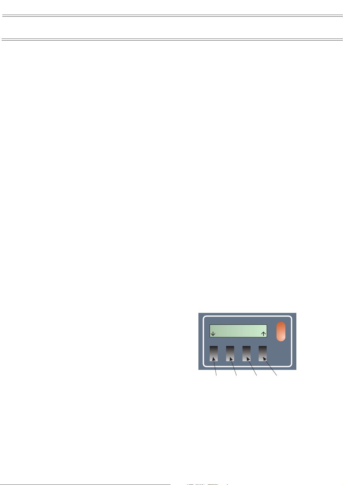
4. Press key 1 on the Sensus logger (Figure 1).
If the display backlight is lit and menu
information shown, go to step 8.
If the display remains blank, then the
battery in-line fuse is missing, or the
battery level is too low to operate the
system.
(Normally the battery in-line fuse is
removed from the Logger for long
term storage and transit.)
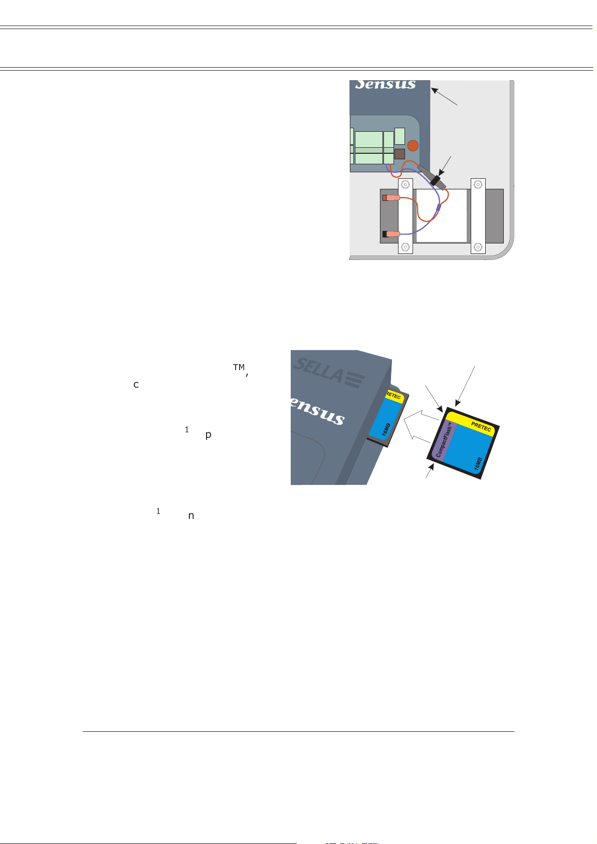
5. Check that the battery fuse is in place
in the in-line fuse holder in the red
(or brown) line, to the battery
(Figure 2). If missing, insert it.
Key 1 Key 2 Key 3 Key 4
Figure 1: Sensus logger - display
13:45:00
22/12/2001
01096
and keys
6. With the fuse in place, if there is still
no activity on the display, connect the battery charger supplied to the
“Charge” socket on the right hand panel of the Sensus unit.
Page 10 of 68
NOMAD Portable Weather Station
Users Handbook
7. Charge the battery for at least 24
hours before using it in the field,
then disconnect the charger.
8. When sufficient power is available,
the logger will start logging data
immediately.
9. When you do not want to start logging
at this time, press Key 1 to display the
Power control menu.
(The keys implement the options
shown immediately above them on the
menus. The menu structure is shown
in Figure 6.)
02001
Commissioning
Charge
Socket
In-Line
Fuse Holder
WARNING
ALWAYS REMOVE
THE FUSE WHEN
CONNECTING OR
DISCONNECTING
THE BATTERY.
1 AMP FUSE
10. Press Key 3 to display the Switch off ?
menu.
Figure 2: Location of the Charge
socket and in-line fuse
11. Press Key 2 (Y = yes) to switch the power off.
The Sensus is switched off with the message Switching off confirming
the command.
12. When data is to be stored
on a CompactFlash
TM
,
check that a card is
Connector
Narrow Slot
present in the slot in the
right hand panel of the
Sensus Data Logger.
If no card
1
is present,
insert one as shown in
Figure 3.
When a CompactFlash card
is used, the logger will
store data only on the
1
card
and not in its on-board memory. (Also see Section 4.8.)
Figure 3: Installing a CompactFlash card
Wide Slot
2.4 Deploying the Sensors
The equipment is contained in three packages that can be carried by a single
person.
01095
Large Bag (1050 x 300 mm footprint) with shoulder strap that contains
the sensor head, complete with sensors, inverted in a fitted foam
housing plus the folded tripod and extension post,
Small Bag (300 x 300 mm footprint) with handles that contains the
tipping bucket rain gauge,
Environmental Case (polypropylene) with handle that contains the data
logger, barometer and the external solar panel.
The Nomad can be deployed and logging data within five minutes. However, it is
strongly recommended that you run through the installation procedure in the
Note 1: A CompactFlash card which has already stored or download data, cannot function with
a measuring station that has a different configuration from the last used station.
Therefore, either clear the card before starting operations with a different station, or
select only a card that has previously been used with the same station.
Page 11 of 68
Commissioning
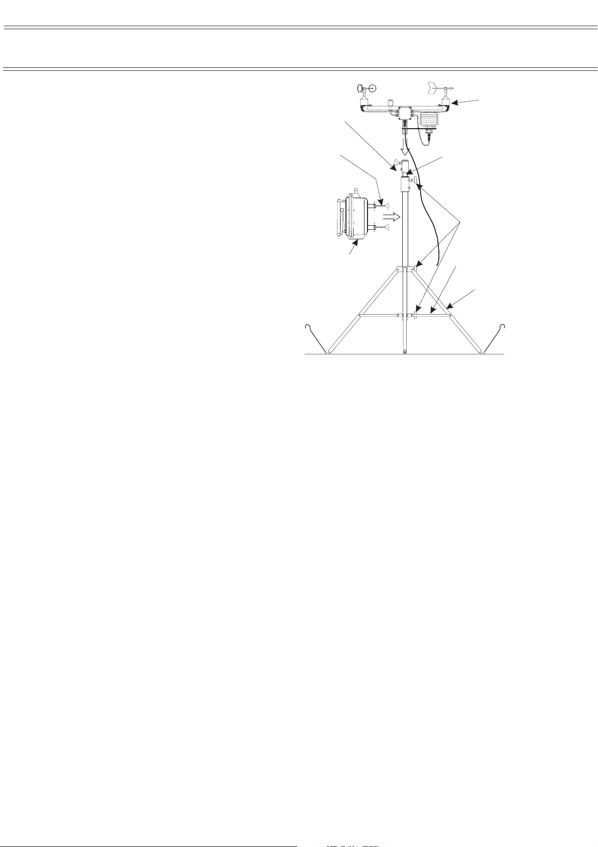
S
laboratory or office before attempting it
in the field. Referring to Figure 4,
deploy the equipment as follows.
Tripod
1. Taking care not to disturb the
sensor head in its foam
packing, remove the tripod
from the large carrying bag.
Clamp
Fixtures
Clamp
crews
NOMAD Portable Weather Station
Users Handbook
"N"
Sensor
Head
Tripod
Extension
2. Release the winged lockingscrews and spread the three
legs, pulling upwards on the
upright until the support
struts are horizontal, then
lock in place.
3. Stand the tripod on its feet in
the required location.
For siting advice, refer to
Section 2.1.
Sensor Head
4. Carefully remove the sensor
head from the foam protection
in the large carrying bag.
5. Insert the foot of the sensor head into the clamp fixture in the top of
the tripod extension tube and clamp it securely in place.
6. Carefully raise the tripod extension tube, complete with sensor head, as
high as it will go and clamp it in place.
A stop prevents the tube from being removed from the upright.
Env.
Case
Colour
Coded
Connectors
Figure 4: Deploying the tripod and
sensor head
Winged
LockingScrews
Support
Struts
Legs
Pegs
01054
7. When additional sensors are supplied with a Nomad Special System,
they will all be connected to a common auxiliary junction box. Remove
this from the bag.
Connection
8. Remove the rain gauge from the small bag.
9. Tip the environmental case on to its back to reveal the colour-coded
connectors in the bottom panel.
10. Remove the blanking plug from the 8-pin (red) socket and plug in the
cable from the sensor head (red plug).
11. Remove the blanking plug from the 4-pin (blue) socket and plug in the
cable from the rain gauge (blue plug).
12. When additional sensors are to be used, remove the blanking plug from
the 7-pin (yellow) socket and plug in the output cable from the
auxiliary box (yellow plug).
13. Open the two clamp screws on the rear of the environmental case,
engage them on the tripod upright then clamp the case loosly in place
on the tripod upright.
Page 12 of 68

NOMAD Portable Weather Station
Users Handbook
Commissioning
Orientation
14. Guided by the compass supplied, rotate the case on the upright so that
the solar panel faces towards the sun. (Face it towards the centre of
the sun’s anticipated course, when longer measurements are to be
performed.) Then clamp the case securely in place as high on the
upright as possible.
It’s weight will stabilise the tripod, however for additional stability, the
pegs provided can be used to peg down the tripod feet.
Under severe wind conditions, guy lines (not provided) may also be
needed to stabilise the upper part of the tripod when extended.
15. When additional sensors are to be used, clip the auxiliary box to the
lower part of the tripod.
16. Loosen the locking screw, then rotate the sensor head and extension
tube, until the red “N” mark on the Wind Direction sensor (weather
vane) is pointing directly north.
17. Use the compass to confirm that the sensor head cross bar is now
running due north - south.
18. When the sensor head is correctly aligned, clamp the extension tube
securely in place.
Rain Gauge
19. Deploy the rain gauge at least 4 m from the tripod.
20. Release the two catches securing the outer cover to the base of the rain
gauge.
21. Carefully lift off the cover and stand it in a safe place.
22. With the base plate mounted in its correct location on site, adjust the
three levelling screws until the built-in spirit level indicates that the
unit is level.
23. Once the unit is level secure the locknuts.
24. A restriction, such as an elastic band, may have been fitted to prevent
the bucket from moving during transit.
Carefully remove any restriction
and check that the bucket pivots
freely.
25. Replace the outer cover and
engage the catches in the cutouts
in the base plate.
Sun
Rays
Right
Angle
26. When additional sensors are
supplied with a Nomad Special
System, deploy them as required.
27. Loosen the locking wheel on the
solar panel attachment and gently
pull the bottom of the panel
outwards until it is at right angles
to the radiation from the sun as
shown in Figure 5.
Locking
Wheel
Aux.
Junction
Box
01055
Figure 5: Adjusting the solar panel
Page 13 of 68

Commissioning
(Set it at right angles to the centre of the sun’s anticipated course,
when longer measurements are to be performed.) Then lock the wheel
again.
28. Remove the protective cover from
the solar panel, and keep it in a safe place.
NOMAD Portable Weather Station
Security
29. For additional security, the winged
locking-screws on the tripod can be replaced by Allen screws
(supplied), the case padlocked (not supplied) and the case clamp
screws locked with additional Allen screws (supplied).
The Nomad is now deployed and ready for operation.
Dismantling the system and re-packing it in the carrying bags will be
the reverse of this procedure. Make sure the cover is replaced on the solar
panel, and the locking wheel is tightened to prevent the panel moving in transit.
When dismantling your system, if it is wet ensure that all
components are dried before re-placing them in the carrying bags, or on
return to the laboratory or office. Make sure the bags are dried too.
Users Handbook
Page 14 of 68

NOMAD Portable Weather Station
Users Handbook
Operation via Direct Link
3. OPERATION USING A DIRECT LINK BETWEEN
PC AND NOMAD, VIA FLASHCARDS, CABLE,
GSM MODEM, OR HIGH POWER RADIO
The procedures described in this chapter may be used with any Nomad system
that is connected to the PC by RS 232 cable, connected via a GSM (Global
System for Mobile communications) modem, or connected via a high power
radio link
Nomad system in the field, or a permanently connected system.
Chapter 2. When full communication via a high power radio link is required,
supply 24 V DC to the Nomad station. For example use the standard W4/1602/4
Cable (500 m) and 142009C Landline Interface mentioned in Section 9.3.
data logger, the user can visit the System to download data, data can be
downloaded via a permanent RS 232 cable link (when one exists), or
downloaded over a GSM modem or high power radio link with landline power.
configuration file for the Nomad weather station has also been loaded (see
Chapter 5).
cable from your PC to the RS 232 port on the right hand side of the Sensus unit.
2
. Cable connection may be temporary when a technician is visiting any
Assemble the system and deploy the sensors as described in
Once the Nomad system has stored the required data in the Sensus
Ensure that Online Pro has been installed on the PC and that the
When visiting the Nomad for download, connect the communications
See Chapter 8 for a review of the available communication methods.
3.1 Start Logging
When the Sensus data logger was left running after checking the battery voltage
as described in Section 2.3, it will already be logging (storing) data.
If the battery in-line fuse was removed for transit, or the Sensus data
logger switched off, start logging data to the Sensus as follows.
1. Support the weight of the environmental case door, undo the clips
which hold it shut, then lower the door until the chains support it.
Do not put or hang anything heavy on the lowered door !
2. Replace the in-line fuse if it has been removed.
3. Press key 1 on the Sensus logger (shown in Figure 1).
When sufficient power is available, shown by activity on the display,
the logger will wait one minute before starting to store data at the rate
specified by the active configuration. The default rate stores data at 5
minute intervals.
The Nomad will continue storing data until stopped by the logger keys
or lack of power.
4. Close and re-clip the door of the environmental case.
3.2 Get Stored Data
The Nomad system can store data on-board by logging data into the Sensus
data logger memory or by storing data on CompactFlash cards plugged into the
Sensus data logger.
Note 2: Because of power constraints, when the Nomad system is powered by the solar panel
and internal battery, it is configured to operate as a semi-passive data transmission
system in the same way as the low power radio link. See chapter 4.
Configuration for full two-way operation with a high power radio link, as described in
this chapter, is possible ONLY when the Nomad system receives its power from a
landline.
Page 15 of 68

Operation via Direct Link
NOMAD Portable Weather Station
3.2.1 Download Sensus Store
Data can be downloaded from the Sensus store to a PC only while the Nomad
and PC are connected directly via an RS 232 cable link landline interface, a GSM
modem link, or a high power radio link with landline power.
Data cannot be downloaded while the Online Pro Application
Software is operating in real-time mode, (or connected via a low power
radio link).
1. With PC and Sensus connected as described above, start Online Pro.
2. Use the Download... (Clone... on early software) option on the
WeatherStations menu.
The Download Weather Station dialog is displayed.
3. Highlight the name of the Nomad station to be downloaded and press
the Download (Clone) button.
(When the Nomad is connected via a GSM modem or high power radio
link, Online Pro will call the relevant system automatically.)
4. Specify a filename for the downloaded data and choose a directory in
which to save it.
Users Handbook
5. Press the Save button.
The data from the Nomad system is downloaded to your PC and
converted into a log file format for further use by Online Pro.
3.2.2 Download to a CompactFlash Card
When visiting the Nomad, data can be downloaded from the Sensus store to a
CompactFlash card merely by plugging an empty
hand panel of the Sensus Data Logger. Wait until the activity on the Sensus
display finishes then remove the card.
3
card into the slot in the right
3.2.3 Download CompactFlash Cards
CompactFlash cards can be removed from the Sensus unit for downloading so
that the stored data can be downloaded to your PC in two ways.
If the PC has a PCMCIA socket, a flash card adaptor can be plugged
into the socket. Alternatively a stand-alone FlashCard Reader can be plugged
into one of the PC communication ports.
Once connected, both of these devices will log on to your PC as an
additional drive which can be accessed using Windows
Data downloaded from cards must be converted for use with Online
Pro Application Software.
TM
Explorer.
3.3 Read Data from the Sensus Display
When visiting the measuring station, the display keys on the Sensus Data
Logger can be used to show data (and other information) on the display.
1. Press key 1 (see Figure 1).
The first screen of the Sensus menu system will be displayed. This is
shown at the top left of the menu structure diagram in Figure 6.
Note 3: A CompactFlash card which has already stored or download data, cannot function with
a measuring station that has a different configuration from the last used station.
Therefore, either clear the card before starting operations with a different station, or
select only a card that has previously been used with the same station.
Page 16 of 68

N
NOMAD Portable Weather Station
Users Handbook
13:45:00
22/12/2001
Power control
System information
Switch off ?
Y
N
80-XXXXXXA-22
Switching off
Temp.: +22.7 C
Operation via Direct Link
o
Supply: 13.6 V
Logging information
See Note A
Logging control
See Note B
Data values
See Note C
CF slot empty
If a CF card is present in the slot when this option is selected, then the six screens will display information relating to the
otes A.
data stored on the card. If there is no card present, the screens will display information relating to data stored internally in the
Sensus logger.
If logging is currently enabled, then the top two screens will be shown. When logging is NOT enabled, the bottom two will be
B.
shown.
The CF display screens change automatically, depending on the current state of the CF card installed (if any). Apart from
C.
inserting or removing a CF card, the user has no control over which of these screens is displayed.
Int. record count:
Ext. record count:
Enabled
(Pause)
Disabled
(Pause)
Ch: 01,
CF card detected CF card present CF card ? serial ? CF card ? version ?
CF card *BUSY* CF card ? unknown ? CF card full CF card error
0.0 mm 1.3m/s ... ... 995.0 mbar
254
254
Enabled (paused)
(Run)
Disabled (paused)
(Run)
Ch: 02, Ch:... Ch:... Ch: 07,
First record
First record
03:10:00, 30/06/2001
03:10:00, 30/06/2001
Last record:
Last record:
13:30:00, 15/12/2001
13:30:00, 15/12/2001
Figure 6: Menu structure of the Sensus Data Logger installed in
Nomad Weather Stations
The keys implement the options shown immediately above them on the
menus. The arrow options move the display to adjacent menus in the
indicated direction.
02004
2. Use the down arrow options to move to the Logging information
menu.
3. Use right and left arrow options to check the number of data records
(samples) stored and to inspect the the first and last records.
4. Inspect further information from the Sensus by using the required
options to move about the menu system.
5. The display may safely be left active when you have finished inspecting
information, as the Sensus will switch the display off automatically
after one minute when it detects no further key activity.
3.4 Display Real-Time Data
1. With PC and Sensus connected via an RS 232 cable, GSM modem, or
high power radio with landline power, start Online Pro.
2. Select the Open... option from the File menu.
3. Select Display.onl from the Online Pro directory.
This opens the default screens for data viewing.
4. Select the required page from the Pages menu displayed via the View
menu.
5. Click the clock icon to display data in real-time.
The values on screen should be updating live.
Page 17 of 68

Operation via Direct Link
Remember that if you are using a system connected via a GSM
modem, displaying data in real-time for periods of more than a
few minutes may incur high call charges.
6. End real time operation by clicking the clock icon again.
7. Disconnect your PC from the Nomad station after use.
NOMAD Portable Weather Station
3.5 View Downloaded (Cloned) Data
Once the data has been downloaded, it is no longer necessary to have the PC
and Sensus connected together while viewing downloaded data.
1. Select the Historic option from the View menu.
2. Select the Table option.
3. Select the file required from the Open dialog.
Data from the file will be displayed.
4. Close down Online Pro after use.
Users Handbook
Page 18 of 68

NOMAD Portable Weather Station
Users Handbook
Operation via Passive Radio Link
4. OPERATION USING A PASSIVE RADIO
LINK BETWEEN PC AND NOMAD
The procedures described in this chapter may be used only with Nomad systems
that are connected to the PC by low power radio link or by a high power radio
link configured for transmission only
These links are semi-passive systems that transmit data but cannot be
controlled by the PC. Once the Nomad system is storing the required data in the
Sensus data logger, these links will also be transmitting data every 20 seconds
to the radio link on the PC.
When a technician is visiting the Nomad to download the memory in
the field, use the procedures given in Chapter 3.
Assemble the system and deploy the sensors as described in
Chapter 2. Ensure that Online Pro has been installed on the PC and that the
configuration file for the Nomad weather station has also been loaded (see
Chapter 5).
See Chapter 8 for a review of available communication methods.
4
.
4.1 Start Logging
When the Sensus data logger was left running after checking the battery voltage
as described in Section 2.3, it will already be logging (storing) data and the
radio transmitting it.
If the battery in-line fuse was removed for transit, or the Sensus data
logger switched off, start logging data to the Sensus as follows.
1. Support the weight of the environmental case door, undo the clips
which hold it shut, then lower the door until the chains support it.
Do not put or hang anything heavy on the lowered door !
2. Replace the in-line fuse if it has been removed.
3. Press key 1 on the Sensus logger (see Figure 1).
When sufficient power is available, shown by activity on the display,
the logger will wait one minute before starting to store data at the rate
specified by the active configuration. The default rate stores data at 5
minute intervals.
The radio will also start to transmit data at 20 second intervals.
The Nomad will continue storing data and the radio link continue
transmitting until stopped by the logger keys or lack of power.
4. Close and re-clip the door of the environmental case.
4.2 Display Real-Time Data
1. Start Online Pro.
2. Select the Open... option from the File menu.
3. Select Display.onl from the Online Pro directory.
This opens the default screens for data viewing.
Note 4: Because of power constraints, when the Nomad system is powered by the solar panel
and internal battery, it is configured to operate as a semi-passive data transmission
system in the same way as the low power radio link, described in this chapter.
Configuration for full two-way operation with a high power radio link, is possible ONLY
when the Nomad system receives its power from a landline, as described in Chapter 3.
Page 19 of 68

Operation via Passive Radio Link
4. Select the required page from the Pages menu displayed via the View
menu.
5. Click the clock icon to display data in real-time.
The values on screen should be updating live.
6. End real time operation by clicking the clock icon again.
NOMAD Portable Weather Station
4.3 View Downloaded (Cloned) Data
Once the data has been downloaded, it is no longer necessary to maintain the
link between PC and Sensus while viewing downloaded data.
1. Select the Historic option from the View menu.
2. Select the Table option.
3. Select the file required from the Open dialog.
Data from the file will be displayed.
4. Close down Online Pro after use.
Users Handbook
Page 20 of 68

NOMAD Portable Weather Station
Users Handbook
Online Pro Software
5. ONLINE PRO APPLICATION SOFTWARE
5.1 Introduction to Online Pro, Version 1.2
Casella Online Pro Application Software V1.2 provides users of Casella Automatic
Weather Stations and Nomad Portable Stations, Multimet instruments and Wind
Speed and Direction Systems with a powerful and versatile program for the
accumulation, processing and presentation of environmental data.
Replacing the earlier Casella “Online” application, Online Pro has been
completely rewritten to take advantage of the 32 bit facilities available from
current versions of Windows and provide greater ease of use. This allows the
operator to concentrate on the data, while maintaining and extending the
flexibility with which data can be gathered and displayed. Data from multiple
sources can be viewed on common screens in real time, allowing easy
comparison of environmental conditions.
This software integrates the functions of real time data presentation,
data archiving and historical presentation into an easily used package. It is
designed to run on Windows 95
TM
ME
and Windows 2000TM. Online Pro offers the following Display features:
¤ Real time display showing prevailing conditions that provides critical
information for on-site decisions
¤ Dynamic Data Exchange that allows real-time data to be viewed in
another program
¤ Automatic switching between user specified display screens
¤ Alarm display
¤ Save function for screen layout
¤ Windows bit map (.bmp) image presentation for displaying site maps,
company logos, hazards etc
¤ Multi-section bit maps, where the displayed section is dependant upon
the condition of a data input value
¤ Individual site maps with dynamic wind direction overlay
Plus the following features for User Convenience:
¤ Standard screen layouts loaded as default
¤ Password protection
¤ Comprehensive on-line help
¤ File loading displayed automatically
¤ Convertion of on-line log files
¤ Archiving of data to disk at user defined intervals
¤ Dynamically changing screens including scrolling graphs and alarm
warnings
¤ Production of line graphs based upon historical data
¤ Tabular report presentation of data files
The versatility of the Online Pro application enables a variety of other
parameters to be incorporated and mathematically determined from basic
sensor values.
¤ Linear Scaling maths functions (y = mx + c)
¤ Vapour pressure and Dew Point calculation, based upon Temperature
and Humidity
TM
, Windows 98TM, Windows NT 4TM, Windows
Page 21 of 68
 Loading...