

Casella CEL Microtherm WBGT heat stress monitor User Manual

WinHSM Application Software - User Manual
MICROTHERM
Heat Stress WBGT
And WinHSM
Application Software
User Manual
HB3279-01
March 2001MICROTHERM Heat Stress WBGT &
COPYRIGHT
The copyright in this document which contains proprietary information is vested in
CASELLA CEL LIMITED. The contents of this document must not be used for purposes
other than that for which it has been supplied or reproduced or disclosed wholly or in
part without the prior written permission of
CASELLA CEL LIMITED
CASELLA CEL LIMITED
Regent House
Wolseley Road
Kempston
Bedford
MK42 7JY
United Kingdom
Telephone: +44 (0) 1234 844 100
Fax: +44 (0) 1234 841 490
E-mail info@casella.co.uk
Web: www.casella.co.uk
.

MICROTHERM Heat Stress WBGT &
WinHSM Application Software - User Manual
Page 2 of 44

MICROTHERM Heat Stress WBGT &
WinHSM Application Software - User Manual
Warnings
WARNINGS !
Any attempt to charge non-rechargeable cells is
hazardous and can result in damage.
This instrument incorporates an internal fast-charger
circuit suitable for recharging nickel-cadmium cells. The
charger is enabled/disabled via a switch in the battery
compartment. (See Figure 9 in Section 2.1.1.)
This instrument is delivered with re-chargeable nickelcadmium cells and with the CHARGER circuit ENABLED.
DISABLE the charger circuit before fitting and using
non-rechargeable cells.
DISPOSAL OF NiCd BATTERIES
Rechargeable batteries contain CADMIUM
and must be disposed of in a safe manner. In
some countries, this may involve specialist
licensed waste disposal companies.
Used batteries MUST NEVER be disposed of
by placing in a fire or incinerator, nor must
they be punctured, crushed or otherwise
mutilated or opened up in anyway.
MICROTHERM instruments contain no user serviceable
components. If an electrical fault is suspected the
instrument must be returned to Casella CEL Ltd for repair.
The instrument and sensors contain delicate components.
They should not be dropped or subjected to mechanical
shock. Failure to comply will render the warranty invalid.
Cd
Page 3 of 44

Getting Started
WinHSM Application Software - User Manual
MICROTHERM Heat Stress WBGT &
GETTING STARTED
It is suggested that you prepare and operate your
Microtherm following the sequence of sections in the
Operations Chapter:
Preparation,
Measurement,
Logging.
Page 4 of 44

MICROTHERM Heat Stress WBGT &
WinHSM Application Software - User Manual
Contents
TABLE OF CONTENTS
1. DESCRIPTION OF THE MICROTHERM ......... 7
1.1 Background . . . . . . . . . . . . . . . . . . . . . . . . 7
1.2 Description . . . . . . . . . . . . . . . . . . . . . . . . . 8
1.3 The Sensor Array . . . . . . . . . . . . . . . . . . . . . 9
1.4 The Microtherm Menu Structure . . . . . . . . . . . . . 10
1.5 Alarm Output / RS 232 Socket . . . . . . . . . . . . . . 11
1.6 Schedule of Parts . . . . . . . . . . . . . . . . . . . . . 11
2. OPERATION ..................... 13
2.1 Preparation for Use . . . . . . . . . . . . . . . . . . . . 13
2.1.1 Power Supply . . . . . . . . . . . . . . . . . . . . . . . 13
2.1.2 Temperature Sensor Array . . . . . . . . . . . . . . . . 14
2.2 Preliminary Operations . . . . . . . . . . . . . . . . . . 15
2.2.1 Switching ON and OFF . . . . . . . . . . . . . . . . . . 15
2.2.2 Checking Battery Status & Firmware Version . . . . . . . 16
2.2.3 Configuring for the Current Measurement . . . . . . . . 17
2.3 Calibration . . . . . . . . . . . . . . . . . . . . . . . . . 20
2.4 Measurement . . . . . . . . . . . . . . . . . . . . . . . 20
2.5 Data Logging . . . . . . . . . . . . . . . . . . . . . . . . 22
2.5.1 Configuring the Logger . . . . . . . . . . . . . . . . . . 22
2.5.2 Clearing the Logger Memory . . . . . . . . . . . . . . . 23
2.5.3 Start Logging . . . . . . . . . . . . . . . . . . . . . . . . 23
3. WinHSM APPLICATION SOFTWARE ......... 27
3.1 Installation on Windows 95, 98 & Windows NT . . 27
3.2 Starting WinHSM Application Software . . . . . . . . . . 28
3.3 Profiles . . . . . . . . . . . . . . . . . . . . . . . . . . . 28
3.3.1 Creating/Editing a Profile . . . . . . . . . . . . . . . . . 28
3.3.2 Sending a Profile to the Instrument . . . . . . . . . . . . 29
3.4 Downloading Data from the Logger . . . . . . . . . . . . 30
3.5 Presentation of Data . . . . . . . . . . . . . . . . . . . . 30
3.5.1 Displaying the Data Summary . . . . . . . . . . . . . . . 30
3.5.2 Displaying Data as a Table . . . . . . . . . . . . . . . . . 34
3.5.3 Displaying Data as a Graph . . . . . . . . . . . . . . . . 35
3.5.4 Exporting Data to Other Applications . . . . . . . . . . . 35
3.6 Real-Time Display Mode . . . . . . . . . . . . . . . . . . 36
Page 5 of 44
Contents
WinHSM Application Software - User Manual
MICROTHERM Heat Stress WBGT &
TABLE OF CONTENTS (Continued)
4. SERVICING ...................... 39
4.1 Service Department . . . . . . . . . . . . . . . . . . . 39
4.2 Fault Finding Tips . . . . . . . . . . . . . . . . . . . . 39
5. SPECIFICATION ................... 41
5.1 Instrument Specification . . . . . . . . . . . . . . . . . 41
5.2 WinHSM PC Based Application Software . . . . . . . . 43
5.3 Spare Parts . . . . . . . . . . . . . . . . . . . . . . . . 43
5.4 Optional Accessories . . . . . . . . . . . . . . . . . . . 44
5.5 CE Compliance . . . . . . . . . . . . . . . . . . . . . . 44
Page 6 of 44
MICROTHERM Heat Stress WBGT &
WinHSM Application Software - User Manual
Description
1. DESCRIPTION OF THE MICROTHERM
1.1 Background
A person's thermal comfort is mainly related to the thermal balance of their
body as a whole. This balance is influenced by their physical activity and
clothing, as well as the environmental parameters of, air temperature, mean
radiant temperature, air velocity and air humidity.
Problems of heat stress are common in workplaces such as foundries, steel
mills, brick glass and ceramic factories, power generation plants, coke ovens,
laundries, modern glass buildings with inadequate air conditioning, mines and
many other types of outdoor work in hot climates.
Whenever heat stress is imposed on the human body, there is a resulting
strain which may result in physiological reactions such as sweat production,
increased heart rate and higher core temperature. The greater the heat
stress, the greater heat strain and under certain conditions, the latter may
attain such magnitude as to cause damage to health.
Several indices have been designed to integrate the environmental factors
contributing to heat stress and one such index is the Wet Bulb Globe
Temperature Index. The WBGT index was initially developed to provide a
simple method for assessment of heat stress among military personnel. The
Microtherm Heat Stress WBGT determines two WBGT values.
For inside applications and outside measurements with no solar load, the
WBGT inside value is used.
WBGTin = 0.7tnw + 0.3ta
For outside measurements with solar load, the WBGT outside value is used.
WBGTout = 0.7tnw + 0.2tg + 0.1ta
Higher exposures to heat than those shown in Table 1 are permissible if the
workers have been undergoing medical surveillance and it has been
established that they are more tolerant to work in heat than the average
worker. Workers should not be permitted to continue their work when their
deep body temperature exceeds 38oC.
Page 7 of 44
Heat Stress WBGT
Description
MICROTHERM Heat Stress WBGT &
WinHSM Application Software - User Manual
Table 1: Permissible Heat Exposure Threshold Limit Values
(values are given in
o
C WBGT)
Work Regimen Work Load
Light Moderate Heavy
Continuous Work 30.0 27.7 25.0
75% Work 30.6 28.0 25.9
25% Rest, Each Hour
50% Work 31.4 29.4 27.9
50% Rest, Each Hour
25% Work 32.2 31.1 30.0
75% Rest, Each Hour
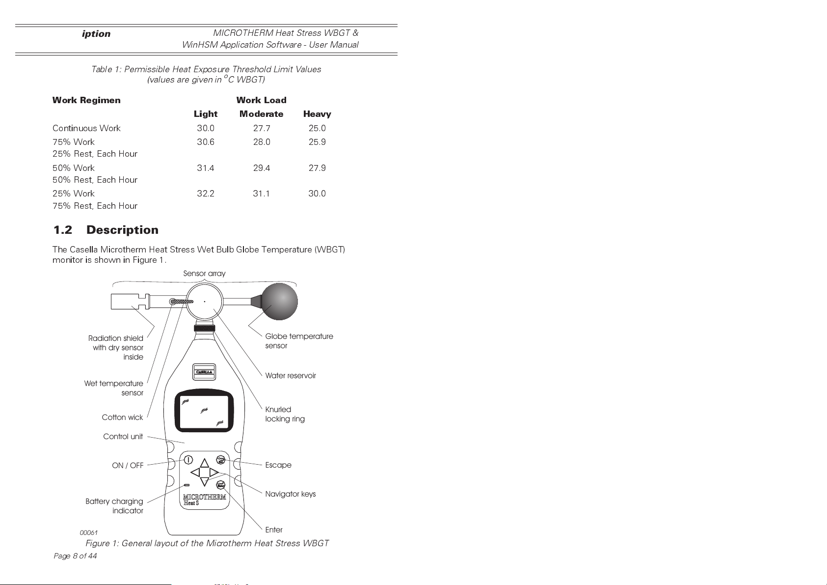
1.2 Description
The Casella Microtherm Heat Stress Wet Bulb Globe Temperature (WBGT)
monitor is shown in Figure 1.
Sensor array
Radiation shield
with dry sensor
inside
Globe temperature
sensor
Wet temperature
Battery charging
00061
Figure 1: General layout of the Microtherm Heat Stress WBGT
Page 8 of 44
sensor
Cotton wick
Control unit
ON / OFF
indicator
MICROTHERM
Heat Stress WBGT
Water reservoir
Knurled
locking ring
Escape
Navigator keys
Enter
0006
MICROTHERM Heat Stress WBGT &
WinHSM Application Software - User Manual
It is a compact, site monitoring instrument intended primarily for tripod
mounting but may also be handheld; it has the following main features.
¤
LCD graphics display
¤
Real-time display
¤
Full datalogging facilities as standard
¤
Low water level warning
¤
Built-in alarm for WBGT levels
¤
RH% and dewpoint calculation
¤
Automatic calculation of work / rest regimes via PC Software
¤
Optional tripod mounting and extension cable
¤
Meets the requirements of ISO 7234/ DIN
¤
Ergonomic design
The sensor array can be mounted directly on the instrument case, or
detached and mounted on a tripod with an extension cable to provide remote
sensing. Accuracy is achieved by using Platinum Resistance Temperature
Detectors manufactured to high standards of accuracy, stability, and
sensitivity. These sensors conform to the requirements of IEC 751 class A
and EN 60751 class A. On the sensor array, a radiation shield is provided for
the dry temperature sensor.
The instrument will operate from rechargeable batteries, primary cells, or
mains power supply while the high definition liquid crystal display is capable
of showing both text and graphical information. It also shows instrument
configuration details, temperature levels, logger information and battery
condition.
Description
The instrument uses a membrane keypad for all control functions, while a
serial (RS 232) socket is provided for data transfer to a PC for data
manipulation and presentation using Casella WinHSM application software.
Calibration modules can be provided to check the instrument's zero and span
setting.
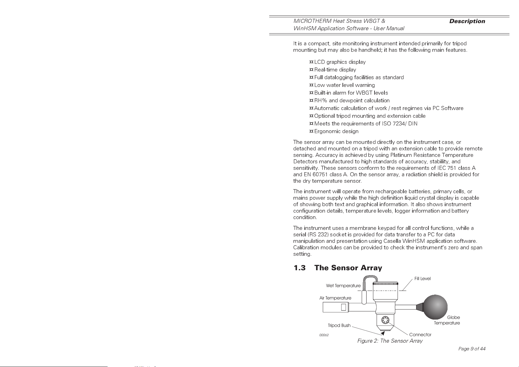
1.3 The Sensor Array
Fill Level
Wet Temperature
Air Temperature
Globe
Tripod Bush
2
Connector
Figure 2: The Sensor Array
Temperature
Page 9 of 44
Description
MICROTHERM Heat Stress WBGT &
WinHSM Application Software - User Manual
The sensor array is illustrated in Figure 2. It consists of three platinum
resistance temperature detectors (PRTD) to measure three ambient
temperatures as follows.
Wet Temperature Sensor
Mounted vertically with a tubular cotton wick over its length and the end of
the cotton extending into a water reservoir. (Always use distilled water.)
Dry Temperature Sensor
Oriented at 90
o
from the wet temperature sensor and fitted with a radiation
shield.
Globe Temperature Sensor
A sensor within a black globe monitors temperature increase due to incident
heat radiation.
The complete sensor array can be removed from the control unit and
mounted on a tripod for remote operation via extension leads up to 50 m long.
1.4 The Microtherm Menu Structure
The operator interface is based upon a series of menu options organised as
shown on the fold-out sheet at the back of this book.
A combination of function keys and navigator keys on the front panel of the
instrument are used to move around the menu system and change setup
parameters.
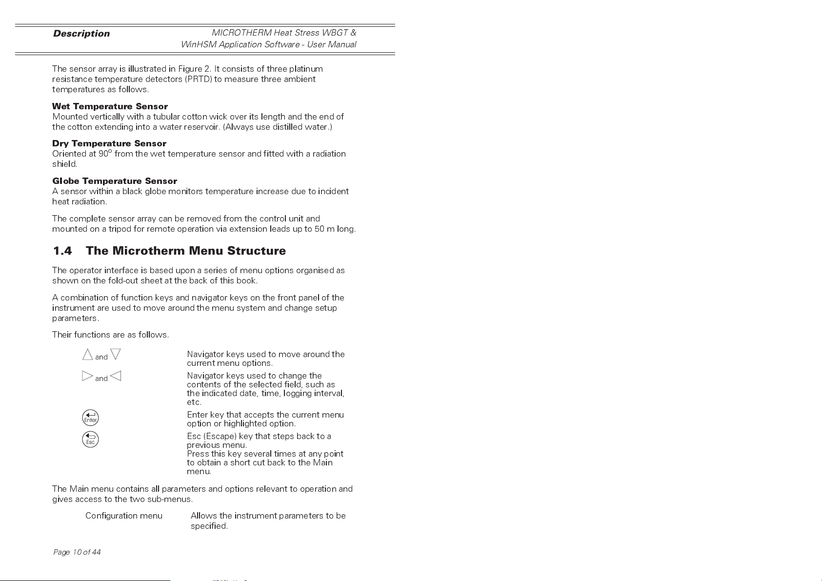
Their functions are as follows.
and
and
Enter
Esc
Navigator keys used to move around the
current menu options.
Navigator keys used to change the
contents of the selected field, such as
the indicated date, time, logging interval,
etc.
Enter key that accepts the current menu
option or highlighted option.
Esc (Escape) key that steps back to a
previous menu.
Press this key several times at any point
to obtain a short cut back to the Main
menu.
The Main menu contains all parameters and options relevant to operation and
gives access to the two sub-menus.
Configuration menu Allows the instrument parameters to be
specified.
Page10of44
4
MICROTHERM Heat Stress WBGT &
Description
WinHSM Application Software - User Manual
Logger Allows the logger to be configured and
data storage to be started and stopped.
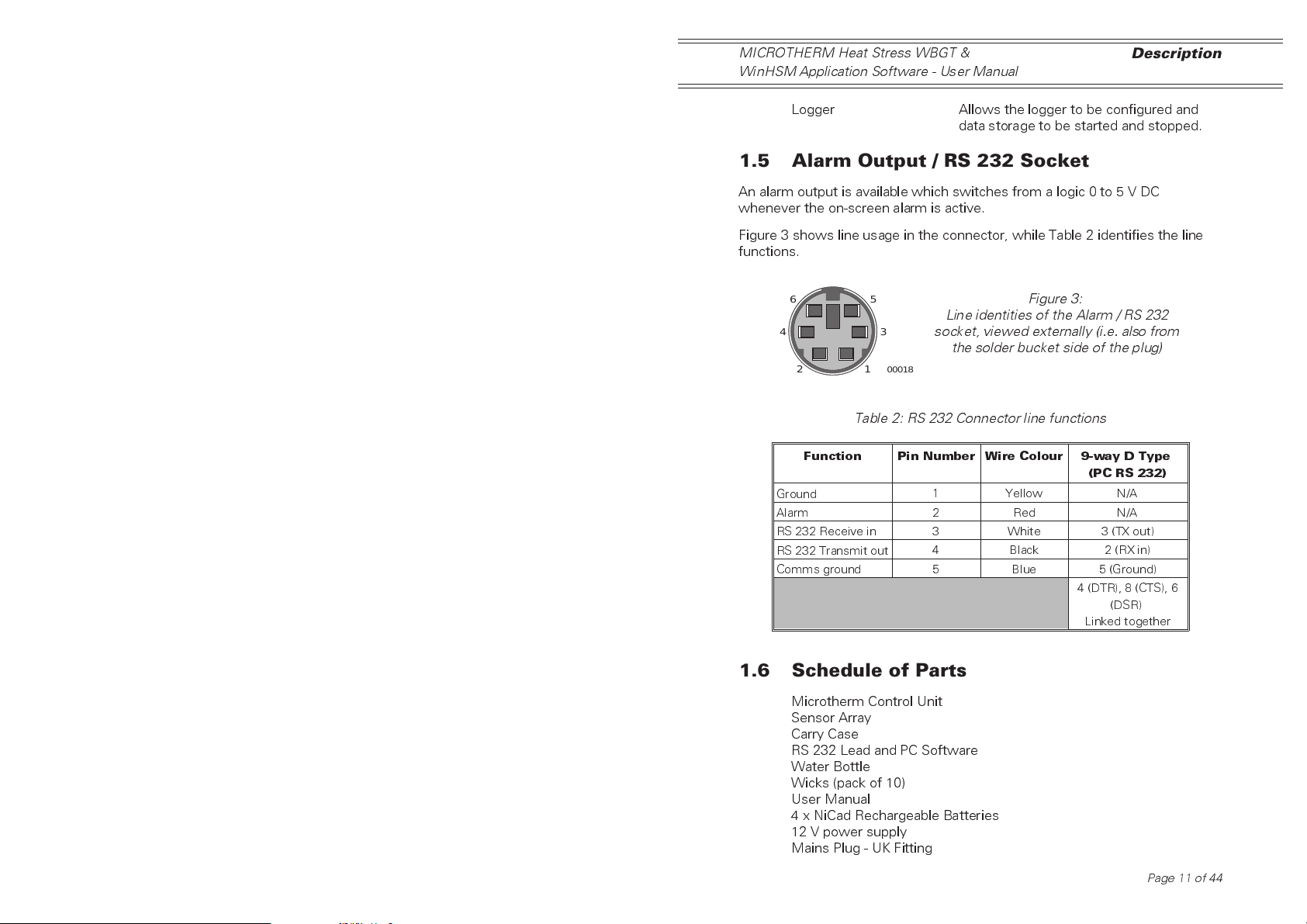
1.5 Alarm Output / RS 232 Socket
An alarm output is available which switches from a logic 0 to 5 V DC
whenever the on-screen alarm is active.
Figure 3 shows line usage in the connector, while Table 2 identifies the line
functions.
6
5
Figure 3:
Line identities of the Alarm / RS 232
3
socket, viewed externally (i.e. also from
the solder bucket side of the plug)
2
00018
1
Table 2: RS 232 Connector line functions
Function Pin Number Wire Colour 9-way D Type
(PC RS 232)
Ground
Alarm
RS 232 Receive in
RS 232 Transmit out
Comms ground
1 Yellow N/A
2 Red N/A
3 White 3 (TX out)
4 Black 2 (RX in)
5 Blue 5 (Ground)
4 (DTR), 8 (CTS), 6
(DSR)
Linked together
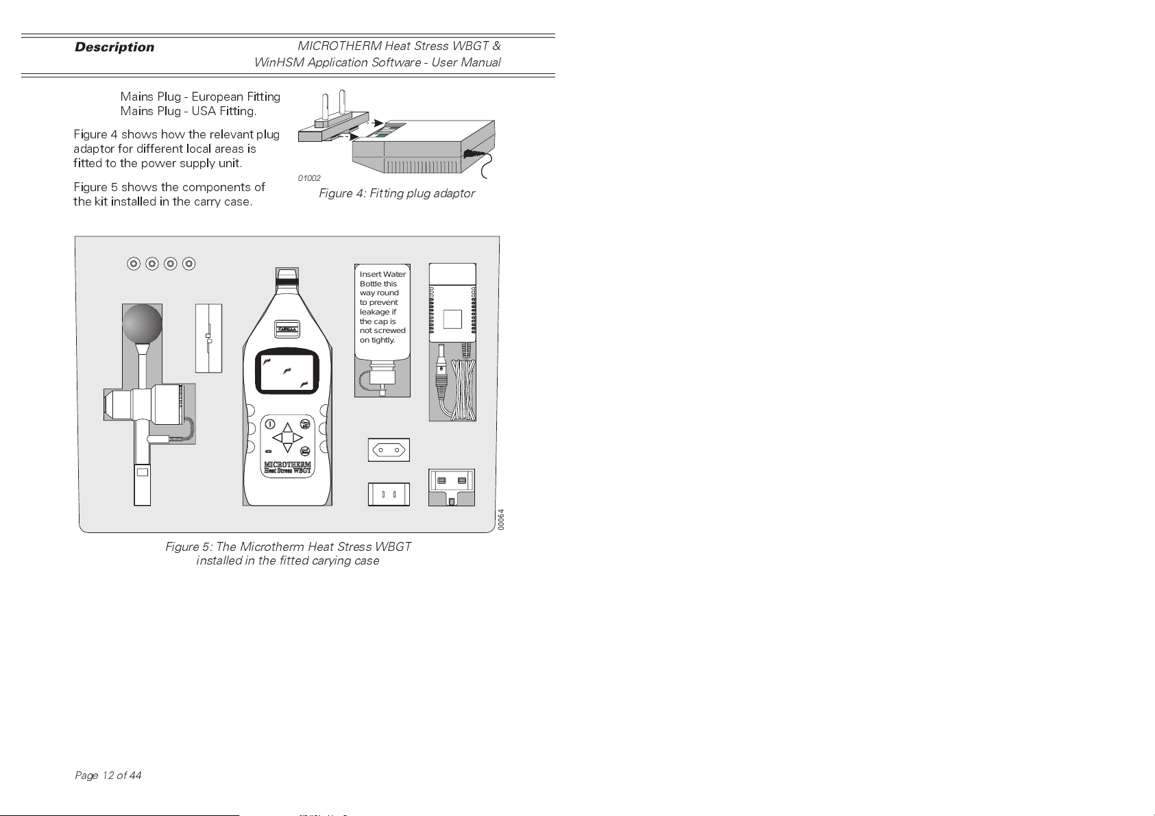
1.6 Schedule of Parts
Microtherm Control Unit
Sensor Array
Carry Case
RS 232 Lead and PC Software
Water Bottle
Wicks (pack of 10)
User Manual
4 x NiCad Rechargeable Batteries
12 V power supply
Mains Plug - UK Fitting
Page 11 of 44
0100
Description
WinHSM Application Software - User Manual
Mains Plug - European Fitting
Mains Plug - USA Fitting.
Figure 4 shows how the relevant plug
adaptor for different local areas is
fitted to the power supply unit.
Figure 5 shows the components of
the kit installed in the carry case.
MICROTHERM Heat Stress WBGT &
2
Figure 4: Fitting plug adaptor
Insert Water
Bottle this
way round
to prevent
leakage if
the cap is
not screwed
on tightly.
00064
Figure 5: The Microtherm Heat Stress WBGT
installed in the fitted carying case
Page12of44
L
R
C
MICROTHERM Heat Stress WBGT &
WinHSM Application Software - User Manual
Operation
2. OPERATION
The Microtherm Heat Stress WBGT is a sensitive scientific instrument which
should not be exposed to excessive moisture, vibration, or physical shocks.
The following steps must be performed before your Microtherm can be used
under operating conditions. It is suggested that you follow the sequence of
sections in this chapter.
2.1 Preparation for Use
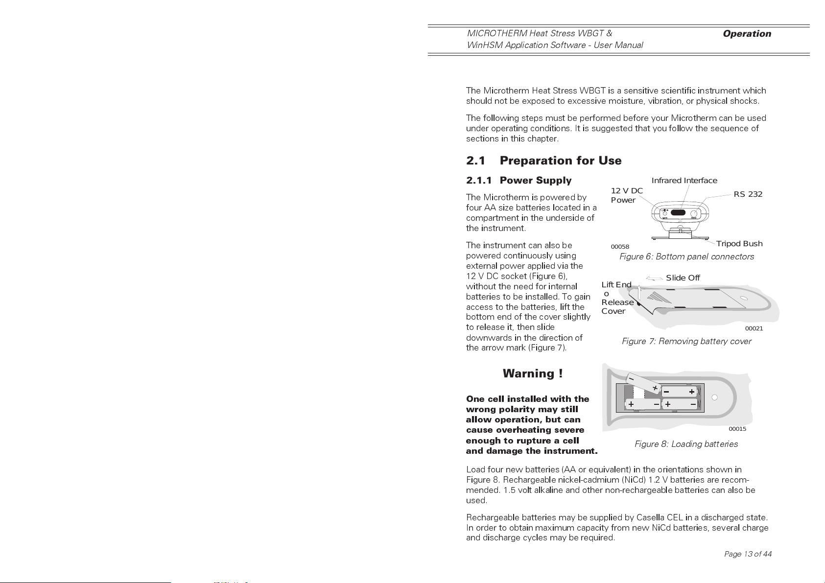
2.1.1 Power Supply
The Microtherm is powered by
four AA size batteries located in a
compartment in the underside of
the instrument.
The instrument can also be
powered continuously using
external power applied via the
12 V DC socket (Figure 6),
without the need for internal
batteries to be installed. To gain
access to the batteries, lift the
bottom end of the cover slightly
to release it, then slide
downwards in the direction of
the arrow mark (Figure 7).
Warning !
One cell installed with the
wrong polarity may still
allow operation, but can
cause overheating severe
enough to rupture a cell
and damage the instrument.
Infrared Interface
12 V DC
Power
00058
Figure 6: Bottom panel connectors
ift End
o
elease
over
Figure 7: Removing battery cover
Figure 8: Loading batteries
Slide Off
RS 232
Tripod Bush
00021
00015
Load four new batteries (AA or equivalent) in the orientations shown in
Figure 8. Rechargeable nickel-cadmium (NiCd) 1.2 V batteries are recom-
mended. 1.5 volt alkaline and other non-rechargeable batteries can also be
used.
Rechargeable batteries may be supplied by Casella CEL in a discharged state.
In order to obtain maximum capacity from new NiCd batteries, several charge
and discharge cycles may be required.
Page 13 of 44
Operation
MICROTHERM Heat Stress WBGT &
WinHSM Application Software - User Manual
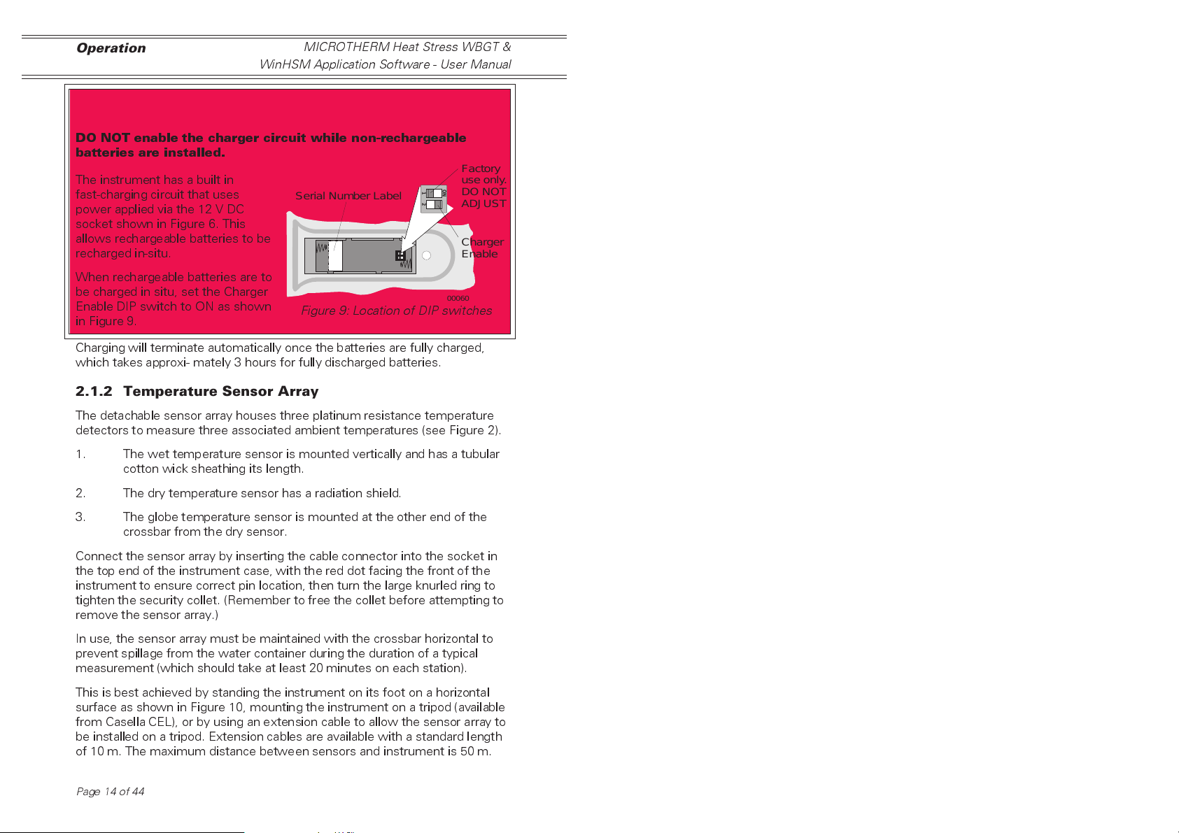
Warning !
DO NOT enable the charger circuit while non-rechargeable
batteries are installed.
Factory
The instrument has a built in
fast-charging circuit that uses
Serial Number Label
power applied via the 12 V DC
socket shown in Figure 6. This
allows rechargeable batteries to be
recharged in-situ.
When rechargeable batteries are to
be charged in situ, set the Charger
Enable DIP switch to ON as shown
in Figure 9.
Figure 9: Location of DIP switches
Charging will terminate automatically once the batteries are fully charged,
which takes approxi- mately 3 hours for fully discharged batteries.
2.1.2 Temperature Sensor Array
The detachable sensor array houses three platinum resistance temperature
detectors to measure three associated ambient temperatures (see Figure 2).
use only.
ON
1
DO NOT
2
ADJUST
Charger
Enable
00060
1. The wet temperature sensor is mounted vertically and has a tubular
cotton wick sheathing its length.
2. The dry temperature sensor has a radiation shield.
3. The globe temperature sensor is mounted at the other end of the
crossbar from the dry sensor.
Connect the sensor array by inserting the cable connector into the socket in
the top end of the instrument case, with the red dot facing the front of the
instrument to ensure correct pin location, then turn the large knurled ring to
tighten the security collet. (Remember to free the collet before attempting to
remove the sensor array.)
In use, the sensor array must be maintained with the crossbar horizontal to
prevent spillage from the water container during the duration of a typical
measurement (which should take at least 20 minutes on each station).
This is best achieved by standing the instrument on its foot on a horizontal
surface as shown in Figure 10, mounting the instrument on a tripod (available
from Casella CEL), or by using an extension cable to allow the sensor array to
be installed on a tripod. Extension cables are available with a standard length
of 10 m. The maximum distance between sensors and instrument is 50 m.
Page14of44
 Loading...